High Ambient Light Electronic Screen Communication Method
ACKLEY; H. Sprague ; et al.
U.S. patent application number 16/254057 was filed with the patent office on 2019-05-23 for high ambient light electronic screen communication method. The applicant listed for this patent is Hand Held Products, Inc.. Invention is credited to H. Sprague ACKLEY, Damien Francou.
| Application Number | 20190156169 16/254057 |
| Document ID | / |
| Family ID | 63854574 |
| Filed Date | 2019-05-23 |


| United States Patent Application | 20190156169 |
| Kind Code | A1 |
| ACKLEY; H. Sprague ; et al. | May 23, 2019 |
HIGH AMBIENT LIGHT ELECTRONIC SCREEN COMMUNICATION METHOD
Abstract
The present invention embraces a method to obtain barcoded information off a computer screen under high ambient lighting conditions, including a direct sunlight environment. The method includes a user prompting a computer to present an active window on all or a portion of its screen. The computer generates a communication sequence, comprising information commonly included on a barcode, and displays the communication sequence on the computer screen. After activating the scanner into an alternative or screen mode, the user places the scanner on the active window of the computer screen and the scanner asynchronously receives the communication sequence. The scanner decodes the received communication sequence and obtains encoded information of the computer. The encoded information may include a unique identifier of the computer, such as a MAC address. With the MAC address, the scanner may wirelessly communicate with the computer to exchange other information.
| Inventors: | ACKLEY; H. Sprague; (Seattle, WA) ; Francou; Damien; (Lynnwood, WA) | ||||||||||
| Applicant: |
|
||||||||||
|---|---|---|---|---|---|---|---|---|---|---|---|
| Family ID: | 63854574 | ||||||||||
| Appl. No.: | 16/254057 | ||||||||||
| Filed: | January 22, 2019 |
Related U.S. Patent Documents
| Application Number | Filing Date | Patent Number | ||
|---|---|---|---|---|
| 15491383 | Apr 19, 2017 | 10223626 | ||
| 16254057 | ||||
| Current U.S. Class: | 1/1 |
| Current CPC Class: | H04W 76/14 20180201; G06K 7/10722 20130101; H04W 84/18 20130101; G06K 7/1095 20130101; G06K 19/06028 20130101; H04L 61/6022 20130101; G06K 7/1413 20130101; H04W 4/80 20180201; G06K 19/06112 20130101 |
| International Class: | G06K 19/06 20060101 G06K019/06; G06K 7/14 20060101 G06K007/14; G06K 7/10 20060101 G06K007/10; H04W 76/14 20060101 H04W076/14 |
Claims
1.-20. (canceled)
21. A method of communicating with an electronic device comprising the steps of: in response to being in a display screen reading mode and being within imaging range of a display screen, capturing, by a barcode scanner, a sequence of multi-state frames displayed on the display screen wherein the sequence of multi-state frames comprise a bit-wise information stream; activating a user perceptible indicator at the barcode scanner upon reception of a complete transmission from digital display; and entering, by the barcode scanner, a bar code reading mode.
22. The method according to claim 21, wherein, the sequence of multi-state frames comprises three optical states including an "on" state, an "off" state, and an intermediate state, wherein, the three optical states are represented by respective colors; at the "on" state or the "off" state, the sequence of multi-state frames transitions to and from the intermediate state; and at the intermediate state, the sequence of multi-state frames transitions to and from either the "on" state or the "off" state.
23. The method of claim 22, wherein the intermediate state is displayed as a light steel blue, wherein the light steel blue is represented with an html color code of #B0C4DE.
24. The method according to claim 22, wherein the "on" state, the "off" state or the intermediate state have a duration that is at least as long as a frame duration associated with a barcode scanner frame rate.
25. The method according to claim 22, wherein, a transition from the intermediate state to the "on" or off" state and back to a transition state comprises one bit of information; and a transmission period for one bit is equal to two times a frame duration plus two times a sum of a rise time plus a fall time.
26. The method according to claim 21, wherein the bit-wise information stream is bounded by a series of frames without bit-wise information.
27. The method according to claim 21, wherein the sequence of multi-state frames is displayed on a portion of the digital display.
28. The method of claim 21, wherein the bit-wise information stream comprises a media access control address of the electronic device connected to the display screen.
29. The method of claim 28, further comprising: establishing, by the barcode scanner, a communication link to the electronic device associated with the media access control address.
30. The method of claim 21, further comprising: detecting, by the barcode scanner, a magnitude of a frame by averaging a group of pixels of the display screen for each frame of the sequence of multi-state frames.
31. A method of transmitting a machine-readable code information with a digital display communicatively coupled to an electronic device comprising the steps of: converting the machine-readable code information into a sequence of multi-state frames, wherein the sequence of multi-state frames comprise a bit wise information stream; and displaying by the digital display the sequence of multi-state frames.
32. The method according to claim 31, wherein, the sequence of multi-state frames comprises a group of optical states including an "on" state, an "off" state, and an intermediate state, wherein, each optical state represents a different color; on an active window of the digital display, the "on" state is displayed as a white color, the "off" state is displayed as a black color, and the intermediate state is displayed as a gray color; at the "on" state or the "off" state, the sequence of multi-state frames transitions to and from the intermediate state; and at the intermediate state, the sequence of multi-state frames transitions to and from either the "on" state or the "off" state.
33. The method according to claim 32, wherein, the "on" state, the "off" state or the intermediate state have a duration that is at least as long as a frame duration associated with a barcode scanner frame rate.
34. The method according to claim 32, wherein, a transition from the intermediate state to the "on" or off" state and back to a transition state comprises one bit of information; and a transmission period for one bit is equal to two times a frame duration plus two times a sum of a rise time plus a fall time.
35. The method according to claim 32, wherein the intermediate state is displayed as a light steel blue, wherein the light steel blue is represented with an html color code of #B0C4DE.
36. The method according to claim 31, further comprising detecting a magnitude of the sequence of multi-state frames by averaging pixels of the digital display.
37. The method according to claim 31, wherein the electronic device is a computer.
38. The method according to claim 37, wherein the machine-readable code information comprises a media access control address of the computer.
39. The method according to claim 31, wherein the sequence of multi-state frames comprise a bit-wise information stream and wherein the bit-wise information stream is bounded by a series of frames without bit-wise information.
Description
FIELD OF THE INVENTION
[0001] The present invention relates to methods of communicating with a computer, and in particularly methods of transferring information via screen communication to a bar code scanner in a high ambient light environment without the limitation of an in-focus optics system.
BACKGROUND
[0002] Generally speaking, the proliferation of 2D Imagers and their ease of operation have increased the demand for reading barcode symbols off a computer screen. Reading on-screen barcodes allows customers to take advantage of their inherent ability to be dynamically-created and therefore accommodate variable data, such as PC-specific Bluetooth MAC addresses. These techniques may support mission-critical applications such as package delivery. However, this process may break down in high ambient light environments. Often, the computer screen is located where significant and uncontrollable amounts of ambient light are flooding the screen, making the on-screen barcodes unusable.
[0003] Therefore, a need exists for a method to obtain the barcoded information off a computer screen under high ambient lighting conditions.
SUMMARY
[0004] Accordingly, in one aspect, the present invention embraces a method to transmit data between a computer screen and a decoding device utilizing an asynchronous communication method and an out-of focus condition for the decoding device. The data may be information which may have been encoded in a barcode and the decoding device may be a barcode scanner. The method may operate in a high ambient lighting environment, such as direct sunlight.
[0005] In an exemplary embodiment, the method of communicating with a computer may comprise activating a scanner to operate in a screen mode (or an alternative mode); and placing the scanner in contact with an active window displayed on a screen of the computer. The computer receives a prompt to cause the active window to be displayed on the screen, and the computer displays a communication sequence on the active window. The method continues with the scanner scanning the active window to asynchronously receive the communication sequence that comprises encoded information. The scanner operates in a defocused focus condition of the scanner and can operate successfully in a direct sunlight environment. The method further continues with the scanner converting the received encoded information to a unique identifier of the computer; and connecting the scanner to the computer using the unique identifier via an electronic communication method. The communication sequence comprises at least three optical states.
[0006] The active window is displayed on a portion of the screen of the computer. The unique identifier of the computer may be, but is not limited to, a MAC address. The electronic communication method may utilize, but is not limited to, a Bluetooth Low Energy (LE) technology.
[0007] In another exemplary embodiment, a method of communicating with a computer with a screen may comprise scanning, with a scanner, to detect a magnitude of an output of the screen, converting, by the scanner, the output of the screen into encoded information; and coupling the scanner to the computer using the encoded information. The computer causes all or part of the screen to display the output. The encoded information varies at least at a frame rate of the screen. The scanner operates independent of any focus condition. The output of the screen may be a multi-state sequence.
[0008] The scanner detects the magnitude of the output by averaging the pixels of the screen. The scanner may average all of the pixels of the screen. The scanner may use its internal CMOS sensor for this detection. The changing screen states enable asynchronous communications. The encoded information may comprise one or more instructions intended for the scanner. For example, the encoded information may include a MAC address. The scanner operates in a direct sunlight environment. The communication sequence may comprise a sequence of more than three optical states.
[0009] In yet another exemplary embodiment, a method of communicating with a computer may comprise receiving a prompt, at the computer, to cause a window to be displayed on a screen of the computer; displaying, by the computer, on the window a communication sequence comprising encoded information, wherein a scanner performs the steps of: (i) activating the scanner to operate in a screen mode) (or an alternative mode), (ii) placing the scanner in contact with the window, (iii) scanning the window with the scanner to asynchronously receive encoded information, and (iv) converting the received encoded information from the computer to a unique identifier of the computer. The method continues with the computer connecting the scanner to the computer using the unique identifier via an electronic communication method. The scanner operates independent of any focus condition of the scanner and operates independent of a direct sunlight environment. The communication sequence comprises a sequence of three optical states.
[0010] The aforementioned exemplary embodiments may include the following elements: The communication sequence may comprise a sequence of three optical states including an "on" state, an "off" state, and an intermediate state. On the active window, the "on" state is displayed as a white color, the "off" state is displayed as a black color, and the intermediate state is displayed as a gray color. At the "on" state or the "off" state, the communication sequence or multi-state sequence transitions to and from the intermediate state. At the intermediate state, the communication sequence or multi-state sequence transitions to and from either the "on" state or the "off" state. The "on" state, the "off" state or the intermediate state have at least a duration of a scanner frame rate. A transition from the intermediate state to the "on" or "off" state and back to a transition state comprises one bit of information. A transmission period for one bit is equal to two times a frame duration plus two times a sum of a rise time plus a fall time. The communication sequence or output is displayed by the computer onto the computer screen, or a portion of the computer screen.
[0011] In yet another exemplary embodiment, a method of communicating with a computer comprises activating a scanner to operate in a barcode mode. The scanner then attempts to decode a barcode displayed on a computer screen. If the scanner does not successfully decode the barcode: (i) the operation of the scanner changes to a screen mode, and (ii) the scanner proceeds to process a plurality of frames in a communication sequence displayed on the computer screen. The scanner then determines if the communication sequence comprises multiple states in the frames of the communication sequence.
[0012] If the communication sequence comprises multiple states, the scanner continues to decode the plurality of frames comprising bits of encoded information. After receiving and decoding a full bit stream, the operation of the scanner returns to the barcode mode. The scanner converts the encoded information to a unique ID of the computer, and proceeds to wirelessly connect to the computer using the unique ID.
[0013] In the barcode mode, if the scanner successfully decodes the barcode, the decoded barcode may be transmitted to a host computer. Then, the scanner repeats the operation in the barcode mode by attempting to decode another barcode. In the screen mode, if the communication sequence does not comprise multiple states, the operation of the scanner may be returned to the barcode mode.
[0014] In yet another exemplary embodiment, a method of obtaining a machine-readable code information with a barcode scanner from a digital display comprising the steps of: converting the machine-readable code information into a communication sequence comprised of sequential images, wherein each sequential image is defined by at least three colors or patterns; configuring the barcode scanner to operate in a manner that analyzes a plurality of images sequentially; displaying by the digital display the communication sequence; receiving with the barcode scanner the communication sequence, wherein the barcode scanner captures the sequential images; converting the captured sequential images back into the machine-readable code information; and connecting the barcode scanner to a computer using a unique identifier via an electronic communication method.
[0015] The communication sequence comprises a sequence of three optical states including an "on" state, an "off" state, and an intermediate state. Each optical state represents a different color. On the active window, the "on" state is displayed as a white color, the "off" state is displayed as a black color, and the intermediate state is displayed as a gray color. At the "on" state or the "off" state, the communication sequence transitions to and from the intermediate state; and at the intermediate state, the communication sequence transitions to and from either the "on" state or the "off" state. The "on" state, the "off" state or the intermediate state have at least a duration of a barcode scanner frame rate.
[0016] In yet another exemplary embodiment, a system for obtaining a machine-readable code information with a barcode scanner from a digital display, the system comprising: a computer capable of generating a multi-state sequence based on the machine-readable code information and presenting the multi-state sequence on the digital display; the barcode scanner capable of scanning the digital display and receiving the multi-state sequence using out-of-focus asynchronous data transmission, wherein, the barcode scanner converts the multi-state sequence back into the machine-readable code information; and the digital display for displaying the multi-state sequence.
[0017] The foregoing illustrative summary, as well as other exemplary objectives and/or advantages of the invention, and the manner in which the same are accomplished, are further explained within the following detailed description and its accompanying drawings.
BRIEF DESCRIPTION OF THE DRAWINGS
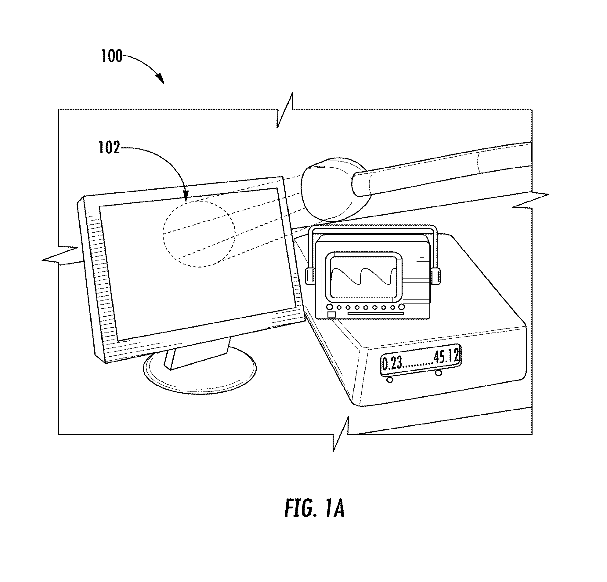
[0018] FIG. 1A illustrates a computer screen flooded with ambient light.
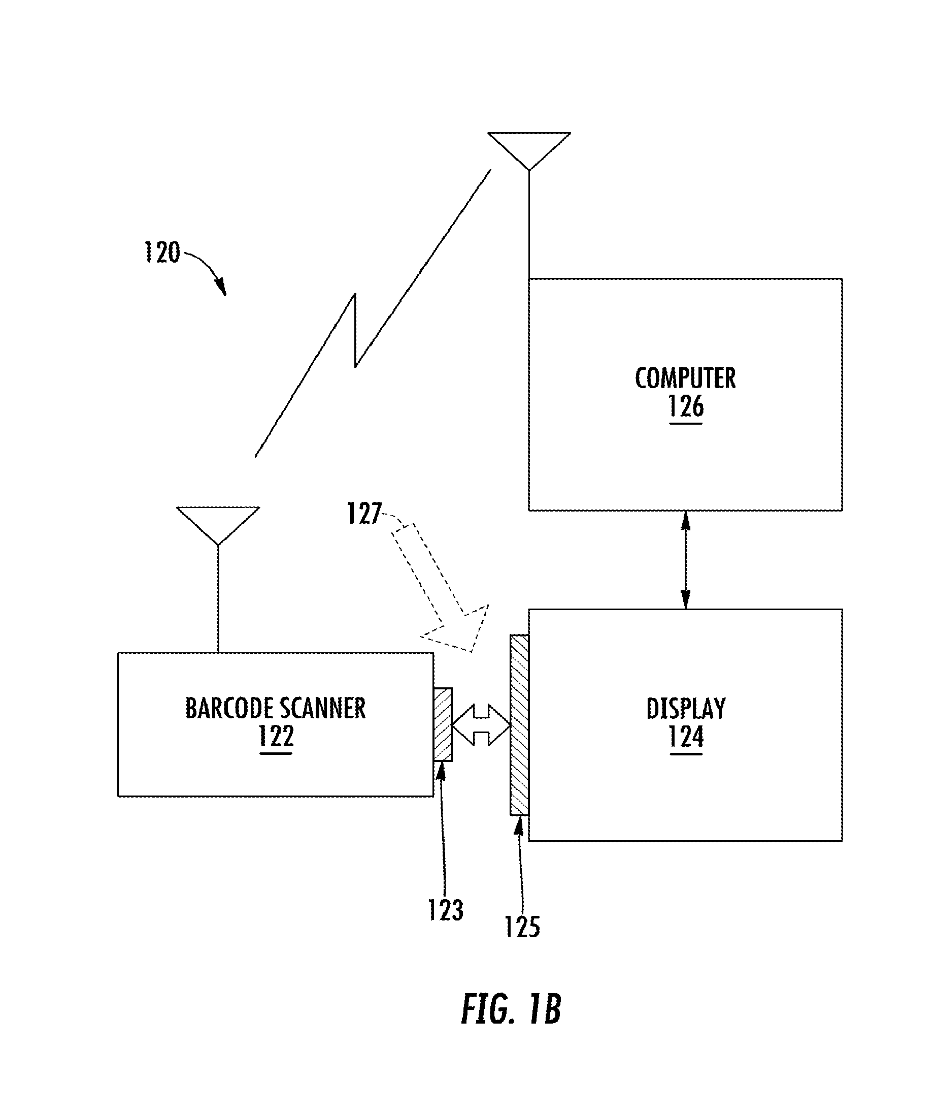
[0019] FIG. 1B illustrates a system for obtaining barcoded information off a computer screen under high ambient lighting conditions.
[0020] FIG. 2 illustrates an exemplary embodiment of a communication sequence that is displayed on the computer screen and subsequently scanned by a scanner in a high ambient light environment such as illustrated in FIG. 1A and FIG. 1B.
[0021] FIG. 3 illustrates another exemplary embodiment of the communication sequence that is produced by the scanner, after the communication sequence has been displayed on the computer screen.
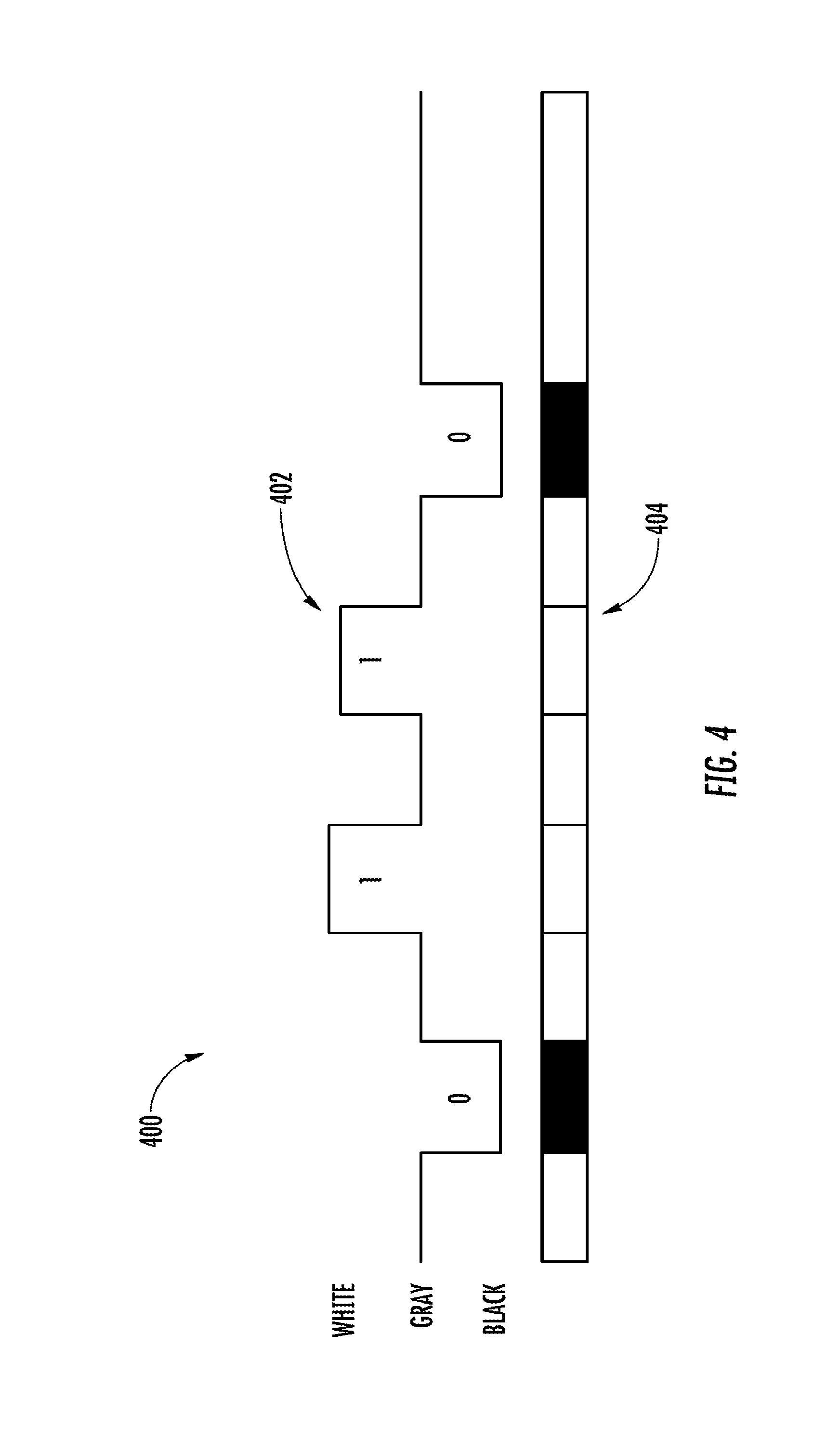
[0022] FIG. 4 illustrates yet another exemplary embodiment of the communication sequence that is displayed on the computer screen including the white-gray-black pattern displayed on the computer screen.
[0023] FIG. 5 is a flow diagram illustrating a method of receiving at a scanner the communication sequence that includes encoded information.
[0024] FIG. 6 is a flow diagram illustrating another method of receiving at a scanner the communication sequence that includes encoded information.
DETAILED DESCRIPTION
[0025] The present invention embraces a method to obtain barcoded information off a computer screen under high ambient lighting conditions, including a direct sunlight environment. The method includes a user prompting a computer to present an active window on all or a portion of its screen. The computer generates a communication sequence, comprising information normally included in a barcode, and displays the communication sequence on the computer screen. After activating the scanner into a screen mode (or an alternative mode), the user places the scanner on the active window of the computer screen and the scanner asynchronously receives the communication sequence. The scanner decodes the received communication sequence and obtains encoded information from the computer. The encoded information may include a unique identifier of the computer, such as a MAC address. With the MAC address, the scanner may wirelessly communicate with the computer to exchange other information. The other information may include tracking the location of product inventory in a facility.
[0026] The present invention may be useful in an industrial environment where a user is picking up a product from inventory and delivering it to a delivery location in the facility. To track the user's activity, the user first connects to a specific computer. The connection includes reading three bar codes. The first barcode resets the scanner; the second barcode reconfigures the scanner or operation; and the third barcode includes a unique identifier of the computer. The unique identifier may be a MAC address.
[0027] After connecting with the specific computer, the user may walk in the facility and pick up a product and deliver it to a delivery location in the facility. At each stop, the user reads the barcode of the product, which is immediately transmitted to the specific computer. Accordingly, the location of the product is tracked by the specific computer. The specific computer is often in a high ambient light environment. A work around for this situation may include posting the barcodes on a piece of paper and attaching the paper to the specific computer. The scanner may be able to read the barcode on the paper in a high ambient light environment, but the paper may become lost or damaged. The present invention provides a method to avoid such a work around.
[0028] As described, herein, a communication sequence is equivalent to a communication signal. An optical state is equivalent to a color. A scanner is equivalent to a barcode scanner. A communication sequence may be a multi-state sequence.
[0029] FIG. 1A illustrates an embodiment 100 of a computer screen flooded with ambient light 102. The high ambient light environment may inhibit a barcode scanner from reading a barcode on the computer screen. The present invention may solve this problem by creating a small "window" on the computer screen that changes light intensity uniformly, allowing the scanner to be in contact with the screen and to operate in any focus condition including out-of-focus.
[0030] FIG. 1B illustrates a system 120 for obtaining barcoded information off a computer screen under high ambient lighting conditions, as depicted in FIG. 1A. System 120 comprises barcode scanner 122 that includes a scanner optical input/output (I/O) port 123, display 124 that includes a visual portion of the display 125, computer 126, and high ambient light 127. As illustrated, barcode scanner 122 attempts to reads a barcode off display 124 via the scanner optical I/O port 123 and visual portion of the display 125. Inasmuch as a successful reading of a barcode may not be possible, the user of barcode scanner 122 changes from a barcode reading mode to a screen scanning mode (or screen mode) and requests the computer 126 to display a communication sequence representing the barcode information. As illustrated, barcode scanner 122 can wirelessly communication with computer 126. Although not shown, barcode scanner 122 can communication with computer 126 on a non-wireless basis. A "screen mode" is sometimes referred to as an "alternative mode."
[0031] The present invention may also solve the problem of how to communicate information without using a method to synchronize to the computer screen. Other methods have relied on using the time-dependent rastering scans for each frame of a CRT display to transmit a byte and a focused photodiode to receive the information in a synchronized fashion. This CRT method may not be useful with current screen technology and may be very sensitive to high ambient light conditions. Also, the CRT method may use the entire frame to transmit a bit and the receiving device may need to be focused. In the present invention, the method of communicating information may not need to be synchronized and may not need to rely on time dependent frame generation. Moreover, the receiving device may be a standard imaging barcode scanner.
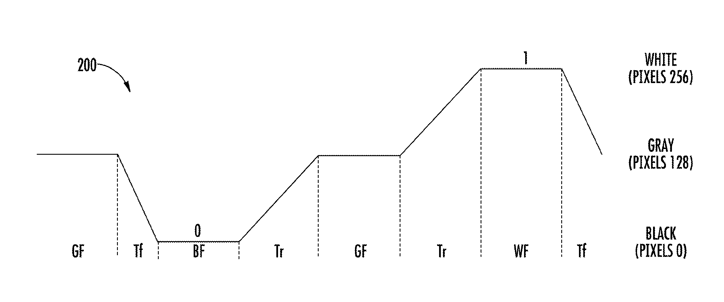
[0032] FIG. 2 illustrates an exemplary embodiment of a communication sequence 200 that is displayed, i.e., projected, on the computer screen and subsequently scanned by a scanner in a high ambient light environment such as illustrated in FIG. 1. The display or projection of communication sequence 200 may be on all or a designated area of the computer screen such as in the lower right corner of the computer screen.
[0033] The scanner, such as a Honeywell SF61, may run at 60 frames per second, meaning the scanner may capture a new image approximately every 17 ms (i.e., the frame duration, or Ts is 17 ms). This situation may limit the fundamental information transfer since a "bit" has to be captured during this time period. A "bit" may be defined when the screen is either all on or all off. An LCD screen, Honeywell CV61, may have a "rise" time of 36 ms and a "fall" time of 20 ms between the two optical states that comprise a bit. The problem becomes how to make sure that the scanner sees the "on" state without missing it, while at the same time being sure that the scanner does not capture the bit twice. One solution is to utilize an intermediate state where half the screen illumination is on and half off creating a gray level that may serve as a "catch up" zone both to be sure that at least one frame is caught and to know when two frames are caught so as to avoid a double count.
[0034] The definition of a bit is therefore a process where the screen transitions from gray to, all-white (i.e., "on") and stays "on" for approximately 17 ms, then transitions back to gray for approximately 17 ms. This method may allow for two "on states" of the same value to be adjacent, since they are separated by a gray period. This method may allow for two "on states" to be adjacent, but not separated by a gray value, thereby allowing the scanner to ignore one of the "on states". This method may also allow for the accounting of any intermediate point of the rise and fall of the screen.
[0035] FIG. 2 shows the method of the present invention diagrammatically, and specifically the encodation of two bits, 01, on the CV61 display screen as a function of time. The encodation starts on the left with a gray frame that may be long enough to be sure the scanner does not miss a frame. The frame duration may be 17 ms because in the worst case, the scanner captures a frame every 17 ms. Hence, the method may not miss the gray frame. The 10 ms is half the "fall" time (Tf) to the first "off state" that needs to stay at zero level (off=0) again for 17 ms. The 18 ms is half the screen's inherent "rise" time (Tr) to return to gray that allows the scanner to become ready to measure the next "on or off" state, which in this example may be 256 (on=1). An "on" state (white) means that all pixels (256) are turned on. An "off" state (black) means that no pixels (zero) are turned on. A gray level means that half the pixels (128) are turned on or all the pixels are set at an intermediate color, such as light blue.
[0036] FIG. 2 also shows the minimum times for display output on the CV61 display screen to generate two bits dependably. The "on" or white state must be of at least the duration of the scanner frame rate to be sure to capture it. There may be an intermediate state, gray, to distinguish between two adjacent "on" or "off" states. The 1/2 rise time (Tr) and 1/2 fall time (Tf) are inherent in the display and are 18 and 10 ms respectively in this exemplary embodiment.
[0037] The intermediate state (where half the screen illumination is on and half off) creates a gray level that serves as a neutral or "rest" condition, and provides a mechanism for bit synchronization.
[0038] The total time for transmission of a bit is 2(Ts)+2(Tr+Tf). For 2 bits=4(17 ms)+2 (10 ms+18 ms)=124 ms. For 40 bits=124.times.20=2.5 s. For 48 bits=124.times.24=3.0 s ("s"=second, "ms"=milli-second). Ts is the frame duration.
[0039] When the scanner receives the MAC address of the computer, the scanner may wirelessly communicate with the computer. As it turns out, there may be some repeating data in the MAC address for the CV61 that may be the same 6-digit prefix and may be 001040, which may basically identify the chipset vendor. For example, valid CV61 MAC addresses may be: 00104057a64c, 001040b6afe3, and 00104042d4a0. Consequently, six hex characters must be represented, which is three bytes or 24 bits, in order to be useful to the application. Check bits could be added as well as a gray prefix and still be within the practical range of about two seconds of contact time with the display screen.
[0040] In summary, FIG. 2 illustrates a communication sequence comprising a sequence of three optical states. The communication sequence includes 2 bits, a "01" bit pattern. The time to transmit 2 bits=(2GF+BF+WF)+2(Tr)+2(Tf), where GF=gray frame; BF=black frame; WF=white frame; Tr=1/2 rise time; Tf=1/2 fall time. For one embodiment: GF=BF=WF=17 ms; Tf=10 ms; Tr=18 ms. A rise time equals the rise from the black level to the white level; similarly for the fall time. Tr may be a different value than Tf. The number of pixels displayed is the bit state. In another exemplary embodiment, the communication sequence may comprise a sequence of more than three optical states.
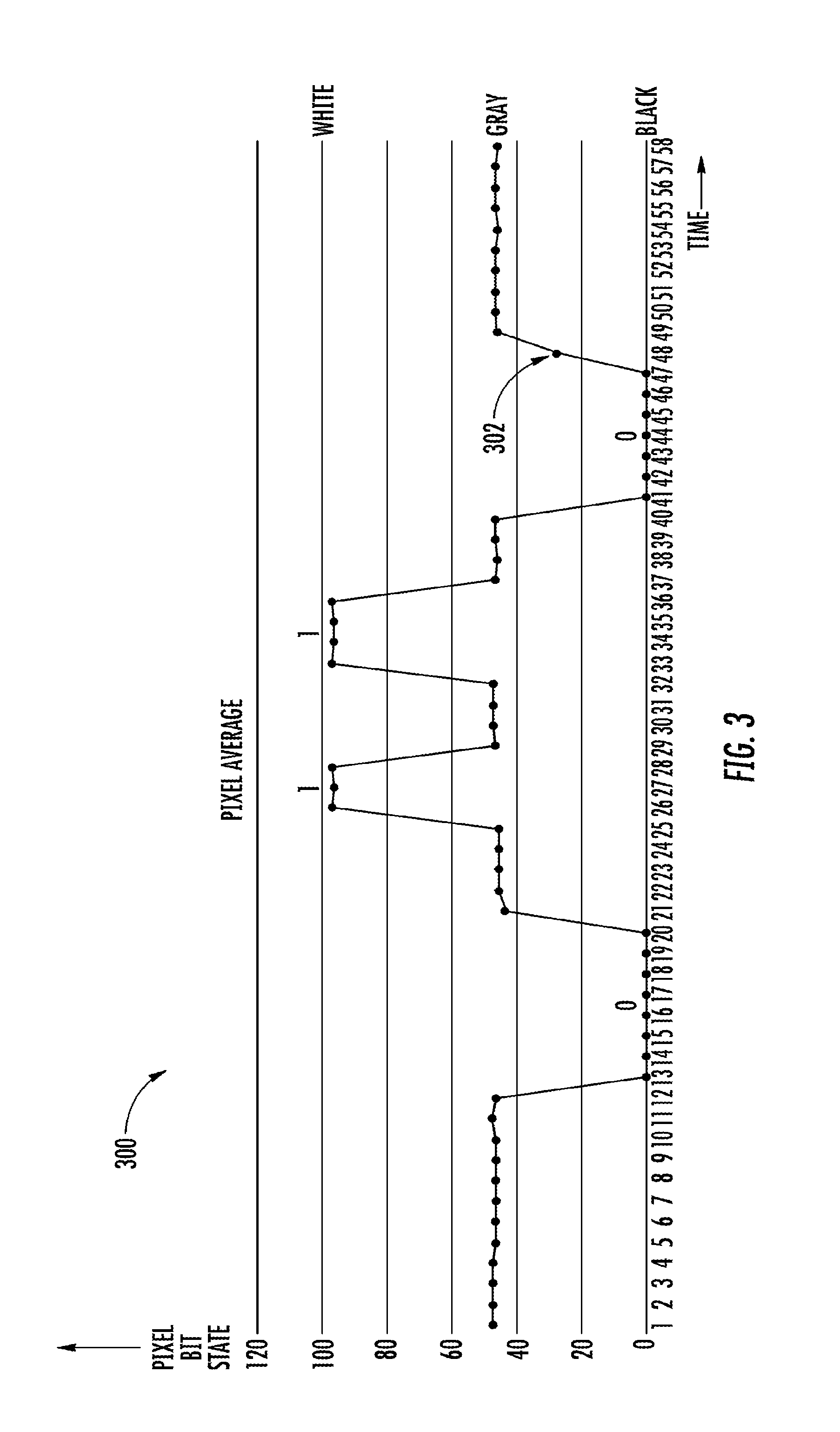
[0041] FIG. 3 illustrates another exemplary embodiment of the communication sequence that is produced by the scanner, after the communication sequence has been displayed on the computer screen. The communication sequence 300 of the present invention may be simulated by turning the screen on, off, or to gray. The scanner can detect the value of the constant state with the following algorithm:
TABLE-US-00001 int MatrixPluginDecode(unsigned char *pBuffer, int width, int height){ int iRow, iCol; unsigned long ulSum, ulAvrg; int MaxRow = 640; //# of vertical pixels int MaxCol = 844; //# of horizontal pixels ulAvrg = 0; for (iRow = 0; iRow < MaxRow; iRow++){ ulSum = 0; for (iCol = 0; iCol < MaxCol; iCol++){ ulSum += pBuffer[iCol + iRow * MaxRow]; } ulSum /= MaxCol; ulAvrg += ulSum; } ulAvrg /= MaxRow; printf("%u\r\n", ulAvrg); //outputs pixel average value to host computer }
[0042] In this code, snippet "ulAvrg" is the variable of interest; it may represent the pixel average values returned by an Xenon scanner of its entire sensor area, for a single acquisition. The resulting output of the scanner (i.e. all successive acquisitions) at the end of the experiment is then fed into a spreadsheet and displayed graphically, as shown FIG. 3. The pixel average values are shown on the Y-axis, and taken together in sequence, illustrate a "0110" bit pattern. The pixel average values are represented by a bit state measured on a scale from 0 to 255, where 0 represents "perfect black" and 255 represents "perfect white". This measurement is essentially the average value for all pixels of the sensor, where each individual pixel is encoded as an 8-bit value. In the aforementioned experiment, a "perfect white" was not achieved. Rather, a white frame was measured at approximately 100 bits state.
[0043] FIG. 4 illustrates yet another exemplary embodiment 400 of communication sequence 402 that is displayed on the computer screen including the white-gray-black pattern displayed on the computer screen. The present invention may be demonstrated utilizing the following devices: a standard Android tablet (e.g., Galaxy Tab 2 by Samsung) and a standard Xenon 1900 barcode scanner by Honeywell, with a black & white CMOS sensor. An Android application named AndroidScreenFlicker was created for the purpose of this experiment. The result of the experiment is illustrated in exemplary embodiment 400 of FIG. 4. The time-distributed pattern of communication sequence 402 is displayed, i.e. projected, on the LCD screen and alternates on the LCD screen of the tablet between the 3 defined color states i.e., the white-gray-black pattern 404. If each frame is approximately 17 ms, the user may not be able to observe the change in the white-gray-black pattern 404, and the LCD screen may appear gray during the projection of the communication sequence 402. The projection results in communication sequence 402 comprising the bits 0110 which may be the same as the bit pattern of FIG. 3. In this experiment, each time slot has a fixed 1-second duration, although other time periods may be selected for the experiment. The aforementioned Android application may be implemented on another OS, i.e., the application is OS agnostic.
[0044] In the experiment, special attention was taken to ensure that gray levels are effectively converted into a median value, and in this particular experiment the best performing color was Light Steel Blue. An example color may be html color code #B0C4DE, as defined at W3schools.com.
[0045] This experiment also highlights the importance of having an intermediate state (where all the pixels are Light Steel Blue or other intermediate color or half the screen illumination is on and half off creating a gray level to the scanner) since the scanner may capture an image at any given time including during the "rise" and the "fall" time of the LCD screen, as illustrated by indicator 302 in FIG. 3. The intermediate state creates a gray level that serves as a neutral or "rest" condition, and provides a mechanism for bit synchronization.
[0046] FIG. 5 is a flow diagram 500 illustrating a method of receiving at a scanner a communication sequence that includes encoded information. The method may comprises the steps of:
[0047] User prompts a computer to display an active window on the computer screen. (step 502) The prompting may include the user touching the "touch screen" of the computer. An active window on the computer screen changes light intensity uniformly to allow the scanner to be in contact with the screen and to operate in any focus condition, including out-of focus
[0048] User activates the scanner in a screen mode. (step 504)
[0049] User physically places the opening of the scanner in contact with the active window of the computer screen (step 506
[0050] Scanner begins to receive bits of encoded information. (step 508) Reception of bits may begin essentially immediately after the scanner in placed in contact with the active window. The bits may be received via asynchronous communication.
[0051] After receiving a full bit stream, the scanner converts the encoded information to a unique identifier of the computer. The unique identifier may be a MAC address of the computer (step 510). After a successful reception and conversion of the bit stream, the scanner provides a positive notification to the user, such as turning on a light, generating a sound or causing a vibration.
[0052] Scanner connects with computer utilizing ad hoc communication and the MAC address. (step 512)
[0053] Scanners may have several embodiments of operation. In one embodiment, the scanner continuously scans for barcodes after the scanner is turned on. In another embodiment, the scanner only scans when a scan button (trigger) is depressed. Generally, for the scan button case, after a barcode is read, the scanner turns off. However, there may be modes where the scanning continues as long as the scan button is activated.
[0054] In another embodiment, if the barcode scan is not successful, the scanner may automatically switch to a screen mode where the scanner scans a communication sequence that is displayed on the screen.
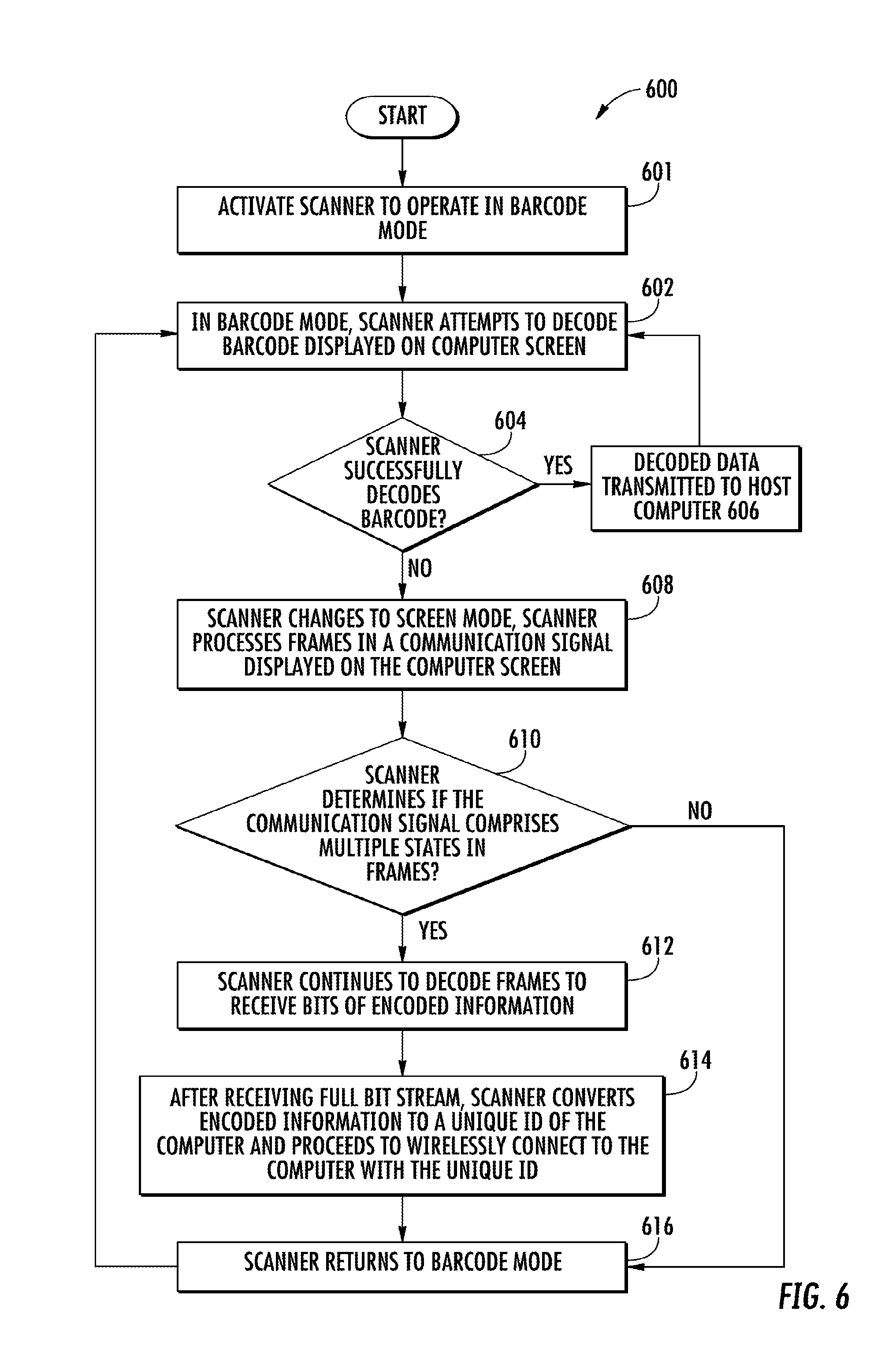
[0055] FIG. 6 is a flow diagram 600 illustrating another method of receiving at a scanner the communication sequence that includes encoded information. The method may comprises the steps of:
[0056] Activate a scanner to operate in barcode mode. (step 601)
[0057] In the barcode mode, the scanner attempts to decode a barcode displayed on computer screen. (step 602) For one embodiment of decoding, the scanner scans for contrast areas and then determines edges between high and low contrast.
[0058] Does the scanner successfully decode the barcode? (step 604) If the scanner does not successfully decode the barcode: (i) change the operation of the scanner to a screen mode and process a plurality of frames in a communication sequence displayed on the computer screen. (step 608) In one embodiment, several frames (e.g., six) are processed by averaging pixels.
[0059] The scanner determines if the communication sequence comprises multiple states in the frames of the communication sequence. (step 610) In one embodiment, there may be three states corresponding to black, gray, and white. In another embodiment there may be more than three states.
[0060] If the communication sequence comprises multiple states, the scanner continues to decode the plurality of frames comprising bits of encoded information. (step 612) After receiving and decoding a full bit stream, the scanner converts the encoded information to a unique ID of the computer, and then wirelessly connects to the computer using the unique ID. (step 614) The wireless connection may utilize Bluetooth technology. Subsequently, the operation of the scanner returns to the barcode mode. A full bit stream comprises all the bits contained between prolonged gray states that last for multiple frames. (step 616) In the barcode mode, if the scanner successfully decodes the barcode, the scanner transmits the decoded barcode to a host computer, and then the scanner repeats the operation in the barcode mode by attempting to decode another barcode. (steps 602, 604, 606)
[0061] In the screen mode, if the communication sequence does not comprise multiple states, the operation of the scanner returns to barcode mode. (steps 610, 616)
[0062] In summary, the computer may transmit its communication sequence with a unique identifier continuously in a loop in a designated area such as in the lower right corner of the computer screen. The user places the scanner in contact with the screen and makes an average reading of all or a portion of its sensor pixels during each frame of its scan time. The scanner records the bits and the long gray segment that indicates the start of the data until a full data transmission is obtained. The scanner may then unambiguously connect with the computer terminal, such as a CV61, using the acquired data. The present invention in a broad sense is a generic method of communication from a computer screen without the limitation of an in-focus optics system and in the presence of high environmental challenges such as direct sunlight or rain. The invention was inspired by observing the difficulties of a user in a package carrier environment when trying to read a bar code off the screen in the presence of direct sunlight. The present invention, therefore, is not limited to a specific application such as communicating a computer MAC address, but can be a method of communicating data for any purpose, including data collection.
[0063] The present invention allows the scanners already deployed to be used with only software modifications. With the present invention, a user may connect a common scanning device to a host computer in the presence of direct sunlight with a high confidence level of success.
[0064] To supplement the present disclosure, this application incorporates entirely by reference the following commonly assigned patents, patent application publications, and patent applications: [0065] U.S. Pat. Nos. 6,832,725; 7,128,266; [0066] 7,159,783; 7,413,127; [0067] 7,726,575; 8,294,969; [0068] 8,317,105; 8,322,622; [0069] 8,366,005; 8,371,507; [0070] 8,376,233; 8,381,979; [0071] 8,390,909; 8,408,464; [0072] 8,408,468; 8,408,469; [0073] 8,424,768; 8,448,863; [0074] 8,457,013; 8,459,557; [0075] 8,469,272; 8,474,712; [0076] 8,479,992; 8,490,877; [0077] 8,517,271; 8,523,076; [0078] 8,528,818; 8,544,737; [0079] 8,548,242; 8,548,420; [0080] 8,550,335; 8,550,354; [0081] 8,550,357; 8,556,174; [0082] 8,556,176; 8,556,177; [0083] 8,559,767; 8,599,957; [0084] 8,561,895; 8,561,903; [0085] 8,561,905; 8,565,107; [0086] 8,571,307; 8,579,200; [0087] 8,583,924; 8,584,945; [0088] 8,587,595; 8,587,697; [0089] 8,588,869; 8,590,789; [0090] 8,596,539; 8,596,542; [0091] 8,596,543; 8,599,271; [0092] 8,599,957; 8,600,158; [0093] 8,600,167; 8,602,309; [0094] 8,608,053; 8,608,071; [0095] 8,611,309; 8,615,487; [0096] 8,616,454; 8,621,123; [0097] 8,622,303; 8,628,013; [0098] 8,628,015; 8,628,016; [0099] 8,629,926; 8,630,491; [0100] 8,635,309; 8,636,200; [0101] 8,636,212; 8,636,215; [0102] 8,636,224; 8,638,806; [0103] 8,640,958; 8,640,960; [0104] 8,643,717; 8,646,692; [0105] 8,646,694; 8,657,200; [0106] 8,659,397; 8,668,149; [0107] 8,678,285; 8,678,286; [0108] 8,682,077; 8,687,282; [0109] 8,692,927; 8,695,880; [0110] 8,698,949; 8,717,494; [0111] 8,717,494; 8,720,783; [0112] 8,723,804; 8,723,904; [0113] 8,727,223; U.S. Pat. No. D702,237; [0114] U.S. Pat. Nos. 8,740,082; 8,740,085; [0115] 8,746,563; 8,750,445; [0116] 8,752,766; 8,756,059; [0117] 8,757,495; 8,760,563; [0118] 8,763,909; 8,777,108; [0119] 8,777,109; 8,779,898; [0120] 8,781,520; 8,783,573; [0121] 8,789,757; 8,789,758; [0122] 8,789,759; 8,794,520; [0123] 8,794,522; 8,794,525; [0124] 8,794,526; 8,798,367; [0125] 8,807,431; 8,807,432; [0126] 8,820,630; 8,822,848; [0127] 8,824,692; 8,824,696; [0128] 8,842,849; 8,844,822; [0129] 8,844,823; 8,849,019; [0130] 8,851,383; 8,854,633; [0131] 8,866,963; 8,868,421; [0132] 8,868,519; 8,868,802; [0133] 8,868,803; 8,870,074; [0134] 8,879,639; 8,880,426; [0135] 8,881,983; 8,881,987; [0136] 8,903,172; 8,908,995; [0137] 8,910,870; 8,910,875; [0138] 8,914,290; 8,914,788; [0139] 8,915,439; 8,915,444; [0140] 8,916,789; 8,918,250; [0141] 8,918,564; 8,925,818; [0142] 8,939,374; 8,942,480; [0143] 8,944,313; 8,944,327; [0144] 8,944,332; 8,950,678; [0145] 8,967,468; 8,971,346; [0146] 8,976,030; 8,976,368; [0147] 8,978,981; 8,978,983; [0148] 8,978,984; 8,985,456; [0149] 8,985,457; 8,985,459; [0150] 8,985,461; 8,988,578; [0151] 8,988,590; 8,991,704; [0152] 8,996,194; 8,996,384; [0153] 9,002,641; 9,007,368; [0154] 9,010,641; 9,015,513; [0155] 9,016,576; 9,022,288; [0156] 9,030,964; 9,033,240; [0157] 9,033,242; 9,036,054; [0158] 9,037,344; 9,038,911; [0159] 9,038,915; 9,047,098; [0160] 9,047,359; 9,047,420; [0161] 9,047,525; 9,047,531; [0162] 9,053,055; 9,053,378; [0163] 9,053,380; 9,058,526; [0164] 9,064,165; 9,064,167; [0165] 9,064,168; 9,064,254; [0166] 9,066,032; 9,070,032; [0167] U.S. Design Pat. No. D716,285; [0168] U.S. Design Pat. No. D723,560; [0169] U.S. Design Pat. No. D730,357; [0170] U.S. Design Pat. No. D730,901; [0171] U.S. Design Pat. No. D730,902; [0172] U.S. Design Pat. No. D733,112; [0173] U.S. Design Pat. No. D734,339; [0174] International Publication No. 2013/163789; [0175] International Publication No. 2013/173985; [0176] International Publication No. 2014/019130; [0177] International Publication No. 2014/110495; [0178] U.S. Patent Application Publication No. 2008/0185432; [0179] U.S. Patent Application Publication No. 2009/0134221; [0180] U.S. Patent Application Publication No. 2010/0177080; [0181] U.S. Patent Application Publication No. 2010/0177076; [0182] U.S. Patent Application Publication No. 2010/0177707; [0183] U.S. Patent Application Publication No. 2010/0177749; [0184] U.S. Patent Application Publication No. 2010/0265880; [0185] U.S. Patent Application Publication No. 2011/0202554; [0186] U.S. Patent Application Publication No. 2012/0111946; [0187] U.S. Patent Application Publication No. 2012/0168511; [0188] U.S. Patent Application Publication No. 2012/0168512; [0189] U.S. Patent Application Publication No. 2012/0193423; [0190] U.S. Patent Application Publication No. 2012/0203647; [0191] U.S. Patent Application Publication No. 2012/0223141; [0192] U.S. Patent Application Publication No. 2012/0228382; [0193] U.S. Patent Application Publication No. 2012/0248188; [0194] U.S. Patent Application Publication No. 2013/0043312; [0195] U.S. Patent Application Publication No. 2013/0082104; [0196] U.S. Patent Application Publication No. 2013/0175341; [0197] U.S. Patent Application Publication No. 2013/0175343; [0198] U.S. Patent Application Publication No. 2013/0257744; [0199] U.S. Patent Application Publication No. 2013/0257759; [0200] U.S. Patent Application Publication No. 2013/0270346; [0201] U.S. Patent Application Publication No. 2013/0287258; [0202] U.S. Patent Application Publication No. 2013/0292475; [0203] U.S. Patent Application Publication No. 2013/0292477; [0204] U.S. Patent Application Publication No. 2013/0293539; [0205] U.S. Patent Application Publication No. 2013/0293540; [0206] U.S. Patent Application Publication No. 2013/0306728; [0207] U.S. Patent Application Publication No. 2013/0306731; [0208] U.S. Patent Application Publication No. 2013/0307964; [0209] U.S. Patent Application Publication No. 2013/0308625; [0210] U.S. Patent Application Publication No. 2013/0313324; [0211] U.S. Patent Application Publication No. 2013/0313325; [0212] U.S. Patent Application Publication No. 2013/0342717; [0213] U.S. Patent Application Publication No. 2014/0001267; [0214] U.S. Patent Application Publication No. 2014/0008439; [0215] U.S. Patent Application Publication No. 2014/0025584; [0216] U.S. Patent Application Publication No. 2014/0034734; [0217] U.S. Patent Application Publication No. 2014/0036848; [0218] U.S. Patent Application Publication No. 2014/0039693; [0219] U.S. Patent Application Publication No. 2014/0042814; [0220] U.S. Patent Application Publication No. 2014/0049120; [0221] U.S. Patent Application Publication No. 2014/0049635; [0222] U.S. Patent Application Publication No. 2014/0061306; [0223] U.S. Patent Application Publication No. 2014/0063289; [0224] U.S. Patent Application Publication No. 2014/0066136; [0225] U.S. Patent Application Publication No. 2014/0067692; [0226] U.S. Patent Application Publication No. 2014/0070005; [0227] U.S. Patent Application Publication No. 2014/0071840; [0228] U.S. Patent Application Publication No. 2014/0074746; [0229] U.S. Patent Application Publication No. 2014/0076974; [0230] U.S. Patent Application Publication No. 2014/0078341; [0231] U.S. Patent Application Publication No. 2014/0078345; [0232] U.S. Patent Application Publication No. 2014/0097249; [0233] U.S. Patent Application Publication No. 2014/0098792; [0234] U.S. Patent Application Publication No. 2014/0100813; [0235] U.S. Patent Application Publication No. 2014/0103115; [0236] U.S. Patent Application Publication No. 2014/0104413; [0237] U.S. Patent Application Publication No. 2014/0104414; [0238] U.S. Patent Application Publication No. 2014/0104416; [0239] U.S. Patent Application Publication No. 2014/0104451; [0240] U.S. Patent Application Publication No. 2014/0106594; [0241] U.S. Patent Application Publication No. 2014/0106725; [0242] U.S. Patent Application Publication No. 2014/0108010; [0243] U.S. Patent Application Publication No. 2014/0108402; [0244] U.S. Patent Application Publication No. 2014/0110485; [0245] U.S. Patent Application Publication No. 2014/0114530; [0246] U.S. Patent Application Publication No. 2014/0124577; [0247] U.S. Patent Application Publication No. 2014/0124579; [0248] U.S. Patent Application Publication No. 2014/0125842; [0249] U.S. Patent Application Publication No. 2014/0125853; [0250] U.S. Patent Application Publication No. 2014/0125999; [0251] U.S. Patent Application Publication No. 2014/0129378; [0252] U.S. Patent Application Publication No. 2014/0131438; [0253] U.S. Patent Application Publication No. 2014/0131441; [0254] U.S. Patent Application Publication No. 2014/0131443; [0255] U.S. Patent Application Publication No. 2014/0131444; [0256] U.S. Patent Application Publication No. 2014/0131445; [0257] U.S. Patent Application Publication No. 2014/0131448; [0258] U.S. Patent Application Publication No. 2014/0133379; [0259] U.S. Patent Application Publication No. 2014/0136208; [0260] U.S. Patent Application Publication No. 2014/0140585; [0261] U.S. Patent Application Publication No. 2014/0151453; [0262] U.S. Patent Application Publication No. 2014/0152882; [0263] U.S. Patent Application Publication No. 2014/0158770; [0264] U.S. Patent Application Publication No. 2014/0159869; [0265] U.S. Patent Application Publication No. 2014/0166755; [0266] U.S. Patent Application Publication No. 2014/0166759; [0267] U.S. Patent Application Publication No. 2014/0168787; [0268] U.S. Patent Application Publication No. 2014/0175165; [0269] U.S. Patent Application Publication No. 2014/0175172; [0270] U.S. Patent Application Publication No. 2014/0191644; [0271] U.S. Patent Application Publication No. 2014/0191913; [0272] U.S. Patent Application Publication No. 2014/0197238; [0273] U.S. Patent Application Publication No. 2014/0197239; [0274] U.S. Patent Application Publication No. 2014/0197304; [0275] U.S. Patent Application Publication No. 2014/0214631; [0276] U.S. Patent Application Publication No. 2014/0217166; [0277] U.S. Patent Application Publication No. 2014/0217180; [0278] U.S. Patent Application Publication No. 2014/0231500; [0279] U.S. Patent Application Publication No. 2014/0232930; [0280] U.S. Patent Application Publication No. 2014/0247315; [0281] U.S. Patent Application Publication No. 2014/0263493; [0282] U.S. Patent Application Publication No. 2014/0263645; [0283] U.S. Patent Application Publication No. 2014/0267609; [0284] U.S. Patent Application Publication No. 2014/0270196; [0285] U.S. Patent Application Publication No. 2014/0270229; [0286] U.S. Patent Application Publication No. 2014/0278387; [0287] U.S. Patent Application Publication No. 2014/0278391; [0288] U.S. Patent Application Publication No. 2014/0282210; [0289] U.S. Patent Application Publication No. 2014/0284384; [0290] U.S. Patent Application Publication No. 2014/0288933; [0291] U.S. Patent Application Publication No. 2014/0297058; [0292] U.S. Patent Application Publication No. 2014/0299665; [0293] U.S. Patent Application Publication No. 2014/0312121; [0294] U.S. Patent Application Publication No. 2014/0319220; [0295] U.S. Patent Application Publication No. 2014/0319221; [0296] U.S. Patent Application Publication No. 2014/0326787; [0297] U.S. Patent Application Publication No. 2014/0332590; [0298] U.S. Patent Application Publication No. 2014/0344943; [0299] U.S. Patent Application Publication No. 2014/0346233; [0300] U.S. Patent Application Publication No. 2014/0351317; [0301] U.S. Patent Application Publication No. 2014/0353373; [0302] U.S. Patent Application Publication No. 2014/0361073; [0303] U.S. Patent Application Publication No. 2014/0361082; [0304] U.S. Patent Application Publication No. 2014/0362184; [0305] U.S. Patent Application Publication No. 2014/0363015; [0306] U.S. Patent Application Publication No. 2014/0369511; [0307] U.S. Patent Application Publication No. 2014/0374483; [0308] U.S. Patent Application Publication No. 2014/0374485; [0309] U.S. Patent Application Publication No. 2015/0001301; [0310] U.S. Patent Application Publication No. 2015/0001304; [0311] U.S. Patent Application Publication No. 2015/0003673; [0312] U.S. Patent Application Publication No. 2015/0009338; [0313] U.S. Patent Application Publication No. 2015/0009610; [0314] U.S. Patent Application Publication No. 2015/0014416; [0315] U.S. Patent Application Publication No. 2015/0021397; [0316] U.S. Patent Application Publication No. 2015/0028102; [0317] U.S. Patent Application Publication No. 2015/0028103; [0318] U.S. Patent Application Publication No. 2015/0028104; [0319] U.S. Patent Application Publication No. 2015/0029002; [0320] U.S. Patent Application Publication No. 2015/0032709; [0321] U.S. Patent Application Publication No. 2015/0039309; [0322] U.S. Patent Application Publication No. 2015/0039878; [0323] U.S. Patent Application Publication No. 2015/0040378; [0324] U.S. Patent Application Publication No. 2015/0048168; [0325] U.S. Patent Application Publication No. 2015/0049347; [0326] U.S. Patent Application Publication No. 2015/0051992; [0327] U.S. Patent Application Publication No. 2015/0053766; [0328] U.S. Patent Application Publication No. 2015/0053768; [0329] U.S. Patent Application Publication No. 2015/0053769; [0330] U.S. Patent Application Publication No. 2015/0060544; [0331] U.S. Patent Application Publication No. 2015/0062366; [0332] U.S. Patent Application Publication No. 2015/0063215; [0333] U.S. Patent Application Publication No. 2015/0063676; [0334] U.S. Patent Application Publication No. 2015/0069130; [0335] U.S. Patent Application Publication No. 2015/0071819; [0336] U.S. Patent Application Publication No. 2015/0083800; [0337] U.S. Patent Application Publication No. 2015/0086114; [0338] U.S. Patent Application Publication No. 2015/0088522; [0339] U.S. Patent Application Publication No. 2015/0096872; [0340] U.S. Patent Application Publication No. 2015/0099557; [0341] U.S. Patent Application Publication No. 2015/0100196; [0342] U.S. Patent Application Publication No. 2015/0102109; [0343] U.S. Patent Application Publication No. 2015/0115035; [0344] U.S. Patent Application Publication No. 2015/0127791; [0345] U.S. Patent Application Publication No. 2015/0128116; [0346] U.S. Patent Application Publication No. 2015/0129659; [0347] U.S. Patent Application Publication No. 2015/0133047; [0348] U.S. Patent Application Publication No. 2015/0134470; [0349] U.S. Patent Application Publication No. 2015/0136851; [0350] U.S. Patent Application Publication No. 2015/0136854; [0351] U.S. Patent Application Publication No. 2015/0142492; [0352] U.S. Patent Application Publication No. 2015/0144692; [0353] U.S. Patent Application Publication No. 2015/0144698; [0354] U.S. Patent Application Publication No. 2015/0144701; [0355] U.S. Patent Application Publication No. 2015/0149946; [0356] U.S. Patent Application Publication No. 2015/0161429; [0357] U.S. Patent Application Publication No. 2015/0169925; [0358] U.S. Patent Application Publication No. 2015/0169929; [0359] U.S. Patent Application Publication No. 2015/0178523; [0360] U.S. Patent Application Publication No. 2015/0178534; [0361] U.S. Patent Application Publication No. 2015/0178535; [0362] U.S. Patent Application Publication No. 2015/0178536; [0363] U.S. Patent Application Publication No. 2015/0178537;
[0364] U.S. Patent Application Publication No. 2015/0181093; [0365] U.S. Patent Application Publication No. 2015/0181109; [0366] U.S. patent application Ser. No. 13/367,978 for a Laser Scanning Module Employing an Elastomeric U-Hinge Based Laser Scanning Assembly, filed Feb. 7, 2012 (Feng et al.); [0367] U.S. patent application Ser. No. 29/458,405 for an Electronic Device, filed Jun. 19, 2013 (Fitch et al.); [0368] U.S. patent application Ser. No. 29/459,620 for an Electronic Device Enclosure, filed Jul. 2, 2013 (London et al.); [0369] U.S. patent application Ser. No. 29/468,118 for an Electronic Device Case, filed Sep. 26, 2013 (Oberpriller et al.); [0370] U.S. patent application Ser. No. 14/150,393 for Indicia-reader Having Unitary Construction Scanner, filed Jan. 8, 2014 (Colavito et al.); [0371] U.S. patent application Ser. No. 14/200,405 for Indicia Reader for Size-Limited Applications filed Mar. 7, 2014 (Feng et al.); [0372] U.S. patent application Ser. No. 14/231,898 for Hand-Mounted Indicia-Reading Device with Finger Motion Triggering filed Apr. 1, 2014 (Van Horn et al.); [0373] U.S. patent application Ser. No. 29/486,759 for an Imaging Terminal, filed Apr. 2, 2014 (Oberpriller et al.); [0374] U.S. patent application Ser. No. 14/257,364 for Docking System and Method Using Near Field Communication filed Apr. 21, 2014 (Showering); [0375] U.S. patent application Ser. No. 14/264,173 for Autofocus Lens System for Indicia Readers filed Apr. 29, 2014 (Ackley et al.); [0376] U.S. patent application Ser. No. 14/277,337 for MULTIPURPOSE OPTICAL READER, filed May 14, 2014 (Jovanovski et al.); [0377] U.S. patent application Ser. No. 14/283,282 for TERMINAL HAVING ILLUMINATION AND FOCUS CONTROL filed May 21, 2014 (Liu et al.); [0378] U.S. patent application Ser. No. 14/327,827 for a MOBILE-PHONE ADAPTER FOR ELECTRONIC TRANSACTIONS, filed Jul. 10, 2014 (Hejl); [0379] U.S. patent application Ser. No. 14/334,934 for a SYSTEM AND METHOD FOR INDICIA VERIFICATION, filed Jul. 18, 2014 (Hejl); [0380] U.S. patent application Ser. No. 14/339,708 for LASER SCANNING CODE SYMBOL READING SYSTEM, filed Jul. 24, 2014 (Xian et al.); [0381] U.S. patent application Ser. No. 14/340,627 for an AXIALLY REINFORCED FLEXIBLE SCAN ELEMENT, filed Jul. 25, 2014 (Rueblinger et al.); [0382] U.S. patent application Ser. No. 14/446,391 for MULTIFUNCTION POINT OF SALE APPARATUS WITH OPTICAL SIGNATURE CAPTURE filed Jul. 30, 2014 (Good et al.); [0383] U.S. patent application Ser. No. 14/452,697 for INTERACTIVE INDICIA READER, filed Aug. 6, 2014 (Todeschini); [0384] U.S. patent application Ser. No. 14/453,019 for DIMENSIONING SYSTEM WITH GUIDED ALIGNMENT, filed Aug. 6, 2014 (Li et al.); [0385] U.S. patent application Ser. No. 14/462,801 for MOBILE COMPUTING DEVICE WITH DATA COGNITION SOFTWARE, filed on Aug. 19, 2014 (Todeschini et al.); [0386] U.S. patent application Ser. No. 14/483,056 for VARIABLE DEPTH OF FIELD BARCODE SCANNER filed Sep. 10, 2014 (McCloskey et al.); [0387] U.S. patent application Ser. No. 14/513,808 for IDENTIFYING INVENTORY ITEMS IN A STORAGE FACILITY filed Oct. 14, 2014 (Singel et al.); [0388] U.S. patent application Ser. No. 14/519,195 for HANDHELD DIMENSIONING SYSTEM WITH FEEDBACK filed Oct. 21, 2014 (Laffargue et al.); [0389] U.S. patent application Ser. No. 14/519,179 for DIMENSIONING SYSTEM WITH MULTIPATH INTERFERENCE MITIGATION filed Oct. 21, 2014 (Thuries et al.); [0390] U.S. patent application Ser. No. 14/519,211 for SYSTEM AND METHOD FOR DIMENSIONING filed Oct. 21, 2014 (Ackley et al.); [0391] U.S. patent application Ser. No. 14/519,233 for HANDHELD DIMENSIONER WITH DATA-QUALITY INDICATION filed Oct. 21, 2014 (Laffargue et al.); [0392] U.S. patent application Ser. No. 14/519,249 for HANDHELD DIMENSIONING SYSTEM WITH MEASUREMENT-CONFORMANCE FEEDBACK filed Oct. 21, 2014 (Ackley et al.); [0393] U.S. patent application Ser. No. 14/527,191 for METHOD AND SYSTEM FOR RECOGNIZING SPEECH USING WILDCARDS IN AN EXPECTED RESPONSE filed Oct. 29, 2014 (Braho et al.); [0394] U.S. patent application Ser. No. 14/529,563 for ADAPTABLE INTERFACE FOR A MOBILE COMPUTING DEVICE filed Oct. 31, 2014 (Schoon et al.); [0395] U.S. patent application Ser. No. 14/529,857 for BARCODE READER WITH SECURITY FEATURES filed Oct. 31, 2014 (Todeschini et al.); [0396] U.S. patent application Ser. No. 14/398,542 for PORTABLE ELECTRONIC DEVICES HAVING A SEPARATE LOCATION TRIGGER UNIT FOR USE IN CONTROLLING AN APPLICATION UNIT filed Nov. 3, 2014 (Bian et al.); [0397] U.S. patent application Ser. No. 14/531,154 for DIRECTING AN INSPECTOR THROUGH AN INSPECTION filed Nov. 3, 2014 (Miller et al.); [0398] U.S. patent application Ser. No. 14/533,319 for BARCODE SCANNING SYSTEM USING WEARABLE DEVICE WITH EMBEDDED CAMERA filed Nov. 5, 2014 (Todeschini); [0399] U.S. patent application Ser. No. 14/535,764 for CONCATENATED EXPECTED RESPONSES FOR SPEECH RECOGNITION filed Nov. 7, 2014 (Braho et al.); [0400] U.S. patent application Ser. No. 14/568,305 for AUTO-CONTRAST VIEWFINDER FOR AN INDICIA READER filed Dec. 12, 2014 (Todeschini); [0401] U.S. patent application Ser. No. 14/573,022 for DYNAMIC DIAGNOSTIC INDICATOR GENERATION filed Dec. 17, 2014 (Goldsmith); [0402] U.S. patent application Ser. No. 14/578,627 for SAFETY SYSTEM AND METHOD filed Dec. 22, 2014 (Ackley et al.); [0403] U.S. patent application Ser. No. 14/580,262 for MEDIA GATE FOR THERMAL TRANSFER PRINTERS filed Dec. 23, 2014 (Bowles); [0404] U.S. patent application Ser. No. 14/590,024 for SHELVING AND PACKAGE LOCATING SYSTEMS FOR DELIVERY VEHICLES filed Jan. 6, 2015 (Payne); [0405] U.S. patent application Ser. No. 14/596,757 for SYSTEM AND METHOD FOR DETECTING BARCODE PRINTING ERRORS filed Jan. 14, 2015 (Ackley); [0406] U.S. patent application Ser. No. 14/416,147 for OPTICAL READING APPARATUS HAVING VARIABLE SETTINGS filed Jan. 21, 2015 (Chen et al.); [0407] U.S. patent application Ser. No. 14/614,706 for DEVICE FOR SUPPORTING AN ELECTRONIC TOOL ON A USER'S HAND filed Feb. 5, 2015 (Oberpriller et al.); [0408] U.S. patent application Ser. No. 14/614,796 for CARGO APPORTIONMENT TECHNIQUES filed Feb. 5, 2015 (Morton et al.); [0409] U.S. patent application Ser. No. 29/516,892 for TABLE COMPUTER filed Feb. 6, 2015 (Bidwell et al.); [0410] U.S. patent application Ser. No. 14/619,093 for METHODS FOR TRAINING A SPEECH RECOGNITION SYSTEM filed Feb. 11, 2015 (Pecorari); [0411] U.S. patent application Ser. No. 14/628,708 for DEVICE, SYSTEM, AND METHOD FOR DETERMINING THE STATUS OF CHECKOUT LANES filed Feb. 23, 2015 (Todeschini); [0412] U.S. patent application Ser. No. 14/630,841 for TERMINAL INCLUDING IMAGING ASSEMBLY filed Feb. 25, 2015 (Gomez et al.); [0413] U.S. patent application Ser. No. 14/635,346 for SYSTEM AND METHOD FOR RELIABLE STORE-AND-FORWARD DATA HANDLING BY ENCODED INFORMATION READING TERMINALS filed Mar. 2, 2015 (Sevier); [0414] U.S. patent application Ser. No. 29/519,017 for SCANNER filed Mar. 2, 2015 (Zhou et al.); [0415] U.S. patent application Ser. No. 14/405,278 for DESIGN PATTERN FOR SECURE STORE filed Mar. 9, 2015 (Zhu et al.); [0416] U.S. patent application Ser. No. 14/660,970 for DECODABLE INDICIA READING TERMINAL WITH COMBINED ILLUMINATION filed Mar. 18, 2015 (Kearney et al.); [0417] U.S. patent application Ser. No. 14/661,013 for REPROGRAMMING SYSTEM AND METHOD FOR DEVICES INCLUDING PROGRAMMING SYMBOL filed Mar. 18, 2015 (Soule et al.); [0418] U.S. patent application Ser. No. 14/662,922 for MULTIFUNCTION POINT OF SALE SYSTEM filed Mar. 19, 2015 (Van Horn et al.); [0419] U.S. patent application Ser. No. 14/663,638 for VEHICLE MOUNT COMPUTER WITH CONFIGURABLE IGNITION SWITCH BEHAVIOR filed Mar. 20, 2015 (Davis et al.); [0420] U.S. patent application Ser. No. 14/664,063 for METHOD AND APPLICATION FOR SCANNING A BARCODE WITH A SMART DEVICE WHILE CONTINUOUSLY RUNNING AND DISPLAYING AN APPLICATION ON THE SMART DEVICE DISPLAY filed Mar. 20, 2015 (Todeschini); [0421] U.S. patent application Ser. No. 14/669,280 for TRANSFORMING COMPONENTS OF A WEB PAGE TO VOICE PROMPTS filed Mar. 26, 2015 (Funyak et al.); [0422] U.S. patent application Ser. No. 14/674,329 for AIMER FOR BARCODE SCANNING filed Mar. 31, 2015 (Bidwell); [0423] U.S. patent application Ser. No. 14/676,109 for INDICIA READER filed Apr. 1, 2015 (Huck); [0424] U.S. patent application Ser. No. 14/676,327 for DEVICE MANAGEMENT PROXY FOR SECURE DEVICES filed Apr. 1, 2015 (Yeakley et al.); [0425] U.S. patent application Ser. No. 14/676,898 for NAVIGATION SYSTEM CONFIGURED TO INTEGRATE MOTION SENSING DEVICE INPUTS filed Apr. 2, 2015 (Showering); [0426] U.S. patent application Ser. No. 14/679,275 for DIMENSIONING SYSTEM CALIBRATION SYSTEMS AND METHODS filed Apr. 6, 2015 (Laffargue et al.); [0427] U.S. patent application Ser. No. 29/523,098 for HANDLE FOR A TABLET COMPUTER filed Apr. 7, 2015 (Bidwell et al.); [0428] U.S. patent application Ser. No. 14/682,615 for SYSTEM AND METHOD FOR POWER MANAGEMENT OF MOBILE DEVICES filed Apr. 9, 2015 (Murawski et al.); [0429] U.S. patent application Ser. No. 14/686,822 for MULTIPLE PLATFORM SUPPORT SYSTEM AND METHOD filed Apr. 15, 2015 (Qu et al.); [0430] U.S. patent application Ser. No. 14/687,289 for SYSTEM FOR COMMUNICATION VIA A PERIPHERAL HUB filed Apr. 15, 2015 (Kohtz et al.); [0431] U.S. patent application Ser. No. 29/524,186 for SCANNER filed Apr. 17, 2015 (Zhou et al.); [0432] U.S. patent application Ser. No. 14/695,364 for MEDICATION MANAGEMENT SYSTEM filed Apr. 24, 2015 (Sewell et al.); [0433] U.S. patent application Ser. No. 14/695,923 for SECURE UNATTENDED NETWORK AUTHENTICATION filed Apr. 24, 2015 (Kubler et al.); [0434] U.S. patent application Ser. No. 29/525,068 for TABLET COMPUTER WITH REMOVABLE SCANNING DEVICE filed Apr. 27, 2015 (Schulte et al.); [0435] U.S. patent application Ser. No. 14/699,436 for SYMBOL READING SYSTEM HAVING PREDICTIVE DIAGNOSTICS filed Apr. 29, 2015 (Nahill et al.); [0436] U.S. patent application Ser. No. 14/702,110 for SYSTEM AND METHOD FOR REGULATING BARCODE DATA INJECTION INTO A RUNNING APPLICATION ON A SMART DEVICE filed May 1, 2015 (Todeschini et al.); [0437] U.S. patent application Ser. No. 14/702,979 for TRACKING BATTERY CONDITIONS filed May 4, 2015 (Young et al.); [0438] U.S. patent application Ser. No. 14/704,050 for INTERMEDIATE LINEAR POSITIONING filed May 5, 2015 (Charpentier et al.); [0439] U.S. patent application Ser. No. 14/705,012 for HANDS-FREE HUMAN MACHINE INTERFACE RESPONSIVE TO A DRIVER OF A VEHICLE filed May 6, 2015 (Fitch et al.); [0440] U.S. patent application Ser. No. 14/705,407 for METHOD AND SYSTEM TO PROTECT SOFTWARE-BASED NETWORK-CONNECTED DEVICES FROM ADVANCED PERSISTENT THREAT filed May 6, 2015 (Hussey et al.); [0441] U.S. patent application Ser. No. 14/707,037 for SYSTEM AND METHOD FOR DISPLAY OF INFORMATION USING A VEHICLE-MOUNT COMPUTER filed May 8, 2015 (Chamberlin); [0442] U.S. patent application Ser. No. 14/707,123 for APPLICATION INDEPENDENT DEX/UCS INTERFACE filed May 8, 2015 (Pape); [0443] U.S. patent application Ser. No. 14/707,492 for METHOD AND APPARATUS FOR READING OPTICAL INDICIA USING A PLURALITY OF DATA SOURCES filed May 8, 2015 (Smith et al.); [0444] U.S. patent application Ser. No. 14/710,666 for PRE-PAID USAGE SYSTEM FOR ENCODED INFORMATION READING TERMINALS filed May 13, 2015 (Smith); [0445] U.S. patent application Ser. No. 29/526,918 for CHARGING BASE filed May 14, 2015 (Fitch et al.); [0446] U.S. patent application Ser. No. 14/715,672 for AUGUMENTED REALITY ENABLED HAZARD DISPLAY filed May 19, 2015 (Venkatesha et al.); [0447] U.S. patent application Ser. No. 14/715,916 for EVALUATING IMAGE VALUES filed May 19, 2015 (Ackley); [0448] U.S. patent application Ser. No. 14/722,608 for INTERACTIVE USER INTERFACE FOR CAPTURING A DOCUMENT IN AN IMAGE SIGNAL filed May 27, 2015 (Showering et al.); [0449] U.S. patent application Ser. No. 29/528,165 for IN-COUNTER BARCODE SCANNER filed May 27, 2015 (Oberpriller et al.); [0450] U.S. patent application Ser. No. 14/724,134 for ELECTRONIC DEVICE WITH WIRELESS PATH SELECTION CAPABILITY filed May 28, 2015 (Wang et al.); [0451] U.S. patent application Ser. No. 14/724,849 for METHOD OF PROGRAMMING THE DEFAULT CABLE INTERFACE SOFTWARE IN AN INDICIA READING DEVICE filed May 29, 2015 (Barten); [0452] U.S. patent application Ser. No. 14/724,908 for IMAGING APPARATUS HAVING IMAGING ASSEMBLY filed May 29, 2015 (Barber et al.); [0453] U.S. patent application Ser. No. 14/725,352 for APPARATUS AND METHODS FOR MONITORING ONE OR MORE PORTABLE DATA TERMINALS (Caballero et al.); [0454] U.S. patent application Ser. No. 29/528,590 for ELECTRONIC DEVICE filed May 29, 2015 (Fitch et al.); [0455] U.S. patent application Ser. No. 29/528,890 for MOBILE COMPUTER HOUSING filed Jun. 2, 2015 (Fitch et al.); [0456] U.S. patent application Ser. No. 14/728,397 for DEVICE MANAGEMENT USING VIRTUAL INTERFACES CROSS-REFERENCE TO RELATED APPLICATIONS filed Jun. 2, 2015 (Caballero); [0457] U.S. patent application Ser. No. 14/732,870 for DATA COLLECTION MODULE AND SYSTEM filed Jun. 8, 2015 (Powilleit); [0458] U.S. patent application Ser. No. 29/529,441 for INDICIA READING DEVICE filed Jun. 8, 2015 (Zhou et al.); [0459] U.S. patent application Ser. No. 14/735,717 for INDICIA-READING SYSTEMS HAVING AN INTERFACE WITH A USER'S NERVOUS SYSTEM filed Jun. 10, 2015 (Todeschini); [0460] U.S. patent application Ser. No. 14/738,038 for METHOD OF AND SYSTEM FOR DETECTING OBJECT WEIGHING INTERFERENCES filed Jun. 12, 2015 (Amundsen et al.); [0461] U.S. patent application Ser. No. 14/740,320 for TACTILE SWITCH FOR A MOBILE ELECTRONIC DEVICE filed Jun. 16, 2015 (Bandringa); [0462] U.S. patent application Ser. No. 14/740,373 for CALIBRATING A VOLUME DIMENSIONER filed Jun. 16, 2015 (Ackley et al.); [0463] U.S. patent application Ser. No. 14/742,818 for INDICIA READING SYSTEM EMPLOYING DIGITAL GAIN CONTROL filed Jun. 18, 2015 (Xian et al.); [0464] U.S. patent application Ser. No. 14/743,257 for WIRELESS MESH POINT PORTABLE DATA TERMINAL filed Jun. 18, 2015 (Wang et al.); [0465] U.S. patent application Ser. No. 29/530,600 for CYCLONE filed Jun. 18, 2015 (Vargo et al); [0466] U.S. patent application Ser. No. 14/744,633 for IMAGING APPARATUS COMPRISING IMAGE SENSOR ARRAY HAVING SHARED GLOBAL SHUTTER CIRCUITRY filed Jun. 19, 2015 (Wang); [0467] U.S. patent application Ser. No. 14/744,836 for CLOUD-BASED SYSTEM FOR READING OF DECODABLE INDICIA filed Jun. 19, 2015 (Todeschini et al.); [0468] U.S. patent application Ser. No. 14/745,006 for SELECTIVE OUTPUT OF DECODED MESSAGE DATA filed Jun. 19, 2015 (Todeschini et al.); [0469] U.S. patent application Ser. No. 14/747,197 for OPTICAL PATTERN PROJECTOR filed Jun. 23, 2015 (Thuries et al.); [0470] U.S. patent application Ser. No. 14/747,490 for DUAL-PROJECTOR THREE-DIMENSIONAL SCANNER filed Jun. 23, 2015 (Jovanovski et al.); and [0471] U.S. patent application Ser. No. 14/748,446 for CORDLESS INDICIA READER WITH A MULTIFUNCTION COIL FOR WIRELESS CHARGING AND EAS DEACTIVATION, filed Jun. 24, 2015 (Xie et al.).
[0472] In the specification and/or figures, typical embodiments of the invention have been disclosed. The present invention is not limited to such exemplary embodiments. The use of the term "and/or" includes any and all combinations of one or more of the associated listed items. The figures are schematic representations and so are not necessarily drawn to scale. Unless otherwise noted, specific terms have been used in a generic and descriptive sense and not for purposes of limitation.
* * * * *
D00000
D00001
D00002
D00003
D00004
D00005
D00006
D00007
XML
uspto.report is an independent third-party trademark research tool that is not affiliated, endorsed, or sponsored by the United States Patent and Trademark Office (USPTO) or any other governmental organization. The information provided by uspto.report is based on publicly available data at the time of writing and is intended for informational purposes only.
While we strive to provide accurate and up-to-date information, we do not guarantee the accuracy, completeness, reliability, or suitability of the information displayed on this site. The use of this site is at your own risk. Any reliance you place on such information is therefore strictly at your own risk.
All official trademark data, including owner information, should be verified by visiting the official USPTO website at www.uspto.gov. This site is not intended to replace professional legal advice and should not be used as a substitute for consulting with a legal professional who is knowledgeable about trademark law.