Electronic Temperature Safety Control for a Heating Element
Moon; Jung S. ; et al.
U.S. patent application number 16/049247 was filed with the patent office on 2019-05-23 for electronic temperature safety control for a heating element. The applicant listed for this patent is NuWave LLC. Invention is credited to Byung Gab Choi, Luo Fei, Li Xiang Jun, James Moon, Jung S. Moon, Zeng Qing Ping, Kim Jong Rok.
| Application Number | 20190155320 16/049247 |
| Document ID | / |
| Family ID | 66533956 |
| Filed Date | 2019-05-23 |


| United States Patent Application | 20190155320 |
| Kind Code | A1 |
| Moon; Jung S. ; et al. | May 23, 2019 |
Electronic Temperature Safety Control for a Heating Element
Abstract
A temperature control system for appliances, such as an electric grill, air fryer, vacuum blender, convection oven, induction cooker (e.g., wok), coffeemaker, etc. The control system comprises digital circuitry for controlling temperature of the appliance, and includes a first safety component in the circuitry for stopping the heating function at a threshold parameter, such as a maximum temperature, and a second safety component in the circuitry for stopping the heating function at a second threshold temperature if the first safety component fails at the first threshold temperature. The first and second safety components, preferably switches or fuses, are connected in series to establish a redundant safety mechanism.
| Inventors: | Moon; Jung S.; (Long Grove, IL) ; Choi; Byung Gab; (Lake Villa, IL) ; Moon; James; (Vernon Hills, IL) ; Jun; Li Xiang; (Foshan City, CN) ; Ping; Zeng Qing; (Shanwel City, CN) ; Rok; Kim Jong; (Seoul, KR) ; Fei; Luo; (Foshan City, CN) | ||||||||||
| Applicant: |
|
||||||||||
|---|---|---|---|---|---|---|---|---|---|---|---|
| Family ID: | 66533956 | ||||||||||
| Appl. No.: | 16/049247 | ||||||||||
| Filed: | July 30, 2018 |
Related U.S. Patent Documents
| Application Number | Filing Date | Patent Number | ||
|---|---|---|---|---|
| 62538450 | Jul 28, 2017 | |||
| Current U.S. Class: | 1/1 |
| Current CPC Class: | G05D 23/24 20130101; F24C 7/087 20130101; H05B 1/0202 20130101; H05B 1/0252 20130101; G05B 19/042 20130101; G05B 2219/2613 20130101 |
| International Class: | G05D 23/24 20060101 G05D023/24; F24C 7/08 20060101 F24C007/08; H05B 1/02 20060101 H05B001/02; G05B 19/042 20060101 G05B019/042 |
Claims
1. A temperature control system for appliances, the control system comprising: a housing; a heating element which couples to an appliance for heating a food or liquid; circuitry for digitally controlling a heating function in the heating element, the circuitry being positioned within the housing; wherein the circuitry comprises: a first safety component for stopping the heating function of the heating element at a first threshold parameter; and a second safety component for stopping the heating function of the heating element at a second threshold parameter, wherein the first and second safety components are connected in series and the second safety component is used only when the first safety component fails to stop the heating function at the first threshold parameter.
2. The temperature control system of claim 1, wherein the first and second safety components are switches or fuses and the first and second threshold parameters are maximum temperature levels.
3. The temperature control system of claim 2, wherein the heating element is for an appliance selected from one of either a convection oven, a coffeemaker, an induction wok, a skillet, a deep fryer, an air fryer, a vacuum blender, and an electric grill.
4. The temperature control system of claim 1, wherein the heating element comprises a digital NTC sensor.
5. The temperature control system of claim 2, wherein the housing comprises a detachable power cord which plugs into the appliance.
6. The temperature control system of claim 2, wherein the housing comprises a fixed control panel.
7. A method for controlling a cooking appliance comprising the steps of: providing a heating surface for transferring heat to a food or liquid; coupling a heating element to the heating surface, wherein the heating element provides a heating function to heat the heating surface; providing digital control circuitry coupled to the heating element, wherein the circuitry comprises: a first safety component for stopping the heating function of the heating element at a first threshold parameter; and a second safety component for stopping the heating function of the heating element at a second threshold parameter, wherein the first and second safety components are connected in series and the second safety component is used only when the first safety component fails to stop the heating function at the first threshold parameter.
Description
RELATED APPLICATION
[0001] The present application claims the filing priority of U.S. Provisional Application No. 62/538,450 titled "Electronic Temperature Safety Control For A Heating Element" filed on Jul. 28, 2017 (the '450 application). The '450 application is hereby incorporated herein in its entirety.
TECHNICAL FIELD OF THE INVENTION
[0002] The present invention relates to control system circuitry for household appliances. Specifically, the invention relates to safety control circuitry which prevents overheating due to a component failure.
BACKGROUND OF THE INVENTION
[0003] It is not uncommon for manufactured electronic components to fail in use. Typically, the consequences of failure are not severe. However, with some electronic components, failure may have far more significant costs, including injury to a user. This can be particularly true where the appliance has a heating element where failure can lead to personal injury or property damage.
[0004] Practically speaking, eventually all electronic systems and/or components will fail. Most electronic components far outlast the devices into which they are installed. Accordingly, manufacturing defects might account for a majority of early component failures.
[0005] Until the invention of the present application, these and other problems in the prior art have gone either unnoticed or unsolved by those skilled in the art. The present invention provides control system circuitry which is capable of performing multiple functions with associated electronic devices/appliances without sacrificing functionality, safety or affordability.
SUMMARY OF THE INVENTION
[0006] There is disclosed herein an improved safety control system for electronic devices which avoids the disadvantages of prior systems while affording additional operating advantages.
[0007] Generally speaking, the control system is for appliances, such as an electric grill, skillet, air fryer, vacuum blender, convection oven, induction cooker (e.g., wok), coffeemaker, etc. The control system comprises digital circuitry for accurately controlling temperature operation of the appliance, including a thermostat, a first safety component in the circuitry for stopping the heating function, such as the indirect heating of air or a liquid through heating of an element (e.g., a heating coil), at a threshold parameter, such as a maximum temperature, and a second safety component in the circuitry for stopping the heating function if the first safety component fails after the threshold parameter. The first and second safety components, preferably switches or fuses, are connected in series to establish a redundant safety mechanism.
[0008] These and other aspects of the invention may be understood more readily from the following description and the appended drawings.
BRIEF DESCRIPTION OF THE DRAWINGS
[0009] For the purpose of facilitating an understanding of the subject matter sought to be protected, there are illustrated in the accompanying drawings, embodiments thereof, from an inspection of which, when considered in connection with the following description, the subject matter sought to be protected, its construction and operation, and many of its advantages should be readily understood and appreciated.
[0010] FIG. 1 is a schematic illustrating a configuration for an embodiment of the dual safety switch/fuse mechanism for a coffee maker;
[0011] FIGS. 2 and 3 show a heating element (coil) around dual fuses used in the electronics of a cooking appliance, such as an electric wok or similar cooking surface, to prevent overheating;
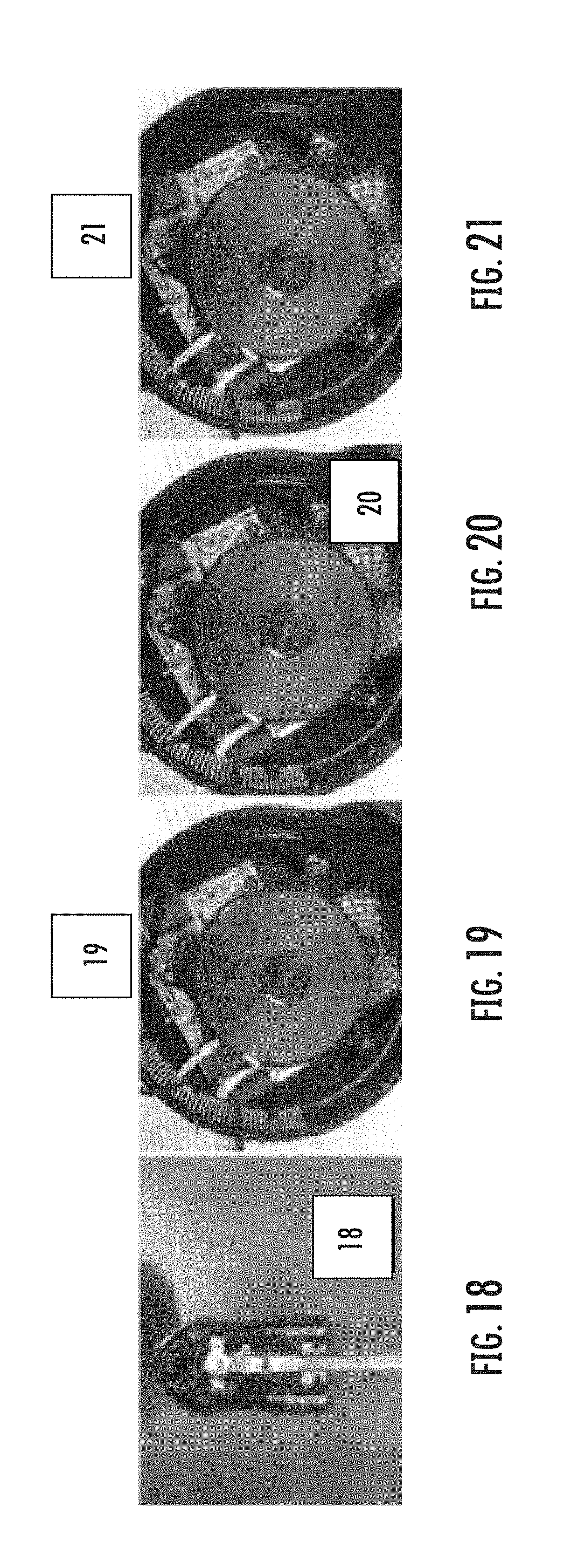
[0012] FIGS. 4-9 and 18 show prior art analog temperature controls for a heating element without any safety mechanism;
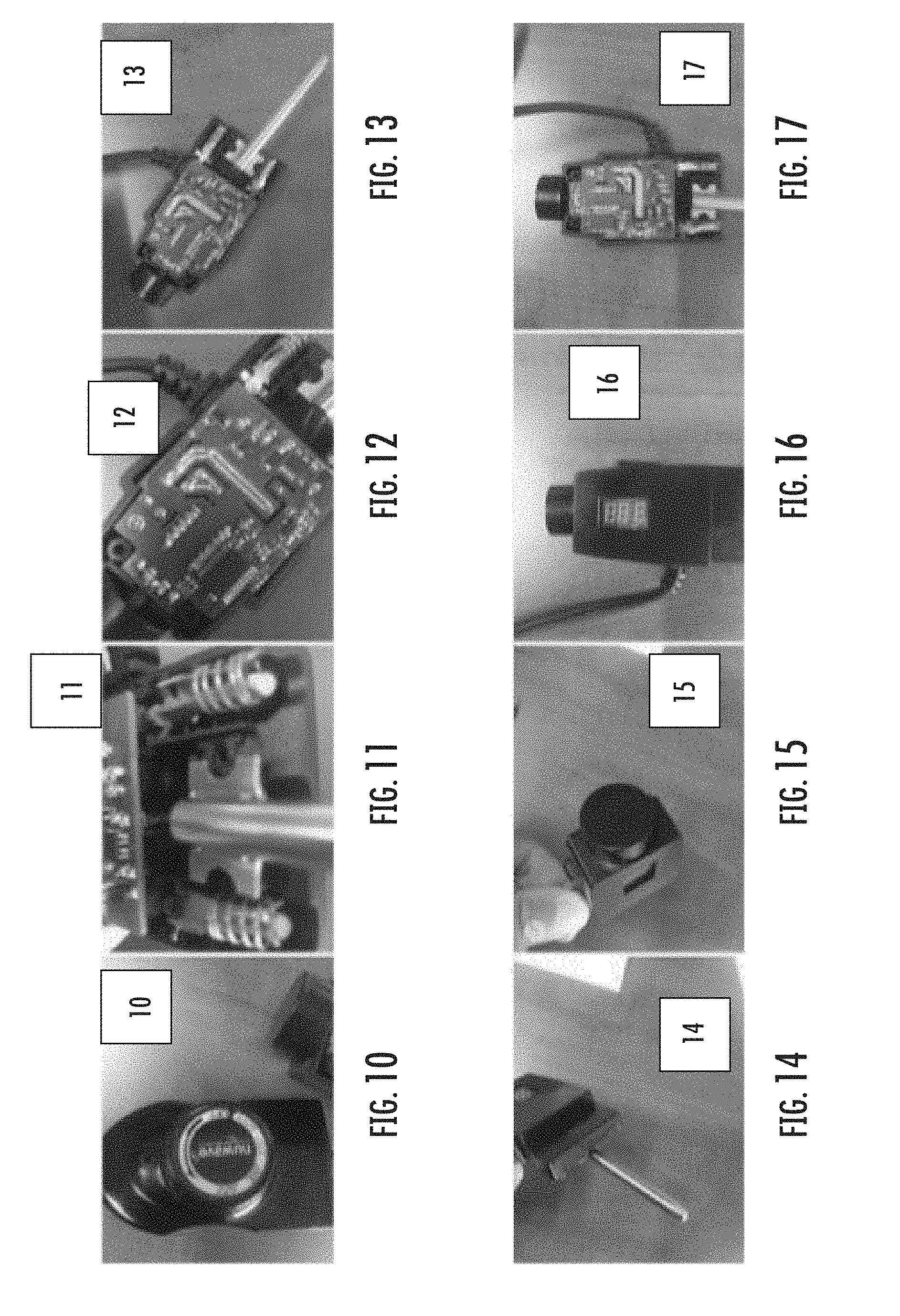
[0013] FIGS. 10-13 and 17 show a circuit board having a safety mechanism as used in a digital temperature control heating element;
[0014] FIGS. 14-16 show an exterior of a digital temperature control, including an adjustment knob and temperature display, as used on a heating element; and
[0015] FIGS. 19-21 show dual fuses used in the electronics of a cooking appliance, such as an electric grill, to prevent overheating.
DETAILED DESCRIPTION OF THE INVENTION
[0016] While this invention is susceptible of embodiments in many different forms, there is shown in the attached drawings and will herein be described in detail at least one preferred embodiment of the invention with the understanding that the present disclosure is to be considered as an exemplification of the principles of the invention and is not intended to limit the broad aspect of the invention to any of the specific embodiments illustrated.
[0017] Referring to FIGS. 1-3, 10-17 and 19-21, there is illustrated temperature control circuitry. The particular illustrated circuitry is for appliances. Specifically, the control system is for operation of appliances, such as an electric grill, air fryer, vacuum blender, convection oven, induction cooker (e.g., wok), coffeemaker, etc. Most specifically, the control system comprises circuitry for controlling a temperature of the appliance, and includes a first safety component in the circuitry for stopping the heating function at a threshold parameter, such as a maximum temperature, and a second safety component in the circuitry for stopping the heating function in the event the first safety component fails before reaching the desired threshold parameter. The first and second safety components, preferably electric switches or fuses, are connected in series to establish a redundant safety mechanism.
[0018] In a preferred embodiment, a digital temperature control includes a rigid housing for encasing control circuitry, and an AC power cord and a conductive connector extending from opposing ends of the control housing. The conductive connector is a hollow component which includes three sensor wires extended into the hollow connector toward the tip. The three sensor wires lead back into the housing and attach to the circuitry therein. A first of the wires is connected to a digital negative temperature coefficient (NTC) sensor in the housing of the control. A second of the wires connects to a first safety fuse/switch, while the second wire connects to a second safety fuse/switch. Generally, the NTC has a maximum temperature of about 425.degree. F., with an accuracy of .+-.5.degree. F. However, the maximum temperature of the NTC can vary depending on the application. For purposes of this invention, the first switch is intended to shut-down power to the appliance if a sensed temperature reaches past the maximum temperature, indicating failure of the NTC sensor. By way of example only, if the maximum temperature of the NTC is configured to be about 425.degree. F., with an accuracy of .+-.5.degree. F., and the sensed temperature reaches past the set temperature of 425.degree. F., about 430.degree. F. (.+-.5.degree. F.), the first switch will automatically shut-down power to the appliance as a safety mechanism. The second switch will shut-down power if the sensed temperature continues to reach higher than the set maximum temperature, and the first switch fails to shut-down power, indicating failure of the first switch.
[0019] The matter set forth in the foregoing description and accompanying drawings is offered by way of illustration only and not as a limitation. While particular embodiments have been shown and described, it will be apparent to those skilled in the art that changes and modifications may be made without departing from the broader aspects of applicants' contribution. The actual scope of the protection sought is intended to be defined in the following claims when viewed in their proper perspective based on the prior art.
* * * * *
D00000
D00001
D00002
D00003
D00004
XML
uspto.report is an independent third-party trademark research tool that is not affiliated, endorsed, or sponsored by the United States Patent and Trademark Office (USPTO) or any other governmental organization. The information provided by uspto.report is based on publicly available data at the time of writing and is intended for informational purposes only.
While we strive to provide accurate and up-to-date information, we do not guarantee the accuracy, completeness, reliability, or suitability of the information displayed on this site. The use of this site is at your own risk. Any reliance you place on such information is therefore strictly at your own risk.
All official trademark data, including owner information, should be verified by visiting the official USPTO website at www.uspto.gov. This site is not intended to replace professional legal advice and should not be used as a substitute for consulting with a legal professional who is knowledgeable about trademark law.