Structure And Manufacturing Method Of Holographic Optical Elements
Ishii; Fusao ; et al.
U.S. patent application number 16/252619 was filed with the patent office on 2019-05-23 for structure and manufacturing method of holographic optical elements. The applicant listed for this patent is Fusao Ishii, NTT DOCOMO, Inc.. Invention is credited to Yuji Aburakawa, Fusao Ishii, Mikiko Nakanishi, Kazuhiko Takahashi.
| Application Number | 20190155216 16/252619 |
| Document ID | / |
| Family ID | 66534427 |
| Filed Date | 2019-05-23 |


View All Diagrams
| United States Patent Application | 20190155216 |
| Kind Code | A1 |
| Ishii; Fusao ; et al. | May 23, 2019 |
STRUCTURE AND MANUFACTURING METHOD OF HOLOGRAPHIC OPTICAL ELEMENTS
Abstract
Manufacturing methods are disclosed to produce a seamless hologram using a free-form-lens enabling arbitrary adjustment of diffraction angle and also a thick hologram made of transparent inorganic materials and heat and UV resistant is disclosed.
| Inventors: | Ishii; Fusao; (Pittsburg, PA) ; Nakanishi; Mikiko; (Tokyo, JP) ; Takahashi; Kazuhiko; (Tokyo, JP) ; Aburakawa; Yuji; (Tokyo, JP) | ||||||||||
| Applicant: |
|
||||||||||
|---|---|---|---|---|---|---|---|---|---|---|---|
| Family ID: | 66534427 | ||||||||||
| Appl. No.: | 16/252619 | ||||||||||
| Filed: | January 19, 2019 |
Related U.S. Patent Documents
| Application Number | Filing Date | Patent Number | ||
|---|---|---|---|---|
| 14756589 | Sep 21, 2015 | |||
| 16252619 | ||||
| 62071310 | Sep 20, 2014 | |||
| 14756589 | ||||
| 62619902 | Jan 21, 2018 | |||
| Current U.S. Class: | 1/1 |
| Current CPC Class: | G02B 2003/0093 20130101; G02B 27/0955 20130101; G02B 3/02 20130101; G03H 1/024 20130101; G02B 5/32 20130101; G02B 27/10 20130101; G02B 27/30 20130101; G03B 21/62 20130101; G03H 2260/12 20130101; G03H 2001/0439 20130101; G03B 21/142 20130101 |
| International Class: | G03H 1/02 20060101 G03H001/02; G03B 21/62 20060101 G03B021/62; G03B 21/14 20060101 G03B021/14; G02B 27/10 20060101 G02B027/10; G02B 27/30 20060101 G02B027/30; G02B 27/09 20060101 G02B027/09 |
Claims
1. A see-through display comprising a display device and a projection lens system which projects the image of said display device a combiner which integrates a real image in front of a viewer and the projected image and a hologram on the combiner comprising a photopolymer wherein the photopolymer exposed for recording with two coherent beams and at least one of the beams is focused on the photopolymer with at least one free-form lens and the entire viewing surface of the photopolymer is exposed seamlessly by the free-form lens
2. The see-through display of claim-1 wherein the hologram is exposed with at least three colors.
3. The see-through display of claim-1 wherein one of recording beams is collimated.
4. The see-through display of claim-1 wherein the two recording beams are combined with a beam splitter,
5. A manufacturing method having the steps of: calculating a function which enables to know the diffraction angle of hologram to maximize the resolution of image of combiner of see-through display and calculating the tilt angle of micro stripe in the hologram and calculating the angles of two recording beams so that the middle angle between said two beams coincide with said tilt angle of micro stripe in the hologram and design at least one tree-form-lens so that the incident beams to the hologram coincide with said angles of two recording beams.
6. A see-through display comprising a display device and a projection lens system which projects the image of said display device and a combiner which integrates a real image in front of a viewer and the projected image and a hologram on the combiner wherein a hologram is made of transparent and inorganic material comprising a transparent substrate and at least two patterned layers of inorganic material whose refractive indices differ from that of said substrate and the patterned layers have a periodical structure and diffract incident light whose incident angle and wavelength and the pitch of the periodical structure meet Bragg's law.
7. The see-through display of claim-6 wherein the substrate is made of oxide and substantially transparent.
8. The see-through display of claim-6 wherein the patterned layers are made of nitride and substantially transparent.
9. The see-through display of claim-6 wherein the patterned layers are at least 2 microns thick.
Description
CROSS REFERENCE TO RELATED APPLICATIONS
[0001] This application is Non-Provisional Application and claim the Priority Date of a previously filed Provisional Application 62/6 9,902 filed on Jan. 21, 2018. Provisional Application 62/619,902 is a Continuation in Part (CIP) application of Patent Application 14/756589 filed on Sep. 21, 2015, which is a Non-Provisional Patent Application of a Provisional Application 62/071310 filed on Sep. 20, 2014.
TECHNICAL FIELD
[0002] This invention relates to a structure and manufacturing method of holographic optical elements (HOE) enabling more accurate fabrication by the utilization of Free-From-Lens for recording of per patterns. Another structure of thick hologram is disclosed by which can be manufactured by the use of lithography and thin film processes.
BACKGROUND OF THE INVENTION
[0003] Holographic Optical Elements, hereafter HOE, are becoming very important for new displays such as wearable displays, eye-glass displays and short distance projection displays. The structure of hologram is shown in. FIG. 2, wherein areas with higher refractive index (the stripe shaped area marked as 2001) and areas with lower refractive index (marked as 2002) are interleaved and create a periodical structure. The angle of these stripes determines the deflection angle of outgoing beams (marked as 2005) from the incident light beam (2004). The pitch or stripes (marked as 2003) determines the wavelength of diffracted beams. HOE is capable to diffract only a light beam with specific wavelength and incident direction. This performance cannot be obtained from regular geometric optics and is very useful for some applications such as Augmented Reality (AR) and wearable displays. A typical fabrication method of HOE is to record stripe patterns with the interference of coherent light beams as shown in FIG. 1. Tow coherent beams (1001 and 1002) are lead to a film of photopolymer (2003). The interference between the two beams create stripe patterns as shown at (1003) in FIG. 1. The refractive index of the photopolymer changes often proportional to the intensity of the exposed light, which are periodic and the direction of tilted stripe (marked as 2006 in FIG. 2) is the middle angle of the two incident beams. Thus, the angle of stripe can be controlled precisely, if the directions of the two incident beams can be controlled accurately.
[0004] Conventional manufacturing methods are shown in FIG. 3 and FIG. 4. The example of FIG. 3 is to record transmissive HOE (transmissive means an incident beam (illumination beam) enters at a first surface of HOE and its diffracted outgoing beam (playback beam) is emitted from the second surface) using two recording beams in the same side. The example of FIG. 4 is a reflective HOE, wherein the two recording beams are from two different sides and the illumination beam, and the playback beam are apposite (reflection). These types of methods have little freedom of diffraction angles.
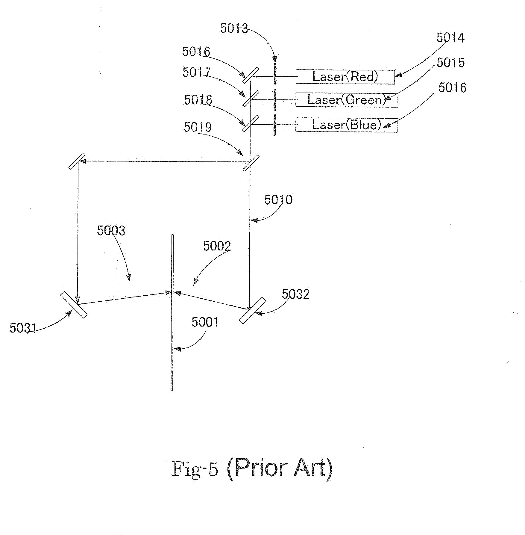
[0005] It is possible to adjust the angles of beams by location with step-by-step exposure system as shown in FIG. 4 (transmissive) and FIG. 5 (reflective). These systems incorporate Galvano mirrors (4005 and 4014) whose angle can be controlled electronically. These systems require adjustment of exposure locations because changing the angles of Galvano mirrors affect the location of exposure.
[0006] FIG. 6 and FIG. 7 do not require the adjustment, because regardless of the angles of Galvano mirrors, the location of exposure is fixed using F-.theta. lenses (FIG. 6) or Elliptic mirror (FIG. 7). However, these systems leave the non-uniformity at the border areas between two sub-arrays. Streaks between sub-arrays are often visible. Therefore, these methods have a major drawback of non-uniformity of exposure at the gaps between stepped exposures which affects image quality badly.
[0007] To obtain high quality uniform images requires non stepping exposure system which enables arbitrary adjustment of diffraction angles seamlessly. This invention provides seamless exposure with frill freedom of arbitrary diffraction angles.
[0008] FIG. 13 shows a typical example of diffractive optical element (DOE) which is usually opaque and periodic structure is only on the surface. These are made by lithographic process using semiconductor think film processes. Hologram can be much thicker than this type of DOE and the performances of thick hologram such as angular selectivity and wavelength selectivity are substantially better than those of thin DOE. However the instability of photopolymer such as shrinkage and deformation after recording is significant and the weakness against UV is also a major drawback of photopolymer. There is a significant need for stable and highly reliable hologram under high temperature and this invention provides a structure and manufacturing methods satisfying the need.
SUMMARY OF THE INVENTION
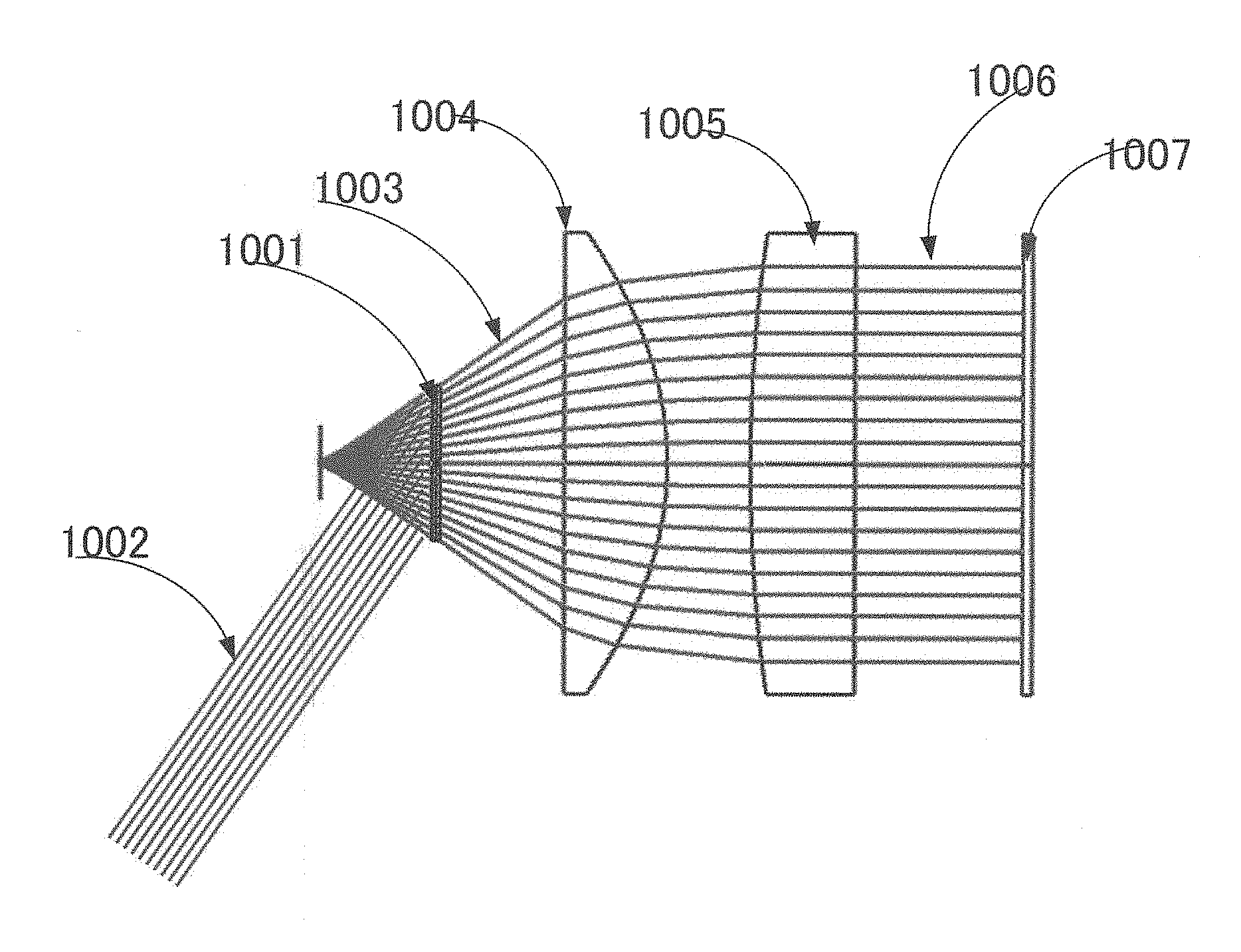
[0009] One of the objectives of this invention is to provide a seamless structure with arbitrary diffraction angle using a Free-Form-Lens or Free-Form-Lenses to record hologram in photopolymer. An example of embodiment is shown in FIG. 10. A photopolymer plate is located at (1001) and exposed with the recording beams (1002 and 1003), wherein a free-form lens is at (1005) and a spherical or aspherical lens (1004) is added to reduce the burden of the free-form-lens. The surface of free-form lens is designed to achieve desired angles of the stripes of hologram. Due to the evolution of recent technologies, the surface of free-form lens can be controlled in sub-microns and even in nano meter.
[0010] An example of reflective HOE is shown in FIG. 10, wherein 1001 is a photopolymer plate, 1002 is a collimated light beam and 1003 is a beam adjusted by a free-form lens(1005) and a aspherical lens (1005).
[0011] Another example of this invention is shown in FIG. 11 for a transmissive HOE(hologram), wherein 1107 is a photopolymer plate, 1105 is a collimated beam as a refence beam and 1104 is an object beam which is adjusted by a free-form lens (1102) and an aspherical lens (1103), so that the object beam is in the desired direction.
[0012] Another example of this invention is to use a half-mirror (1207) or PBS (polarized beam splitter), when there is not enough space between a hologram (1205) and a lens (1203).
[0013] FIG. 14 shows an example of this invention which enables thick hologram made of inorganic materials, which are substantially more stable and more reliable against high temperature and UV. 1401 is in first transparent inorganic material such as glass or other oxides. 1402 is a second transparent inorganic material with higher refractive index such as nitrides. Because both the materials are transparent, the majority of incident light which does not meet Braggs's condition will pass through the hologram except the light beams which meet the condition, but not the majority. This type of hologram is very suitable for see-through display such as Head-up-Displays and wearable displays.
BRIEF DESCRIPTION OF THE DRAWINGS
[0014] FIG. 1 illustrates the processes to form a hologram by applying two coherent beams superimposed on a photopolymer wherein the distribution of the light intensity of two interfered beams creates periodic stripes in a certain direction and in a certain pitch. The refractive index or photopolymer varies depending on the intensity or more particularly proportional to the intensity. The varied refractive index be fixed permanently with a chemical process. This process is called as "Recoding" of hologram.
[0015] FIG. 2 illustrates how an incident beam that is diffracted by the recorded hologram structure and the incident beam enters the hologram wherein there are high refractive index areas and low refractive index areas and the beam will be reflected by the stripes as if the stripes are mirrors, if the angle and wavelength of the incident beam and the pitch of stripes meet so called Bragg's law. Unless otherwise, the incident light beam passes through.
[0016] FIG. 3 illustrates a conventional process, wherein a transmissive hologram with a mask pattern so that an image shows up (playback) when an illumination (marked B) light beam is provided.
[0017] FIG. 4 illustrates an example of recording a transmissive hologram using a step-by-step exposure, wherein 4004 and 4014 are Galvano mirrors to adjust the angle of incident beams. This system allows the adjustment of angle of incident beams arbitrarily, the landing location of beam varies with the mirror angle and requires an adjustment every exposure.
[0018] FIG. 5 illustrates an example of recording a reflective hologram using a step-by-step exposure, wherein 5031 and 5032 are Galvano mirrors to adjust the angle of incident beams. This system allows the adjustment of angle of incident beams arbitrarily, the landing location of beam varies with the mirror angle and requires an adjustment every exposure.
[0019] FIG. 6 is an example of recording a reflective type of hologram using F.theta. lenses (6002 and 6003), so that the system does not require any adjustment of exposure location, because regardless of the angles of Galvano mirrors (6005 and 6035), the location of exposure is fixed using F-.theta. lenses
[0020] FIG. 7 is an example of recording a reflective type of hologram using an elliptic mirror (7023), wherein the light starting from one of foci is always reflected toward the second focus, so that the system does not require any adjustment of exposure location, because regardless of the angles of Galvano mirrors (6005 and 6035), the location of exposure is fixed to the second focus.
[0021] FIG. 8 illustrates an example of recording, a transmissive hologram using step-by-step exposure. In case of transmissive recording, two recording light sources often interfere due to the narrow space between a lens and a hologram plate (5004).
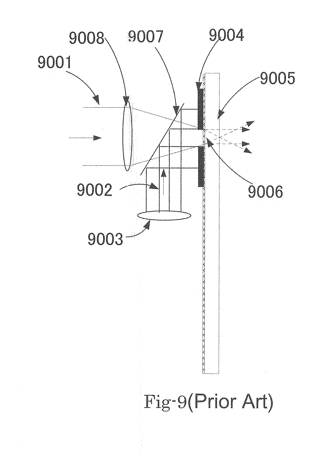
[0022] FIG. 9 illustrates an example of to avoid the interference of tools, a beam splitter (9007) is used. For the beam splitter, half-mirror or a PBS (polarized beam splitter) can be used. Even overcoming these difficulties, there is residual non-uniformity of exposure remains.
[0023] FIG. 10 is a system to record a reflective type of hologram.
[0024] FIG. 11 is a system to record a transmissive type of hologram,
[0025] FIG. 12 is a system to record a transmissive type a hologram with a beam splitter.
[0026] FIG. 13 shows an example of conventional DOE (diffractive optical element).
[0027] FIG. 14 shows an example of thick hologram made of inorganic material,
DETAIL DESCRIPTIONS OF THE PREFERRED EMBODIMENTS
[0028] FIG. 10 is an example of this invention to record a reflective type of hologram, wherein 1002 is a collimated light beam and a coherent light beam (1006) is lead to a free-form-lens (1005) and an aspherical lens (1004) so that the direction and the location of recording light beam (1003) is adjusted to meet the required diffraction angle at each location of hologram (1001). This system does not have non-uniformity due to stepping, because the entire area is exposed simultaneously without any division. This system provides completely arbitrary adjustment of diffraction angle
[0029] FIG. 11 is an example of this invention to record a transmissive type of hologram, wherein 1105 is a collimated light beam and a coherent light beam (1101) is lead to a free-form-lens (1102) and an aspherical lens (1103) so the direction and the location of recording light beam (1104) is adjusted to meet the required diffraction angle at each location of hologram (1107). This system does not have non-uniformity due to stepping, because the entire area is exposed simultaneously without any division. This system provides completely arbitrary adjustment of diffraction angle and seamless exposure.
[0030] FIG. 12 is an example of this invention to record a transmissive type of hologram when the spare between the lens system and hologram is not sufficient, wherein (1206) is a collimated light beam and is reflected by a beam splitter (1207) toward a hologram(1205) and a coherent light beam (1201) is lead to a free-form-lens (1202) and an aspherical lens (1203) so that the direction and the location of recording light beam (1204) is adjusted to meet the required diffraction angle at each location of hologram (120). This system does not have non-uniformity due to stepping, because the entire area is exposed simultaneously without any division. This system provides completely arbitrary adjustment of diffraction angle and seamless exposure.
[0031] FIG. 13 shows an example of DOE (diffractive optical element). On a substrate (1302), blazed structure (1301) is created either by machining or lithographical method as shown in (FIG. 13). A DOE made of inorganic material can be produced much more precisely and reliably than hologram made of organic photopolymer which deforms during recording and chemical processes. However due to its thin structure (often submicron), the performance is often limited compared with hologram which can be made thicker than DOE.
[0032] FIG. 14 shows an example of this invention of thick hologram made of inorganic material. Using lithography and deposition tools, thicker hologram can be made of inorganic material such as dielectric material including oxide and nitride. 140 is a transparent inorganic dielectric material stich as glass and 1402 is another transparent inorganic material with higher refractive index than that of 1401. With a multi-layer structure using lithography, deposition and etching, the tilt angle shown as 1406 and the pitch between stripes (1405) can be controlled precisely and arbitrarily.
[0033] The foregoing description, for purpose of explanation, has been described with reference to specific embodiments. However, the illustrative discussions above are not intended to be exhaustive or to limit the disclosure to the precise forms disclosed. Many modifications and variations are possible in view of the above teachings. The embodiments were chosen and described in order to best explain the principles of the disclosure and its practical applications, to thereby enable others skilled in the art to best utilize the disclosure and various embodiments with various modifications as ate suited to the particular use contemplated.
* * * * *
D00000
D00001
D00002
D00003
D00004
D00005
D00006
D00007
D00008
D00009
D00010
D00011
D00012

D00013

D00014

XML
uspto.report is an independent third-party trademark research tool that is not affiliated, endorsed, or sponsored by the United States Patent and Trademark Office (USPTO) or any other governmental organization. The information provided by uspto.report is based on publicly available data at the time of writing and is intended for informational purposes only.
While we strive to provide accurate and up-to-date information, we do not guarantee the accuracy, completeness, reliability, or suitability of the information displayed on this site. The use of this site is at your own risk. Any reliance you place on such information is therefore strictly at your own risk.
All official trademark data, including owner information, should be verified by visiting the official USPTO website at www.uspto.gov. This site is not intended to replace professional legal advice and should not be used as a substitute for consulting with a legal professional who is knowledgeable about trademark law.