Expandable Light Guide For Backlight
Dunn; William
U.S. patent application number 16/259921 was filed with the patent office on 2019-05-23 for expandable light guide for backlight. The applicant listed for this patent is Manufacturing Resources International, Inc.. Invention is credited to William Dunn.
| Application Number | 20190154909 16/259921 |
| Document ID | / |
| Family ID | 53265168 |
| Filed Date | 2019-05-23 |


| United States Patent Application | 20190154909 |
| Kind Code | A1 |
| Dunn; William | May 23, 2019 |
EXPANDABLE LIGHT GUIDE FOR BACKLIGHT
Abstract
Described herein are exemplary embodiments of a light guide assembly for a backlight and backlight assemblies using such light guide assemblies. An exemplary backlight assembly may have a light guide with a pair of opposing edges and a sliding LED subassembly placed along an edge of the light guide and attached to the light guide so that movement of the light guide causes movement of the sliding LED subassembly. In some embodiments, a first slot may be positioned within the light guide where a post extends from the sliding LED subassembly to engage with the first slot in the light guide. In some embodiments, a back pan may be positioned behind the light guide where a post can extend from the back pan to engage with a second slot in the light guide.
| Inventors: | Dunn; William; (Alpharetta, GA) | ||||||||||
| Applicant: |
|
||||||||||
|---|---|---|---|---|---|---|---|---|---|---|---|
| Family ID: | 53265168 | ||||||||||
| Appl. No.: | 16/259921 | ||||||||||
| Filed: | January 28, 2019 |
Related U.S. Patent Documents
| Application Number | Filing Date | Patent Number | ||
|---|---|---|---|---|
| 14558326 | Dec 2, 2014 | 10191212 | ||
| 16259921 | ||||
| 61910568 | Dec 2, 2013 | |||
| Current U.S. Class: | 1/1 |
| Current CPC Class: | G02F 1/133615 20130101; G02B 6/0091 20130101 |
| International Class: | F21V 8/00 20060101 F21V008/00 |
Claims
1. A light guide assembly for a backlight, comprising: a light guide having an edge to be illuminated; at least one slot in the light guide, the slot having a length that extends parallel to the edge of the light guide; a connecting assembly coupled to the light guide, the connecting assembly having a light guide connecting portion and a LED mounting portion that resides adjacent to and parallel with the edge of the light guide when the connecting assembly is coupled thereto; and a light guide spacer interposed between the light guide and the light guide connecting portion of the connecting assembly; whereby the connecting assembly is constrained to move in kind with the light guide during thermal expansion or contraction of the light guide in a direction perpendicular to the length of the at least one slot in the light guide.
2. The light guide assembly of claim 1, wherein the light guide is freely movable relative to the connecting assembly in a direction parallel to the length of the at least one slot in the light guide.
3. The light guide assembly of claim 1, wherein the light guide spacer couples the connecting assembly to the light guide.
4. The light guide assembly of claim 1, wherein: the light guide spacer is coupled to the light guide connecting portion of the connecting assembly; and the light guide spacer further includes a coupling element that extends therefrom into the at least one slot in the light guide.
5. The light guide assembly of claim 1, wherein the light guide spacer and the connecting assembly are connected by posts.
6. The light guide assembly of claim 1, wherein the connecting assembly is substantially L-shaped, the light guide connecting portion resides rearward of the light guide, and the LED mounting portion extends transversely from the light guide connecting portion.
7. The light guide assembly of claim 6, wherein the LED mounting portion of the connecting assembly resides at a predetermined, fixed distance from the edge of the light guide.
8. The light guide assembly of claim 1, further comprising a back pan residing rearward of the light guide spacer.
9. A light guide assembly for a backlight, comprising: a planar light guide having first and second opposing edges to be illuminated; a plurality of slots in the light guide, each slot having a length that extends parallel to the first and second opposing edges of the light guide; first and second planar light guide spacers residing rearward of the light guide and respectively associated with the first and second opposing edges of the light guide; and first and second L-shaped LED connecting assemblies, each LED connecting assembly having a connecting portion that resides rearward of the light guide and is coupled to a respective one of the light guide spacers and to the light guide, and a LED mounting portion that extends transversely from the light guide connecting portion to reside adjacent to and parallel with a respective one of the opposing edges of the light guide when the connecting assemblies are coupled thereto; whereby the light guide spacers and the connecting assemblies are constrained to move in kind with the light guide during thermal expansion or contraction of the light guide in a direction perpendicular to the length of the slots in the light guide.
10. The light guide assembly of claim 9, wherein the light guide is freely movable relative to the connecting assembly in a direction parallel to the length of the at least one slot in the light guide.
11. The light guide assembly of claim 9, wherein: each light guide spacer is coupled to the connecting portion of its respective LED connecting assembly by at least one post; and each light guide spacer further includes a plurality of coupling elements that extend therefrom into corresponding ones of the slots in the light guide.
12. The light guide assembly of claim 9, wherein the LED mounting portions of the first and second LED connecting assemblies reside at a predetermined, fixed distance from the respective first and second opposing edges edge of the light guide.
13. The light guide assembly of claim 9, further comprising a back pan residing rearward of the light guide spacer.
14. The light guide assembly of claim 13, further comprising a plurality of slots through the back pan, the slots having a length that extends perpendicular to the slots in the light guide and arranged to receive a portion of the posts coupling the light guide spacers to the connecting portion of the LED connecting assemblies.
15. A backlight assembly, comprising: a light guide having first and second opposing edges to be illuminated; a plurality of slots in the light guide, each slot having a length that extends parallel to the first and second opposing edges of the light guide; and first and second sliding LED subassemblies coupled to the light guide via the plurality of slots therein, each sliding LED subassembly including a set of LEDs that are positioned in parallel with and at a fixed distance from a respective one of the opposing edges of the light guide; wherein the sliding LED subassemblies are constrained to move in kind with the light guide during thermal expansion or contraction of the light guide in a direction perpendicular to the length of the slots in the light guide, such that the fixed distance between the sets of LEDs and the respective edges of the light guide remains constant.
16. The backlight assembly of claim 15, wherein each sliding LED subassembly includes: a L-shaped LED connecting assembly having a connecting portion that resides rearward of the light guide and a LED mounting portion that extends transversely from the light guide connecting portion to reside adjacent to and parallel with a respective one of the opposing edges of the light guide when the connecting assemblies are coupled thereto; and a light guide spacer interposed between the light guide and the connecting portion of the LED connecting assembly.
17. The backlight assembly of claim 16, wherein the light guide spacers serve to couple the sliding LED subassemblies to the light guide.
18. The backlight assembly of claim 17, wherein: the light guide spacers are coupled to the sliding LED subassemblies by posts; and each light guide spacer includes a plurality of coupling elements that extend therefrom into corresponding ones of the slots in the light guide
19. The backlight assembly of claim 16, further comprising a back pan located rearward of the light guide spacers.
20. The backlight assembly of claim 15, wherein each set of LEDs is mounted to the LED mounting portion of its respective LED connecting assembly with a substrate therebetween.
Description
CROSS-REFERENCE TO RELATED APPLICATIONS
[0001] This application is a continuation of U.S. patent application Ser. No. 14/558,326 filed on Dec. 2, 2014, which claims the benefit of U.S. Provisional Application No. 61/910,568 filed on Dec. 2, 2013, each of which are herein incorporated by reference in their entirety.
TECHNICAL FIELD
[0002] Embodiments described herein generally relate to light guides that are configured to account for thermal expansion/contraction and backlight assemblies utilizing such light guides.
BACKGROUND OF THE ART
[0003] Backlit displays are used in a number of applications including advertising, entertainment, or informational applications. They are also used in a number of different operating environments including outdoors, direct sunlight, or other applications which may have warm or cool ambient temperatures surrounding the display. Most backlights utilize some form of light guide, which is commonly made of materials which may be affected by changes in temperature. Thermal expansion or contraction of the light guide can cause both mechanical and optical defects in the display.
SUMMARY OF THE EXEMPLARY EMBODIMENTS
[0004] Exemplary embodiments provide a backlight assembly where the light guide is permitted to expand and contract without substantially changing the distance between the LEDs and the light guide. A first set of slots may be placed in the light guide and a second set of slots are preferably positioned on the opposite side of the light guide and parallel to the first set of slots. The first set of slots may engage with a post which extends from the back pan. The second set of slots may contain a post which extends from a sliding LED subassembly. The sliding LED subassembly is preferably connected with the light guide so that the LEDs within the subassembly can move with the light guide.
[0005] The foregoing and other features and advantages of the present invention will be apparent from the following more detailed description of the particular embodiments, as illustrated in the accompanying drawings.
BRIEF DESCRIPTION OF THE DRAWINGS
[0006] A better understanding of an exemplary embodiment will be obtained from a reading of the following detailed description and the accompanying drawings wherein identical reference characters refer to identical parts and in which:
[0007] FIG. 1 is a front perspective view of a backlit display.
[0008] FIG. 2 is an exploded view of an edge-lit backlight assembly.
[0009] FIG. 3 is a side planar view of the edge-lit backlight assembly shown in FIG. 2 where the advertising poster or LCD stack has been removed.
[0010] FIG. 4 is a front planar view of the relative positioning of the LEDs in relation to the light guide.
[0011] FIG. 5 is a front perspective view of an exemplary backlight assembly where the advertising poster or LCD stack has been removed.
[0012] FIG. 6 is a front perspective view of the left top corner of the backlight assembly shown in FIG. 5 where the top bezel has been removed.
[0013] FIG. 7 is a front perspective view of the left bottom corner of the backlight assembly shown in FIG. 5 where the bottom bezel has been removed.
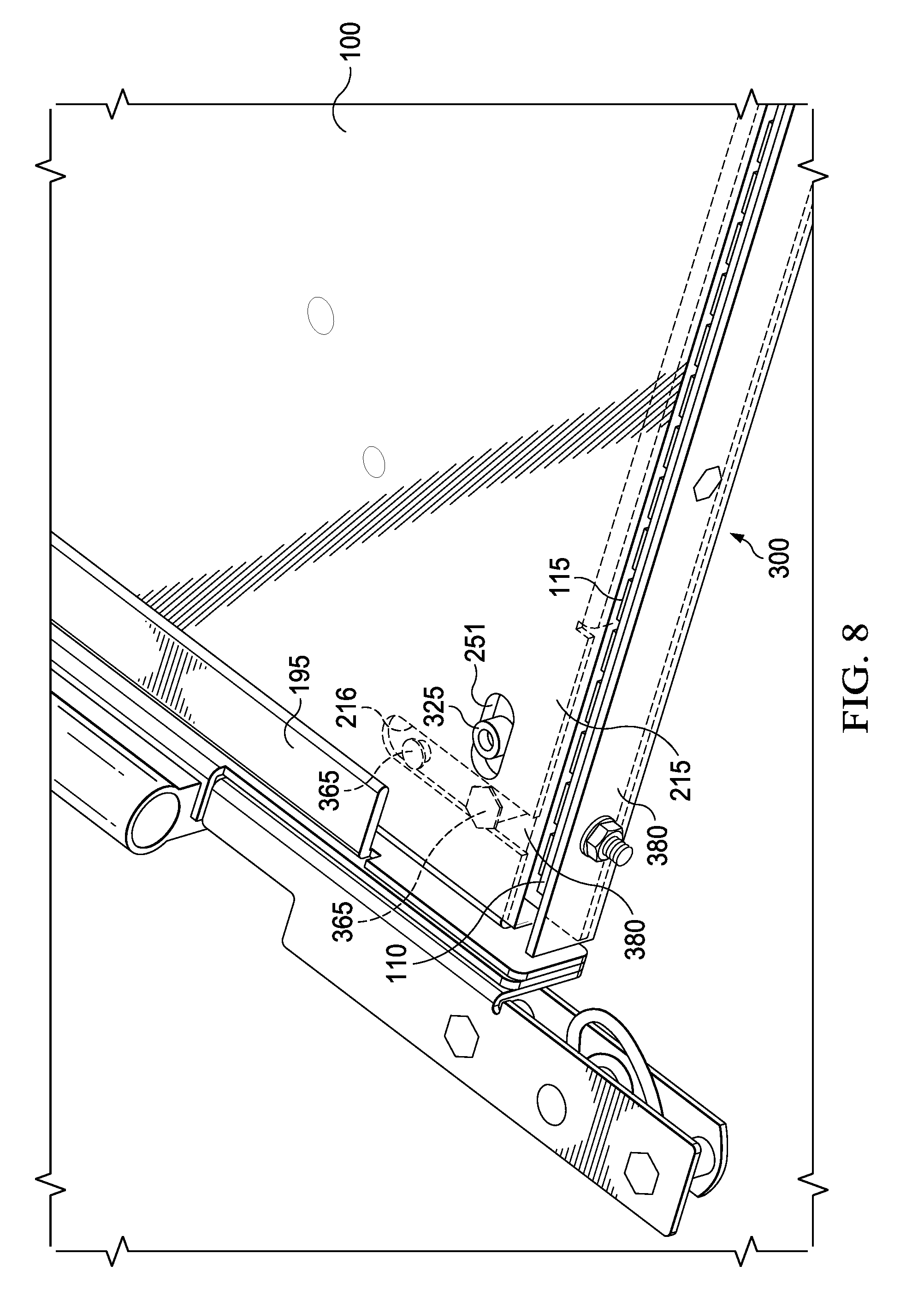
[0014] FIG. 8 is the same view as FIG. 7 where the light guide spacer has been removed.
[0015] FIG. 9 is a front perspective view of the bottom edge of the backlight assembly shown in FIG. 5 where the bottom bezel and light guide spacer have been removed.
[0016] FIG. 10 is a rear perspective view of the left bottom edge of the backlight assembly shown in FIG. 5.
DETAILED DESCRIPTION OF THE EXEMPLARY EMBODIMENTS
[0017] The invention is described more fully hereinafter with reference to the accompanying drawings, in which exemplary embodiments of the invention are shown. This invention may, however, be embodied in many different forms and should not be construed as limited to the exemplary embodiments set forth herein. Rather, these embodiments are provided so that this disclosure will be thorough and complete, and will fully convey the scope of the invention to those skilled in the art. In the drawings, the size and relative sizes of layers and regions may be exaggerated for clarity.
[0018] The terminology used herein is for the purpose of describing particular embodiments only and is not intended to be limiting of the invention. As used herein, the singular forms "a", "an" and "the" are intended to include the plural forms as well, unless the context clearly indicates otherwise. It will be further understood that the terms "comprises" and/or "comprising," when used in this specification, specify the presence of stated features, integers, steps, operations, elements, and/or components, but do not preclude the presence or addition of one or more other features, integers, steps, operations, elements, components, and/or groups thereof.
[0019] Embodiments of the invention are described herein with reference to illustrations that are schematic illustrations of idealized embodiments (and intermediate structures) of the invention. As such, variations from the shapes of the illustrations as a result, for example, of manufacturing techniques and/or tolerances, are to be expected. Thus, embodiments of the invention should not be construed as limited to the particular shapes of regions illustrated herein but are to include deviations in shapes that result, for example, from manufacturing.
[0020] Unless otherwise defined, all terms (including technical and scientific terms) used herein have the same meaning as commonly understood by one of ordinary skill in the art to which this invention belongs. It will be further understood that terms, such as those defined in commonly used dictionaries, should be interpreted as having a meaning that is consistent with their meaning in the context of the relevant art and will not be interpreted in an idealized or overly formal sense unless expressly so defined herein.
[0021] FIG. 1 is a front perspective view of a backlit display. Here, the backlight and graphic/LCD stack are preferably contained within a housing 10 with a protective transparent sheet 15 placed in front of the graphic/LCD stack. In some embodiments, the protective transparent sheet 15 is glass and may be two sheets of glass laminated together using optical adhesive.
[0022] FIG. 2 is an exploded view of an edge-lit backlight assembly. FIG. 3 is a side planar view of the edge-lit backlight assembly shown in FIG. 2 where the advertising poster or LCD stack has been removed.
[0023] Here, a lamp and reflector assembly is positioned along the edge of a light guide plate (LGP) such that the light emitted from the lamp and reflector assembly is directed into the LGP. A reflection sheet is preferably placed behind the LGP so that light rays can go through a series of reflections and refractions until exiting the front surface of the LGP and illuminating the advertising poster or LCD stack. Generally, a pair of lamp and reflector assemblies are positioned on opposing edges of the LGP.
[0024] As used herein, the term `LCD stack` is defined as any LCD assembly capable of generating an image from backlight illumination. The term `LCD stack` includes any type of LCD design, including but not limited to twisted nematic, in-plane switching, super in-plane switching, TFT dual transistor, fringe field switching and advanced fringe field switching, vertical alignment, advanced super view, and blue phase mode. The various layers and orientation of the layers will vary depending on the particular type of LCD stack and the exemplary embodiments described herein do not require anything specific from the LCD stack other than generating an image.
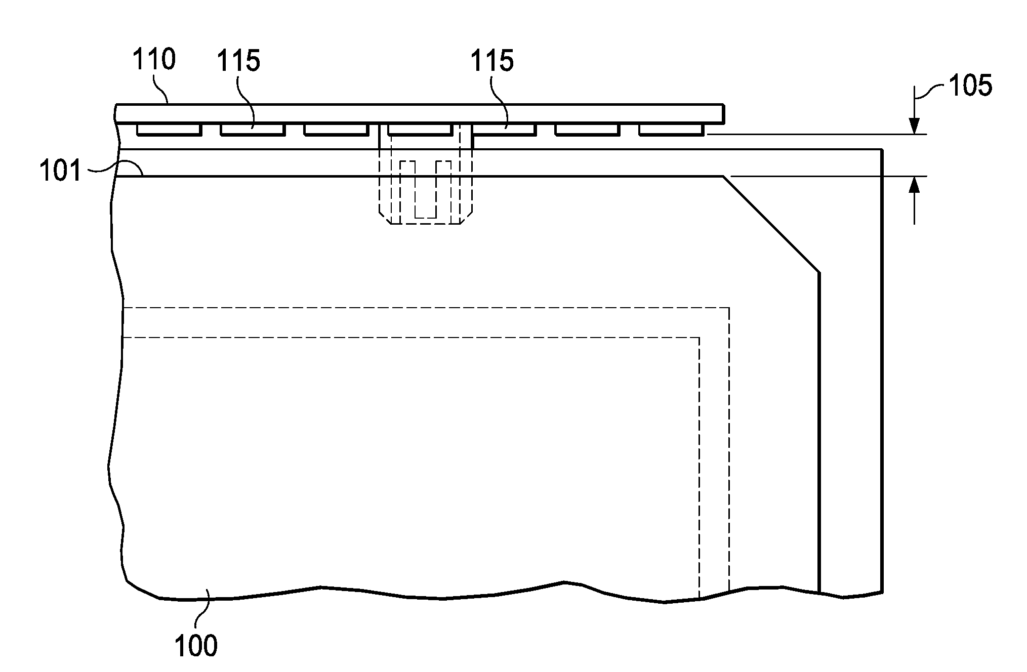
[0025] FIG. 4 is a front planar view of the relative positioning of the LEDs 115 in relation to the light guide 100. The LEDs 115 are preferably mounted to a substrate 110 which is typically some type of printed circuit board (PCB), preferably a metal core PCB. The substrate 110 is preferably positioned so as to produce the desired distance (D) 105 between the edge 101 of the light guide 100 and the LEDs 115. The distance (D) 105 may be selected based on the effectiveness and efficiency of the resulting illumination exiting the front surface of the light guide 100. It is desirable to then maintain this distance (D) 105 even though thermal expansion/contraction of the light guide 100 throughout its lifetime.
[0026] FIG. 5 is a front perspective view of an exemplary backlight assembly where the assembly has been removed from the housing 10 and the front protective transparent plate 15 as well as the advertising poster or LCD stack has been removed. The light guide 100 may be surrounded by a top bezel 180 along the top edge 200, bottom bezel 190 along the bottom edge 300, and side bezels 195 along the sides of the backlight assembly. In this embodiment, the LED assemblies are positioned along the top edge 180 and bottom edge 300, but it should be noted that this is not required. In other embodiments the LED assemblies could be positioned along the opposing side vertical edges of the assembly or only along one edge of the assembly, be it top 200, bottom 300, or sides. It should also be noted, that although shown with a `portrait` orientation (where the backlight has a longer vertical dimension than the horizontal dimension) this is not required as the backlight could also be square or could be in the `landscape` orientation (where the backlight has a longer horizontal dimension than the vertical dimension).
[0027] FIG. 6 is a front perspective view of the left top corner of the backlight assembly shown in FIG. 5 where the top bezel 180 has been removed. A back pan 215 is preferably fixed within the housing 10 and contains a post 225 which extends forward (towards an intended observer) from the back pan 215 and passes through a slot 250 which is placed within the light guide 100. In this particular embodiment, the distance 105 is provided as the distance between the top edge 101 of the light guide 100 and the LEDs 115. Here, the slot 250 is preferably oriented perpendicular to the distance 105 such that the light guide 100 is fixed within the vertical dimension but is free to move in the horizontal dimension. Some embodiments may use more than one slot 250 in the light guide, with some distributing a plurality of slots across the top edge of the light guide 100.
[0028] It should also be noted that some embodiments may utilize clamps rather than the slots shown in the embodiments herein. Thus, a plurality of clamps may be used to hold each LED subassembly at the desired distance from the edge of the light guide, while permitting the light guide itself to move freely within the enclosure. Further, other embodiments may use tabs to hang the light guide vertically while permitting it to expand and contract.
[0029] FIG. 7 is a front perspective view of the left bottom corner of the backlight assembly shown in FIG. 5 where the bottom bezel 190 has been removed. Preferably, another slot 251 is placed within the light guide 100, with this slot 251 being placed near the bottom edge of the light guide 100 and is substantially parallel to the slot 250 which is positioned at the top of the light guide 100. A light guide spacer 350 is preferably positioned behind the light guide 100 and contains a post 325 which extends from the light guide spacer 350 forwards (towards an intended observer) and passing through the slot 251. In this way, the light guide 100 can expand/contract in the horizontal dimension without having much effect on the light guide spacer 350. However, when the light guide 100 expands/contracts vertically, through the post 325 it will cause the light guide spacer 350 to move as well.
[0030] A connecting assembly 380 is preferably attached to the light guide spacer 350 so that the connecting assembly 380 will move when the light guide spacer 350 moves. The connecting assembly 380 is then preferably connected to another substrate 110 containing a plurality of LEDs 115. In this way, the substrate 110 and LEDs 115 preferably move when the connecting assembly 380 moves. Generally speaking, the light guide spacer 350, connecting assembly 380, substrate 110, and LEDs 115 may be collectively referred to as a sliding LED subassembly, indicated generally as 400. However, it should be noted that other pieces may be included in the sliding LED subassembly 400, and in some embodiments the light guide spacer 350 and connecting assembly 380 may comprise a single piece. In a preferred embodiment, the collective parts of the sliding LED subassembly 400 preferably move together as a unit. As shown and described in this embodiment, the sliding LED subassembly 400 is permitted to move vertically but is constrained from substantially horizontal movement.
[0031] A substrate 110 containing a plurality of LEDs 115 is preferably placed adjacent to the bottom edge of the light guide 100 and again is preferably placed to obtain the desired distance 105 from the edge of the light guide 100 to the LEDs 115 on the substrate 110. The slot 251 is again preferably positioned perpendicular to the distance 105. In this embodiment, a pair of posts 365 are used to connect the light guide spacer 350 with the connecting assembly 380, although posts are not required nor is it required that a pair of them are used. Any technique for attaching the light guide spacer 350 to the connecting subassembly 380 would be acceptable (rivets, fasteners, adhesive, welding, etc.) and some embodiments may provide the light guide spacer 350 and connecting assembly 380 as a single unitary piece.
[0032] FIG. 8 is the same view as FIG. 7 where the light guide spacer 350 has been removed. The back pan 215 is preferably behind the light guide spacer and may contain a slot 216 to allow the posts 365 (which pass through the slot 216 to connect the light guide spacer 350 with the connecting assembly 380) to slide in a direction perpendicular to the direction of the slot 251 within the light guide 100. Since the substrate 110 containing the LEDs 115 is preferably attached to the connecting assembly 380, the LEDs 115 will move with the connecting assembly 380 which moves with the light guide spacer 350, which moves with the light guide 100 due to the post 325. Therefore, the substrate 110 and LEDs 115 will travel with the light guide 100 as it expands and contracts, thus maintaining the desired distance 105 between the light guide 100 and the LEDs 115.
[0033] FIG. 9 is a front perspective view of the bottom edge of the backlight assembly shown in FIG. 5 where the bottom bezel 190 and light guide spacer 350 have been removed. Here, a plurality of slots 216 are distributed across the bottom edge 300 of the backlight assembly, or in this embodiment, across the bottom edge of the back pan 215.
[0034] FIG. 10 is a rear perspective view of the left bottom edge of the backlight assembly shown in FIG. 5. The posts 365 are shown connecting the light guide spacer 350 with the connecting assembly 380. As indicated, the sliding LED subassembly 400 (including the substrate 110 and LEDs 115) is permitted to travel back and forth to match the movement of the light guide 100.
[0035] Having shown and described a preferred embodiment of the invention, those skilled in the art will realize that many variations and modifications may be made to affect the described invention and still be within the scope of the claimed invention. Additionally, many of the elements indicated above may be altered or replaced by different elements which will provide the same result and fall within the spirit of the claimed invention. It is the intention, therefore, to limit the invention only as indicated by the scope of the claims.
* * * * *
D00000
D00001
D00002
D00003
D00004
D00005
D00006
D00007
D00008
D00009
D00010
XML
uspto.report is an independent third-party trademark research tool that is not affiliated, endorsed, or sponsored by the United States Patent and Trademark Office (USPTO) or any other governmental organization. The information provided by uspto.report is based on publicly available data at the time of writing and is intended for informational purposes only.
While we strive to provide accurate and up-to-date information, we do not guarantee the accuracy, completeness, reliability, or suitability of the information displayed on this site. The use of this site is at your own risk. Any reliance you place on such information is therefore strictly at your own risk.
All official trademark data, including owner information, should be verified by visiting the official USPTO website at www.uspto.gov. This site is not intended to replace professional legal advice and should not be used as a substitute for consulting with a legal professional who is knowledgeable about trademark law.