Firearm Projectiles With Turbulence-inducing Surfaces, Firearm Cartridges Including The Same, And Associated Methods
Amick; Darryl D.
U.S. patent application number 16/196965 was filed with the patent office on 2019-05-23 for firearm projectiles with turbulence-inducing surfaces, firearm cartridges including the same, and associated methods. The applicant listed for this patent is Amick Family Revocable Living Trust. Invention is credited to Darryl D. Amick.
| Application Number | 20190154421 16/196965 |
| Document ID | / |
| Family ID | 66532257 |
| Filed Date | 2019-05-23 |


| United States Patent Application | 20190154421 |
| Kind Code | A1 |
| Amick; Darryl D. | May 23, 2019 |
FIREARM PROJECTILES WITH TURBULENCE-INDUCING SURFACES, FIREARM CARTRIDGES INCLUDING THE SAME, AND ASSOCIATED METHODS
Abstract
Firearm projectiles with turbulence-inducing surfaces, firearm cartridges including the same, and associated methods. A firearm projectile comprises a projectile body and a turbulence-inducing surface at least substantially enclosing the projectile body. The firearm projectile is at least substantially spherical. The turbulence-inducing surface is configured to induce a drag crisis in a drag coefficient of the firearm projectile when the firearm projectile travels through air with a Reynolds number that is less than 300,000.
| Inventors: | Amick; Darryl D.; (Albany, OR) | ||||||||||
| Applicant: |
|
||||||||||
|---|---|---|---|---|---|---|---|---|---|---|---|
| Family ID: | 66532257 | ||||||||||
| Appl. No.: | 16/196965 | ||||||||||
| Filed: | November 20, 2018 |
Related U.S. Patent Documents
| Application Number | Filing Date | Patent Number | ||
|---|---|---|---|---|
| 62707888 | Nov 21, 2017 | |||
| Current U.S. Class: | 1/1 |
| Current CPC Class: | F42B 7/046 20130101; F42B 10/38 20130101 |
| International Class: | F42B 10/38 20060101 F42B010/38; F42B 7/04 20060101 F42B007/04 |
Claims
1. (canceled)
2. The shot shell of claim 12, wherein when a shot pellet of the plurality of shot pellets traveling through air has a Reynolds number that is less than 300,000, the shot pellet has a drag coefficient that is less than 0.35.
3. The shot shell of claim 12, wherein each shot pellet of the plurality of shot pellets has a drag coefficient when traveling through air at a given velocity that is at most 0.7 times a drag coefficient of a smooth spherical projectile of the same mass and material composition as the shot pellet and that lacks the turbulence-inducing surface when the smooth spherical projectile travels through air with the given velocity.
4. The shot shell of claim 12, wherein the turbulence-inducing surface of each of the plurality of shot pellets is integral with the respective projectile body of each of the plurality of shot pellets.
5. The shot shell of claim 12, wherein the turbulence-inducing surface of each of the plurality of shot pellets consists of a plurality of non-overlapping surface loci; wherein each surface locus of the plurality of surface loci has a corresponding locus radius, as measured between the surface locus and a center point of the projectile body; wherein each shot pellet of the plurality of shot pellets has a reference radius that is equal to the arithmetic mean of the corresponding locus radii of the plurality of surface loci; wherein each surface locus of the plurality of surface loci further has a corresponding radial deviation that is equal to the corresponding locus radius minus the reference radius; wherein each shot pellet of the plurality of shot pellets is characterized by a roughness metric that is based, at least in part, on the set of corresponding radial deviations of the plurality of surface loci; wherein the roughness metric includes a relative roughness ratio, defined as the ratio of a characteristic roughness depth of the turbulence-inducing surface to a diameter of the shot pellet; wherein the characteristic roughness depth is equal to an arithmetical mean deviation, defined as the arithmetic mean of the absolute values of the set of corresponding radial deviations of the plurality of surface loci; and wherein the absolute value of the relative roughness ratio is at least 0.0001 and at most 0.035.
6. The shot shell of claim 5, wherein the plurality of surface loci includes at least 10,000 surface loci.
7. The shot shell of claim 12, wherein the turbulence-inducing surface of each shot pellet of the plurality of shot pellets includes a plurality of localized surface features, wherein each localized surface feature includes at least one of a depression, an indentation, and a crater.
8. The shot shell of claim 7, wherein at least one localized surface feature includes a depression that is at least substantially surrounded by a raised rim.
9. The shot shell of claim 12, wherein the turbulence-inducing surface of each shot pellet of the plurality of shot pellets includes a plurality of elongate surface features, wherein each elongate surface feature includes at least one of a ridge, an edge, a channel, a groove, and a scratch.
10. The shot shell of claim 9, wherein the plurality of elongate surface features includes a plurality of scratches that are randomly oriented with respect to one another.
11. The shot shell of claim 9, wherein the plurality of elongate surface features include at least one of intersecting and partially overlapping surface features.
12. A shot shell, comprising: a casing that defines an internal volume; a propellant disposed in the internal volume; a primer disposed in the internal volume and configured to ignite the propellant; a wad disposed in the internal volume and separating the propellant and the primer from a payload region of the shot shell; and a plurality of shot pellets received within the payload region of the shot shell, each of the plurality of shot pellets is at least substantially spherical and comprises: a projectile body; and a turbulence-inducing surface at least substantially enclosing the projectile body; wherein the turbulence-inducing surface of each shot pellet of the plurality of shot pellets is configured to induce a drag crisis in a drag coefficient of the shot pellet when the shot pellet traveling through air has a Reynolds number that is less than 300,000.
13. (canceled)
14. The shot shell of claim 12, wherein the shot shell is configured to propel the plurality of shot pellets with a muzzle velocity that is at least 350 meters per second (1,148 feet per second).
15. A method of manufacturing each shot pellet of the plurality of shot pellets of claim 12, the method comprising: providing a base projectile that is at least substantially spherical, wherein the base projectile includes a smooth exterior surface; and forming the turbulence-inducing surface on the exterior surface of the base projectile.
16. The method of claim 15, wherein the providing the base projectile includes providing a projectile precursor that is not substantially spherical and shaping the projectile precursor into the base projectile that is at least substantially spherical.
17. The method of claim 15, wherein the forming the turbulence-inducing surface includes chemically etching the exterior surface of the base projectile with an acid.
18. The method of claim 15, wherein the forming the turbulence-inducing surface includes mechanically deforming the exterior surface of the base projectile.
19. The method of claim 18, wherein the mechanically deforming the exterior surface of the base projectile includes mechanically abrading the exterior surface of the base projectile via a shear process by rolling the base projectile relative to an abrasive belt.
20. The method of claim 18, wherein the mechanically deforming the exterior surface of the base projectile includes abrasively blasting the exterior surface of the base projectile with an abrasive medium that includes one or more of air, water, sand, grit, and pellets.
21. The shot shell of claim 12, wherein each shot pellet of the plurality of shot pellets has a diameter that is at least 2 millimeters (mm) and that is at most 10 mm.
22. The shot shell of claim 12, wherein each shot pellet of the plurality of shot pellets has a density that is at least 6.5 grams per cubic centimeter (g/cc).
23. The shot shell of claim 1, wherein the turbulence-inducing surface of each shot pellet of the plurality of shot pellets includes a plurality of at least partially overlapping depressions, indentations, and/or craters.
24. The shot shell of claim 12, wherein at least 95 wt % of each shot pellet of the plurality of shot pellets is metal.
Description
RELATED APPLICATION
[0001] The present application claims priority under 35 U.S.C. .sctn. 119(e) to U.S. Provisional Patent Application No. 62/707,888, which was filed on Nov. 21, 2017, the disclosure of which is hereby incorporated by reference.
FIELD
[0002] The present disclosure relates generally to the field of firearm ammunition.
BACKGROUND
[0003] Firearm projectiles generally are configured to travel through air at high velocities, such as velocities exceeding 400 meters per second (m/s). As a firearm projectile travels through air, drag forces act to reduce the velocity of the projectile such that the velocity of the projectile upon reaching a target is diminished significantly relative to the initial (muzzle) velocity of the projectile. Accordingly, firearm cartridges must include sufficient propellant to ensure that the firearm projectile retains sufficient velocity upon reaching its target. However, increasing the charge of propellant within a firearm cartridge also may serve to increase a material cost of the cartridge, and the correspondingly increased setback forces upon firing the cartridge may introduce excessive recoil felt by the shooter and/or unwanted wear to the firearm and/or projectile.
[0004] To optimize velocity retention during the flight of a firearm projectile, it generally is desirable to minimize the drag forces exerted upon the projectile during flight, such as by minimizing a drag coefficient of the projectile. While the drag coefficient of a given object generally depends on a variety of factors, it generally is believed that a perfectly smooth sphere may optimize drag coefficient for a given projectile mass while retaining ballistic properties, such as grouping of shot pellets. However, in some circumstances, introducing roughness onto the surface of a spherical projectile can lead to a reduction in the drag coefficient of the projectile, such as by disrupting an airflow immediately adjacent to the projectile. Thus, there exists a need for firearm projectiles with turbulence-inducing surfaces that are configured to reduce the draft coefficient of the projectile.
SUMMARY
[0005] Firearm projectiles with turbulence-inducing surfaces, firearm cartridges including the same, and associated methods are disclosed herein. A firearm projectile comprises a projectile body and a turbulence-inducing surface at least substantially enclosing the projectile body. The firearm projectile is at least substantially spherical. The turbulence-inducing surface is configured to induce a drag crisis in a drag coefficient of the firearm projectile when the firearm projectile has a Reynolds number that is less than 300,000 while traveling through air after a firearm cartridge containing the projectile is fired from a firearm. The methods may include providing a base projectile that has a smooth exterior surface and which may be at least substantially spherical, and then forming a turbulence-inducing surface on the exterior surface of the base projectile. The forming may include one or more of removing material from the exterior surface, adding material to the exterior surface, and deforming the exterior surface.
BRIEF DESCRIPTION OF THE DRAWINGS
[0006] FIG. 1 is a schematic representation of an example of a firearm projectile according to the present disclosure.
[0007] FIG. 2 is a graph illustrating plots of drag coefficient as a function of Reynolds number for spheres of varying degrees of surface roughness.
[0008] FIG. 3 is a schematic representation of examples of firearm projectiles with various types of turbulence-inducing surfaces according to the present disclosure.
[0009] FIG. 4 is an illustration of an example of a firearm projectile with a turbulence-inducing surface in the form of a chemically etched surface according to the present disclosure.
[0010] FIG. 5 is an illustration of an example of a firearm projectile with a turbulence-inducing surface in the form of a mechanically abraded surface according to the present disclosure.
[0011] FIG. 6 is an illustration of an example of a firearm projectile with a turbulence-inducing surface in the form of an abrasively blasted surface according to the present disclosure.
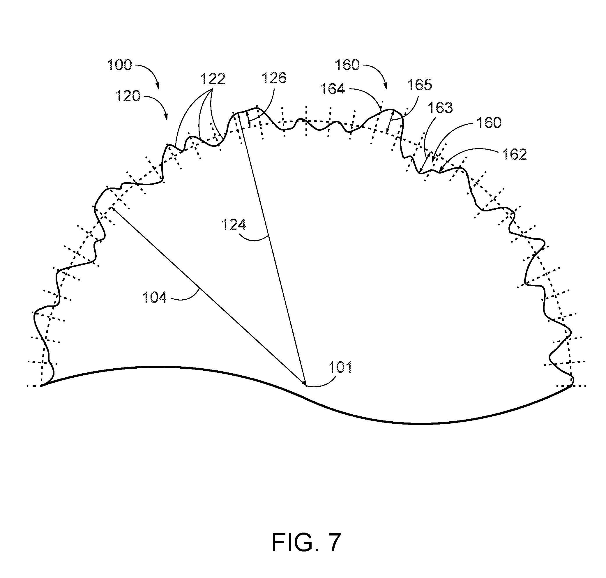
[0012] FIG. 7 is a schematic fragmentary cross-sectional representation of an example of a firearm projectile with a turbulence-inducing surface according to the present disclosure.
[0013] FIG. 8 is a schematic representation of an example of a firearm cartridge in the form of a shot shell that contains a plurality of firearm projectiles in the form of shot pellets according to the present disclosure.
[0014] FIG. 9 is a flow chart illustrating examples of methods for forming firearm projectiles and firearm cartridges according to the present disclosure.
DETAILED DESCRIPTION
[0015] FIGS. 1-9 provide examples of firearm projectiles 100 with turbulence-inducing surfaces 120 according to the present disclosure, of firearm cartridges 10 that include projectiles 100, of turbulence-inducing surfaces 120, and/or of methods 200 for forming firearm projectiles 100 and/or firearm cartridges 10. Elements that serve a similar, or at least substantially similar, purpose are labeled with like numbers in each of FIGS. 1-9, and these elements may not be discussed in detail herein with reference to each of FIGS. 1-9. Similarly, all elements may not be labeled in each of FIGS. 1-9, but reference numbers associated therewith may be utilized herein for consistency. Elements, components, and/or features that are discussed herein with reference to one or more of FIGS. 1-9 may be included in and/or utilized with the subject matter of any of FIGS. 1-9 without departing from the scope of the present disclosure.
[0016] In general, elements that are likely to be included in a given (i.e., a particular) embodiment are illustrated in solid lines, while elements that are optional to a given embodiment are illustrated in dashed lines. However, elements that are shown in solid lines are not essential to all embodiments, and an element shown in solid lines may be omitted from a given embodiment without departing from the scope of the present disclosure.
[0017] FIG. 1 schematically illustrates an example of a firearm projectile 100 according to the present disclosure. As schematically illustrated in FIG. 1, firearm projectile 100 includes a projectile body 110 and a turbulence-inducing surface 120 that at least substantially encloses, or covers, projectile body 110. Turbulence-inducing surface 120 additionally or alternatively may be described as forming at least a portion of, and optionally at least a substantial portion or all of, the exterior surface of firearm projectile 100. Turbulence-inducing surface 120 generally is configured to optimize drag properties of firearm projectile 100 during ballistic flight thereof, as described herein. While projectile body 110 and turbulence-inducing surface 120 generally are described herein as being distinct components of firearm projectile 100, it is within the scope of the present disclosure that projectile body 110 and turbulence-inducing surface 120 refer to respective regions, portions, and/or features of firearm projectile 100. For example, projectile body 110 and turbulence-inducing surface 120 may be formed of the same material. As a more specific example, turbulence-inducing surface 120 may be formed of the same material as the projectile body and may be integral with projectile body 110. In such examples, turbulence-inducing surface 120 may refer and/or correspond to a surface region of firearm projectile 100 such that projectile body 110 is continuous with turbulence-inducing surface 120.
[0018] As described in more detail herein, turbulence-inducing surface 120 generally is configured to reduce a drag coefficient of firearm projectile 100, such as relative to an otherwise identical firearm projectile that lacks the turbulence-inducing surface. Accordingly, firearm projectiles 100 with turbulence-inducing surfaces 120 fired from a firearm with a given initial (muzzle) velocity may travel farther, may retain a greater proportion of their initial velocity upon impacting a target, may deliver a greater kinetic energy to a target, and/or may deliver a greater lethality per firearm projectile, when compared to conventional firearm projectiles that lack turbulence-inducing surfaces 120 as described herein. Additionally or alternatively, firearm cartridges that include firearm projectiles 100 as described herein may include less propellant and/or fewer firearm projectiles relative to conventional firearm cartridges that include firearm projectiles without turbulence-inducing surfaces while retaining performance metrics (such as lethality per cartridge and/or lethality per firearm projectile) similar to those of conventional firearm cartridges with firearm projectiles that do not include turbulence-inducing surfaces 120.
[0019] As schematically illustrated in FIG. 1, firearm projectile 100 may be a shot pellet 150 that is at least substantially spherical with a diameter 102. However, this is not required to all examples of firearm projectile 100, and it is additionally within the scope of the present disclosure that firearm projectile 100 may be any appropriate firearm projectile that includes turbulence-inducing surface 120. Additionally or alternatively, firearm projectile 100 may be at least substantially spherical without also being a shot pellet. Moreover, while the present disclosure generally relates to examples in which a firearm projectile is at least substantially spherical, this is not required to all examples of firearm projectile 100, and it is additionally within the scope of the present disclosure that firearm projectile 100 may have any appropriate non-spherical shape suitable for a firearm projectile. Additionally or alternatively, it is within the scope of the present disclosure that firearm projectile 100 may include and/or be a projectile for use in a military context, such as an artillery shell.
[0020] Firearm projectile 100 may have any appropriate dimensions and/or material construction. As examples, diameter 102 may have any appropriate value, examples of which include at least 1 millimeter (mm), at least 1.5 mm, at least 2 mm, at least 2.5 mm, at least 3 mm, at least 3.5 mm, at least 4 mm, at least 4.5 mm, at least 5 mm, at least 6 mm, at least 7 mm, at least 8 mm, at least 9 mm, at least 10 mm, at least 15 mm, at least 20 mm, at most 25 mm, at most 17 mm, at most 12 mm, at most 9.5 mm, at most 8.5 mm, at most 7.5 mm, at most 6.5 mm, at most 5.5 mm, at most 4.7 mm, at most 4.2 mm, at most 3.7 mm, at most 3.2 mm, at most 2.7 mm, at most 2.2 mm, at most 1.7 mm, and/or at most 1.2 mm.
[0021] Firearm projectile 100, projectile body 110, and/or turbulence-inducing surface 120 may be formed of any appropriate material(s). For example, firearm projectile 100, projectile body 110, and/or turbulence-enhancing surface 120 may be at least substantially formed from metal, with more specific examples including at least 90%, at least 93%, at least 95%, at least 97%, at least 98%, at least 99%, 90-96%, 93-97%, 95-98%, 96-99.5%, or 100% of firearm projectile 100, projectile body 110, and/or turbulence-enhancing surface 120 being formed from metal. Examples of suitable metals include one or more of lead, steel, iron, copper, zinc, nickel, tungsten, bismuth, tin, cobalt, aluminum, steel, bronze, manganese, and/or alloys and/or mixtures thereof. In examples in which firearm projectile 100, projectile body 110, and/or turbulence-inducing surface 120 is not entirely formed from metal, the remaining portion of firearm projectile 100, projectile body 110, and/or turbulence-inducing surface 120 may be formed from other suitable non-metallic components, such as a wax, binder, corrosion inhibitor, anti-sparking agent, sealant, and/or oxidation inhibitor. Examples of compositions for firearm projectiles 100, projectile bodies 110, and/or turbulence-inducing surfaces 120 are disclosed in U.S. Pat. Nos. 9,528,804, 8,171,849, 7,267,794, 7,059,233, 6,527,880, and 6,447,715, the disclosures of which are hereby incorporated by reference for all purposes.
[0022] Firearm projectile 100 may have any appropriate mass density, examples of which include at least 6 grams per cubic centimeter (g/cc), at least 6.5 g/cc, at least 7 g/cc, at least 7.5 g/cc, at least 8 g/cc, at least 8.5 g/cc, at least 9.0 g/cc, at least 9.5 g/cc, at most 10 g/cc, at least 10.5 g/cc, at least 11 g/cc, at least 11.5 g/cc, at least 12 g/cc, at least 13 g/cc, at least 13.5 g/cc, at least 14 g/cc, at least 14.5 g/cc, at least 15 g/cc, at most 16 g/cc, at most 15 g/cc, at most 14 g/cc, at most 13 g/cc, at most 12 g/cc, at most 11.5 g/cc, at most 11 g/cc, at most 10 g/cc, at most 9.5 g/cc, at most 9 g/cc, at most 8.5 g/cc, at most 8.0 g/cc, at most 7.5 g/cc, and/or at most 7.0 g/cc. As discussed herein, firearm projectile 100 may have a mass density that is less than that of conventional firearm projectiles, such as lead-based firearm projectiles, but which may deliver similar and/or augmented kinetic energy and/or lethality to a target by virtue of improved velocity retention during flight thereof.
[0023] Turbulence-inducing surface 120 may be configured to optimize the ballistic and/or aerodynamic properties of firearm projectile 100 in any appropriate manner, such as by reducing a drag force exerted upon the firearm projectile as the projectile travels through air. As will be appreciated by one skilled in the art of fluid dynamics, the magnitude of the drag force F.sub.D exerted upon an object traveling through a fluid may be expressed as F.sub.D=.rho.u.sup.2C.sub.DA, where .rho. is the mass density of the fluid, u is the velocity of the object relative the fluid, C.sub.D is a drag coefficient, and A is the cross-sectional area of the object. Thus, for a projectile of a given diameter traveling through air with a given velocity, the drag force generally is directly proportional to the drag coefficient.
[0024] Turbulence-inducing surface 120 generally is configured to reduce a drag coefficient of firearm projectile 100 relative to that of a smooth spherical projectile of the same material composition and mass as firearm projectile 100, thereby reducing the drag force exerted upon firearm projectile 100 when traveling through a given fluid with a given velocity. For example, and as schematically illustrated in FIG. 1 and as discussed in more detail herein, turbulence-inducing surface 120 may include a plurality of surface features 160, such as may be collectively configured to reduce a drag coefficient of firearm projectile 100. As discussed herein, the drag coefficient of a given object generally depends upon a velocity of the object with respect to a fluid medium through which the object travels. Accordingly, firearm projectile 100 may be described more specifically as having a drag coefficient when traveling through air at a given velocity that is less than a drag coefficient of a smooth spherical projectile of the same mass and material composition as firearm projectile 100 and that lacks turbulence-inducing surface 120 when the smooth spherical projectile travels through air with the given velocity. As yet more specific examples, firearm projectile 100 may have a drag coefficient, when traveling through air at a given velocity, that is at least 0.1 times, at least 0.25 times, at least 0.35 times, at least 0.45 times, at least 0.55 times, at least 0.65 times, at least 0.75 times, at least 0.85 times, at most 0.9 times, at most 0.8 times, at most 0.7 times, at most 0.6 times, at most 0.5 times, at most 0.4 times, at most 0.3 times, and/or at most 0.2 times a drag coefficient of the smooth spherical projectile of the same mass and material composition as firearm projectile 100.
[0025] As used herein, references to firearm projectile 100 traveling through air, and numerical quantities associated therewith, generally may refer to examples in which the firearm projectile travels through air at sea level pressure (e.g., at a pressure of 101,325 Pascals) and at 0.degree. Celsius. However, this is not required to all examples of firearm projectile 100, and it is additionally within the scope of the present disclosure that firearm projectile 100 may exhibit advantageous ballistic properties as described herein when traveling through air that has any appropriate temperature and/or pressure.
[0026] As used herein, the term "velocity," as used to characterize a flow of fluid around an object or a motion of an object through a fluid, is intended to refer to a magnitude of a relative speed between the object and the fluid. Examples (such as numerical examples) of velocities provided herein may refer to and/or be determined via any appropriate measurement technique, such as may be applicable and/or known to the field of firearm ballistics. As examples, a velocity of firearm projectile 100 subsequent to being fired from a firearm may be determined via any appropriate mechanism, examples of which include Doppler measurements, laser measurements, photographic measurements, and/or kinematic measurements. As more specific examples, a velocity of firearm projectile 100 may be determined via measurement of a penetration of the firearm projectile into a ballistic gel of a known density. Additionally or alternatively, a velocity of firearm projectile 100 may be determined via a ballistic pendulum apparatus. As further examples, a velocity of firearm projectile 100 through a fluid may refer to a velocity of a fluid (such as air) that is propelled relative to a substantially stationary firearm projectile, such as by mounting the firearm projectile in a wind tunnel apparatus. In such an example, the wind tunnel apparatus also may be configured to provide a direct measurement of a drag force exerted upon firearm projectile 100 by the fluid flow at a given fluid velocity.
[0027] As used herein, references to turbulence-inducing surface 120 yielding firearm projectile 100 with a reduced, lower, increased, higher, improved, augmented, etc. aerodynamic property (such as a lower drag coefficient and/or a greater velocity upon impact) generally refer to a comparison between firearm projectile 100 and an otherwise identical firearm projectile that lacks turbulence-inducing surface 120. As examples, the otherwise identical firearm projectile may have the same mass, density, diameter, and/or material construction as firearm projectile 100, and/or may have an exterior surface that is smooth, such as substantially smooth, perfectly smooth, substantially spherical, and/or perfectly spherical.
[0028] The drag coefficient of a given object traveling through a fluid with a given velocity generally is dependent upon the velocity of the object relative to the fluid. As will be appreciated by one skilled in the art of fluid dynamics, the behavior of the flow of a conventional fluid such as air around a solid body traveling through the fluid may be characterized as "laminar," which generally is associated with lower velocities, or "turbulent," which is generally associated with higher velocities. As discussed in more detail herein, the relationship between drag coefficient and velocity may vary depending upon whether the fluid flow is in a laminar regime or a turbulent regime. These distinct regimes of fluid flow may be characterized via reference to the dimensionless Reynolds number (Re), defined as Re=uD/v, where u is the velocity of the object relative to the fluid, D is the diameter of the object, and v is the kinematic viscosity of the fluid. Thus, for a given object with a given diameter traveling through a given fluid, the Reynolds number is directly proportional to the relative velocity between the object and the fluid.
[0029] As used herein, the terms "turbulence" and "turbulent," as used to describe a flow characteristic of a fluid, refer generally to a flow state in which flow characteristics (such as pressure and/or flow velocity) are chaotic, random, and/or disordered. In this manner, turbulent flow generally stands in contrast to laminar flow, which in turn refers generally to a flow state in which fluid flow exhibits ordered, parallel layers. A transition between laminar flow and turbulent flow may occur in a spatial sense, for example, such as in which a fluid flow around an object exhibits regions of laminar flow and regions of turbulent flow. Additionally or alternatively, a transition between laminar flow and turbulent flow may occur in a dynamic sense, for example, such as in which increasing the velocity of an object through a fluid serves to introduce turbulence into a region, relative to the object, that exhibits laminar flow at lower velocities. Accordingly, as used herein, the phrase "inducing turbulence" (and the like) generally may refer to an onset in turbulent flow in a region relative to an object that previously exhibited laminar flow.
[0030] As discussed, the drag coefficient of an object traveling relative to a fluid with a velocity generally depends on the velocity, which in turn may be associated with a Reynolds number describing the flow characteristics. FIG. 2 is a graph illustrating plots of drag coefficient C.sub.D as a function of the Reynolds number Re for spheres with varying surface characteristics. Specifically, curve 1 plots C.sub.D vs. Re for a smooth sphere, while curves 2-5 plot C.sub.D vs. Re for spheres with increasing degrees of surface roughness, with curve 5 representing the greatest degree of surface roughness. As seen in FIG. 2, the drag coefficient of a smooth sphere falls abruptly from about 0.5 to about 0.1 at a Reynolds number of about 300,000. This phenomenon, known in the art of fluid dynamics as the "drag crisis," is associated with a transition from laminar flow to turbulent flow in a boundary layer of fluid flow immediately adjacent to the sphere, thereby narrowing a turbulent wake formed behind the sphere and reducing a pressure drag exerted on the sphere as a result of the turbulent wake.
[0031] As used herein, the term "about," as used to characterize a quantity with respect to a reference number, may indicate that the quantity is equal to the reference number, is at least substantially equal to the reference number, falls within an absolute range relative to the reference number, and/or falls within a percentage variation relative to the reference number. As examples, a drag coefficient that is described as being about equal to a reference drag coefficient may differ from the reference drag coefficient by a difference of at most 0.1, at most 0.075, at most 0.05, at least 0, and/or 0. As additional examples, a Reynolds number that is described as being about equal to a reference Reynolds number may differ from the reference Reynolds number by at most 40%, at most 30%, at most 20%, at most 10%, at most 5%, at least 0%, and/or 0%.
[0032] With continued reference to FIG. 2, the velocity-dependent drag coefficient of a nominally spherical projectile may be altered via the introduction of surface roughness onto the projectile. As discussed, introducing roughness onto an exterior surface of a projectile, such as via turbulence-inducing surface 102, may serve to introduce turbulence into the boundary flow layer adjacent to the projectile at lower velocities, thereby shifting a critical Reynolds number at which the drag crisis occurs to lower values. Specifically, FIG. 2 illustrates plots of drag coefficient as a function of Reynolds numbers for spheres characterized by relative roughness values of 0.15% (curve 2), 0.5% (curve 3), and 1.25% (curve 4). In the context of FIG. 2, relative roughness is defined as a ratio of a sand roughness of the sphere to a diameter of the sphere. Curve 5 is a plot of drag coefficient vs. Reynolds number for a dimpled sphere, such as a golf ball. As seen in FIG. 2, increasing a degree of surface roughness may lead to a decrease in the value of the critical Reynolds number--and, hence, a decrease in the value of a critical velocity--above which the drag coefficient of the given projectile falls to a reduced value. Accordingly, turbulence-inducing surface 120 may be roughened and/or otherwise configured such that firearm projectile 100 is expected to travel at velocities in excess of this critical velocity during its flight, thereby enabling firearm projectile 100 to travel with a reduced drag coefficient during the course of its flight relative to a substantially smooth spherical projectile of the diameter 102. As examples, turbulence-inducing surface 120 of firearm projectile 100 may be configured to induce turbulence in a boundary layer of air adjacent to the firearm projectile when the firearm projectile traveling through air has a Reynolds number that is less than 300,000, less than 200,000, less than 100,000, and/or greater than 10,000. Additionally or alternatively, turbulence-inducing surface 120 of firearm projectile 100 may be configured to induce a drag crisis in the drag coefficient of the firearm projectile when the firearm projectile traveling through air has a critical Reynolds number that is less than 300,000, less than 200,000, less than 100,000, and/or greater than 10,000.
[0033] Firearm projectile 100 may have any appropriate drag coefficient, such as may depend upon a velocity and/or a Reynolds number thereof. For example, when firearm projectile 100 traveling through air has a Reynolds number that is less than 300,000, the firearm projectile may have a drag coefficient that is less than 0.35. Additionally or alternatively, firearm projectile 100 may be described as having a drag coefficient that is less than about 0.35 when the firearm projectile traveling through air has a Reynolds number that is less than a maximum ballistic Reynolds number and greater than a minimum ballistic Reynolds number. As used herein, the maximum ballistic Reynolds number may correspond to a maximum Reynolds number experienced during a flight of firearm projectile 100 (such as immediately after being discharged from the barrel of a firearm), while the minimum ballistic Reynolds number may correspond to a minimum Reynolds number experienced during the flight of the firearm projectile (such as immediately before impacting a target). As examples, the maximum ballistic Reynolds number may correspond to the muzzle velocity of firearm projectile 100 (such as 457 m/s (1,500 feet/s)), and/or the minimum ballistic Reynolds number may correspond to the velocity of the firearm projectile subsequent to traveling a distance of 36.6 m (40 yards). More specific examples include the following, which may correspond to firearm projectiles 100 traveling through air with a pressure of 101,325 Pascals and a temperature of 0.degree. Celsius:
[0034] Example 1: Firearm projectile 100 may be a BBB shot pellet 150 with diameter 102 of 4.83 mm (0.19 inches (in.)), the maximum ballistic Reynolds number may be about 166,000, and the minimum ballistic Reynolds number may be about 128,000.
[0035] Example 2: Firearm projectile 100 may be a BB shot pellet 150 with diameter 102 of 4.57 mm (0.18 in.), the maximum ballistic Reynolds number may be about 157,000, and the minimum ballistic Reynolds number may be about 119,000.
[0036] Example 3: Firearm projectile 100 may be a B shot pellet 150 with diameter 102 of 4.32 mm (0.17 in.), the maximum ballistic Reynolds number may be about 148,000, and the minimum ballistic Reynolds number may be about 112,000.
[0037] Example 4: Firearm projectile 100 may be a #1 shot pellet 150 with diameter 102 of 4.06 mm (0.16 in.), the maximum ballistic Reynolds number may be about 140,000, and the minimum ballistic Reynolds number may be about 104,000.
[0038] Example 5: Firearm projectile 100 may be a #2 shot pellet 150 with diameter 102 of 3.81 mm (0.15 in.), the maximum ballistic Reynolds number may be about 131,000, and the minimum ballistic Reynolds number may be about 96,800.
[0039] Example 6: Firearm projectile 100 may be a #3 shot pellet 150 with diameter 102 of 3.56 mm (0.14 in.), the maximum ballistic Reynolds number may be about 122,000, and the minimum ballistic Reynolds number may be about 89,200.
[0040] Example 7: Firearm projectile 100 may be a #4 shot pellet 150 with diameter 102 of 3.30 mm (0.13 in.), the maximum ballistic Reynolds number may be about 114,000, and the minimum ballistic Reynolds number may be about 81,700.
[0041] Example 8: Firearm projectile 100 may be a #5 shot pellet 150 with diameter 102 of 3.05 mm (0.12 in.), the maximum ballistic Reynolds number may be about 105,000, and the minimum ballistic Reynolds number may be about 74,200.
[0042] Example 9: Firearm projectile 100 may be a #6 shot pellet 150 with diameter 102 of 2.79 mm (0.11 in.), the maximum ballistic Reynolds number may be about 96,000, and the minimum ballistic Reynolds number may be about 66,800.
[0043] Example 10: Firearm projectile 100 may be a #7 shot pellet 150 with diameter 102 of 2.54 mm (0.10 in.), the maximum ballistic Reynolds number may be about 88,000, and the minimum ballistic Reynolds number may be about 59,500.
[0044] Example 11: Firearm projectile 100 may be a #71/2 shot pellet 150 with diameter 102 of 2.41 mm (0.095 in.), the maximum ballistic Reynolds number may be about 83,000, and the minimum ballistic Reynolds number may be about 55,800.
[0045] Example 12: Firearm projectile 100 may be a #8 shot pellet 150 with diameter 102 of 2.29 mm (0.090 in.), the maximum ballistic Reynolds number may be about 79,000, and the minimum ballistic Reynolds number may be about 52,200.
[0046] Firearm projectile 100 additionally or alternatively may be described as having a drag coefficient that is at least substantially constant during flight thereof. As examples, firearm projectile 100 may have a drag coefficient that is at least substantially constant, constant to within 50%, and/or constant to within 20% when the firearm projectile traveling through air has a Reynolds number that is less than the maximum ballistic Reynolds number and greater than the minimum ballistic Reynolds number of the firearm projectile.
[0047] Turning now to FIGS. 3-6, turbulence-inducing surface 120 may include and/or be any appropriate form, quality, dimension, and/or distribution of surface features 160 for reducing a drag coefficient of firearm projectile 100 as described herein. Specifically, FIG. 3 schematically illustrates examples of turbulence-inducing surfaces 120, while FIGS. 4-6 provide less schematic illustrations of firearm projectiles 100 in the form of shot pellets 150 including examples of turbulence-inducing surfaces 120.
[0048] The plurality of surface features 160 may include and/or be any appropriate features. For example, and as schematically illustrated in FIG. 3, the plurality of surface features 160 may include one or more depressions 162 and/or one or more protrusions 164. As examples, each depression 162 may include and/or be an indentation, a crater, a dimple, an etch, a channel, a groove, and/or a scratch. As additional examples, each protrusion 164 may include and/or be a bump, a pimple, a ridge, an edge, and/or a raised rim. As additionally schematically illustrated in FIG. 3, turbulence-inducing surface 120 and/or the plurality of surface features 160 may be described as including one or more localized surface features, such as depressions 162, indentations, craters, dimples, protrusions 164, bumps, and/or pimples. Additionally or alternatively, turbulence-inducing surface 120 may include one or more elongate surface features, such as ridges, edges, channels, grooves, and/or scratches. In an example in which turbulence-inducing surface 120 includes a plurality of elongate surface features, two or more of the elongate surface features may be randomly oriented with respect to one another and optionally may intersect and/or partially overlap. Additionally or alternatively, two or more of the elongate surface features may be at least substantially parallel to one another.
[0049] As a more specific example, and as schematically illustrated in FIG. 3, turbulence-inducing surface 120 may include and/or be an etched surface 132 in which the plurality of surface features 160 includes a plurality of channels and/or grooves. In such an example, the plurality of channels and/or grooves also may be referred to as a network and/or a mosaic of channels and/or grooves. Etched surface 132 may be formed via any appropriate process, such as via a chemical etching process, examples of which are described herein. FIG. 4 illustrates an example of firearm projectile 100 in the form of shot pellet 150 with turbulence-inducing surface 120 in the form of etched surface 132.
[0050] As another example, and as further schematically illustrated in FIG. 3, turbulence-inducing surface 120 may include and/or be a mechanically abraded surface 134, in which the plurality of surface features 160 includes a plurality of scratches. Mechanically abraded surface 134 may be formed via any appropriate process, such as via a mechanical abrading process, examples of which are described herein. FIG. 5 illustrates an example of firearm projectile 100 in the form of shot pellet 150 with turbulence-inducing surface 120 in the form of mechanically abraded surface 134 with a plurality of randomly oriented scratches.
[0051] As another example, and as further schematically illustrated in FIG. 3, turbulence-inducing surface 120 may include and/or be an abrasively blasted surface 136, in which the plurality of surface features 160 includes a plurality of depressions 162. In such an example, at least one depression 162 of the plurality of depressions may be at least substantially surrounded by a raised ridge and/or rim, and/or may take the appearance of a crater. Abrasively blasted surface 136 may be formed via any appropriate process, such as via an abrasive blasting process, examples of which are described herein. FIG. 6 illustrates an example of firearm projectile 100 in the form of shot pellet 150 with turbulence-inducing surface 120 in the form of abrasively blasted surface 136 with a plurality of depressions substantially surrounded by raised rims (e.g., that are raised relative to a portion of the turbulence-inducing surface immediately adjacent depression 162).
[0052] As additional examples, and as discussed, turbulence-inducing surface 120 may include a plurality of protrusions 164, such as bumps and/or ridges. As more specific examples, and as further schematically illustrated in FIG. 3, turbulence-inducing surface 120 may include and/or be a sparsely textured surface 138, in which the plurality of protrusions 164 includes a plurality of spaced-apart protrusions 164, and/or may include and/or be a densely textured surface 140, in which the plurality of protrusions 164 includes a plurality of closely adjacent and/or at least partially overlapping protrusions 164. Sparsely textured surface 138 and/or densely textured surface 140 each may be formed via any appropriate respective processes, such as any of the processes discussed herein. As an additional example, and as further schematically illustrated in FIG. 3, turbulence-inducing surface 120 may include and/or be a polyhedral surface 142, in which the plurality of surface features 160 includes one or more substantially flat facets 166.
[0053] It additionally is within the scope of the present disclosure that turbulence-inducing surface 120 may include any appropriate combination of surface features as discussed herein. For example, turbulence-inducing surface 120 may include a first surface feature 160 at least partially superimposed upon a second surface feature 160, in which each of the first surface feature and the second surface feature is a dimple, a depression, a recess, a channel, a groove, a ridge, a raised rim, a protrusion, a pimple, a bump, or a facet.
[0054] Turbulence-inducing surface 120 may be characterized and/or quantified in any appropriate manner, such as in any appropriate geometrical, mathematical, and/or statistical manner. For example, and as schematically illustrated in FIG. 1, turbulence-inducing surface 120 may be described as consisting of a plurality of non-overlapping surface loci 122 that collectively form the turbulence-inducing surface. FIG. 7 is a schematic cross-sectional representation of turbulence-inducing surface 120 of firearm projectile 100, segmented into a plurality of surface loci 122. As schematically illustrated in FIG. 7, each surface locus 122 of the plurality of surface loci may be described as having a corresponding locus radius 124, as measured between the surface locus and a center point 101 of firearm projectile 100. Locus radius 124 may be measured between center point 101 and any appropriate point on surface locus 122, such as a center point of the surface locus. As further schematically illustrated in FIG. 7, firearm projectile 100 may be characterized by a reference radius 104. Reference radius 104 may be any appropriate dimension of firearm projectile 100, such as a radius of projectile body 110, a maximum radius of firearm projectile 100, a minimum radius of the firearm projectile, and/or the arithmetic mean of the corresponding locus radii 124 of the plurality of surface loci 122. As further schematically illustrated in FIG. 7, each surface locus 122 further may be characterized by a corresponding radial deviation 126 that is equal to the corresponding locus radius 124 minus the reference radius 104. Thus, radial deviation 126 may be a positive quantity or a negative quantity. In this manner, firearm projectile 100 and/or turbulence-inducing surface 120 may be characterized by a roughness metric that is based, at least in part, on the set of corresponding radial deviations of the plurality of surface loci 122. As discussed herein, the roughness metric may include and/or be an individual quantity or a set of quantities, such as a set of metrics that collectively describe firearm projectile 100 and/or turbulence-inducing surface 120.
[0055] The roughness metric characterizing turbulence-inducing surface 120 may include and/or be any appropriate metric and/or measure corresponding to the set of radial deviations 126. For example, the roughness metric may include and/or be an arithmetical mean deviation, defined as the arithmetic mean of the absolute values of the set of corresponding radial deviations 126 of the plurality of surface loci 122. Additionally or alternatively, the roughness metric may include and/or be a root mean squared deviation, defined as the square root of the arithmetic mean of the squares of the set of corresponding radial deviations 126 of the plurality of surface loci 122.
[0056] As additional examples, the roughness metric characterizing turbulence-inducing surface 120 may include and/or be a normalized central moment of order n (such that n is an integer greater than 2), defined as the arithmetic mean of the nth power of each of the corresponding radial deviations 126 of the plurality of surface loci 122 divided by the nth power of the root mean squared deviation of the corresponding radial deviations 126 of the plurality of surface loci 122. As a more specific example, n may be equal to 3, such that the normalized central moment is a measure of the skewness of the set of radial deviations 126. In such an example, the normalized central moment may be a positive quantity or a negative quantity. As another example, n may be equal to 4, such that the normalized central moment is a measure of the kurtosis of the set of radial deviations 126. In general, n may assume any positive integer value, with higher values of n corresponding to higher-order normalized central moments that describe the set of radial deviations 126 with varying degrees of precision and/or detail.
[0057] As further examples, the roughness metric may include and/or be a maximum positive deviation and/or a maximum negative deviation, respectively defined as the maximum value and the minimum value of the set of corresponding radial deviations 126 of the plurality of surface loci 122. Additionally or alternatively, the roughness metric may include and/or be a radial range, defined as the absolute difference between the maximum positive deviation and the maximum negative deviation.
[0058] The roughness metric may be understood as characterizing turbulence-inducing surface 120 in any appropriate manner. For example, the roughness metric may be at least partially based upon, and/or may be equal to, a characteristic roughness depth of turbulence-inducing surface 120. As more specific examples, the characteristic roughness depth may be equal to a sand roughness, the arithmetical mean deviation, the root means squared deviation, the normalized central moment of order n, and/or any other appropriate measure characterizing turbulence-inducing surface 120. The characteristic roughness depth may have any appropriate value, such as for reducing the drag coefficient of firearm projectile 100 as described herein. As example, the characteristic roughness depth may be at least 1 micrometer (.mu.m), at least 3 .mu.m, at least 5 .mu.m, at least 30 .mu.m, at least 50 .mu.m, at least 100 .mu.m, at least 300 .mu.m, at least 500 .mu.m, at least 1 mm, at most 2 mm, at most 700 .mu.m, at most 200 .mu.m, at most 70 .mu.m, at most 20 .mu.m, at most 7 .mu.m, and/or at most 2 .mu.m.
[0059] Additionally or alternatively, the roughness metric may include and/or be a relative roughness ratio, which may be defined as the ratio of the characteristic roughness depth of turbulence-inducing surface 120 to diameter 102 of firearm projectile 100. The relative roughness ratio may have any appropriate absolute value, examples of which include at least 0.00001, at least 0.00003, at least 0.00005, at least 0.0001, at least 0.0003, at least 0.0005, at least 0.001, at least 0.003, at least 0.005, at least 0.01, at least 0.03, at least 0.05, at most 0.1, at most 0.07, at most 0.035, at most 0.02, at most 0.007, at most 0.002, at most 0.0007, at most 0.0002, at most 0.00007, and/or at most 0.00002.
[0060] Turbulence-inducing surface 120 may be described as including any appropriate number and/or configuration of surface loci 122. As examples, turbulence-inducing surface 120 may include at least 100 surface loci 122, at least 1,000 surface loci, at least 10,000 surface loci, at least 100,000 surface loci, and/or at most 10,000,000 surface loci. For example, each surface locus 122 may occupy substantially the same solid angle and/or surface area, and/or may be evenly distributed across turbulence-inducing surface 120. As used herein, the term "solid angle" refers to a measure of a field of view occupied by a given surface locus 122 as viewed from center point 101 of firearm projectile 100, such that the entirety of turbulence-inducing surface 120 occupies a solid angle of 4.pi.steradians. As examples, each surface locus 122 may occupy a solid angle that is less than 0.1 steradians, less than 0.01 steradians, less than 0.001 steradians, less than 0.0001 steradians, and/or greater than 0 steradians. Additionally or alternatively, each surface locus 122 may occupy a surface area that is less than 1% of a total surface area of turbulence-inducing surface 120, less than 0.1% of the total surface area of the turbulence-inducing surface, less than 0.01% of the total surface area of the turbulence-inducing surface, less than 0.001% of the total surface area of the turbulence-inducing surface, and/or greater than 0% of the total surface area of the turbulence-inducing surface.
[0061] FIG. 7 additionally illustrates examples of surface features 160 that may form and/or be defined by turbulence-inducing surface 120. For example, and as schematically illustrated in FIG. 7, one or more surface loci 122 may include and/or define a depression 162 with a corresponding depression depth 163. Additionally or alternatively, one or more surface loci 122 may include and/or define a protrusion 164 with a protrusion height 165. Depression depth 163 and/or protrusion height 165 may be defined in any appropriate manner. For example, depression depth 163 may be defined as an absolute difference between a minimum radius of firearm projectile 100 within the corresponding depression 162 and reference radius 104. Similarly, protrusion height 165 may be defined as an absolute difference between a maximum radius of firearm projectile 100 within the corresponding protrusion 164 and reference radius 104. As more specific examples, each depression depth 163 and/or each protrusion height 165 may be at least 1 .mu.m, at least 3 .mu.m, at least 5 .mu.m, at least 30 .mu.m, at least 50 .mu.m, at least 100 .mu.m, at least 300 .mu.m, at least 500 .mu.m, at least 1 mm, at most 2 mm, at most 700 .mu.m, at most 200 .mu.m, at most 70 .mu.m, at most 20 .mu.m, at most 7 .mu.m, and/or at most 2 .mu.m. Additionally or alternatively, each depression depth 163 and/or each protrusion height 165 may be less than, greater than, or equal to the characteristic roughness depth of turbulence-inducing surface 120.
[0062] FIG. 8 is a schematic example of a firearm cartridge 10 that includes a plurality of firearm projectiles 100 in the form of shot pellets 150 according to the present disclosure. A firearm cartridge 10 that includes at least one shot pellet 150 may be referred to as a shot shell 14. With reference to FIG. 8, shot shell 14 is shown including a casing, or housing 18 with a head portion 24, a hull portion 17, and a mouth region 36. Shot shell 14 further includes an ignition device 25, such as primer, or priming mixture, 32, which may be configured to ignite propellant 22. Propellant 22 and primer 32 may be located behind a partition 20, such as a wad 31, which serves to segregate the propellant and the primer from a payload 38 of the shot shell and which may provide a gas seal to impede the flow of propellant gases during firing of the firearm cartridge.
[0063] Wad 31 may define and/or be described as defining a shot cup 26, which refers to a portion of the wad that generally faces toward mouth region 36 and which may be contacted by at least a portion of the plurality of shot pellets 150 in the assembled shot shell 14. While FIG. 8 illustrates wad 31 as including a shot cup 26 that is curved, this is not required to all examples of wad 31, and it is additionally within the scope of the present disclosure that wad 31 may be at least substantially flat. For example, wad 31 may take the form of a flat cylindrical disc. Wad 31 additionally or alternatively may be referred to as a shot wad 31, and it may take a variety of suitable shapes and/or sizes. Any suitable size, shape, material, number of components, and/or construction of wad 31 may be used, including but not limited to conventional wads that have been used with lead shot, steel shot, and/or other forms of shot, without departing from the scope of the present disclosure.
[0064] As indicated in FIG. 8, casing 18 may be described as defining an internal chamber, internal compartment, and/or enclosed volume of the shot shell. When the shot shell is assembled, at least propellant 22, wad 31, and payload 38 are inserted into the internal compartment, such as through mouth region 36. After insertion of these components into the internal compartment, mouth region 36 typically is sealed or otherwise closed, such as via any suitable closure 35. As an example, the region of the casing distal head portion 24 may be folded, crimped, or otherwise used to close mouth region 36.
[0065] Payload 38 additionally or alternatively may be referred to as a shot charge, or shot load, 38. Payload 38 typically will include a plurality of shot pellets 150. The region of shot shell 14, casing 18, and/or wad 31 that contains payload 38 may be referred to as a payload region 39 thereof.
[0066] Wad 31 defines a pellet-facing surface 29 that extends and/or faces generally toward mouth region 36 and away from head portion 24 (when the wad is positioned properly within an assembled shot shell). Wad 31 may include at least one gas seal, or gas seal region, 27, and at least one deformable region 28, between the payload region 39 and the propellant 22. Gas seal region 27 is configured to engage the inner surface of the shotgun's chamber and barrel to restrict the passage of gasses, which are produced when the shot shell is fired (i.e., when the charge is ignited), along the shotgun's barrel. By doing so, the gasses propel the wad, and the payload 38 of shot pellets 150 contained therein, from the chamber and along and out of the shotgun's barrel. Deformable region 28 is designed to crumple, collapse, or otherwise non-elastically deform in response to the setback, or firing, forces that are generated when the shot shell is fired and the combustion of the propellant rapidly urges the wad and payload from being stationary to traveling down the barrel of the shotgun at high speeds. Wad 31 may be formed as a single structure or may be formed from two or more connected, adjacent, or spaced-apart components.
[0067] A shot shell 14 may include as few as a single shot pellet 150, which perhaps more appropriately may be referred to as a shot slug, and as many as dozens or hundreds of individual shot pellets 150. The number of shot pellets 150 in any particular shot shell 14 will be defined by such factors as the size and geometry of the shot pellets, the size and shape of the shell's casing and/or wad, the available volume in the casing to be filled by shot pellets 150, etc. For example, a 12-gauge double ought (00) buckshot shell typically contains nine shot pellets having diameters of approximately 0.3 inches (0.762 cm), while shot shells that are intended for use in hunting birds, and especially smaller birds, tend to contain many more shot pellets.
[0068] As discussed, shot shell 14 is designed and/or configured to be placed within a firearm, such as a shotgun, and to fire payload 38 therefrom. As an example, a firing pin of the firearm may strike primer 32, which may ignite propellant 22. Ignition of propellant 22 may produce gasses that may expand and provide a motive force to propel the one or more shot pellets 150 forming payload 38 from the firearm (or a barrel thereof).
[0069] Shot shell 14 and its components have been illustrated schematically in FIG. 8 and are not intended to require a specific shape, size, or quantity of the components thereof. The length and diameter of the overall shot shell 14 and its casing 18, the amount of primer 32 and propellant 22, the shape, size, and configuration of wad 31, the type, shape, size, and/or number of shot pellets 150, etc. all may vary within the scope of the present disclosure.
[0070] Firearm cartridge 10, such as shot shell 14, may be configured to propel firearm projectile 100 with any appropriate initial (muzzle) velocity. As examples, firearm cartridge 10 may be configured to propel firearm projectile 100 (and/or each of a plurality of such firearm projectiles) with a muzzle velocity that is at least 300 meters per second (m/s) (984 feet per second (ft/s)), at least 350 m/s (1,148 ft/s), at least 400 m/s (1,312 ft/s), at least 450 m/s (1,476 ft/s), at least 500 m/s (1,640 ft/s), at least 550 m/s (1,804 ft/s), at most 600 m/s (1,969 ft/s), at most 575 m/s (1,886 ft/s), at most 525 m/s (1,722 ft/s), at most 475 m/s (1,558 ft/s), at most 425 m/s (1,394 ft/s), at most 375 m/s (1,230 ft/s), and at most 325 m/s (1,066 ft/s). Additionally or alternatively, firearm cartridge 10 may be configured to propel firearm projectile 100 (and/or each of a plurality of such firearm projectiles) through air such that the firearm projectile(s) traveling through air has an initial Reynolds number that is at least 70,000, at least 80,000, at least 90,000, at least 100,000, at least 110,000, at least 120,000, at least 130,000, at least 140,000, at least 150,000, at least 160,000, at least 170,000, at least 180,000, at least 190,000, at most 200,000, at most 195,000, at most 185,000, at most 175,000, at most 165,000, at most 155,000, at most 145,000, at most 135,000, at most 125,000, at most 115,000, at most 95,000, at most 85,000, and/or at most 75,000.
[0071] As discussed, firearm projectile 100 generally may be configured to exhibit improved velocity retention upon reaching a target relative to conventional firearm projectiles. Accordingly, firearm cartridge 10 may be configured to propel firearm projectile 100 (and/or each of a plurality of such firearm projectiles) through air such that, when the firearm cartridge is fired horizontally in air, the firearm projectile has a velocity after traveling 36.6 meters (40 yards) that is at least 1.1 times, at least 1.2 times, at least 1.3 times, at least 1.4 times, at least 1.5 times, at least 1.6 times, at least 1.7 times, at least 1.8 times, at least 1.9 times, at most 2 times, at most 1.95 times, at most 1.85 times, at most 1.75 times, at most 1.65 times, at most 1.55 times, at most 1.45 times, at most 1.35 times, at most 1.25 times, and/or at most 1.15 times a velocity of a smooth firearm projectile fired by an otherwise identical firearm cartridge in which the smooth firearm projectile lacks turbulence-inducing surface 120 when the otherwise identical firearm cartridge is fired horizontally in air and after the smooth firearm projectile travels 36.6 meters (40 yards).
[0072] In some examples, such as when utilizing firearm projectiles 100 with diameter 102 of 2.54 mm (0.10 in.) or smaller, it may be desirable that shot shell 14 be configured to propel the firearm projectiles with a higher initial velocity relative to a shot shell containing larger firearm projectiles. For example, because the Reynolds number associated with the motion of firearm projectile 100 through air is proportional to both diameter 102 and the velocity of the firearm projectile relative to the air, a reduction in diameter 102 may motivate a corresponding increase in velocity to maintain the Reynolds number within a desirable range. Accordingly, shot shells 14 that contain comparatively small firearm projectiles 100 (such as with diameter 102 of 2.54 mm or smaller) may include a smaller payload 38 (e.g., a smaller total mass of the payload) and/or a greater charge of propellant 22 relative to shot shells that contain comparatively large firearm projectiles, thereby increasing the total acceleration imparted upon the payload by the propellant.
[0073] FIG. 9 provides examples of methods 200 for forming firearm ammunition such as firearm projectiles 100 with turbulence-inducing surfaces 120 and/or firearm cartridges 10 containing the same according to the present disclosure. The methods presented in FIG. 9 are not intended to be exhaustive or required for production of all firearm projectiles 100 and/or firearm cartridges 10 according to the present disclosure. Similarly, methods 200 may include additional steps and/or substeps without departing from the scope of the present disclosure. Unless a particular step must be completed to enable a subsequent step to be performed, the examples of steps shown and/or discussed in connection with FIG. 9 may be performed in any suitable concurrent and/or sequential order. In the following discussion, reference numerals for the previously discussed turbulence-inducing surfaces 120, firearm projectiles 100, firearm cartridges 10 containing the same, and components thereof are utilized to provide references to the structures shown and discussed with respect to FIGS. 1-8 even though these reference numerals are not shown in FIG. 9.
[0074] As shown in FIG. 9, a method 200 of manufacturing firearm ammunition includes (such as may include and/or be firearm projectile 100) includes providing, at 210, a base projectile that is at least substantially spherical with a smooth exterior surface, and forming, at 216, a turbulence-inducing surface (such as turbulence-inducing surface 120) on the exterior surface of the base projectile. Accordingly, method 200 includes forming a firearm projectile (such as firearm projectile 100) that includes a projectile body (such as projectile body 110) and the turbulence-inducing surface (such as turbulence-inducing surface 120) such that the turbulence-inducing surface at least substantially encloses the projectile body, covers the projectile body, and/or forms the exterior surface of the projectile body.
[0075] The providing the base projectile at 210 may include providing and/or producing the base projectile in any appropriate manner. For example, the providing at 210 may include obtaining the base projectile in the form of a smooth and/or nominally spherical shot pellet. Alternatively, and as shown in FIG. 9, the providing at 210 may include providing, at 212, a projectile precursor that is not substantially spherical and/or not substantially smooth and shaping, at 214, the projectile precursor into the substantially spherical base projectile. In such an example, the projectile precursor may take any appropriate shape and/or form, such as a wire segment, an ovoid, an oblong sphere, and/or an oblate sphere. Additionally or alternatively, in such an example, the shaping at 214 may be performed in any appropriate manner, such as by milling the projectile precursor with an impact mill. In an example in which the providing the base projectile at 210 includes producing the base projectile, the producing may be performed in any appropriate manner, such as via a casting process and/or via a powder metallurgy process. As more specific examples, the producing may include producing via a powder metallurgy process with or without heating and/or sintering steps.
[0076] The forming the turbulence-inducing surface at 216 may be performed in any appropriate manner. For example, the forming the turbulence-inducing surface at 216 may include forming a plurality of surface features (such as surface features 160) on the exterior surface of the base projectile. As a more specific example, and as shown in FIG. 9, the forming at 216 may include adding, at 218, material to the exterior surface of the base projectile, such as by applying a coating or other material to the exterior surface of the base projectile. In such an example, the turbulence-inducing surface may include and/or be the coating and/or other material. Additionally or alternatively, and as further shown in FIG. 9, the forming at 216 may include removing, at 220, material from the base projectile. Additionally or alternatively, and as further shown in FIG. 9, the forming at 216 may include deforming, at 222, the exterior surface of the base projectile, such as via one or more processes as disclosed herein and/or via a plastic deformation process.
[0077] In some examples, the forming the turbulence-inducing surface at 216 may include two or more of the adding material to the exterior surface of the base projectile at 218, the removing material from the base projectile at 220, and the deforming the exterior surface of the base projectile at 222. For example, the forming at 216 may include performing two or more of the adding at 218, the removing at 220, and the deforming at 222 sequentially. As another example, the deforming at 222 additionally or alternatively may be described as including the adding at 218 and/or the removing at 220. Additionally or alternatively, and as shown in FIG. 9, the forming the turbulence-inducing surface at 216 may include chemically etching, at 224, the exterior surface of the base projectile, and/or may include mechanically deforming, at 226, the exterior surface of the base projectile. In an example in which the forming at 216 includes the chemically etching at 224 and the mechanically deforming at 226, the chemically etching at 224 may be performed prior to and/or subsequent to the mechanically deforming at 226.
[0078] In an example of the forming the turbulence-inducing surface at 216 that includes the chemically etching the exterior surface of the base projectile at 224, the chemically etching at 224 may be performed in any appropriate manner sufficient to at least partially form the turbulence-inducing surface. As examples, the chemically etching at 224 may include the removing material from the exterior surface of the base projectile at 220 and/or the deforming the exterior surface of the base projectile at 222, such as via preferentially etching one or more grain boundaries of the exterior surface of the base projectile. The chemically etching at 224 may include etching the exterior surface of the base projectile with any appropriate etchant, examples of which include an acid, a strong acid, and hydrochloric acid. In such examples, the acid may have any appropriate concentration by weight, examples of which include at least 10%, at least 20%, at least 30%, at least 40%, at most 50%, at most 45%, at most 35%, at most 25%, and/or at most 15%.
[0079] The chemically etching at 224 may include submerging the base projectile in the etchant for an etching duration. As examples, the etching duration may be at least 1 minute, at least 5 minutes, at least 10 minutes, at least 15 minutes, at least 20 minutes, at least 30 minutes, at least 60 minutes, at most 75 minutes, at most 45 minutes, at most 25 minutes, at most 17 minutes, at most 12 minutes, and/or at most 7 minutes. The etching duration may be at least partially related to a degree and/or quality of roughness formed on the exterior surface of the base projectile. Additionally or alternatively, the chemically etching at 224 may include etching for an etching duration that is sufficient to produce a passivation layer on the exterior surface of the base projectile, such as may restrict, inhibit, and/or saturate further chemical etching of the exterior surface.
[0080] While the examples of the chemically etching at 224 described herein relate generally to examples in which the exterior surface of the base projectile is dissolved by an acid, this is not required to all examples of the chemically etching at 224, and it is additionally within the scope of the present disclosure that the chemically etching at 224 may include and/or be any appropriate chemical process. As an example, the chemical etching at 224 additionally or alternatively may include oxidizing the exterior surface of the base projectile, such as by heating the base projectile in air. As another example, the chemical etching at 224 additionally or alternatively may include an electrolysis process and/or an electroetching process.
[0081] An example of the turbulence-inducing surface formed via the chemically etching at 224 may have any corresponding surface features and/or characteristics. For example, the chemically etching at 224 may produce an etched surface (such as etched surface 132 as illustrated in FIGS. 3-4), such as via preferential etching of grain boundaries exposed at or near the exterior surface of the base projectile to form a plurality, network, and/or mosaic of grooves and/or channels.
[0082] In an example of the forming the turbulence-inducing surface at 216 that includes the mechanically deforming the exterior surface of the base projectile at 226, the mechanically deforming at 228 may be performed in any appropriate manner to at least partially form the turbulence-inducing surface. As an example, the mechanically deforming at 226 may include and/or be an example of the deforming the exterior surface of the base projectile at 222.
[0083] The mechanically deforming the exterior surface of the base projectile at 226 may include and/or be any appropriate process. For example, the mechanically deforming at 226 may include mechanically abrading the exterior surface of the base projectile via a shear process, such as by rolling the base projectile relative to an abrasive belt. In such an example, the mechanically deforming at 226 may produce a mechanically abraded surface (such as mechanically abraded surface 134 of FIGS. 3 and 5) that includes a plurality of scratches. Mechanically abrading the exterior surface of the base projectile via a shear process may include and/or be an example of the removing material from the exterior surface of the base projectile at 220 and/or the deforming the exterior surface of the base projectile at 222. Stated differently, mechanically abrading the exterior surface of the base projectile may include scratching away material from the exterior surface and/or redistributing material on the exterior surface.
[0084] As another example, the mechanically deforming the exterior surface of the base projectile at 226 may include abrasively blasting the exterior surface of the base projectile, such as by propelling an abrasive medium toward the base projectile. As examples, the abrasive medium may include air, water, sand, grit, pellets, additional base projectiles, and/or firearm projectiles. As more specific examples, the mechanically deforming at 226 may include deforming the exterior surface of the base projectile with a shot blasting apparatus and/or a shot peening apparatus. Representative examples of shot blasting and/or shot peening apparatuses may be produced by the Pangborn Group of Fairburn, Ga., U.S.A and/or by the Norican Group of Taastrup, Denmark. The mechanically deforming at 226 may produce an abrasively blasted surface (such as abrasively blasted surface 136 of FIGS. 3 and 6) that includes a plurality of depressions (such as depressions 162), such as crater-like depressions with raised rims.
[0085] Abrasively blasting the exterior surface of the base projectile may include and/or be an example of the removing material from the exterior surface of the base projectile at 220 and/or the deforming the exterior surface of the base projectile at 222. Stated differently, abrasively blasting the exterior surface of the base projectile may include blasting away material from the exterior surface and/or redistributing material on the exterior surface.
[0086] As yet another example, the mechanically deforming the exterior surface of the base projectile at 226 may include mechanically roughening the exterior surface of the base projectile via a repetitious mechanical roughening process, such as a tumbling process, a rolling process, and/or a milling process. As more specific examples, the repetitious mechanical roughening process may include repeatedly colliding the base projectile with a hammer, a grit, a pellet, a separate base projectile, and a firearm projectile. Mechanically deforming the exterior surface of the base projectile via a repetitious mechanical roughening process may include and/or be an example of the removing material from the exterior surface of the base projectile at 220 and/or the deforming the exterior surface of the base projectile at 222. Stated differently, a mechanical roughening process may include knocking away material from the exterior surface and/or redistributing material on the exterior surface.
[0087] With continued reference to FIG. 9, method 200 may include, subsequent to the forming the turbulence-inducing surface at 216, finishing, at 228, the turbulence-inducing surface. The finishing at 228 may include any appropriate processes and/or steps, such as for removing a byproduct of the forming at 216 from the turbulence-inducing surface and/or for optimizing a material property of the firearm projectile. As examples, and as shown in FIG. 9, the finishing the turbulence-inducing surface at 228 may include cleaning, at 230, the turbulence-inducing surface; polishing, at 232, the turbulence-inducing surface; and/or annealing, at 234, the turbulence-inducing surface.
[0088] As further shown in FIG. 9, method 200 may include, subsequent to the forming the turbulence-inducing surface at 216, assembling, at 236, a firearm cartridge (such as firearm cartridge 10) that includes the firearm projectile. As an example, the firearm cartridge may be a shot shell (such as shot shell 150). In such an example, the assembling the firearm cartridge at 236 may include positioning a primer (such as primer 32) and/or a propellant (such as propellant 22) within a casing (such as casing 18) of the firearm cartridge; positioning a wad (such as wad 31) within the casing; and/or positioning a payload (such as payload 38) into a payload region (such as payload region 39) of the firearm cartridge such that the wad at least substantially separates the propellant and the payload. As discussed herein, forming the turbulence-inducing surface on the firearm projectile may enable the firearm projectile to travel with a reduced drag coefficient relative to an otherwise identical firearm projectile that lacks the turbulence-inducing surface. Accordingly, firearm cartridges produced via methods 200 may include less propellant and/or fewer firearm projectiles relative to conventional firearm cartridges that include firearm projectiles without turbulence-inducing surfaces while retaining performance metrics (such as lethality per cartridge and/or lethality per firearm projectile) similar to those of conventional firearm cartridges.
[0089] As used herein, the term "and/or" placed between a first entity and a second entity means one of (1) the first entity, (2) the second entity, and (3) the first entity and the second entity. Multiple entities listed with "and/or" should be construed in the same manner, i.e., "one or more" of the entities so conjoined. Other entities may optionally be present other than the entities specifically identified by the "and/or" clause, whether related or unrelated to those entities specifically identified. Thus, as a non-limiting example, a reference to "A and/or B," when used in conjunction with open-ended language such as "comprising" may refer, in one embodiment, to A only (optionally including entities other than B); in another embodiment, to B only (optionally including entities other than A); in yet another embodiment, to both A and B (optionally including other entities). These entities may refer to elements, actions, structures, steps, operations, values, and the like.
[0090] As used herein, the phrase "at least one," in reference to a list of one or more entities should be understood to mean at least one entity selected from any one or more of the entity in the list of entities, but not necessarily including at least one of each and every entity specifically listed within the list of entities and not excluding any combinations of entities in the list of entities. This definition also allows that entities may optionally be present other than the entities specifically identified within the list of entities to which the phrase "at least one" refers, whether related or unrelated to those entities specifically identified. Thus, as a non-limiting example, "at least one of A and B" (or, equivalently, "at least one of A or B," or, equivalently "at least one of A and/or B") may refer, in one embodiment, to at least one, optionally including more than one, A, with no B present (and optionally including entities other than B); in another embodiment, to at least one, optionally including more than one, B, with no A present (and optionally including entities other than A); in yet another embodiment, to at least one, optionally including more than one, A, and at least one, optionally including more than one, B (and optionally including other entities). In other words, the phrases "at least one," "one or more," and "and/or" are open-ended expressions that are both conjunctive and disjunctive in operation. For example, each of the expressions "at least one of A, B, and C," "at least one of A, B, or C," "one or more of A, B, and C," "one or more of A, B, or C" and "A, B, and/or C" may mean A alone, B alone, C alone, A and B together, A and C together, B and C together, A, B, and C together, and optionally any of the above in combination with at least one other entity.
[0091] As used herein, "at least substantially," when modifying a degree or relationship, includes not only the recited "substantial" degree or relationship, but also the full extent of the recited degree or relationship. A substantial amount of a recited degree or relationship may include at least 75% of the recited degree or relationship. For example, an object that is at least substantially formed from a material includes an object for which at least 75% of the object is formed from the material and also includes an object that is completely formed from the material. As another example, a first length that is at least substantially as long as a second length includes a first length that is at least 75% as long as the second length and also includes a first length that is as long as the second length.
[0092] As used herein, the phrase, "for example," the phrase, "as an example," and/or simply the term "example," when used with reference to one or more components, features, details, structures, embodiments, and/or methods according to the present disclosure, are intended to convey that the described component, feature, detail, structure, embodiment, and/or method is an illustrative, non-exclusive example of components, features, details, structures, embodiments, and/or methods according to the present disclosure. Thus, the described component, feature, detail, structure, embodiment, and/or method is not intended to be limiting, required, or exclusive/exhaustive; and other components, features, details, structures, embodiments, and/or methods, including structurally and/or functionally similar and/or equivalent components, features, details, structures, embodiments, and/or methods, are also within the scope of the present disclosure.
[0093] In the event that any patents, patent applications, or other references are incorporated by reference herein and (1) define a term in a manner that is inconsistent with and/or (2) are otherwise inconsistent with, either the non-incorporated portion of the present disclosure or any of the other incorporated references, the non-incorporated portion of the present disclosure shall control, and the term or incorporated disclosure therein shall only control with respect to the reference in which the term is defined and/or the incorporated disclosure was present originally.
[0094] As used herein the terms "adapted" and "configured" mean that the element, component, or other subject matter is designed and/or intended to perform a given function. Thus, the use of the terms "adapted" and "configured" should not be construed to mean that a given element, component, or other subject matter is simply "capable of" performing a given function but that the element, component, and/or other subject matter is specifically selected, created, implemented, utilized, programmed, and/or designed for the purpose of performing the function.
[0095] It is also within the scope of the present disclosure that elements, components, and/or other recited subject matter that is recited as being adapted to perform a particular function may additionally or alternatively be described as being configured to perform that function, and vice versa.
[0096] Examples of firearm projectiles, firearm cartridges containing the same, and associated methods are presented in the following enumerated paragraphs.
[0097] A1. A firearm projectile, comprising:
[0098] a projectile body; and
[0099] a turbulence-inducing surface at least substantially enclosing the projectile body.
[0100] A1.1. The firearm projectile of paragraph A1, wherein the firearm projectile is at least substantially spherical.
[0101] A1.2. The firearm projectile of any of paragraphs A1-A1.1, wherein the firearm projectile is a shot pellet.
[0102] A1.3. The firearm projectile of any of paragraphs A1-A1.2, wherein the turbulence-inducing surface is configured to induce turbulence in a boundary layer of air adjacent to the firearm projectile when the firearm projectile travels through air with a Reynolds number that is one or more of less than 300,000, less than 200,000, less than 100,000, and greater than 10,000.
[0103] A1.4. The firearm projectile of any of paragraphs A1-A1.3, wherein the turbulence-inducing surface is configured to induce a drag crisis in a drag coefficient of the firearm projectile when the firearm projectile travels through air with a critical Reynolds number that is one or more of less than 300,000, less than 200,000, less than 100,000, and greater than 10,000.
[0104] A1.5. The firearm projectile of any of paragraphs A1-A1.4, wherein the firearm projectile has a diameter that is one or more of at least 1 millimeter (mm), at least 1.5 mm, at least 2 mm, at least 2.5 mm, at least 3 mm, at least 3.5 mm, at least 4 mm, at least 4.5 mm, at least 5 mm, at least 6 mm, at least 7 mm, at least 8 mm, at least 9 mm, at least 10 mm, at least 15 mm, at least 20 mm, at most 25 mm, at most 17 mm, at most 12 mm, at most 9.5 mm, at most 8.5 mm, at most 7.5 mm, at most 6.5 mm, at most 5.5 mm, at most 4.7 mm, at most 4.2 mm, at most 3.7 mm, at most 3.2 mm, at most 2.7 mm, at most 2.2 mm, at most 1.7 mm, and at most 1.2 mm.
[0105] A1.6. The firearm projectile of any of paragraphs A1-A1.5, wherein the firearm projectile is formed of one or more of lead, steel, iron, copper, zinc, nickel, tungsten, bismuth, tin, cobalt, aluminum, steel, bronze, manganese, and/or alloys and/or mixtures thereof.
[0106] A1.7. The firearm projectile of any of paragraphs A1-A1.6, wherein the firearm projectile has a density of one or more of at least 6 grams per cubic centimeter (g/cc), at least 6.5 g/cc, at least 7 g/cc, at least 7.5 g/cc, at least 8 g/cc, at least 8.5 g/cc, at least 9.0 g/cc, at least 9.5 g/cc, at most 10 g/cc, at least 10.5 g/cc, at least 11 g/cc, at least 11.5 g/cc, at least 12 g/cc, at least 13 g/cc, at least 13.5 g/cc, at least 14 g/cc, at least 14.5 g/cc, at least 15 g/cc, at most 16 g/cc, at most 15 g/cc, at most 14 g/cc, at most 13 g/cc, at most 12 g/cc, at most 11.5 g/cc, at most 11 g/cc, at most 10 g/cc, at most 9.5 g/cc, at most 9 g/cc, at most 8.5 g/cc, at most 8.0 g/cc, at most 7.5 g/cc, and at most 7.0 g/cc.
[0107] A1.8. The firearm projectile of any of paragraphs A1-A1.7, wherein the projectile body and the turbulence-inducing surface are formed of the same material.
[0108] A1.9. The firearm projectile of any of paragraphs A1-A1.8, wherein the turbulence-inducing surface is integral with the projectile body.
[0109] A2.1. The firearm projectile of any of paragraphs A1-A1.9, wherein when the firearm projectile traveling through air has a Reynolds number that is less than 300,000, the firearm projectile has a drag coefficient that is less than 0.35.
[0110] A2.2. The firearm projectile of any of paragraphs A1-A2.1, wherein when the firearm projectile traveling through air has a Reynolds number that is less than a maximum ballistic Reynolds number and greater than a minimum ballistic Reynolds number, the firearm projectile has a drag coefficient that is less than about 0.35.
[0111] A2.3. The firearm projectile of any of paragraphs A1-A2.2, wherein the firearm projectile has a drag coefficient that is at least substantially constant, optionally constant to within 50%, further optionally to within 20%, when traveling through air with a Reynolds number that is less than a/the maximum ballistic Reynolds number and greater than a/the minimum ballistic Reynolds number.
[0112] A2.4. The firearm projectile of any of paragraphs A2.2-A2.3, wherein the firearm projectile is a BBB shot pellet with a diameter of 4.83 mm (0.19 inches (in.)), wherein the maximum ballistic Reynolds number is about 166,000, and wherein the minimum ballistic Reynolds number is about 128,000.
[0113] A2.5. The firearm projectile of any of paragraphs A2.2-A2.3, wherein the firearm projectile is a BB shot pellet with a diameter of 4.57 mm (0.18 in.), wherein the maximum ballistic Reynolds number is about 157,000, and wherein the minimum ballistic Reynolds number is about 119,000.
[0114] A2.6. The firearm projectile of any of paragraphs A2.2-A2.3, wherein the firearm projectile is a B shot pellet with a diameter of 4.32 mm (0.17 in.), wherein the maximum ballistic Reynolds number is about 148,000, and wherein the minimum ballistic Reynolds number is about 112,000.
[0115] A2.7. The firearm projectile of any of paragraphs A2.2-A2.3, wherein the firearm projectile is a #1 shot pellet with a diameter of 4.06 mm (0.16 in.), wherein the maximum ballistic Reynolds number is about 140,000, and wherein the minimum ballistic Reynolds number is about 104,000.
[0116] A2.8. The firearm projectile of any of paragraphs A2.2-A2.3, wherein the firearm projectile is a #2 shot pellet with a diameter of 3.81 mm (0.15 in.), wherein the maximum ballistic Reynolds number is about 131,000, and wherein the minimum ballistic Reynolds number is about 96,800.
[0117] A2.9. The firearm projectile of any of paragraphs A2.2-A2.3, wherein the firearm projectile is a #3 shot pellet with a diameter of 3.56 mm (0.14 in.), wherein the maximum ballistic Reynolds number is about 122,000, and wherein the minimum ballistic Reynolds number is about 89,200.
[0118] A2.10. The firearm projectile of any of paragraphs A2.2-A2.3, wherein the firearm projectile is a #4 shot pellet with a diameter of 3.30 mm (0.13 in.), wherein the maximum ballistic Reynolds number is about 114,000, and wherein the minimum ballistic Reynolds number is about 81,700.
[0119] A2.11. The firearm projectile of any of paragraphs A2.2-A2.3, wherein the firearm projectile is a #5 shot pellet with a diameter of 3.05 mm (0.12 in.), wherein the maximum ballistic Reynolds number is about 105,000, and wherein the minimum ballistic Reynolds number is about 74,200.
[0120] A2.12. The firearm projectile of any of paragraphs A2.2-A2.3, wherein the firearm projectile is a #6 shot pellet with a diameter of 2.79 mm (0.11 in.), wherein the maximum ballistic Reynolds number is about 96,000, and wherein the minimum ballistic Reynolds number is about 66,800.
[0121] A2.13. The firearm projectile of any of paragraphs A2.2-A2.3, wherein the firearm projectile is a #7 shot pellet with a diameter of 2.54 mm (0.10 in.), wherein the maximum ballistic Reynolds number is about 88,000, and wherein the minimum ballistic Reynolds number is about 59,500.
[0122] A2.14. The firearm projectile of any of paragraphs A2.2-A2.3, wherein the firearm projectile is a #71/2 shot pellet with a diameter of 2.41 mm (0.095 in.), wherein the maximum ballistic Reynolds number is about 83,000, and wherein the minimum ballistic Reynolds number is about 55,800.
[0123] A2.15. The firearm projectile of any of paragraphs A2.2-A2.3, wherein the firearm projectile is a #8 shot pellet with a diameter of 2.29 mm (0.090 in.), wherein the maximum ballistic Reynolds number is about 79,000, and wherein the minimum ballistic Reynolds number is about 52,200.
[0124] A2.16. The firearm projectile of any of paragraphs A1-A2.15, wherein the firearm projectile has a drag coefficient when traveling through air at a given velocity that is less than a drag coefficient of a smooth spherical projectile of the same mass and material composition as the firearm projectile and that lacks the turbulence-inducing surface when the smooth spherical projectile travels through air with the given velocity.
[0125] A2.17. The firearm projectile of paragraph A2.16, wherein, when traveling through air at the given velocity, the firearm projectile has a drag coefficient that is one or more of at least 0.1 times, at least 0.25 times, at least 0.35 times, at least 0.45 times, at least 0.55 times, at least 0.65 times, at least 0.75 times, at least 0.85 times, at most 0.9 times, at most 0.8 times, at most 0.7 times, at most 0.6 times, at most 0.5 times, at most 0.4 times, at most 0.3 times, and at most 0.2 times a drag coefficient of the smooth spherical projectile that lacks the turbulence-inducing surface.
[0126] A3.1. The firearm projectile of any of paragraphs A1-A2.17, wherein the turbulence-inducing surface consists of a plurality of non-overlapping surface loci; wherein each surface locus of the plurality of surface loci has a corresponding locus radius, as measured between the surface locus and a center point of the projectile body; wherein the firearm projectile has a reference radius; wherein each surface locus of the plurality of surface loci further has a corresponding radial deviation that is equal to the corresponding locus radius minus the reference radius; and wherein the firearm projectile is characterized by a roughness metric that is based, at least in part, on the set of corresponding radial deviations of the plurality of surface loci.
[0127] A3.2. The firearm projectile of paragraph A3.1, wherein the corresponding locus radius of each surface locus is measured between the center point of the projectile body and a center point of the surface locus.
[0128] A3.3. The firearm projectile of any of paragraphs A3.1-A3.2, wherein the reference radius is equal to the arithmetic mean of the corresponding locus radii of the plurality of surface loci.
[0129] A3.4. The firearm projectile of any of paragraphs A3.1-A3.3, wherein the reference radius is equal to a radius of the projectile body.
[0130] A3.5. The firearm projectile of any of paragraphs A3.1-A3.4, wherein the reference radius is equal to a maximum radius of the firearm projectile.
[0131] A3.6. The firearm projectile of any of paragraphs A3.1-A3.4, wherein the reference radius is equal to a minimum radius of the firearm projectile.
[0132] A3.7. The firearm projectile of any of paragraphs A3.1-A3.6, wherein the roughness metric includes an arithmetical mean deviation, defined as the arithmetic mean of the absolute values of the set of corresponding radial deviations of the plurality of surface loci.
[0133] A3.8. The firearm projectile of any of paragraphs A3.1-A3.7, wherein the roughness metric includes a root mean squared deviation, defined as the square root of the arithmetic mean of the squares of the set of corresponding radial deviations of the plurality of surface loci.
[0134] A3.9. The firearm projectile of any of paragraphs A3.1-A3.8, wherein the roughness metric includes a normalized central moment of order n, wherein n is an integer that is greater than 2, wherein the normalized central moment of order n is defined as the arithmetic mean of the nth power of each of the corresponding radial deviations of the plurality of surface loci divided by the nth power of a/the root mean squared deviation of the corresponding radial deviations of the plurality of surface loci.
[0135] A3.10. The firearm projectile of paragraph A3.9, wherein n is equal to 3, and wherein the normalized central moment is negative.
[0136] A3.11. The firearm projectile of paragraph A3.9, wherein n is equal to 3, and wherein the normalized central moment is positive.
[0137] A3.12. The firearm projectile of any of paragraphs A3.1-A3.11, wherein the roughness metric includes a maximum positive deviation, defined as the maximum value of the set of corresponding radial deviations of the plurality of surface loci.
[0138] A3.13. The firearm projectile of any of paragraphs A3.1-A3.12, wherein the roughness metric includes a maximum negative deviation, defined as the minimum value of the set of corresponding radial deviations of the plurality of surface loci.
[0139] A3.14. The firearm projectile of any of paragraphs A3.1-A3.13, wherein the roughness metric includes a radial range, defined as the absolute difference between a/the maximum positive deviation and a/the maximum negative deviation.
[0140] A3.15. The firearm projectile of any of paragraphs A3.1-A3.14, wherein the roughness metric is at least partially based upon a characteristic roughness depth of the turbulence-inducing surface.
[0141] A3.16. The firearm projectile of paragraph A3.15, wherein the characteristic roughness depth is one of a sand roughness, an/the arithmetical mean deviation, a/the root mean squared deviation, and a/the normalized central moment of order n.
[0142] A3.17. The firearm projectile of any of paragraphs A3.15-A3.16, wherein the characteristic roughness depth is one or more of at least 1 micrometer (.mu.m), at least 3 .mu.m, at least 5 .mu.m, at least 30 .mu.m, at least 50 .mu.m, at least 100 .mu.m, at least 300 .mu.m, at least 500 .mu.m, at least 1 mm, at most 2 mm, at most 700 .mu.m, at most 200 .mu.m, at most 70 .mu.m, at most 20 .mu.m, at most 7 .mu.m, and at most 2 .mu.m.
[0143] A3.18. The firearm projectile of any of paragraphs A3.15-A3.17, wherein the roughness metric includes a relative roughness ratio, defined as the ratio of the characteristic roughness depth of the turbulence-inducing surface to a diameter of the firearm projectile.
[0144] A3.19. The firearm projectile of paragraph A3.18, wherein the absolute value of the relative roughness ratio is one or more of at least 0.00001, at least 0.00003, at least 0.00005, at least 0.0001, at least 0.0003, at least 0.0005, at least 0.001, at least 0.003, at least 0.005, at least 0.01, at least 0.03, at least 0.05, at most 0.1, at most 0.07, at most 0.035, at most 0.02, at most 0.007, at most 0.002, at most 0.0007, at most 0.0002, at most 0.00007, and at most 0.00002.
[0145] A3.20. The firearm projectile of any of paragraphs A3.1-A3.19, wherein each surface locus of the plurality of surface loci occupies substantially the same solid angle.
[0146] A3.21. The firearm projectile of any of paragraphs A3.1-A3.20, wherein each surface locus of the plurality of surface loci occupies a solid angle that one or more of:
[0147] (i) less than 0.1 steradians;
[0148] (ii) less than 0.01 steradians;
[0149] (iii) less than 0.001 steradians;
[0150] (iv) less than 0.0001 steradians; and
[0151] (v) greater than 0 steradians.
[0152] A3.22. The firearm projectile of any of paragraphs A3.1-A3.21, wherein each surface locus of the plurality of surface loci occupies the same surface area.
[0153] A3.23. The firearm projectile of any of paragraphs A3.1-A3.22, wherein each surface locus of the plurality of surface loci occupies a surface area that is one or more of:
[0154] (i) less than 1% of a total surface area of the turbulence-inducing surface;
[0155] (ii) less than 0.1% of the total surface area of the turbulence-inducing surface;
[0156] (iii) less than 0.01% of the total surface area of the turbulence-inducing surface;
[0157] (iv) less than 0.001% of the total surface area of the turbulence-inducing surface; and
[0158] (v) greater than 0% of the total surface area of the turbulence-inducing surface.
[0159] A3.24. The firearm projectile of any of paragraphs A3.1-A3.23, wherein the plurality of surface loci includes one or more of:
[0160] (i) at least 100 surface loci;
[0161] (ii) at least 1000 surface loci;
[0162] (iii) at least 10,000 surface loci;
[0163] (iv) at least 100,000 surface loci; and
[0164] (v) at most 10,000,000 surface loci.
[0165] A4.1. The firearm projectile of any of paragraphs A1-A3.24, wherein the turbulence-inducing surface includes a plurality of surface features.
[0166] A4.2. The firearm projectile of paragraph A4.1, wherein the plurality of surface features includes one or more depressions.
[0167] A4.3. The firearm projectile of paragraph A4.2, wherein each depression has a corresponding depression depth, defined as an absolute difference between a minimum radius of the firearm projectile within the depression and a/the reference radius of the firearm projectile, that is one or more of at least 1 .mu.m, at least 3 .mu.m, at least 5 .mu.m, at least 30 .mu.m, at least 50 .mu.m, at least 100 .mu.m, at least 300 .mu.m, at least 500 .mu.m, at least 1 mm, at most 2 mm, at most 700 .mu.m, at most 200 .mu.m, at most 70 .mu.m, at most 20 .mu.m, at most 7 .mu.m, and at most 2 .mu.m.
[0168] A4.4. The firearm projectile of any of paragraphs A4.1-A4.3, wherein the plurality of surface features includes one or more protrusions.
[0169] A4.5. The firearm projectile of paragraph A4.4, wherein each protrusion has a corresponding protrusion height, defined as an absolute difference between a maximum radius of the firearm projectile within the protrusion and a/the reference radius of the firearm projectile, that is one or more of at least 1 .mu.m, at least 3 .mu.m, at least 5 .mu.m, at least 30 .mu.m, at least 50 .mu.m, at least 100 .mu.m, at least 300 .mu.m, at least 500 .mu.m, at least 1 mm, at most 2 mm, at most 700 .mu.m, at most 200 .mu.m, at most 70 .mu.m, at most 20 .mu.m, at most 7 .mu.m, and at most 2 .mu.m.
[0170] A4.6. The firearm projectile of any of paragraphs A4.1-4.5, wherein the plurality of surface features includes one or more localized surface features.
[0171] A4.7. The firearm projectile of paragraph A4.6, wherein each localized surface feature includes at least one of a/the depression, an indentation, a crater, a dimple, a/the protrusion, a bump, and a pimple.
[0172] A4.8. The firearm projectile of paragraph A4.7, wherein at least one localized surface feature includes a depression that is at least substantially surrounded by a raised rim.
[0173] A4.9. The firearm projectile of any of paragraphs A4.1-A4.8, wherein the plurality of surface features includes one or more elongate surface features.
[0174] A4.10. The firearm projectile of paragraph A4.9, wherein each elongate surface feature includes at least one of a ridge, an edge, a channel, a groove, and a scratch.
[0175] A4.11. The firearm projectile of any of paragraphs A4.9-A4.10, wherein two or more of the elongate surface features are randomly oriented with respect to one another.
[0176] A4.12. The firearm projectile of any of paragraphs A4.9-A4.11, wherein two or more of the elongate surface features are at least substantially parallel with respect to one another.
[0177] A4.13. The firearm projectile of any of paragraphs A4.1-A4.12, wherein the turbulence-inducing surface includes a first surface feature superimposed upon a second surface feature, wherein each of the first surface feature and the second surface feature is chosen from a list consisting of a dimple, a depression, a recess, a channel, a groove, a ridge, a raised rim, a protrusion, a pimple, a bump, and a facet.
[0178] A4.14. The firearm projectile of any of paragraphs A1-A4.13, wherein the turbulence-inducing surface includes a polyhedral surface.
[0179] A4.15. The firearm projectile of paragraph A4.14, wherein the polyhedral surface includes one or more substantially flat facets.
[0180] B1. A firearm cartridge, comprising:
[0181] a casing that defines an internal volume;
[0182] a propellant disposed in the internal volume;
[0183] a primer disposed in the internal volume and configured to ignite the propellant; the firearm projectile of any of paragraphs A1-A4.15 at least partially received in the casing.
[0184] B1.1. The firearm cartridge of paragraph B1, wherein at least one of:
[0185] the firearm projectile is a shot pellet, and the firearm cartridge is a shot shell; and
[0186] the firearm projectile is a shot pellet, and the firearm cartridge is a shot shell containing a plurality of the firearm projectiles.
[0187] B1.2. The firearm cartridge of any of paragraphs B1-B1.1, wherein the firearm cartridge is configured to propel the firearm projectile with a muzzle velocity that is one or more of at least 300 meters per second (m/s) (984 feet per second (ft/s)), at least 350 m/s (1,148 ft/s), at least 400 m/s (1,312 ft/s), at least 450 m/s (1,476 ft/s), at least 500 m/s (1,640 ft/s), at least 550 m/s (1,804 ft/s), at most 600 m/s (1,969 ft/s), at most 575 m/s (1,886 ft/s), at most 525 m/s (1,722 ft/s), at most 475 m/s (1,558 ft/s), at most 425 m/s (1,394 ft/s), at most 375 m/s (1,230 ft/s), and at most 325 m/s (1,066 ft/s).
[0188] B1.3. The firearm cartridge of any of paragraphs B1-B1.2, wherein the firearm cartridge is configured to propel the firearm projectile through air with an initial Reynolds number of one or more of at least 70,000, at least 80,000, at least 90,000, at least 100,000, at least 110,000, at least 120,000, at least 130,000, at least 140,000, at least 150,000, at least 160,000, at least 170,000, at least 180,000, at least 190,000, at most 200,000, at most 195,000, at most 185,000, at most 175,000, at most 165,000, at most 155,000, at most 145,000, at most 135,000, at most 125,000, at most 115,000, at most 95,000, at most 85,000, and at most 75,000.
[0189] B1.4. The firearm cartridge of any of paragraphs B1-B1.3, wherein the firearm cartridge is configured to propel the firearm projectile through air such that, when the firearm cartridge is fired horizontally in air, the firearm projectile has a velocity after traveling 36.6 meters (40 yards) that is one or more of at least 1.1 times, at least 1.2 times, at least 1.3 times, at least 1.4 times, at least 1.5 times, at least 1.6 times, at least 1.7 times, at least 1.8 times, at least 1.9 times, at most 2 times, at most 1.95 times, at most 1.85 times, at most 1.75 times, at most 1.65 times, at most 1.55 times, at most 1.45 times, at most 1.35 times, at most 1.25 times, and at most 1.15 times a velocity of a smooth firearm projectile fired by an otherwise identical firearm cartridge in which the smooth firearm projectile lacks the turbulence-inducing surface when the otherwise identical firearm cartridge is fired horizontally in air and after the smooth firearm projectile travels 36.6 meters (40 yards).
[0190] C1. A method of manufacturing firearm ammunition, the method comprising: [0191] providing a base projectile that is at least substantially spherical, wherein the base projectile includes a smooth exterior surface; and [0192] forming a turbulence-inducing surface on the exterior surface of the base projectile;
[0193] wherein the firearm ammunition includes a firearm projectile with a projectile body and the turbulence-inducing surface, and wherein the turbulence-inducing surface at least substantially encloses the projectile body.
[0194] C1.1. The method of paragraph C1, wherein the providing the base projectile includes providing a smooth shot pellet.
[0195] C1.2. The method of paragraph C1, wherein the providing the base projectile includes providing a projectile precursor that is not substantially spherical and shaping the projectile precursor into the base projectile that is at least substantially spherical.
[0196] C1.2.1. The method of paragraph C1.2, wherein the projectile precursor does not have a smooth exterior surface, and further wherein the providing the base projectile includes forming the base projectile from the projectile precursor.
[0197] C1.3. The method of paragraph C1.2 or paragraph C1.2.1, wherein the projectile precursor includes one or more of a wire segment, an ovoid, an oblong sphere, and an oblate sphere.
[0198] C1.4. The method of any of paragraphs C1.2-C1.3, wherein the shaping includes milling the projectile precursor with an impact mill.
[0199] C1.5. The method of any of paragraphs C1-C1.4, wherein the providing the base projectile includes forming the base projectile via a casting process.
[0200] C1.6. The method of any of paragraphs C1-C1.5, wherein the providing the base projectile includes forming the base projectile via a powder metallurgy process.
[0201] C1.7. The method of any of paragraphs C1-C1.6, wherein the firearm projectile is the firearm projectile of any of paragraphs A1-A4.15.
[0202] C2.1. The method of any of paragraphs C1-C1.7, wherein the forming the turbulence-inducing surface includes adding material to the exterior surface of the base projectile.
[0203] C2.2. The method of paragraph C2.1, wherein the forming the turbulence-inducing surface includes applying a coating to the exterior surface of the base projectile.
[0204] C2.3. The method of any of paragraphs C1-C2.2, wherein the forming the turbulence-inducing surface includes removing material from the exterior surface of the base projectile.
[0205] C2.4. The method of any of paragraphs C1-C2.3, wherein the forming the turbulence-inducing surface includes deforming the exterior surface of the base projectile.
[0206] C2.5. The method of any of paragraphs C1-C2.4, wherein the forming the turbulence-inducing surface includes chemically etching the exterior surface of the base projectile.
[0207] C2.6. The method of paragraph C2.5, wherein the chemically etching includes preferentially etching one or more grain boundaries of the exterior surface of the base projectile.
[0208] C2.7. The method of any of paragraphs C2.5-C2.6, wherein the chemically etching includes etching the exterior surface of the base projectile with an etchant.
[0209] C2.8. The method of paragraph C2.7, wherein the etchant includes one or more of an acid, a strong acid, and hydrochloric acid.
[0210] C2.9. The method of paragraph C2.8, wherein the acid has a concentration by weight that is one or more of at least 10%, at least 20%, at least 30%, at least 40%, at most 50%, at most 45%, at most 35%, at most 25%, and at most 15%.
[0211] C2.10. The method of any of paragraphs C2.7-C2.9, wherein the chemically etching includes submerging the base projectile in the etchant for an etching duration, wherein the etching duration is one or more of at least 1 minute, at least 5 minutes, at least 10 minutes, at least 15 minutes, at least 20 minutes, at least 30 minutes, at least 60 minutes, at most 75 minutes, at most 45 minutes, at most 25 minutes, at most 17 minutes, at most 12 minutes, and at most 7 minutes.
[0212] C2.11. The method of any of paragraphs C2.5-C2.10, wherein the chemically etching includes forming a passivation layer on the exterior surface of the base projectile.
[0213] C2.12. The method of any of paragraphs C2.5-C2.11, wherein the chemically etching includes one or more of oxidizing the exterior surface of the base projectile, performing an electrolysis process, and performing an electroetching process.
[0214] C2.13. The method of any of paragraphs C1-C2.12, wherein the forming the turbulence-inducing surface includes mechanically deforming the exterior surface of the base projectile.
[0215] C2.14. The method of paragraph C2.13, wherein the mechanically deforming includes mechanically abrading the exterior surface of the base projectile via a shear process.
[0216] C2.15. The method of paragraph C2.14, wherein the mechanically abrading the exterior surface includes rolling the base projectile relative to an abrasive belt.
[0217] C2.16. The method of any of paragraphs C2.13-C2.15, wherein the mechanically deforming includes abrasively blasting the exterior surface of the base projectile.
[0218] C2.17. The method of paragraph C2.16, wherein the abrasively blasting includes propelling an abrasive medium toward the base projectile.
[0219] C2.18. The method of paragraph C2.17, wherein the abrasive medium includes one or more of air, water, sand, grit, pellets, separate base projectiles, and firearm projectiles.
[0220] C2.19. The method of any of paragraphs C2.13-C2.18, wherein the mechanically deforming includes mechanically roughening the exterior surface of the base projectile via a repetitious mechanical roughening process.
[0221] C2.20. The method of paragraph C2.19, wherein the repetitious mechanical roughening process includes one or more of a tumbling process, a rolling process, and a milling process.
[0222] C2.21. The method of any of paragraphs C2.19-C2.20, wherein the repetitious mechanical roughening process includes repeatedly colliding the base projectile with one or more of a hammer, a grit, a pellet, a separate base projectile, and a firearm projectile.
[0223] C2.22. The method of any of paragraphs C1-C2.21, when dependent from paragraphs C2.5 and C2.13, wherein the forming the turbulence-inducing surface includes the chemically etching the exterior surface of the base projectile subsequent to the mechanically deforming the exterior surface of the base projectile.
[0224] C2.23. The method of any of paragraphs C1-C2.21, when dependent from paragraphs C2.5 and C2.13, wherein the forming the turbulence-inducing surface includes the chemically etching the exterior surface of the base projectile prior to the mechanically deforming the exterior surface of the base projectile.
[0225] C3.1. The method of any of paragraphs C1-C2.23, further comprising, subsequent to the forming the turbulence-inducing surface, finishing the turbulence-inducing surface, wherein the finishing includes one or more of:
[0226] (i) cleaning the turbulence-inducing surface;
[0227] (ii) polishing the turbulence-inducing surface; and
[0228] (iii) annealing the turbulence-inducing surface.
[0229] C4.1. The method of any of paragraphs C1-C3.1, further comprising, subsequent to the forming the turbulence-inducing surface, assembling a firearm cartridge that includes the firearm projectile.
[0230] C4.2. The method of paragraph C4.1, wherein the assembling the firearm cartridge includes one or more of:
[0231] (i) positioning one or more of a primer and a propellant within a casing of the firearm cartridge;
[0232] (ii) positioning a wad with the casing of the firearm cartridge; and
[0233] (iii) positioning a payload that includes at least one firearm projectile into a payload region of the firearm cartridge such that the wad at least substantially separates the propellant and the payload.
[0234] C4.3. The method of any of paragraphs C4.1-C4.2, wherein the firearm cartridge is the firearm cartridge of any of paragraphs B1-B1.4.
INDUSTRIAL APPLICABILITY
[0235] The firearm projectiles, firearm cartridges, and methods disclosed herein are applicable to the firearm industry.
[0236] It is believed that the disclosure set forth above encompasses multiple distinct inventions with independent utility. While each of these inventions has been disclosed in its preferred form, the specific embodiments thereof as disclosed and illustrated herein are not to be considered in a limiting sense as numerous variations are possible. The subject matter of the inventions includes all novel and non-obvious combinations and subcombinations of the various elements, features, functions and/or properties disclosed herein. Similarly, where the claims recite "a" or "a first" element or the equivalent thereof, such claims should be understood to include incorporation of one or more such elements, neither requiring nor excluding two or more such elements.
[0237] It is believed that the following claims particularly point out certain combinations and subcombinations that are directed to one of the disclosed inventions and are novel and non-obvious. Inventions embodied in other combinations and subcombinations of features, functions, elements, and/or properties may be claimed through amendment of the present claims or presentation of new claims in this or a related application. Such amended or new claims, whether they are directed to a different invention or directed to the same invention, whether different, broader, narrower, or equal in scope to the original claims, are also regarded as included within the subject matter of the inventions of the present disclosure.
* * * * *
D00000
D00001
D00002
D00003
D00004
D00005
D00006
D00007
XML
uspto.report is an independent third-party trademark research tool that is not affiliated, endorsed, or sponsored by the United States Patent and Trademark Office (USPTO) or any other governmental organization. The information provided by uspto.report is based on publicly available data at the time of writing and is intended for informational purposes only.
While we strive to provide accurate and up-to-date information, we do not guarantee the accuracy, completeness, reliability, or suitability of the information displayed on this site. The use of this site is at your own risk. Any reliance you place on such information is therefore strictly at your own risk.
All official trademark data, including owner information, should be verified by visiting the official USPTO website at www.uspto.gov. This site is not intended to replace professional legal advice and should not be used as a substitute for consulting with a legal professional who is knowledgeable about trademark law.