Energy Recovery Ventilator With Reduced Power Consumption
Heberer; Dwight H. ; et al.
U.S. patent application number 16/259694 was filed with the patent office on 2019-05-23 for energy recovery ventilator with reduced power consumption. The applicant listed for this patent is Carrier Corporation. Invention is credited to Eric W. Adams, Daniel J. Dempsey, Dwight H. Heberer, Kent Kuffner, Kevin D. Thompson.
| Application Number | 20190154292 16/259694 |
| Document ID | / |
| Family ID | 49003362 |
| Filed Date | 2019-05-23 |

| United States Patent Application | 20190154292 |
| Kind Code | A1 |
| Heberer; Dwight H. ; et al. | May 23, 2019 |
ENERGY RECOVERY VENTILATOR WITH REDUCED POWER CONSUMPTION
Abstract
An air conditioning unit includes a passage having a heat exchanger; a blower for blowing air through the passage; a blower motor driving the blower in response to a drive signal; an energy recovery ventilator (ERV), the blower drawing outside air from the ERV; and a controller for adjusting the drive signal in a ventilation mode to reduce power used by the blower motor.
| Inventors: | Heberer; Dwight H.; (Brownsburg, IN) ; Dempsey; Daniel J.; (Carmel, IN) ; Thompson; Kevin D.; (Indianapolis, IN) ; Adams; Eric W.; (Manlius, NY) ; Kuffner; Kent; (Indianapolis, IN) | ||||||||||
| Applicant: |
|
||||||||||
|---|---|---|---|---|---|---|---|---|---|---|---|
| Family ID: | 49003362 | ||||||||||
| Appl. No.: | 16/259694 | ||||||||||
| Filed: | January 28, 2019 |
Related U.S. Patent Documents
| Application Number | Filing Date | Patent Number | ||
|---|---|---|---|---|
| 13778305 | Feb 27, 2013 | 10222085 | ||
| 16259694 | ||||
| 61604559 | Feb 29, 2012 | |||
| Current U.S. Class: | 1/1 |
| Current CPC Class: | F24F 11/77 20180101; F24F 11/0001 20130101 |
| International Class: | F24F 11/77 20060101 F24F011/77; F24F 11/00 20060101 F24F011/00 |
Claims
1. An air conditioning unit comprising: a passage having a heat exchanger; a blower for blowing air through the passage; a blower motor driving the blower in response to a drive signal; an energy recovery ventilator (ERV), the blower drawing outside air from the ERV; and a controller configured to control the drive signal; wherein in heating or cooling mode, the blower motor uses a first power; wherein in a ventilation mode, the controller adjusts the drive signal to reduce power used by the blower motor to a non-zero power less than the first power; wherein the blower motor is a pulse width modulated (PWM) motor; the drive signal being a PWM signal to drive the blower motor.
2. The air conditioning unit of claim 1 wherein: the controller is configured to apply the PWM signal to the blower motor during an on time, and removes the PWM signal from the blower motor during an off time.
3. The air conditioning unit of claim 2 wherein: the PWM signal has a duty cycle.
4. The air conditioning unit of claim 1 wherein: the controller is configured to adjust the drive signal to reduce power to the blower motor and meet a desired airflow through the passage.
5. An air conditioning unit comprising: a passage having a heat exchanger; a blower for blowing air through the passage; a blower motor driving the blower in response to a drive signal; an energy recovery ventilator (ERV), the blower drawing outside air from the ERV; and a controller configured to control the drive signal; wherein in heating or cooling mode, the blower motor uses a first power; wherein in a ventilation mode, the controller adjusts the drive signal to reduce power used by the blower motor to a non-zero power less than the first power; wherein the blower motor is a communicating electrically commutated motor (ECM) motor; the drive signal being an ECM signal to drive the blower motor.
6. The air conditioning unit of claim 5 wherein: the controller is configured to apply the ECM signal to the blower motor during an on time, and remove the ECM signal from the blower motor during an off time.
Description
CROSS-REFERENCE TO RELATED APPLICATIONS
[0001] This application is a divisional of U.S. patent application Ser. No. 13/778,305, filed Feb. 27, 2013, which claims the benefit of U.S. provisional patent application Ser. No. 61/604,559 filed Feb. 29, 2012, the entire contents of which are incorporated herein by reference.
BACKGROUND OF THE INVENTION
[0002] The subject matter disclosed herein generally relates to energy recovery ventilators, and in particular to a method and system for controlling an energy recovery ventilator to reduce power consumption and provide energy savings.
[0003] Energy recovery ventilators (ERVs) are used to provide fresh air circulation to a location. Fresh air circulation is particularly helpful in homes that are well sealed and highly insulated. Existing residential ERV's often require the furnace or air handler blower to run during ventilation mode because the fresh air delivery is done through the main air duct system for the home. During heating and cooling cycles there is no additional cost for ventilation because the blower runs during the heating and cooling cycles. However, during heating and cooling off cycles, running the blower for ventilation results in a higher energy cost for fresh air delivery because of the need to run the blower at full speed solely for ventilation.
BRIEF DESCRIPTION OF THE INVENTION
[0004] One embodiment is an air conditioning unit including a passage having a heat exchanger; a blower for blowing air through the passage; a blower motor driving the blower in response to a drive signal; an energy recovery ventilator (ERV), the blower drawing outside air from the ERV; and a controller for adjusting the drive signal in a ventilation mode to reduce power used by the blower motor.
[0005] Another embodiment is a ventilation system including an energy recovery ventilator (ERV) for fluid communication with a blower, the blower drawing outside air from the ERV in response to a drive signal applied to a blower motor; and a controller for adjusting the drive signal in a ventilation mode to reduce power to the blower motor.
BRIEF DESCRIPTION OF THE DRAWINGS
[0006] FIG. 1 depicts an exemplary air conditioning unit;
[0007] FIG. 2 depicts a motor and control circuitry in an exemplary embodiment; and
[0008] FIG. 3 depicts PWM on and off time along with airflow on the same time scale.
DETAILED DESCRIPTION OF THE INVENTION
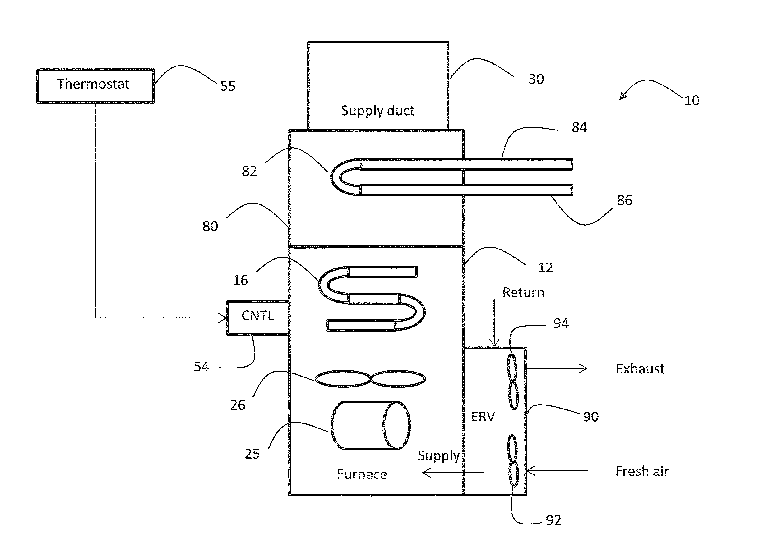
[0009] Referring to FIG. 1, numeral 10 generally designates an air conditioning unit having a furnace, an evaporator coil and an energy recovery ventilator (ERV). The ERV is described herein with reference to a gas furnace, but it is understood that the ERV (and control thereof) may be used with other systems, such as residential air handlers, and embodiments are not limited to a gas fired furnace as shown in FIG. 1. Air conditioning unit, as used herein, is intended to cover a variety of air handling equipment.
[0010] Air conditioning unit 10 includes a cabinet 12 housing therein furnace having a circulating air blower 26 driven by a blower motor 25. In heating mode, a heat exchanger 16 heats air circulated by air blower 26, which is supplied to a supply duct 30. A burner assembly, igniter, gas source, etc. are not shown for ease of illustration. An evaporator coil 82 is located in housing 80 on top of cabinet 12 and is the evaporator of a cooling unit. The evaporator coil 82 has an inlet 84, where subcooled refrigerant enters, and an outlet 86, where superheated refrigerant leaves, as is conventional. In cooling mode, evaporator coil 82 cools air circulated by air blower 26, which is supplied to a supply duct 30.
[0011] Cabinet 12 also houses a controller 54. Controller 54 may be implemented using a microprocessor-based controller executing computer program code stored on a computer readable storage medium. A thermostat 55 communicates with controller 54 to designate operational modes and temperature. Thermostat 55 may be an intelligent device that communicates requested air flow rates.
[0012] An energy recovery ventilator (ERV) 90 is mounted to a side of cabinet 12, but may be mounted in other locations. ERV 90 includes a fan 92 that draws fresh air from outside the building and uses energy from return air to precondition the outside air prior to distribution to cabinet 12. ERV 90 may be any existing type of ERV, such as a rotary heat exchanger (e.g., wheel) or plate heat exchanger with a membrane. ERV 90 may be arranged in cross-flow or counter-flow configuration. As used herein, ERV includes heat recovery ventilators (HRV), unless indicated otherwise.
[0013] Blower 26 is used to circulate supply air from ERV 90, through cabinet 12 and on to supply duct 30. Blower 26 also draws return air from location ducts back to the ERV 90 for energy recovery. ERV 90 includes an exhaust fan 94 for discharging exhaust air.
[0014] In embodiments of the invention, blower motor 25 is driven in a ventilation mode to reduce power consumption and still meet desired ventilation needs. In operation, thermostat 55 designates a mode such as low heat, high heat, low cool, high cool or ventilation. In ventilation mode, neither heating nor cooling is provided by air conditioning unit 10.
[0015] Control of blower motor 25 in ventilation mode may be accomplished in a variety of manners, depending on the type of blower motor 25. The goal is to reduce power to blower motor 25 while still meeting applicable ventilation requirements for the space being served.
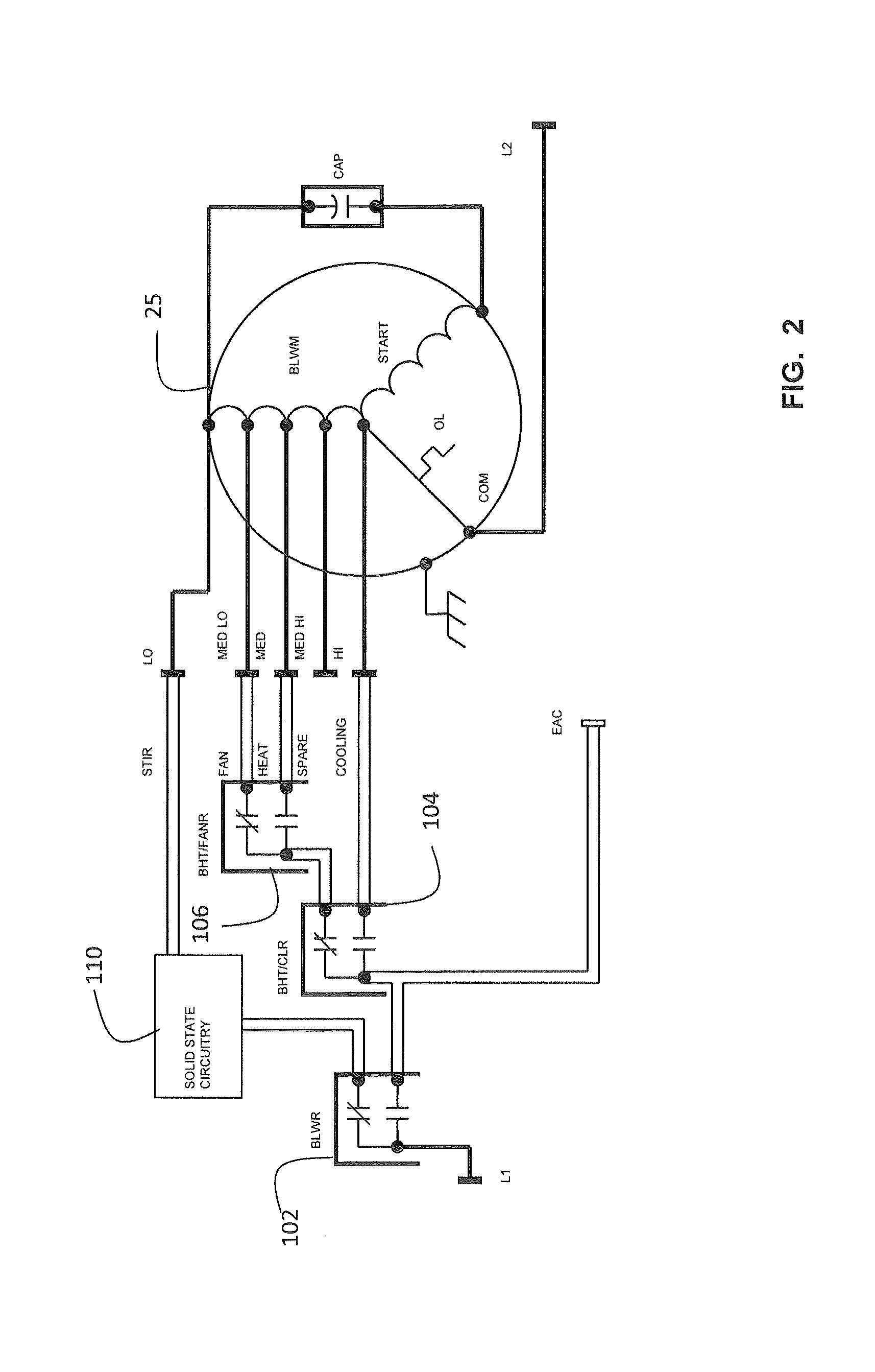
[0016] In exemplary embodiments, blower motor 25 is a permanent split capacitor (PSC) motor having multiple taps. The motor speed is controlled by applying an AC voltage (e.g., 115 VAC or 220 VAC) to a particular tap to achieve a desired motor speed. FIG. 2 illustrates an exemplary embodiment where blower motor 25 is a PSC motor having 5 taps, corresponding to fan speeds of low, medium-low, medium, medium-high and high.
[0017] AC voltage is applied at inputs L1 and L2 and relays 102, 104 and 106 are used to form a path from input L1 to one of the medium-low, medium, and high taps. The medium-high tap is not terminated as a spare. Relays 102, 104 and 106 have contacts rated as high as 20 amps.
[0018] The low tap is used in ventilation only mode (i.e., no heating or cooling demand) referred to in FIG. 2 as a stir cycle. In this ventilation mode, blower motor 25 operates at a lower speed, which results in power savings. A solid state switching device 110 is used to provide voltage to the low speed tap. Other types of switching devices (e.g., relays) may be used. Solid state switching device 110 may operate in response to commands from controller 54. Solid state switching device 110 may be activated when the system is operating in an idle state. Relay 102 connects input voltage L1 to solid state switching device 110. This diverts power from the electric air cleaner (EAC) that is typically run during heating and cooling modes.
[0019] Solid state switching device 110 may be triggered at zero crossing points of input voltage L1 to reduce in-rush current to blower motor 25. Logic in solid state switching device 110 implements the stir cycle when the blower is transitioning out of a heating, or cooling state.
[0020] FIG. 2 represents one exemplary blower motor 25. Embodiments of the invention may be used with other types of motors, such as discreet tap X13 motors. These motors are driven by, e.g., 24 VAC, and are supplied with 3 to 5 taps. These taps draw low current (less than 15 ma) and can also be driven with DC voltage. Existing systems switch these taps on and off with relays that have gold contacts for low current circuits. If blower motor 25 is a discreet tap X13 motor, a system of relays and solid state circuitry similar to FIG. 2 may be used to provide voltage to a low speed tap to run the motor 25 in the ventilation or stir mode, and reduce energy consumption.
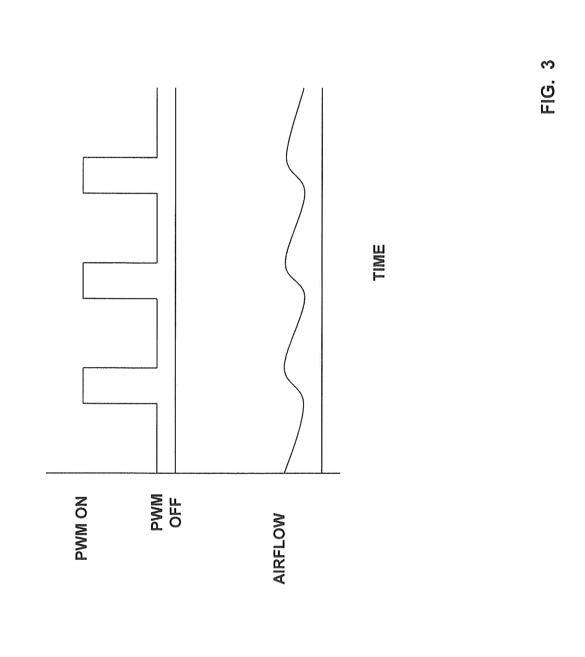
[0021] Another type of blower motor 25 that may be used in exemplary embodiments is a pulse width modulated (PWM) X-13 motor. These motors are driven with a PWM signal, which may be provided by controller 54. The PWM signal is, for example, between 80 hz and 120 hz, and causes the blower motor torque to vary with the percent duty cycle of the signal. Maximum motor torque will occur at 99% duty cycle and off will occur at a duty cycle of 0.4% or less. To activate the ventilation or stir mode, controller 54 generates an on PWM signal (having 1%-99% duty cycle) for a few seconds followed by an off PWM for a few seconds. FIG. 3 shows the on and off PWM signals, along with the airflow generated. It is understood that during the on PWM time, controller 54 is providing the PWM signal, made up of a series of pulses, to blower motor 25. During the off PWM time, no PWM signal is provided to blower motor 25. In exemplary embodiments, the on time may be 1 to 2 seconds and the off time may be 2 to 4 seconds OFF. The on PWM time and off PWM time may be dependent upon blower fan 26 inertia. By selectively applying the PWM signal, a lower motor RPM is achieved, meeting the airflow demands in ventilation mode and reducing energy consumption.
[0022] Another type of motor 25 that may be used in exemplary embodiments is a communicating electrically commutated motor (ECM) motor. In these embodiments, controller 54 controls blower motor 25 by transmitting digital communication commands. For example, a low motor RPM (e.g., just below 200 RPM) may be achieved by controller 54 sending a very low torque command, for example, 0-200. To achieve full motor torque, controller 54 sends a torque command of, for example, 65535. If the low torque command from controller 54 still results in too high of a motor RPM for the stir mode, then the torque command may be pulsed on and off, similar to the PWM on and off discussed above with reference to FIG. 3.
[0023] Driving the blower motor 25 to a low RPM in ventilation mode results in an energy savings when compared to existing units that drive the blower motor 25 at full speed during ventilation mode. Typical controls for ERV's and HRV's include timers for run time and wall controls to call for ventilation when needed. By ventilating continuously and employing the energy saving cycle, energy is saved and makes the timers and wall controls unnecessary. Cycling power to the blower during the ventilation mode at a prescribed rate also takes advantage of rotating blower inertia in order to stir the air sufficiently to deliver fresh air through the main air duct system to accomplish ventilation for the home but save on energy cost over running the main system blower solely for ventilation, especially with electronically commutated motors (ECM). The ventilation mode is also sufficient to prevent mixing of the supply and exhaust air streams from the ERV.
[0024] While the invention has been described in detail in connection with only a limited number of embodiments, it should be readily understood that the invention is not limited to such disclosed embodiments. Rather, the invention can be modified to incorporate any number of variations, alterations, substitutions or equivalent arrangements not heretofore described, but which are commensurate with the spirit and scope of the invention. Additionally, while various embodiments of the invention have been described, it is to be understood that aspects of the invention may include only some of the described embodiments. Accordingly, the invention is not to be seen as limited by the foregoing description, but is only limited by the scope of the appended claims.
* * * * *
D00000
D00001
D00002
D00003
XML
uspto.report is an independent third-party trademark research tool that is not affiliated, endorsed, or sponsored by the United States Patent and Trademark Office (USPTO) or any other governmental organization. The information provided by uspto.report is based on publicly available data at the time of writing and is intended for informational purposes only.
While we strive to provide accurate and up-to-date information, we do not guarantee the accuracy, completeness, reliability, or suitability of the information displayed on this site. The use of this site is at your own risk. Any reliance you place on such information is therefore strictly at your own risk.
All official trademark data, including owner information, should be verified by visiting the official USPTO website at www.uspto.gov. This site is not intended to replace professional legal advice and should not be used as a substitute for consulting with a legal professional who is knowledgeable about trademark law.