Coupling Device
COJOCARU; Victor ; et al.
U.S. patent application number 16/098196 was filed with the patent office on 2019-05-23 for coupling device. The applicant listed for this patent is EISELE PNEUMATICS GMBH & CO. KG. Invention is credited to Victor COJOCARU, Andreas NOTHDURFT.
| Application Number | 20190154180 16/098196 |
| Document ID | / |
| Family ID | 58461259 |
| Filed Date | 2019-05-23 |
| United States Patent Application | 20190154180 |
| Kind Code | A1 |
| COJOCARU; Victor ; et al. | May 23, 2019 |
COUPLING DEVICE
Abstract
The invention relates to a coupling device consisting of two connector block parts (2,4), which can be coupled to each other and which have a plurality of receptacles for connector parts (10), which connector parts are arranged in correspondence with each other and can be connected to each other, is characterized in that a supporting device is provided for supporting the coupling process, which supporting device has, on the one connector block part (2), a pivotable handle (16) having at least one guide slot (30), in which at least one guide part (32) of the other connector block part (4) engages in such a way that, when the handle (16) is pivoted, the guide slot (30) applies a force to the guide part (2, 4) in question in such a way that the connector block parts (2, 4) are moved toward each other for a coupling process.
| Inventors: | COJOCARU; Victor; (Stuttgart, DE) ; NOTHDURFT; Andreas; (Remshalden, DE) | ||||||||||
| Applicant: |
|
||||||||||
|---|---|---|---|---|---|---|---|---|---|---|---|
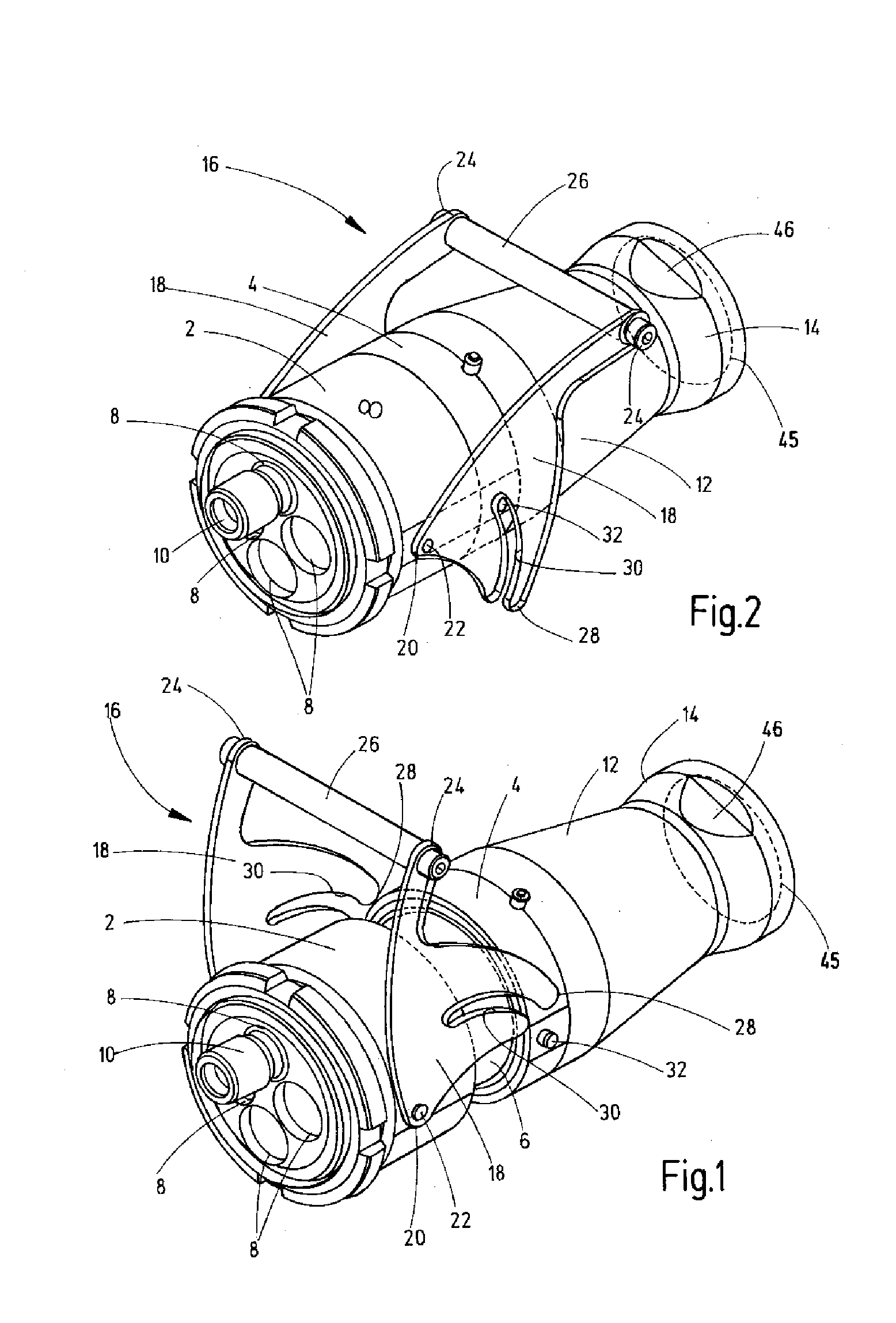
| Family ID: | 58461259 | ||||||||||
| Appl. No.: | 16/098196 | ||||||||||
| Filed: | March 29, 2017 | ||||||||||
| PCT Filed: | March 29, 2017 | ||||||||||
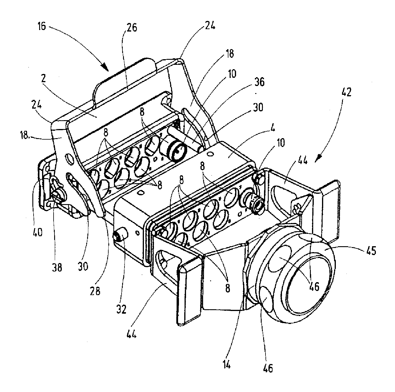
| PCT NO: | PCT/EP2017/000384 | ||||||||||
| 371 Date: | November 1, 2018 |
| Current U.S. Class: | 1/1 |
| Current CPC Class: | F16L 37/18 20130101; F16L 37/56 20130101 |
| International Class: | F16L 37/18 20060101 F16L037/18; F16L 37/56 20060101 F16L037/56 |
Foreign Application Data
| Date | Code | Application Number |
|---|---|---|
| May 2, 2016 | DE | 10 2016 005 303.8 |
Claims
1. A coupling device comprised of two connector block parts which can be coupled to each other (2, 4) with a plurality of receivers for connector parts (10), which connector parts are arranged corresponding with each other and can be connected to each other, characterized in that a facilitating device is provided for supporting the coupling process, having on the one connector block part (2) a pivotable handle (16) with at least one guide slot (30), a facilitating device is provided for supporting the coupling process, having a pivotable handle with at least one guide slot on the one connector block part, into which guide slot at least one guide part (32) of the other connector block part (4) engages such that when the handle (16) is pivoted the guide slot (30) applies a force to the guide part (2, 4) in question in such a way that the connector block parts (2, 4) are moved toward each other for a coupling process.
2. The coupling device according to claim 1, characterized in that the pivotable handle (16) encompasses the assignable connector block part in the manner of a bracket and has two side parts (18), that the side parts (18) of this connector block part, which are parallel and opposite each other are pivotably arranged on this connector block part (2) and that each side part (18) has a slot-like guide slot (30), which, running parallel to each other and penetrating the respective side part (18) in areas, are arranged therein.
3. The coupling device according to claim 1, characterized in that the respective guide part of the other connector block part (4) is formed by a guide pin (32) and that the two guide pins (32) are arranged in pairs and in the same engagement position at side walls of the other connector block part (4) arranged opposite such that they lie in the pivot path of the respective assignable guide slot (30) when the connector block parts (2, 4) approach each other toward their coupling position.
4. The coupling device according to claim 1, characterized in that the side parts (18) with the guide slot (30) are configured as a pivoting fork and connected to each other in pairs on one end (24) via a plate-like or rod-like grip part (26) and that the guide slot (30) between this end (24) and the end (20) of the respective side part (18) at which it is pivotably attached on the connector block part (2) opens outward for the accessing of the guide pin (32) by the other connector block part (4).
5. Coupling device according to claim 1, characterized in that the guide path of the guide slot (30) has a curved shape at least in the region of the opening and proceeding from it.
6. The coupling device according to claim 1, characterized in that at least on one pivot axis (38) on the one connector block part (2) the pivotable side part (18) remains positioned in a force-locking manner in every pivotal position by means of a pretensioning device, preferably in the form of at least one yoke spring (40).
7. The coupling device according to claim 1, characterized in that the respective connector block parts (2, 4) are configured in matching pairs as round bodies or as cuboids.
Description
[0001] The invention relates to a coupling device, comprised of two connector block parts which can be coupled to each other with a plurality of receivers for connector parts, which connector parts are arranged corresponding with each other and can be connected to each other.
[0002] Coupling devices of this type belong to the prior art and are known as multiple media couplings or multiple couplings. For example, DE 10 2009 030 936 A1 describes a coupling device of this type. These coupling devices can have a larger number of connector parts, which can be plugged together for connecting line sections. These lines can be for flowable media, like compressed air, or can be electrical lines. In principle, and in particular in the case of line sections under pressure, a secure mutual sealing of the connector parts by means of a sealant is essential in the coupling state. Above all, in the case of a greater number of connector parts a higher exertion of force can be required for carrying out the coupling process due to the friction on the sealants and because of the media pressure counteracting the connection.
[0003] With regard to this problem, the invention addresses the problem of providing a coupling device of the type specified in the introduction which facilitates a simple and comfortable implementation of the coupling process, even in the case of a greater number of connector parts.
[0004] According to the invention this problem is solved by a coupling device having the features of patent claim 1 in its entirety.
[0005] According to the characterizing part of claim 1, one essential special feature of the invention lies in the fact that a facilitating device is provided for facilitating the coupling process, having a pivotable handle with at least one guide slot on the one connector block part, into which guide slot at least one guide part of the other connector block part engages such that, when the handle is pivoted the guide slot applies a force to the guide part in question in such a way that the connector block parts are moved toward each other for a coupling process. In the case of an appropriately selected length of the lever arm formed on the handle between its manually graspable actuating end and the pivot point, a high force component acting in axial direction can be generated via the guide slot on the guide part engaging in it with a low amount of pivot torque to be applied to the handle by the operator, so that the coupling process can be implemented with a low exertion of force. Therefore, in contrast to the aforementioned solution of the prior art, in which, in an effort to reduce the exertion of force in the coupling process, the respective sealant of the connector parts is arranged in a specially configured receiving groove permitting an axial movement a sealing arrangement of random configuration can be used in the device of the invention.
[0006] In particularly advantageous exemplary embodiments the pivotable handle encompasses the assignable connector block part in the manner of a bracket and has two side parts, wherein the side parts of this connector block part, which are parallel and opposite each other, are pivotably arranged thereon and wherein each side part has a slot-like guide slot, which, running parallel to each other and penetrating the respective side part in areas, are arranged therein. In this bracket design the actuating part of the handle can be formed by a cross-member running between the two side parts, so that for the actuation a grip part formed by the cross-member with sufficient length in relation to the width of the bracket is available, which can be grasped particularly conveniently.
[0007] With particular advantage the respective guide part of the other connector block part can be formed by a guide pin, wherein two guide pins are arranged in pairs and in the same engagement position at side walls of the other connector block part arranged opposite such that they lie in the pivot path of the respective assignable guide slot when the connector block parts approach each other toward their coupling position. In the bracket design arranged such the risk of jamming when bringing the connector block parts together is avoided, because in the case of axial force generated simultaneously on opposing sides of the other connector block part the connector block parts are brought together without diagonal pull.
[0008] With particular advantage the assembly can be made such that the side parts with the guide slot are configured as a pivoting fork and connected to each other in pairs on one end via a plate-like or rod-like grip part, wherein the guide slot on the opposing end of the respective side part for receiving the guide pin of the other connector block part opens outward. In the process the guide path of the guide slot has a curved shape at least in the region of the opening and proceeding from it.
[0009] As a result, the pivoting movement of the side parts already leads to an axial force component on the guide pin at the start of the coupling process.
[0010] Advantageously the assembly can be made such that at least on one pivot axis on the one connector block part the pivotable side part remains positioned in a force-locking manner by means of a pretensioning device, preferably in the form of at least one yoke spring, in every pivotal position. As a result, loose pivoting movements of the side parts are prevented even in states without engagement of the guide pin in the respective guide slot.
[0011] The connector block parts, as is the case with the mentioned solution according DE 10 2009 030 936 A1 in the prior art, can be configured as round bodies or as cuboids in a type of box design.
[0012] The invention is explained in detail below on the basis of exemplary embodiments represented in the drawings.
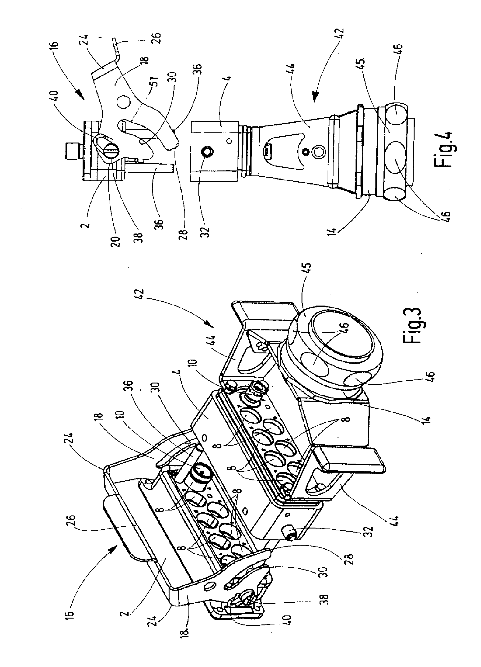
[0013] The figures show the following:
[0014] FIG. 1 shows a perspective diagonal view of an exemplary embodiment of the coupling device according to the invention, wherein the incompletely coupled state is shown;
[0015] FIG. 2 shows a perspective diagonal view of the exemplary embodiment of FIG. 1, wherein the completely coupled state is shown;
[0016] FIG. 3 shows a perspective diagonal view of a second exemplary embodiment of the coupling device according to the invention, wherein the connector block parts are shown in an exploded view; and
[0017] FIG. 4 shows the representation of FIG. 3 in lateral view.
[0018] With reference to FIGS. 1 and 2, the coupling device according to the invention is described in terms of an exemplary embodiment forming on the whole a round element. As in the aforementioned prior art (DE 10 2009 030 936 A1), the first connector block part 2, which is visible at the front in FIGS. 1 and 2, is designed in the manner of a coupling socket, into which a shell part 6 of the second connector block part 4, which is reduced in its external diameter, can be inserted when the device is transferred from the state shown in FIG. 1 to the coupled state shown in FIG. 2. Corresponding to the prior art, in the coupled state receivers are aligned perfectly to each other, which receivers are provided in connector block parts 2 and 4 for connector parts, which are affixed to the ends of line sections to be connected to each other.
[0019] In the illustrations of FIGS. 1 and 2 four receivers 8 are provided for connector parts 10, wherein in FIGS. 1 and 2 three of the receivers 8 have been left empty and only one inserted connector part 10 is visible, which is shown without an associated line section. In the coupling state the connector parts 10 of the one connector block part 2 have been brought together with the connector parts 10 of the second connector block part 4, wherein a sealant forms the seal between the connector parts 10. In the exemplary embodiment of FIGS. 1 and 2 the second connector block part 4 is extended by an attachment 12, which runs with slightly conical taper to a line guide part 14, which forms the exit for a relevant bundle of lines not shown in the figure.
[0020] A facilitating device, which facilitates the carrying out of the coupling process for the operator, has a handle designated as a whole by 16. Said handle is designed in the form of a pivot arm which has two identically configured side parts 18 in the form of sheet metal plates, which in each case with one end 20 one two opposing sides of the first connector block part 2 are pivotably mounted on a pivot pin 22 around a pivot axis. On the end 24 opposite the end 20 with the pivot pin 22, the side parts 18 are connected to each other by a round bar 26 forming a grip part. In the area between the ends 20 and 24 the side parts 18 have an extension 28 protruding towards the second connector block part 4, in which a slot 30 is formed, which forms a guide slot and which is open in the region of the end of the extension 28. The guide slots formed by the slot 30 of the side parts 18 serve as control elements for one guide pin 32 each, said control elements projecting on opposing sides of the second connector block part 4.
[0021] In the implementation of a coupling process the guide pins 32, proceeding from the state shown in FIG. 1, pivoting the handle 16 clockwise, enter into the slot 30 from its open end. For its function as a guide slot, the slot 30, proceeding from the opening, curved in the shape of a bow such that in the case of a progressing pivoting movement, in which the respective guide pin 32 moves along the slot 30, a force component develops on the guide pin 32 in axial direction, through which the connector block parts 2 and 4 are pulled against each other, so that the coupling device reaches the coupling state. In the case of the leverage ratio, as given by the distance between pivot pin 22 and end 24 of the side parts 18 and by the shape of the slots 30, which determine the pitch of the guide slot, in the case of a pivot actuation of the handle 16 which can be comfortably performed with low actuating force a high axial force results, resulting in a secure coupling process.
[0022] FIGS. 3 and 4 show a second exemplary embodiment. In contrast to the first described example, the first and second connector block parts 2 and 4 are not formed by round bodies, but rather in the manner of a box design in the form of cuboids, in which the receivers 8 for the respective connector parts 10 are located. As in the first example, of the existing receivers 8 only one receiver 8 is shown equipped with one connector part 10 in each case for each connector block part 2 and 4, wherein in the case shown in the figure it is connector parts 10 for electrical line sections, which are not shown in the figure. In bringing the connector block parts 2 and 4 together in the coupling process, one guide rod 36 each is provided on the first connector block part 2 near each short side of the rectangular shape, said guide rods engaging in (not visible in the figure) guide bores in the second connector block part 4 in the coupling process.
[0023] As in the first described example, the facilitating device facilitating the coupling process is in formed in a corresponding manner by a handle 16 in a bracket design with the side parts 18 configured the same as described in the first exemplary embodiment. Unlike the first exemplary embodiment, the grip part 26 connecting the ends 24 of the side parts 18 is formed not by a round bar, but rather by a cross-member in one piece with the side parts 18. As in the first example, a protruding guide pin 32 is provided for the interaction with the guide slots formed by the slot 30 of the side parts 18 on both sides of the second connector block part 4. As shown in particular in FIG. 4, the slot-like guide slot 30 has a recess or bulge 51 on the rear end protruding towards the grip part, which is to be bridged and locks the bracket in the form of the handle 16, so that in the coupled state it is secured against unintentional loosening without third party interference. The force is applied to seal 50 over the distance to be bridged.
[0024] For formation of the pivot axis for the side parts 18 the second exemplary embodiment, has a pivot bearing with a screw 38 in place of the pivot pin 22, with which a yoke spring 40 is held, which is in contact with the exterior of the relevant side part 18 under a pre-tensioning force. The handle 16 is secured in a force-locking manner against unwanted pivoting movements as a result, when the connector block parts 2 and 4 are not coupled and the handle 16 is therefore free. In the second exemplary embodiment, a guide bracket 42 is provided as the guide for a bundle of lines going away from the second connector block part 4, said bundle of lines which is not shown in the figure, in place of the attachment 12 provided in the first exemplary embodiment with exit guide part 14. Said guide bracket has two lateral flanges 44, which are screwed into the second connector block part 4. The exit guide part 14 is located at the end of the flanges 44, just as it is also arranged at the end of the attachment 12 of the second connector block part 4 in the first exemplary embodiment. As in the first exemplary embodiment, the guide part 14 has flat sections 46 on an external threaded ring 45, said flat sections forming the points of application for turning the threaded ring 45.
* * * * *
D00000
D00001
D00002
XML
uspto.report is an independent third-party trademark research tool that is not affiliated, endorsed, or sponsored by the United States Patent and Trademark Office (USPTO) or any other governmental organization. The information provided by uspto.report is based on publicly available data at the time of writing and is intended for informational purposes only.
While we strive to provide accurate and up-to-date information, we do not guarantee the accuracy, completeness, reliability, or suitability of the information displayed on this site. The use of this site is at your own risk. Any reliance you place on such information is therefore strictly at your own risk.
All official trademark data, including owner information, should be verified by visiting the official USPTO website at www.uspto.gov. This site is not intended to replace professional legal advice and should not be used as a substitute for consulting with a legal professional who is knowledgeable about trademark law.