Vacuum Suction Unit
LEE; Jeongho ; et al.
U.S. patent application number 16/250937 was filed with the patent office on 2019-05-23 for vacuum suction unit. The applicant listed for this patent is LG ELECTRONICS INC.. Invention is credited to Younggyu JUNG, Taekyung KIM, Changgun LEE, Jeongho LEE, Sangchul LEE.
| Application Number | 20190154057 16/250937 |
| Document ID | / |
| Family ID | 55650183 |
| Filed Date | 2019-05-23 |


| United States Patent Application | 20190154057 |
| Kind Code | A1 |
| LEE; Jeongho ; et al. | May 23, 2019 |
Vacuum Suction Unit
Abstract
A vacuum suction unit is provided. The vacuum suction unit includes a cover, an impeller, a motor, a guide device which includes a guide body and a guide vane, a flow guide which is disposed below the guide device and guides the air guided by the guide device toward the stator, and a motor housing which accommodates the motor and includes an air outlet. Here, a guide surface at least a part of which has a diameter reduced as getting downward is formed at a bottom surface of the flow guide, the guide vane includes a first guide vane which is provided on a side of the guide body and guides the air ejected from the impeller, and an inlet angle of the first guide vane is within a range from 10 to 25 degrees.
| Inventors: | LEE; Jeongho; (Seoul, KR) ; LEE; Changgun; (Seoul, KR) ; LEE; Sangchul; (Seoul, KR) ; KIM; Taekyung; (Seoul, KR) ; JUNG; Younggyu; (Seoul, KR) | ||||||||||
| Applicant: |
|
||||||||||
|---|---|---|---|---|---|---|---|---|---|---|---|
| Family ID: | 55650183 | ||||||||||
| Appl. No.: | 16/250937 | ||||||||||
| Filed: | January 17, 2019 |
Related U.S. Patent Documents
| Application Number | Filing Date | Patent Number | ||
|---|---|---|---|---|
| 15088582 | Apr 1, 2016 | |||
| 16250937 | ||||
| Current U.S. Class: | 1/1 |
| Current CPC Class: | F04D 25/06 20130101; F04D 29/4206 20130101; F04D 29/28 20130101; F04D 29/444 20130101; F04D 29/441 20130101; F04D 29/056 20130101; F04D 29/053 20130101 |
| International Class: | F04D 29/44 20060101 F04D029/44; F04D 29/42 20060101 F04D029/42; F04D 25/06 20060101 F04D025/06; F04D 29/056 20060101 F04D029/056; F04D 29/053 20060101 F04D029/053; F04D 29/28 20060101 F04D029/28 |
Foreign Application Data
| Date | Code | Application Number |
|---|---|---|
| Apr 1, 2015 | KR | 10-2015-0045951 |
| Apr 6, 2015 | KR | 10-2015-0048234 |
Claims
1. A vacuum suction unit comprising: a cover including an air inlet; an impeller for moving air which flows in through the air inlet; a motor including a stator and a shaft which is connected to the impeller and rotates with respect to the stator; a guide device including a guide body disposed below the impeller and a guide vane provided at the guide body to guide air ejected from an outlet of the impeller; a flow guide disposed below the guide device and guides the air guided by the guide device toward the stator; and a motor housing accommodating the motor and comprises an air outlet, wherein a first flow path is defined between an inner circumferential surface of the cover and the guide body, the first flow path becoming narrower as the first flow path approaches a top end portion of the guide vane from the outlet of the impeller, wherein the guide vane comprises a first guide vane which is provided on a side of the guide body and guides the air ejected from the impeller, and wherein an inlet angle of the first guide vane is within a range from 10 to 25 degrees.
2. The vacuum suction unit of claim 1, wherein the guide vane further comprises a second guide vane which is provided at a bottom surface of the guide body, is connected to the first guide vane, and guides the air guided by the first guide vane.
3. The vacuum suction unit of claim 1, wherein the guide surface is formed rounded toward the shaft.
4. The vacuum suction unit of claim 1, wherein an angle of inclination of the guide surface is from 10 to 30 degrees.
5. The vacuum suction unit of claim 1, wherein an inner circumferential surface of the cover is formed in a shape which inclines at a certain angle with respect to a top surface of the guide body.
6. The vacuum suction unit of claim 1, wherein a first flow path is formed between an inner circumferential surface of the cover and the guide body, and the first flow path becomes narrower as getting from the outlet of the impeller closer to a top end portion of the guide vane.
7. The vacuum suction unit of claim 6, further comprising a motor bracket disposed below the guide device and coupled with the cover, wherein a second flow path connected to the first flow path is formed between an inner circumferential surface of the motor bracket and the guide body.
8. The vacuum suction unit of claim 7, wherein the cover comprises a first coupling portion coupled with the motor bracket, and the motor bracket comprises a bracket body for forming the second flow path and a second coupling portion provided outside the bracket body and connected with the first coupling portion.
9. The vacuum suction unit of claim 8, wherein a bottom surface of the first coupling portion is located lower than the top end portion of the guide vane.
10. The vacuum suction unit of claim 7, wherein the flow guide is detachably coupled with the motor bracket, and the flow guide comprises a coupling portion connected to the motor bracket.
11. The vacuum suction unit of claim 1, wherein the guide body including a rim portion provided on an outer circumference, and wherein the rim portion provided outside the impeller.
12. The vacuum suction unit of claim 11, wherein a plane is formed on a top surface portion of the rim portion, and an inner circumferential surface of the cover may incline with respect to a top surface portion of the rim portion at a predetermined angle, and wherein the first flow path may become narrower in a direction the air moves.
13. The vacuum suction unit of claim 1, wherein the flow guide defines a guide surface at a lower side of the flow guide, at least a part of the guide surface having a diameter that decreases as the guide surface approaches the motor.
Description
CROSS-REFERENCE TO RELATED APPLICATIONS
[0001] This application is a continuation of U.S. application Ser. No. 15/088,582, filed Apr. 1, 2016, which claims priority under 35 U.S.C. .sctn. 119 and 35 U.S.C. .sctn. 365 to Korean Patent Application No. 10-2015-0048234, filed in Korea on Apr. 6, 2015, and Korean Patent Application No. 10-215-0045951, filed in Korea on Apr. 1, 2015, whose entire disclosure is hereby incorporated by reference.
BACKGROUND
[0002] A vacuum suction unit may be generally included in an electric cleaner and used to suction in air including dust.
[0003] Korean Patent Publication No. 2013-0091841 (Aug. 20, 2013) which is a prior document discloses a vacuum suction unit.
[0004] The vacuum suction unit includes a motor, an impeller connected to a motor by a rotating shaft and suctioning in air by rotating, a guide member adjacently disposed to the impeller and guiding air ejected by the impeller, and a cover which covers the impeller and the guide member.
[0005] The guide member includes a body portion disposed below the impeller and a guide vane which is formed on a side of the body portion and guides the air ejected by the impeller. An air flow path through which air flows is formed between the cover and the body portion. The air which flows into inside the cover due to the impeller passes through the air flow path and moves toward the guide vane.
[0006] The vacuum suction unit of the prior document has a large flow loss during a process in which the air ejected by the impeller is guided by the guide vane.
[0007] Also, a vortex may occur during a process in which the air which flows in due to the impeller flows through the air flow path, thereby generating a flow loss.
SUMMARY
[0008] An aspect of the present invention provides a vacuum suction unit which minimizes a flow loss by optimizing an inlet angle of a guide vane and an angle of inclination of a flow guide.
[0009] Another aspect of the present invention provides a vacuum suction unit which reduces a flow loss by optimizing a shape of an air flow path.
[0010] According to one aspect of the present invention, a vacuum suction unit includes a cover which includes an air inlet, an impeller for moving air which flows in through the air inlet, a motor which includes a stator and a shaft which is connected to the impeller and rotates with respect to the stator, a guide device which includes a guide body disposed below the impeller and a guide vane provided at the guide body to guide air ejected from an outlet of the impeller, a flow guide which is disposed below the guide device and guides the air guided by the guide device toward the stator, and a motor housing which accommodates the motor and includes an air outlet. Here, a guide surface at least a part of which has a diameter reduced as getting downward is formed at a bottom surface of the flow guide, the guide vane includes a first guide vane which is provided on a side of the guide body and guides the air ejected from the impeller, and an inlet angle of the first guide vane is within a range from 10 to 25 degrees.
BRIEF DESCRIPTION OF THE DRAWINGS
[0011] Embodiments will be described in detail with reference to the following drawings in which like reference numerals refer to like elements, and wherein:
[0012] FIG. 1 is a front view of a vacuum suction unit according to one embodiment of the present invention;
[0013] FIG. 2 is an exploded perspective view of the vacuum suction unit of FIG. 1;
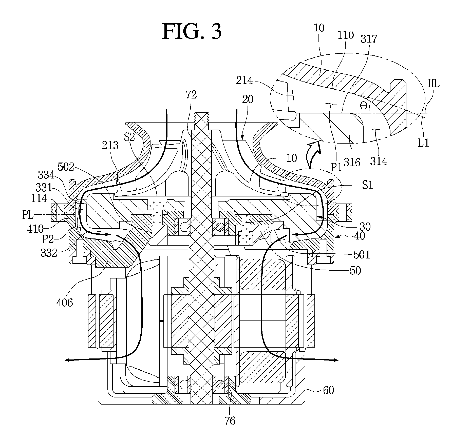
[0014] FIG. 3 is a longitudinal cross-sectional view of the vacuum suction unit of FIG. 1;
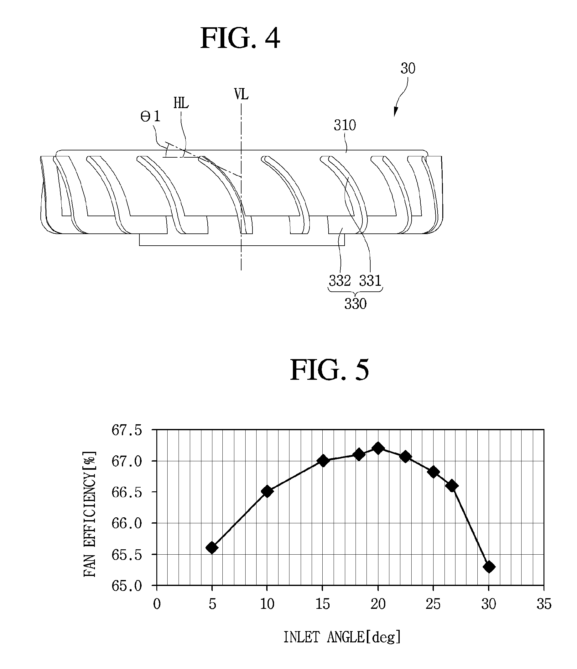
[0015] FIG. 4 is a view of a guide vane according to one embodiment of the present invention;
[0016] FIG. 5 is a graph illustrating efficiency depending on an inlet angle of a guide vane;
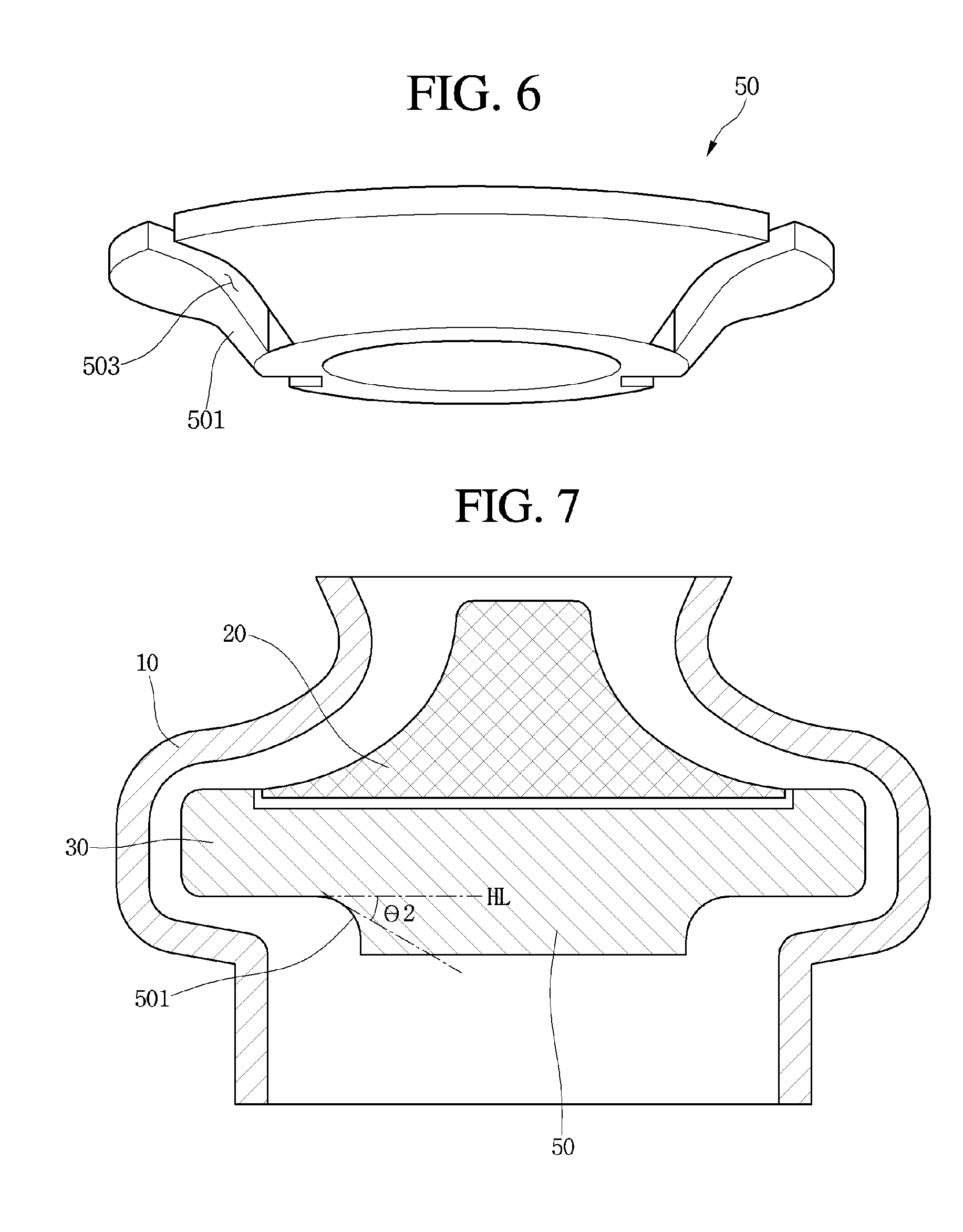
[0017] FIG. 6 is a bottom view of a flow guide shown in FIG. 2;
[0018] FIG. 7 is a view illustrating an angle between the flow guide and a horizontal line;
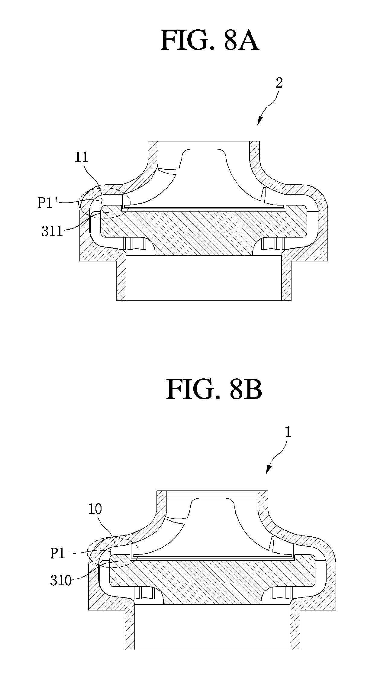
[0019] FIG. 8(a) is a cross-sectional view of a conventional vacuum suction unit;
[0020] FIG. 8(b) is a cross-sectional view of the vacuum suction unit according to one embodiment of the present invention;
[0021] FIG. 9(a) illustrates an airflow of the conventional vacuum suction unit;
[0022] FIG. 9(b) illustrates an airflow of the vacuum suction unit according to one embodiment of the present invention; and
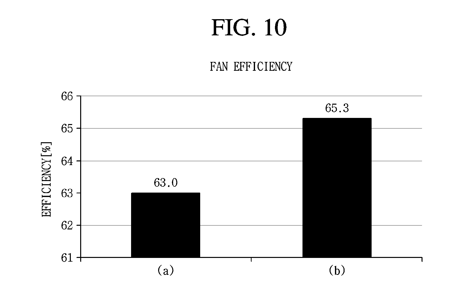
[0023] FIG. 10 illustrates graphs about efficiency of the conventional vacuum suction unit shown in FIG. 8(a) and the vacuum suction unit according to one embodiment of the present invention shown in FIG. 8(b).
DETAILED DESCRIPTION
[0024] FIG. 1 is a front view of a vacuum suction unit according to one embodiment of the present invention. FIG. 2 is an exploded perspective view of the vacuum suction unit of FIG. 1. FIG. 3 is a longitudinal cross-sectional view of the vacuum suction unit of FIG. 1.
[0025] Referring to FIGS. 1 to 3, a vacuum suction unit 1 according to one embodiment of the present invention may include a cover 10 which includes an air inlet 102 and a motor housing 60 which includes one or more air outlets 602.
[0026] The cover 10 may guide air which flows in through the air inlet 102 toward an impeller 20. Also, the cover 10 may maintain a vacuum pressure by insulating inner space from outside air pressure.
[0027] The vacuum suction unit 1 further includes the impeller 20 accommodated in the cover 10.
[0028] The impeller 20 increases static pressure energy and dynamic pressure energy of the air which flows in through the air inlet 102. Accordingly, a flow rate of the air may be increased by the impeller 20.
[0029] The impeller 20, for example, may include a hub 210 and a plurality of impeller blades 212 arranged in the hub 210.
[0030] Each of the impeller blades 212 may extend from a top end 213a to a bottom end 213b and may be formed in a three-dimensional shape. The air which flows may be moved to spaces between each of the adjacent impeller blades 212. Accordingly, spaces between the bottom ends 213b of the plurality of impeller blades 212 may be referred to as impeller outlets 214.
[0031] The air which flows in through the air inlet 102 may flow in through a top end of each of the impeller blades 212 and may be radially guided toward the bottom end 213b of each of the impeller blades 212.
[0032] The vacuum suction unit 1 may further include a guide device 30 which guides a flow of the air discharged through the impeller outlet 214.
[0033] The guide device 30 converts the dynamic pressure energy of the energy components of the air discharged through the impeller outlet 214 into the static pressure energy. That is, the guide device 30 may increase static pressure energy by reducing a flow rate of a fluid.
[0034] At least a part of the guide device 30 may be located in the cover 10, and the impeller 20 may be located above the guide device 30.
[0035] The guide device 30 may include a guide body 310 and a plurality of guide vanes 330 arranged around the guide body 310.
[0036] For example, the guide body 310 may be formed in a cylindrical shape, and the plurality of guide vanes 330 may be arranged along a circumferential direction of the guide body 310 with each spaced apart.
[0037] The guide vanes 330 may include a first guide vane 331 provided on a side of the guide body 310 and a second guide vane 332 which extends from the first guide vane 331 and is provided at a bottom surface of the guide body 310.
[0038] The first guide vane 331 may vertically extend, and the second guide vane 332 may horizontally extend. The second guide vane 332 is disposed on the bottom surface of the guide body 310, thereby increasing a length over which the flow of the air is guided.
[0039] The first guide vane 331 may be located over a first flow path P1 and a second flow path P2 which will be described below. The second guide vane 332 may be located at the second flow path P2.
[0040] The vacuum suction unit 1 may further include a motor bracket 40 to be coupled with the cover 10.
[0041] The motor bracket 40 may include a bracket body 402, a supporter 404 disposed in an inner portion of the bracket body 402, and a connection portion 406 which connects the bracket body 402 with the supporter 404.
[0042] The motor bracket 40 may be disposed between the cover 10 and the motor housing 60 and may be fastened to each of the cover 10 and the motor housing 60. For example, the motor bracket 40 may be fastened to a bottom of the cover 10, and the motor housing 60 may be coupled with a bottom of the motor bracket 40.
[0043] The cover 10 may include a first coupling portion 114 to be connected with the motor bracket 40. The first coupling portion 114, as shown in the drawing, may be formed in an annular shape.
[0044] The motor bracket 40 may include a second coupling portion 410 to be connected with the first coupling portion 114. The second coupling portion 410 may be provided outside the bracket body 402.
[0045] A bottom surface of the first coupling portion 114 is in contact with a top surface of the second coupling portion 410. A plane which is formed by connecting points where the bottom surface of the first coupling portion 114 meets the top surface of the second coupling portion 410 is referred to as a parting line PL. Since the parting line PL is a place where the cover 10 and the motor bracket 40 are connected and an air leak may occur, the bottom surface of the first coupling portion 114 and the top surface of the second coupling portion 410 are formed in shapes corresponding to each other.
[0046] One part of the motor bracket 40 may be located on sides of the plurality of guide vanes 330, and another part thereof may be located below the plurality of guide vanes 330.
[0047] The parting line PL is disposed lower than top end portions 334 of each of the guide vanes 330.
[0048] Accordingly, the air which flows through the first flow path P1 arrives at inlets of the plurality of guide vanes 330 and is guided before arriving at the parting line PL.
[0049] A position of the parting line PL is disposed below the inlets 314 of the plurality of guide vanes 330 as described above, thereby reducing a flow loss of the air.
[0050] The supporter 404 may support the guide device 30. In detail, the guide body 310 may be mounted on the supporter 404. A part of the supporter 404 may be accommodated in the guide body 310.
[0051] To prevent the supporter 404 from acting as a resistance to the air guided by the second guide vane 332, the supporter 404 may be located higher than a bottom surface of the second guide vane 332.
[0052] With the guide body 310 mounted on the supporter 404, an outer side of the guide body 310 may be spaced apart from an inner side of the cover 10. Accordingly, the first flow path P1 for allowing the air to flow may be formed between the outer side of the guide body 310 and the inner side of the cover 10.
[0053] With the guide body 310 mounted on the supporter 404, the outer side of the guide body 310 may be spaced apart from the bracket body 402. Accordingly, the second flow path P2 for allowing the air to flow may be formed between the outer side of the guide body 310 and the bracket body 402.
[0054] The second flow path P2 is connected with the first flow path P1. A boundary between the first flow path P1 and the second flow path P2 corresponds to a virtual plane formed by connecting points where the bracket body 402 and the cover 10 meet.
[0055] At least a part of the guide body 310 may be disposed between the supporter 404 and the bracket body 402 while mounted on the supporter 404. That is, at least a part of the guide device 30 may be accommodated in the motor bracket 40.
[0056] The guide body 310 may further include a rim portion 316 provided on an outer circumference.
[0057] The rim portion 316 may be provided outside the impeller 20. Accordingly, the air discharged through the impeller outlet 214 of the impeller 20 flows toward a top of the rim portion 316.
[0058] An inner circumferential surface 110 of the cover 10 may incline with respect to a top surface portion 317 of the rim portion 316 at a predetermined angle .theta.. The predetermined angle .theta. means an angle formed by an extension line L1 of the inner circumferential surface 110 of the cover 10 and a horizontal line HL.
[0059] The first flow path P1 may become narrower toward the top end portion 334 of the guide vane 330. In other words, the first flow path P1 may become narrower in a direction the air moves.
[0060] Also, a shape of the inner circumferential surface 110 of the cover 10 may be streamlined as shown in the drawing. This is to minimize air resistance and to prevent a vortex of air. Accordingly, the flow loss of the air which flows through the first flow path P1 may be reduced.
[0061] The plurality of guide vanes 330 may be located over the first flow path P1 and the second flow path P2 and may guide the flow of air.
[0062] One or more of the plurality of guide vanes 330 may be in contact with the bracket body 402 while the guide body 310 is mounted on the supporter 404.
[0063] The vacuum suction unit 1 may further include a motor for rotating the impeller 20.
[0064] The motor may be accommodated in the motor housing 60. Accordingly, the motor may be located below the supporter 404.
[0065] The motor may include a stator 80, a rotor which rotates with respect to the stator 80, and a shaft 72 connected to the rotor 70.
[0066] The stator 80 may include a coil 802. Although not limiting, the rotor 70 may be located inside the stator 80. The rotor 70 may include a permanent magnet.
[0067] One or more bearings 74 and 76 may be coupled with the shaft 72. The one or more bearings 74 and 76 may include an upper bearing 74 and a lower bearing 76. The upper bearing 74 may be located at an upper portion of the rotor 70, and the lower bearing 74 may be located at a lower portion of the rotor 70.
[0068] The upper bearing 74 may be supported by the supporter 404 of the motor bracket 40. For example, at least a part of the upper bearing 74 may be accommodated in the supporter 404. Although not limiting, the upper bearing 74 may be inserted into the supporter 404 from a bottom portion of the supporter 404.
[0069] The motor housing 60 may support the lower bearing 76.
[0070] The vacuum suction unit 1 may further include a flow guide 50 which guides the air guided by the guide vane 330 toward the stator 80.
[0071] The flow guide 50 may be fastened to the supporter 404 of the motor bracket 40 by a first fastening member S1. Also, the guide device 30 may be fastened to the supporter 404 by a second fastening member S2.
[0072] At least a part of the supporter 404 may be inserted into the flow guide 50.
[0073] To prevent interference in the connection portion 406, the flow guide 50 may include an opening 502 through which the connection portion 406 passes.
[0074] The shaft 72 may pass through the motor bracket 40 and the guide device 30 and may be coupled with the impeller 20. For example, the shaft 72 may pass through the supporter 404 and the guide body 310.
[0075] The airflow in the vacuum suction unit 1 will be briefly described below.
[0076] When power is applied to the vacuum suction unit 1, the motor is driven. Then, the rotor 70 rotates from the stator 80, and the shaft 72 coupled with the rotor 70 is rotated. When the shaft 72 is rotated, the impeller 20 connected to the shaft 72 is rotated.
[0077] Due to the impeller 20, air outside the vacuum suction unit 1 flows into the cover 10 through the air inlet 102. The air which flows into the cover 10 moves along the impeller 20.
[0078] The air discharged through the impeller outlet 214 is guided by the cover 10 to flow toward the guide vane 330 of the guide device 30. After that, the air flows along the first flow path P1 and the second flow path P2 during which the guide vane 330 guides the flow of the air.
[0079] The flow direction of air which passes through the second flow path P2 is changed by the flow guide 50 and flows downward. A part of the air which passes through the second flow path P2 may not pass through the motor and may be discharged through some of a plurality of such air outlets 602 in the motor housing 60, and another part may pass through the motor and then may be discharged through other of the plurality of air outlets 602 of the motor housing 60.
[0080] FIG. 4 is a view of the guide vane according to one embodiment of the present invention. FIG. 5 is a graph illustrating efficiency according to an inlet angle of a guide vane.
[0081] Referring to FIGS. 4 and 5, an inlet angle .theta.1 of the guide vane 330 means an angle formed by an extension line extending in the direction of a part of the guide vane 330, where air discharged through the impeller outlet 214 makes a first contact, and the horizontal line HL.
[0082] In the embodiment, the inlet angle of the guide vane 330 may be formed smaller than 90 degrees. That is, at least a part of the guide vane 330 may be disposed to incline at a certain angle based on the vertical line VL (which is an extension line extending in a direction parallel to an extension direction of a shaft).
[0083] Referring to FIG. 5, it may be confirmed that fan efficiency is 66.5% or more when the inlet angle of the guide vane 330 is within a range from 10 to 27 degrees. Also, the fan efficiency is maximized to be 67% or more when the inlet angle of the guide vane 330 is 20 degrees. The fan efficiency may be reduced when the inlet angle of the guide vane 330 is less than 20 degrees or more than 20 degrees.
[0084] When the inlet angle of the guide vane 330 is less than 10 degrees, the fan efficiency drops to be 66% or less. Also in this case, it is undesirable because the guide vane 330 acts as flow resistance and increases a flow loss of the air.
[0085] When the inlet angle of the guide vane 330 is more than 27 degrees, the fan efficiency drops to be 66% or less. In this case, the guide vane 330 is substantially incapable of guiding and then the flow loss becomes large.
[0086] Accordingly, in the embodiment, the inlet of the guide vane 330 may be selected within the range from 10 to 27 degrees.
[0087] In the case of the prior document described above, an inlet angle of a first guide vane is about 40 degrees. In the embodiment, the fan efficiency notably increases compared with the prior document.
[0088] A part of the second guide vane 332 may be located outside the second flow path P2. Accordingly, the air which passes through the second flow path P2 may be guided by the second guide vane 332.
[0089] Also, at least a part of the second guide vane 332 may increase in a vertical length as getting closer to the shaft 72. In this case, an air guide area increases in the second guide vane 332 in such a way that the air may smoothly flow toward the flow guide 50.
[0090] For example, at least a part of the second guide vane 332 located in the second flow path P2 may increase in a vertical length as getting closer to the shaft 72. Also, at least a part of the second guide vane 332 located outside the second flow path P2 may increase in a vertical length as getting closer to the shaft 72.
[0091] At least a part of the second guide vane 332 may be located at the same height as that of at least a part of a guide surface 501 of the flow guide 50.
[0092] In the embodiment, at least a part of the first guide vane 331 may be disposed to incline with respect to the vertical line VL, and an inlet angle of the first guide vane 331 may be selected within a range from 10 to 27 degrees.
[0093] According to the embodiment, at least a part of the guide vane may be disposed to incline with respect to the vertical line VL, and, by selecting the inlet angle of the guide vane to be within the range of 10 to 27 degrees, there is an advantage of a reduced flow loss of air and increased fan efficiency.
[0094] FIG. 6 is a bottom view of the flow guide shown in FIG. 2. FIG. 7 is a view illustrating an angle between the flow guide and a horizontal line.
[0095] Referring to FIGS. 3, 6, and 7, the flow guide 50 may include the guide surface 501 for guiding an airflow.
[0096] The guide surface 501 may be provided on a bottom surface of the flow guide 50, and at least a part of the flow guide 50 may be formed in a shape with a diameter which is reduced as getting closer to a bottom.
[0097] The guide surface 501 may be formed of a rounded or inclined shape. In detail, at least a part of the guide surface 501 may be formed in a curved shape curved toward the shaft 72 or may be formed with an incline at a certain angle with respect to the horizontal line HL.
[0098] An angle .theta.2 of the guide surface 501 may mean an angle formed by a tangent at a place of the guide surface 501 where air discharged from the guide vane 330 makes a first contact and the horizontal line HL.
[0099] The angle .theta.2 of the guide surface 501 may be smaller than 90 degrees. For example, a range of the angle .theta.2 of the guide surface 501 may be from about 10 to about 30 degrees.
[0100] As the angle .theta.2 of the guide surface 501 increases, fan efficiency may be increased.
[0101] However, when the inlet angle .theta.1 of the guide vane 330 is relatively large, the fan efficiency may be reduced instead as the angle .theta.2 of the guide surface 501 increases.
[0102] For example, when the inlet angle .theta.1 of the guide vane 330 is 30 degrees, the fan efficiency when the angle .theta.2 of the guide surface 501 is 0 degrees is higher than the fan efficiency when the angle .theta.2 of he guide surface 501 is 30 degrees.
[0103] Meanwhile, when the inlet angle .theta.1 of the guide vane 330 is 25 degrees, the fan efficiency when the angle .theta.2 of the guide surface 501 is 30 degrees is similar to the fan efficiency when the angle .theta.2 of he guide surface 501 is 0 degrees. That is, when the inlet angle .theta.1 of the guide vane 330 is 25 degrees, an effect of an angle of the guide surface 501 on fan efficiency may be slight.
[0104] When the inlet angle .theta.1 of the guide vane 330 is 25 degrees or more, fan efficiency may be even more increased when the guide surface 501 is formed without an incline.
[0105] Accordingly, when the guide surface 501 has an angle, the inlet angle .theta.1 of the guide vane 330 may preferably be 25 degrees or less.
[0106] When the inlet angle .theta.1 of the guide vane 330 is 20 degrees and the angle .theta.2 of the guide surface 501 is 30 degrees, the fan efficiency may be maximized.
[0107] The air guided by the guide vane 330 may be guided toward the stator 80 by the guide surface 501.
[0108] The flow guide 50 may prevent the air whose flow is guided by the guide vane 330 from flowing toward the shaft 72. That is, the flow guide 50 may guide the air not to flow in a horizontal direction that is perpendicular to the extension direction of the shaft 72 and to flow downward by changing a flow direction of the air.
[0109] The flow guide 50 may further include a coupling portion 503 provided at the guide surface 501 and coupled with the motor bracket 40.
[0110] The coupling portion 503 may be formed as a recess in the guide surface 501. The connection portion 406 may be inserted into the coupling portion 503, and the coupling portion 503 may be formed in the same number as that of the connection portions 406.
[0111] Accordingly, the flow guide 50 may be detachably mounted on the motor bracket 40. Accordingly, it is easy to replace the flow guide 50 and easy to change an angle of inclination of the guide surface 501.
[0112] According to the embodiment, by selecting the angle .theta.2 formed by the guide surface 501 provided at the flow guide 50 and the horizontal line to be within a range from 0 to 30 degrees, there is an advantage of a minimized flow loss of air and increased fan efficiency.
[0113] Hereinafter, efficiency due to different shapes of the vacuum suction unit 1 and a conventional vacuum suction unit will be compared.
[0114] FIG. 8(a) is a cross-sectional view of a conventional vacuum suction unit, and FIG. 8(b) is a cross-sectional view of the vacuum suction unit according to one embodiment of the present invention. FIG. 9(a) illustrates an airflow of the conventional vacuum suction unit, and FIG. 9(b) illustrates an airflow of the vacuum suction unit according to one embodiment of the present invention. A graph (a) illustrated in FIG. 10 illustrates efficiency of the conventional vacuum suction unit shown in FIG. 8(a), and A graph (b) illustrated in FIG. 10 illustrates efficiency of the vacuum suction unit according to one embodiment of the present invention shown in FIG. 8(b).
[0115] In detail, FIG. 8(a) is a cross-sectional view of a conventional vacuum suction unit, and FIG. 8(b) is a cross-sectional view of the vacuum suction unit according to one embodiment of the present invention. FIG. 9(a) illustrates an airflow of the conventional vacuum suction unit, and FIG. 9(b) illustrates an airflow of the vacuum suction unit according to one embodiment of the present invention. FIG. 10(a) illustrates efficiency of the conventional vacuum suction unit, and FIG. 10(b) illustrates efficiency of the vacuum suction unit according to one embodiment of the present invention.
[0116] Referring to FIGS. 8(a) to 10, as described above, in the vacuum suction unit 1 according to one embodiment of the present invention, the first flow path P1 formed between the cover 10 and the guide body 310 becomes narrower as getting closer to the guide vane 330.
[0117] On the contrary, in a conventional vacuum suction unit 2, a flow path P1' formed between the cover 11 and the guide body 311 has a uniform width. That is, an inner circumferential surface of the cover 11 of the conventional vacuum suction unit 2 does not incline and extends in a horizontal direction.
[0118] Accordingly, a vortex of air occurs at an edge 111 of the inner circumferential surface of the cover 11 of the conventional vacuum suction unit 2, thereby decreasing efficiency.
[0119] Referring to FIG. 10, it may be ascertained that the vacuum suction unit 1 according to one embodiment of the present invention has a fan efficiency of 65.3%, and the conventional vacuum suction unit 2 has fan efficiency of 63.0%.
[0120] As described above, a decrease in efficiency may be prevented by forming a streamlined shape of an inner circumferential surface of the cover 10.
[0121] According to one embodiment of the present invention, selecting an inlet angle of a first guide vane disposed on a side of a guide body to be within a range from 10 to 25 degrees and selecting an angle of inclination of a guide surface of a flow guide to be within a range from 10 to 30 degrees, there is an advantage of minimizing a flow loss of air and maximizing fan efficiency.
[0122] Also, by detachably attaching the flow guide to a motor bracket, there is an advantage where the flow guide is replaceable and the angle of inclination of the guide surface of the flow guide is easily changeable.
[0123] Also, due to the shape of an inner circumferential surface of a cover of a vacuum suction unit being streamlined, there is an advantage of minimizing the flow loss of air and increasing the fan efficiency.
[0124] Also, a parting line is disposed below a top end portion of a guide vane, thereby preventing a vortex or an air leakage at a portion adjacent to the parting line.
[0125] Although embodiments have been described with reference to a number of illustrative embodiments thereof, it should be understood that numerous other modifications and embodiments can be devised by those skilled in the art that will fall within the spirit and scope of the principles of this disclosure. More particularly, various variations and modifications are possible in the component parts and/or arrangements of the subject combination arrangement within the scope of the disclosure, the drawings and the appended claims. In addition to variations and modifications in the component parts and/or arrangements, alternative uses will also be apparent to those skilled in the art.
* * * * *
D00000
D00001
D00002
D00003
D00004
D00005
D00006
D00007
D00008
XML
uspto.report is an independent third-party trademark research tool that is not affiliated, endorsed, or sponsored by the United States Patent and Trademark Office (USPTO) or any other governmental organization. The information provided by uspto.report is based on publicly available data at the time of writing and is intended for informational purposes only.
While we strive to provide accurate and up-to-date information, we do not guarantee the accuracy, completeness, reliability, or suitability of the information displayed on this site. The use of this site is at your own risk. Any reliance you place on such information is therefore strictly at your own risk.
All official trademark data, including owner information, should be verified by visiting the official USPTO website at www.uspto.gov. This site is not intended to replace professional legal advice and should not be used as a substitute for consulting with a legal professional who is knowledgeable about trademark law.