Turbofan Comprising A Low-supercritical-pressure Shaft
DIEVART; Jeremy ; et al.
U.S. patent application number 16/085086 was filed with the patent office on 2019-05-23 for turbofan comprising a low-supercritical-pressure shaft. This patent application is currently assigned to Safran Aircraft Engines. The applicant listed for this patent is Safran Aircraft Engines. Invention is credited to Yanis BENSLAMA, Jeremy DIEVART, Nathalie NOWAKOWSKI.
| Application Number | 20190153978 16/085086 |
| Document ID | / |
| Family ID | 56087347 |
| Filed Date | 2019-05-23 |


| United States Patent Application | 20190153978 |
| Kind Code | A1 |
| DIEVART; Jeremy ; et al. | May 23, 2019 |
TURBOFAN COMPRISING A LOW-SUPERCRITICAL-PRESSURE SHAFT
Abstract
A turbofan engine including: a turbine shaft; a fan shaft; and a reduction mechanism coupling the turbine shaft and the fan shaft, is provided. The turbofan engine has a bypass ratio greater than or equal to 10, and the turbine shaft is supported by four bearings such that the flexural deformation modes of the turbine shaft are positioned in transient phase or outside the operating range of the turbofan engine.
| Inventors: | DIEVART; Jeremy; (Moissy-Cramayel, FR) ; BENSLAMA; Yanis; (Moissy-Cramayel, FR) ; NOWAKOWSKI; Nathalie; (Moissy-Cramayel, FR) | ||||||||||
| Applicant: |
|
||||||||||
|---|---|---|---|---|---|---|---|---|---|---|---|
| Assignee: | Safran Aircraft Engines Paris FR |
||||||||||
| Family ID: | 56087347 | ||||||||||
| Appl. No.: | 16/085086 | ||||||||||
| Filed: | March 15, 2017 | ||||||||||
| PCT Filed: | March 15, 2017 | ||||||||||
| PCT NO: | PCT/FR2017/050596 | ||||||||||
| 371 Date: | February 7, 2019 |
| Current U.S. Class: | 1/1 |
| Current CPC Class: | F02C 7/06 20130101; F05D 2220/327 20130101; F05D 2220/326 20130101; F02K 3/06 20130101; F05D 2260/40311 20130101 |
| International Class: | F02K 3/06 20060101 F02K003/06; F02C 7/06 20060101 F02C007/06 |
Foreign Application Data
| Date | Code | Application Number |
|---|---|---|
| Mar 15, 2016 | FR | 1652176 |
Claims
1. A bypass turbofan engine comprising: a turbine shaft 1, a fan shaft 1, and a reduction mechanism 1, coupling the turbine shaft and the fan shaft 1, the turbofan engine having a dilution ratio greater than or equal to 10, wherein the turbine shaft is supported by four bearings such that the flexural deformation modes of the turbine shaft are positioned in transient phase or outside the operating range of the turbofan engine 1.
2. The turbofan engine according to claim 1, further comprising, from upstream to downstream in the direction of flow of gases in the turbofan engine: a fan, driven by the fan shaft, a lowpressure compressor, driven by the turbine shaft, a highpressure compressor, and a turbine, which drives in rotation the turbine shaft.
3. The turbofan engine according to claim 2, further comprising an intercompressor housing, extending between the lowpressure compressor and the highpressure compressor, and wherein a first of the four bearings which supports the turbine shaft is mounted on the intercompressor housing.
4. The turbofan engine according to claim 3, further comprising a vein housing extending between the reduction mechanism and the lowpressure compressor, and wherein a second of the four bearings which supports the turbine shaft is mounted on the vein housing.
5. The turbofan engine according to claim 4, wherein the first of the four bearings is equipped with a supple cage and can also comprise an oil film damper, whereas the second of the four bearings is devoid of supple cage.
6. The turbofan engine according to claim 4, further comprising a discharge housing extending downstream from the turbine, and wherein a third of the four bearings is mounted on the discharge housing.
7. The turbofan engine according to claim 6, wherein the turbine comprises, from upstream to downstream, a highpressure turbine and a lowpressure turbine separated by an interturbine housing, the fourth of the four bearings being mounted on the interturbine housing, upstream from the third bearing.
8. The turbofan engine according to claim 7, wherein the fourth of the four bearings is equipped with a supple cage and can also comprise an oil film damper, whereas the third of the four bearings is devoid of supple cage.
9. The turbofan engine according to claim 3, wherein the high-pressure compressor is driven by a high-pressure shaft, said high-pressure shaft being mounted on a front bearing, extending downstream from the first of the four bearings, and a rear bearing.
10. The turbofan engine according to claim 2, wherein the high-pressure compressor comprises at least eight rotor stages.
11. The turbofan engine according to claim 10, wherein an overall compression rate of the low-pressure compressor and of the high-pressure compressor is greater than or equal to 30.
12. The turbofan engine according to claim 1, wherein the dilution ratio of the turbofan engine is between 12 and 18.
13. The turbofan engine 1 according to claim 1, wherein a reduction ratio of the reduction mechanism is between 2.5 and 5.
14. The turbofan engine according to claim 1, wherein an absolute maximal speed encountered by the turbine shaft is between 8000 revolutions per minute and 12 000 revolutions per minute.
Description
FIELD OF THE INVENTION
[0001] The invention relates to the field of turbomachines, and more particularly bypass turbofan engines having a high, or even very high, dilution rate and a supercritical lowpressure shaft, that is, with a flexural deformation mode in the operating range.
TECHNOLOGICAL BACKGROUND
[0002] A bypass turbofan engine generally comprises, from upstream to downstream in the direction of the flow of gases, a ducted fan housed in a fan housing, a primary annular flow space and a secondary annular flow space. The air mass suctioned by the fan is therefore divided into a primary flow, which circulates in the primary flow space, and a secondary flow, which is concentric with the primary flow and circulates in the secondary flow space.
[0003] The primary flow space passes through a primary body comprising one or more compressor stages, for example a lowpressure compressor and a high pressure compressor, a combustion chamber, one or more turbine stages, for example a highpressure turbine and a lowpressure turbine , and a gas discharge nozzle.
[0004] Typically, the highpressure turbine drives the highpressure compressor in rotation by means of a first shaft, called highpressure shaft, whereas the low pressure turbine drives the lowpressure compressor and the fan in rotation by means of a second shaft, called lowpressure shaft. The lowpressure shaft is generally housed in the highpressure shaft.
[0005] To improve the propulsive output of the turbofan engine and reduce its specific consumption as well as any noise emitted by the fan, turbofan engines having a high dilution rate have been proposed, that is, the ratio between the rate of the secondary flow and that of the primary flow. High dilution rate here means a dilution rate of over 10, for example between 12 and 18.
[0006] To achieve such dilution rates, the fan is disconnected from the low pressure turbine, accordingly optimizing their respective speed of rotation independently. For example, the decoupling can be achieved by means of a reducer such as a star gear or planetary reduction mechanism, placed between the end upstream of the lowpressure shaft and the fan. The fan is driven by the low pressure shaft by means of a reduction mechanism and an additional shaft, called fan shaft, which is fixed between the reduction mechanism and the disc of the fan.
[0007] This decoupling reduces the rotation speed and the pressure ratio of the fan, and boosts the power extracted by the lowpressure turbine.
[0008] The rotation speed of the lowpressure turbine in a turbofan engine comprising a reduction mechanism is therefore greater than the rotation speed of a lowpressure turbine in a conventional turbofan engine (that is, devoid of reduction mechanism) of equivalent power. The couple to be transmitted by the low-pressure shaft to the reduction mechanism is therefore less than in the case of the conventional turbofan engine, since turbofan engines operate at equivalent power but the lowpressure shaft turns faster. The lowpressure shaft can therefore have a smaller diameter, making for easier integration of the highpressure body. However, the effect of this reduction in the diameter of the lowpressure shaft is to reduce the frequency of eigen modes, whereas increasing the rotation speed of the lowpressure shaft expands the operating range of the shaft. The result is that the lowpressure shaft is forced to exceed a critical speed which is predetermined and corresponds to a flexural deformation mode of the shaft in its operating range and starts to resonate. With resonance, which occurs during transition of the critical speed of the lowpressure shaft, the latter undergoes power surge phenomena which amplify deformations and forces caused by the unbalancing of the shaft. In these conditions, the shaft is called supercritical.
[0009] A turbomachine turning at a critical speed at stabilised speed risks rapid degradation. The aim therefore is to have critical speeds outside operating ranges when the turbomachine is at stabilised speed.
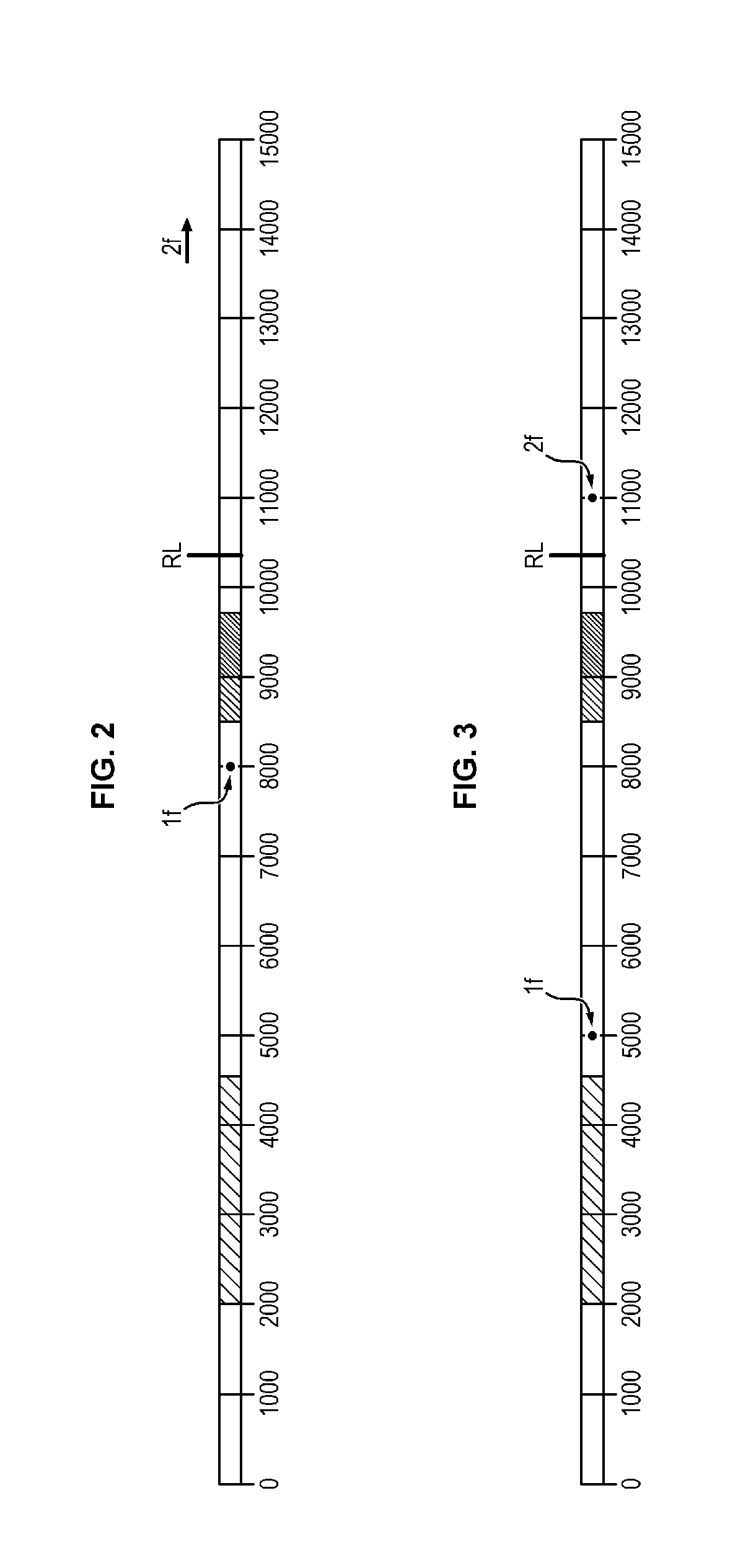
[0010] Modal analysis of the architecture of a given lowpressure shaft which conventionally has a front bearing and a rear bearing determines the values of critical speeds, the form of the modal distortions and the distribution of the deformation energy between the components of the shaft line: the front and rear bearings and the shaft connecting these bearings. Reference could be made especially to FIG. 3 which illustrates modal analysis of a supercritical low pressure shaft of a turbofan engine at high dilution rate according to the prior art. This figure shows, in revolutions per minute, the ground speed (from 2000 to 4500 rpm), cruising speed (from 8500 to 9500 rpm), takeoff speed (from 9000 to 9750 rpm) for an example of a turbofan engine having an absolute maximal speed encountered by the lowpressure shaft throughout the flight (or "redline") of 10000 rpm. In particular, this figure provides a critical speed value for the first flexural deformation mode of the lowpressure shaft, called mode 1f appears at a critical speed of the order of 5000 rpm. But to limit the zone of potential appearance of instabilities (nonsynchronous vibrations), this mode 1f must be higher in frequency. Also, the second flexural deformation mode of the lowpressure shaft, called mode 2f, occurs at a critical speed of the order of 11000 rpm, which is too close to the redline and results in overloading of the engine structure.
[0011] It is therefore necessary to dimension the lowpressure shaft to reject the deformation modes outside the operating ranges of the turbofan engine, or at least ensure that they occur in transient phase only, and therefore over a sufficiently short period to reduce the risk of damage to the turbofan engine. In fact, the appearance of such deformation modes can result in preventing the rise in speed of the engine due to the extensive reach of the lowpressure shaft and/or in generating nonsynchronous vibrations, resulting in an uncontrolled increase diverging from the dynamic response of the shaft beyond the critical speed corresponding to mode 1f.
[0012] For this, it is especially possible to increase the diameter of the low pressure shaft, although such an increase is not preferable in a turbofan engine at high dilution rate, to the extent where it also involves an increase of the bulk of the main body, and therefore a drop in the dilution rate.
SUMMARY OF THE INVENTION
[0013] An aim of the invention is therefore to propose a bypass turbofan engine and at high dilution rate, which has a sound dynamic situation, that is, whereof the deformation modes appear outside operating ranges, or at least only during transient phases of the turbofan engine.
[0014] For this, the invention proposes a bypass turbofan engine comprising: [0015] a turbine shaft, [0016] a fan shaft, and [0017] a reduction mechanism, coupling the turbine shaft and the fan shaft.
[0018] The turbofan engine has a dilution ratio greater than or equal to 10. Also, the turbine shaft is supported by four bearings such that the flexural deformation modes of the turbine shaft are positioned in transient phase or outside the operating range of the turbofan engine.
[0019] Some preferred though nonlimiting characteristics of the turbofan engine described above are the following, taken individually or in combination : [0020] the turbofan engine also comprises, from upstream to downstream in the direction of flow of gases in the turbofan engine: a fan, driven by the fan shaft, a lowpressure compressor, driven by the turbine shaft, a highpressure compressor, and a turbine, which drives in rotation the turbine shaft, [0021] the turbofan engine also comprises an intercompressor housing, extending between the lowpressure compressor and the highpressure compressor, and wherein a first of the four bearings which supports the turbine shaft is mounted on the intercompressor housing, [0022] the turbofan engine also comprises a vein housing extending between the reduction mechanism and the lowpressure compressor, and wherein a second of the four bearings which supports the turbine shaft is mounted on the vein housing, [0023] the first of the four bearings is equipped with a supple cage and can also comprise an oil film damper, whereas the second of the four bearings is devoid of supple cage, [0024] the turbofan engine also comprises a discharge housing extending downstream from the turbine, and wherein a third of the four bearings is mounted on the discharge housing, [0025] the turbine comprises, from upstream to downstream, a highpressure turbine and a lowpressure turbine separated by an interturbine housing, the fourth of the four bearings being mounted on the interturbine housing, upstream from the third bearing, [0026] the fourth of the four bearings is equipped with a supple cage and can also comprise an oil film damper, whereas the third of the four bearings is devoid of supple cage, [0027] the highpressure compressor is driven by a highpressure shaft, said highpressure shaft being mounted on a front bearing, extending downstream from the first of the four bearings, and a rear bearing, [0028] the highpressure compressor comprises at least eight rotor stages, for example between eight and twelve rotor stages, [0029] an overall compression rate of the lowpressure compressor and of the highpressure compressor is greater than or equal to 30, preferably greater than or equal to 40, [0030] the dilution ratio of the turbofan engine is between 12 and 18, [0031] a reduction ratio of the reduction mechanism is between 2.5 and 5, and/or [0032] an absolute maximal speed encountered by the turbine shaft is between 8000 revolutions per minute and 12 000 revolutions per minute, typically around 10 000 revolutions per minute.
BRIEF DESCRIPTION OF THE DIAGRAMS
[0033] Other characteristics, aims and advantages of the present invention will emerge more clearly from the following detailed description and with respect to the appended drawings given by way of nonlimiting examples and in which:
[0034] FIG. 1 is a schematic view of an embodiment of a turbofan engine according to the invention,
[0035] FIG. 2 is a modal analysis of an embodiment of a supercritical low pressure shaft of a turbofan engine at high dilution rate according to the invention, and
[0036] FIG. 3 is a modal analysis of a supercritical lowpressure shaft of a turbofan engine at high dilution rate according to the prior art.
DETAILED DESCRIPTION OF AN EMBODIMENT
[0037] In the following, a turbofan engine 1 will now be described in reference to the attached figures.
[0038] The turbofan engine 1 conventionally comprises a fan 2 and a primary body. In the direction of flow of gases the primary body comprises a lowpressure compressor 3, a highpressure compressor 4, a combustion chamber 5, a high pressure turbine 6, a lowpressure turbine 7 and a discharge nozzle 7 for gas.
[0039] The fan 2 comprises a fan disc 2 provided with fan blades 9 on its periphery, which, when set in rotation drive the airflow in the primary and secondary flow spaces of the turbofan engine 1. The disc fan 2 is supported by a lowpressure shaft 10 which is driven in rotation by the lowpressure turbine 7.
[0040] The turbofan engine 1 also comprises an intercompressor housing 11 whereof the hub is arranged between the housing of the lowpressure compressor 3 and the housing of the highpressure compressor 4.
[0041] The turbofan engine 1 has a high dilution rate, that is, a dilution rate greater than or equal to 10, for example between 12 and 18, to improve the propulsive output of the turbofan engine 1, and reduce its specific consumption and noise emitted by the fan 2.
[0042] For this reason, the fan 2 is disconnected from the lowpressure turbine 7 by means of a reduction mechanism 12. The fan 2 is driven by the lowpressure shaft 10 by means of a reducer of star gear or planetary type, placed between the upstream end of the lowpressure shaft 10 and the fan 2 and a fan shaft 20 which is fixed between the reduction mechanism 12 and the disc of the fan 2.
[0043] To calculate the dilution ratio, the rate of the secondary flow and the rate of the primary flow are measured when the turbofan engine 1 is stationary at takeoff speed in a standard atmosphere (such as defined by the manual of the International Civil Aviation Organisation (OACI), Doc 7488/3, 3rd edition) and at sea level.
[0044] In an embodiment, the reduction mechanism 12 comprises a star gear reduction mechanism 12.
[0045] The reduction ratio of the reduction mechanism 12 is preferably between 2.5 and 5.
[0046] The diameter of the fan 2 can be between eighty inches (203.2 centimeters) and one hundred inches (254.0 centimeters), preferably between eighty inches (203.2 centimeters) and ninety inches (228.6 centimeters).
[0047] The deformation modes of the turbofan engine 1 depend especially on the sizing of the lowpressure shaft 10 and the absolute maximal speed encountered by the lowpressure shaft 10 throughout ("redline", RL).
[0048] The redline RL of the lowpressure shaft 10 is fixed during the manufacturing phase of the turbofan engine 1. In this case, the redline RL is between 8000 revolutions per minute and 12 000 revolutions per minute, typically around 10 000 revolutions per minute.
[0049] In conventional terms, the length of the lowpressure shaft 10 is fixed by the length of the body highpressure, that is, the length of the highpressure compressor 4, of the combustion chamber 5 and of the highpressure turbine 6. Here, the highpressure compressor 4 comprises a series of rotating discs (rotor stages), bladed or not, and a series of fixed blade discs (rectifying stages). More precisely, the highpressure compressor 4 comprises at least eight rotor stages, for example between eight and twelve rotor stages.
[0050] Also, the overall pressure ratio (OPR) of the compressor of the turbofan engine 1 is at least equal to 30, preferably greater than or equal to 40.
[0051] Overall pressure ratio OPR here means the ratio between the pressure at the intake of the lowpressure compressor 3 (or "booster") and the pressure at outlet of the highpressure compressor 4.
[0052] Because of the high number of rotor stages in the highpressure compressor 4 and the high overall pressure ratio OPR, the compressor of the turbofan engine 1 exhibits better power output without overloading the booster 3. Such a pressure ratio can especially be attained by way of the reduction mechanism 12 between the fan 2 and the lowpressure turbine 7, which reduces the mass of the turbofan engine 1.
[0053] The lowpressure shaft 10 is centred on the axis of the turbofan engine 1 by a series of bearings. In this case, the lowpressure shaft 10 is supported by four bearings BP#1, BP#2, BP#3, BP#4: in this configuration, the deformation modes of the lowpressure shaft 10 are shifted to transient speed of the turbofan engine 1, with safety margins relative to stabilised speeds. Reference could be made especially to FIG. 2 which illustrates modal analysis of a supercritical low pressure shaft 10 of a turbofan engine 1 at high dilution rate according to the invention, comprising successively four bearings BP#1, BP#2, BP#3 and BP#4. This figure shows, in revolutions per minute, the ground speed (from 2000 to 4500 rpm), the cruising speed (from 8500 to 9500 rpm), the takeoff speed (from 9000 to 9750 rpm) for an example of turbofan engine 1 having a redline RL of 10000 rpm. Also, the first flexural deformation mode 1f appears, for this turbofan engine 1 comprising four bearings BP#1, BP#2, BP#3 and BP#4, at 8000 rpm, whereas the second mode 2f appears beyond the redline RL. In an embodiment, the second mode 2f appears beyond 110% of the redline RL to ensure a safety margin.
[0054] The bearing BP#1 corresponds to the bearing farthest from the low pressure shaft 10 whereas the bearing BP#4 is the bearing farthest downstream. The bearings BP#2 and BP#3 therefore extend between the bearing BP#1 and the bearing BP#2.
[0055] The applicant accordingly noticed that the position of the bearing BP#2 and of the bearing BP#3 had a strong influence on the deformation modes of the low pressure shaft 10.
[0056] In this way, the bearing BP#3, which is adjacent to the bearing BP#4, can be mounted both on the lowpressure shaft 10 and also on the interturbine housing 13 (that is, on the housing extending between the housing containing the highpressure turbine 6 and the housing containing the lowpressure turbine 7), upstream from the lowpressure turbine 7. In an embodiment, the bearing BP#3 extends downstream from the bearing HP#2, which is the bearing farthest downstream from the highpressure shaft 14.
[0057] The bearing BP#2, which extends between the bearing BP#1 and the bearing BP#3 in the direction of flow of gases in the turbofan engine 1, can be mounted both on the lowpressure shaft 10 and also part on the intercompressor housing 11, or between the booster 3 and the highpressure compressor 4. In an embodiment, the bearing BP#2 extends upstream from the bearing HP#1 which is the bearing farthest upstream from the highpressure shaft 14.
[0058] The position of the bearings BP#1 and BP#4 can be conventional. For example, as seen in FIG. 1, the bearing BP#1, located farthest upstream from the lowpressure shaft 10, can be mounted both on the lowpressure shaft 10 and also part on the vein housing 17 which extends between the reduction mechanism 12 and the booster 3.
[0059] The bearing BP#4, which is located farthest downstream from the low pressure shaft 10, can be mounted both on the lowpressure shaft 10 and also on the discharge housing 16 of the turbofan engine 1.
[0060] As seen is FIG. 2, mounting the lowpressure shaft 10 on four bearings BP#1, BP#2, BP#3 and BP#4 (rather than two or three bearings, as in the prior art), and judiciously placing the bearings BP#2 and BP#3, effectively shifts the flexural deformation modes 1f, 2f of the lowpressure shaft 10: the mode 1f is positioned in a transient phase of the operating range and with safety margins relative to stabilised speeds whereas the mode 2f is positioned outside the operating range and with a comfortable margin relative to the redline RL. In other terms, the lowpressure shaft 10 stays at critical speed only very briefly. Typically, the mode 1f can be placed between ground idling and cruising/takeoff speeds. At takeoff, the turbofan engine shifts from an idling speed close to the minimum of the engine to a speed takeoff near the Redline: the critical speed of the low pressure shaft is therefore likely to appear during transition between these two speeds.
[0061] It also becomes possible, without as such risking a flexural deformation mode appearing at stabilised speed, to reduce the diameter of the lowpressure shaft 10 and therefore the bulk of the primary body to achieve, with the reduction mechanism 12 and the considerable diameter of the fan 2, a high dilution rate for the turbofan engine 1. Typically, the lowpressure shaft 10 can have an external diameter of under fifty millimeters, typically under forty-five millimeters.
[0062] This positioning of the bearings BP#1, BP#2, BP#3, BP#4 also reduces clearance usage (radial displacement) of the booster 3, the latter now being placed between the two bearings BP#2 and BP#3.
[0063] In an embodiment, the bearing BP#1 can be devoid of supple cage 15 (also known by the name cage squirrel) and oil squeeze film damper.
[0064] Oil squeeze film damper here means a housing formed in a support housing of the corresponding bearing and wherein the external ring of the bearing is mounted with slight radial play. An annular space delimited around the ring in this housing is filled with oil and is closed axially by annular sealing elements which are free in rotation in annular throats of the external ring of the bearing and which cooperate as a seal with an internal cylindrical surface of the housing. Oil intake orifices are formed in the housing and terminate in the abovementioned annular space and oil discharge orifices are formed in the annular sealing elements and terminate outside this annular space to have oil circulating continuously in the annular space and cooled down outside this space to evacuate thermal energy dissipated by friction resulting from compression of a film of oil by the external ring of the bearing during its orbital movements in the abovementioned housing. The supple cage 15 as such is generally made solid with the external ring of the bearing. Reference could be made especially to document FR 2 876 758 in the name of the applicant, which describes a bearing embodiment comprising an oil squeeze film damper and a supple cage.
[0065] The absence of supple cage 15 and oil squeeze film damper therefore the makes for easier integration of the bearing BP#1, to the extent where the space available in the region of the booster 3 is relatively narrow.
[0066] A supple cage 15 and an oil squeeze film damper can however be placed on the bearing BP#2. This supple cage 15 can easily be integrated into this bearing BP#2, the space between the intercompressor housing 11 and the lowpressure shaft 10 being greater than in the region of the booster 3.
[0067] In a variant embodiment, a supple cage 15 and an oil film damper can also be placed on the bearing BP#3, where the available space is also greater.
[0068] This configuration better dampens the vibrations of the lowpressure shaft 10, the oil film damper being more effective in this position. At the critical speed, the lowpressure shaft does not orbit in the region of the nodes and its orbiting is maximal in the region of the underside; approaching the oil squeeze film damper from the underside therefore heightens its efficacy as the articulation in the oil film is greater.
[0069] Optionally, the fourth bearing can also be devoid of supple cage 15 and oil film damper. In this variant embodiment, only the bearings BP#2 and BP#3 are therefore equipped with a supple cage 15 and an oil film damper.
* * * * *
D00000
D00001
D00002
XML
uspto.report is an independent third-party trademark research tool that is not affiliated, endorsed, or sponsored by the United States Patent and Trademark Office (USPTO) or any other governmental organization. The information provided by uspto.report is based on publicly available data at the time of writing and is intended for informational purposes only.
While we strive to provide accurate and up-to-date information, we do not guarantee the accuracy, completeness, reliability, or suitability of the information displayed on this site. The use of this site is at your own risk. Any reliance you place on such information is therefore strictly at your own risk.
All official trademark data, including owner information, should be verified by visiting the official USPTO website at www.uspto.gov. This site is not intended to replace professional legal advice and should not be used as a substitute for consulting with a legal professional who is knowledgeable about trademark law.