Cam Shaft Phaser With Crankshaft Driven Rotor
Pawade; Vaishnavi ; et al.
U.S. patent application number 15/815762 was filed with the patent office on 2019-05-23 for cam shaft phaser with crankshaft driven rotor. This patent application is currently assigned to Schaeffler Technologies AG &. The applicant listed for this patent is Schaeffler Technologies AG & Co. KG. Invention is credited to Jason Durfee, Vaishnavi Pawade.
| Application Number | 20190153907 15/815762 |
| Document ID | / |
| Family ID | 66533877 |
| Filed Date | 2019-05-23 |


View All Diagrams
| United States Patent Application | 20190153907 |
| Kind Code | A1 |
| Pawade; Vaishnavi ; et al. | May 23, 2019 |
CAM SHAFT PHASER WITH CRANKSHAFT DRIVEN ROTOR
Abstract
A cam shaft phaser, including: an axis of rotation; a rotor arranged to receive torque from an engine and including a plurality of radially outwardly extending protrusions; a stator including a plurality of radially inwardly extending protrusions; and a plurality of chambers. Each chamber is circumferentially bounded by first and second radially outwardly extending protrusions. A respective radially inwardly extending protrusion is located in each chamber.
| Inventors: | Pawade; Vaishnavi; (Rochester Hills, MI) ; Durfee; Jason; (Troy, MI) | ||||||||||
| Applicant: |
|
||||||||||
|---|---|---|---|---|---|---|---|---|---|---|---|
| Assignee: | ; Schaeffler Technologies AG
& Herzogenaurach DE |
||||||||||
| Family ID: | 66533877 | ||||||||||
| Appl. No.: | 15/815762 | ||||||||||
| Filed: | November 17, 2017 |
| Current U.S. Class: | 1/1 |
| Current CPC Class: | F01L 1/344 20130101; F01L 1/3442 20130101; F01L 2250/02 20130101; F01L 2001/34463 20130101; F01L 2001/34456 20130101; F01L 2001/0537 20130101; F01L 1/026 20130101; F01L 2001/34479 20130101; F01L 2001/34469 20130101; F01L 2303/02 20200501; F01L 2250/04 20130101 |
| International Class: | F01L 1/344 20060101 F01L001/344; F01L 1/02 20060101 F01L001/02 |
Claims
1. A cam shaft phaser, comprising: an axis of rotation; a rotor arranged to receive torque from an engine and including a plurality of radially outwardly extending protrusions; a stator including a plurality of radially inwardly extending protrusions; and, a plurality of chambers, wherein: each chamber is circumferentially bounded by first and second radially outwardly extending protrusions; and, a respective radially inwardly extending protrusion is located in each chamber.
2. The cam shaft phaser of claim 1, wherein the rotor is arranged to non-rotatably connect to a cam shaft.
3. The cam shaft phaser of claim 1, wherein: the stator is rotatable with respect to the rotor; and, the rotor is not rotatable with respect to the stator.
4. The cam shaft phaser of claim 1, wherein: the rotor has a first outer radius; the stator has a second outer radius; and, the second outer radius less than the first outer radius.
5. The cam shaft phaser of claim 1, further comprising: a sealing cover; a locking cover; and, a plurality of fasteners non-rotatably connecting the sealing cover, the stator, and the locking cover, wherein: the stator is axially disposed between the sealing cover and the rotor; and, the rotor is axially disposed between the stator and the locking cover.
6. The cam shaft phaser of claim 1, wherein: the rotor includes: a first axial side facing in a first axial direction; a second axial side facing in a second axial direction, opposite the first axial direction; and, a plurality of slots connecting the first axial side with the second axial side; the stator includes a plurality of axially extending protrusions; each axially extending protrusion is at least partially disposed in a respective slot; and, the stator is rotatable with respect to the rotor to circumferentially displace said each axially extending protrusion within the respective slot.
7. The cam shaft phaser of claim 6, further comprising: a sealing cover; a locking cover; and, a plurality of fasteners: passing through the plurality of slots; and, non-rotatably connecting the sealing cover, the stator, and the locking cover.
8. The cam shaft phaser of claim 6, wherein each slot includes: a planar radially innermost surface; and, a curved radially outermost surface.
9. The cam shaft phaser of claim 1, wherein: the rotor includes: a first axial side facing in a first axial direction; a second axial side facing in a second axial direction, opposite the first axial direction; and, a plurality of slots connecting the first axial side with the second axial side; the stator includes a plurality of axially extending protrusions; and, each axially extending protrusion is at least partially disposed in a respective slot; and, wherein: a first line, in an axial direction, passes through a radially inwardly extending protrusion and a slot; or, a second line, in an axial direction passes through a chamber and a slot; or, a third line, in an axial direction, passes through an axially extending protrusion and a slot.
10. The cam shaft phaser of claim 1, further comprising: a pin, wherein: the rotor includes: a central opening through which the axis of rotation passes; at least one first through-bore connecting the central opening with a chamber and arranged to transmit fluid to the chamber and to drain fluid from the chamber; a radially outwardly extending protrusion with a slot; a second through-bore connecting the slot with the chamber; the pin is disposed in the slot; in a first position for the pin, the pin non-rotatably connects the stator and the rotor; and, the second through-bore is arranged to transmit the fluid from the chamber to the slot to axially displace the pin to a second position in which the pin is disengaged from the stator.
11. The cam shaft phaser of claim 1, wherein each chamber includes: a respective advance chamber circumferentially bounded by the first radially outwardly extending protrusion and the respective radially inwardly extending protrusion; and, a respective retard chamber circumferentially bounded by the respective radially inwardly extending protrusion and the second radially outwardly extending protrusion.
12. A cam shaft phaser, comprising: an axis of rotation; a rotor including: a plurality of radially outwardly extending protrusions; and, a plurality of slots; a stator including: a plurality of axially extending protrusion, each axially extending protrusion disposed in a respective slot; and, a plurality of radially inwardly extending protrusions; and, a plurality of chambers, each chamber circumferentially bounded by first and second radially inwardly extending protrusions, wherein: a respective radially inwardly extending protrusion is located in each chamber; and, a line, parallel to the axis of rotation, passes through a chamber and a slot.
13. The cam shaft phaser of claim 12, further comprising: a sealing cover; a locking cover; and, a plurality of fasteners, wherein: the rotor is axially located between the stator and the locking cover; the stator is axially located between the sealing cover and the rotor; and, each fastener passes through a respective slot; and, the plurality of fasteners non-rotatably connects the sealing cover, the stator and the locking cover.
14. The cam shaft phaser of claim 13, wherein said each fastener passes through a respective axially extending protrusion.
15. The cam shaft phaser of claim 12, wherein: the stator is rotatable with respect to the rotor; and, said each axially extending protrusion is circumferentially displaceable within the respective slot.
16. A cam shaft phaser, comprising: an axis of rotation; a rotor including: a plurality of radially outwardly extending protrusions; and, a plurality of slots, each slot including: a planar radially innermost surface; and, a curved radially outermost surface; a stator including: a plurality of axially extending protrusion, each axially extending protrusion disposed in a respective slot; and, a plurality of radially inwardly extending protrusions; and, a plurality of chambers, each chamber circumferentially bounded by first and second radially outwardly extending protrusions, wherein a respective radially inwardly extending protrusion is located in each chamber.
17. A method of using the cam shaft phaser of claim 1, comprising: flowing fluid into the plurality of chambers; receiving, with the rotor, torque from a crankshaft for an internal combustion engine; rotating the rotor, the stator, and a cam shaft, non-rotatably connected to the rotor, in a first circumferential direction; flowing additional fluid into a plurality of first chambers included in the plurality of chambers; draining second fluid from a plurality of second chambers included in the plurality of chambers; and, rotating the stator with respect to the rotor.
18. The method of claim 17 further comprising: transmitting, with the stator, torque to a second cam shaft phaser.
19. A method of using the cam shaft phaser of claim 12, comprising: flowing fluid into the plurality of chambers; receiving, with the rotor, torque from a crankshaft for an internal combustion engine; rotating the rotor, the stator, and a cam shaft, non-rotatably connected to the rotor, in a first circumferential direction; flowing the fluid into a plurality of first chambers included in the plurality of chambers; draining the fluid from a plurality of second chambers included in the plurality of chambers; rotating the stator with respect to the rotor; and, circumferentially displacing said each axially extending protrusion in the respective slot.
20. The method of claim 19 further comprising: transmitting, with the stator, torque to a second cam shaft phaser.
Description
TECHNICAL FIELD
[0001] The present disclosure relates to a cam shaft phaser with a rotor arranged to receive rotational torque and a stator rotatable with respect to the rotor. In particular, a cam shaft is non-rotatably connected to the rotor and the stator provides rotational torque to another cam shaft phaser and cam shaft.
BACKGROUND
[0002] Known configurations for cam shaft phasers, in which a stator receives torque from an engine and the rotor is rotated with respect to the stator to phase a cam shaft connected to the rotor may not be desirable for certain power train configurations.
SUMMARY
[0003] According to aspects illustrated herein, there is provided a cam shaft phaser, including: an axis of rotation; a rotor arranged to receive torque from an engine and including a plurality of radially outwardly extending protrusions; a stator including a plurality of radially inwardly extending protrusions; and a plurality of chambers. Each chamber is circumferentially bounded by first and second radially outwardly extending protrusions. A respective radially inwardly extending protrusion is located in each chamber.
[0004] According to aspects illustrated herein, there is provided a cam shaft phaser, including: an axis of rotation; a rotor including a plurality of radially outwardly extending protrusions and a plurality of slots; a stator including a plurality of axially extending protrusion, each axially extending protrusion disposed in a respective slot and a plurality of radially inwardly extending protrusions; and a plurality of chambers, each chamber circumferentially bounded by first and second radially inwardly extending protrusions. A respective radially inwardly extending protrusion is located in each chamber. A line, parallel to the axis of rotation, passes through a chamber and a slot.
[0005] According to aspects illustrated herein, there is provided a cam shaft phaser, including: an axis of rotation; a rotor including a plurality of radially outwardly extending protrusions and a plurality of slots, each slot including a planar radially innermost surface and a curved radially outermost surface; a stator including a plurality of axially extending protrusion, each axially extending protrusion disposed in a respective slot and a plurality of radially inwardly extending protrusions; and a plurality of chambers, each chamber circumferentially bounded by first and second radially outwardly extending protrusions. A respective radially inwardly extending protrusion is located in each chamber.
BRIEF DESCRIPTION OF THE DRAWINGS
[0006] Various embodiments are disclosed, by way of example only, with reference to the accompanying schematic drawings in which corresponding reference symbols indicate corresponding parts, in which:
[0007] FIG. 1 is a front perspective view of an example cam shaft phaser with crankshaft driven rotor;
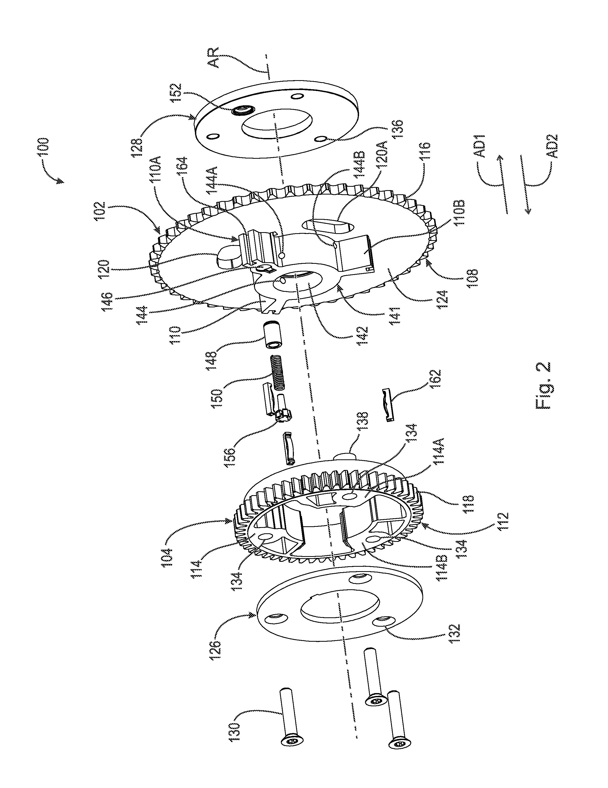
[0008] FIG. 2 is a back perspective view of the cam shaft phaser shown in FIG. 1;
[0009] FIG. 3 is a front view of the cam shaft phaser shown in FIG. 1;
[0010] FIG. 4 is a back view of a rotor shown in FIG. 1;
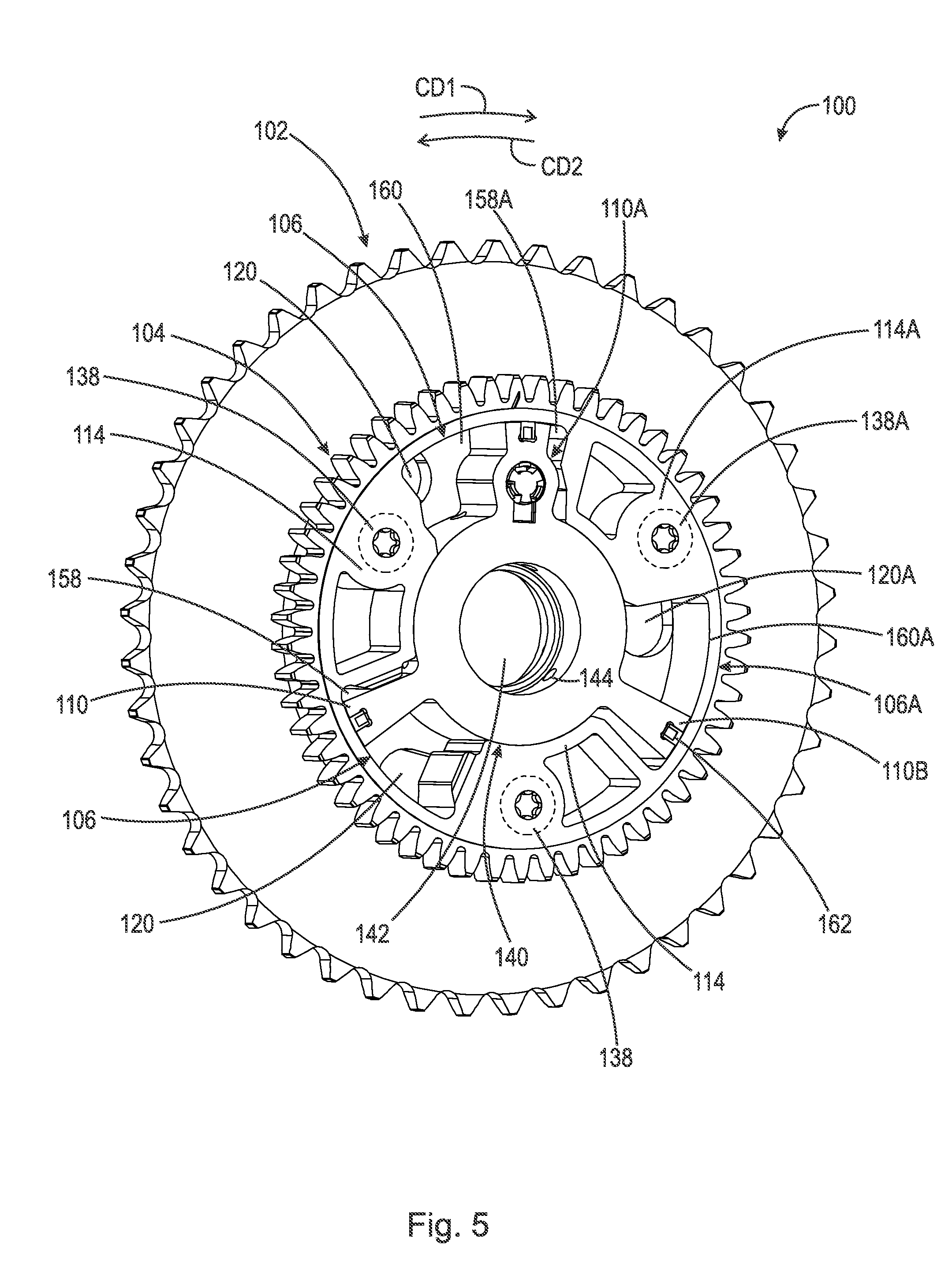
[0011] FIG. 5 is a perspective back view of the cam shaft phaser shown in FIG. 1 with a sealing cover removed;
[0012] FIG. 6 is a back view of the cam shaft phaser shown in FIG. 1 with the sealing cover removed;
[0013] FIG. 7 is a perspective front view of the cam shaft phaser shown in FIG. 1 with a locking cover removed;
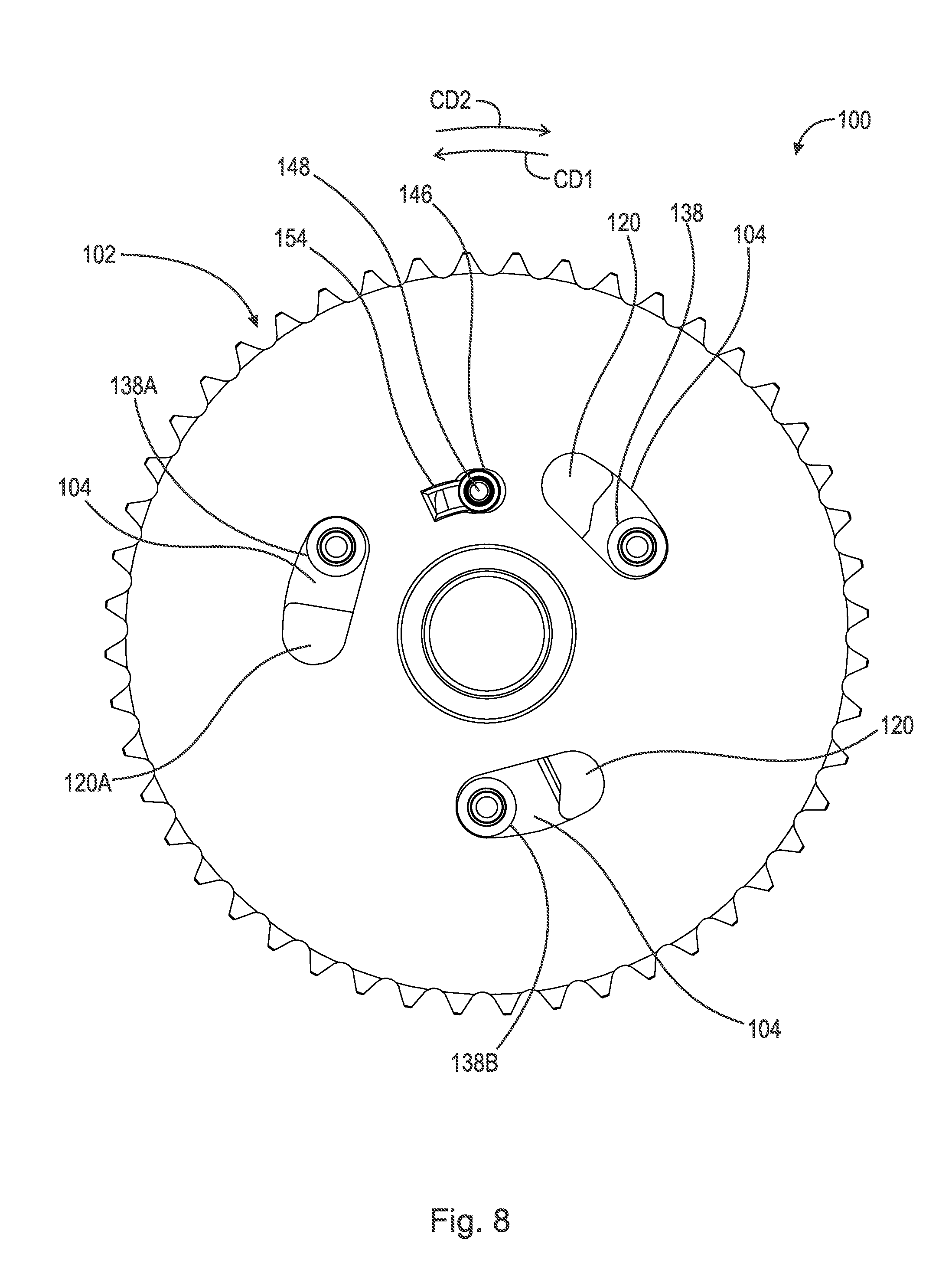
[0014] FIG. 8 is a front view of the cam shaft phaser shown in FIG. 1 with the locking cover removed;
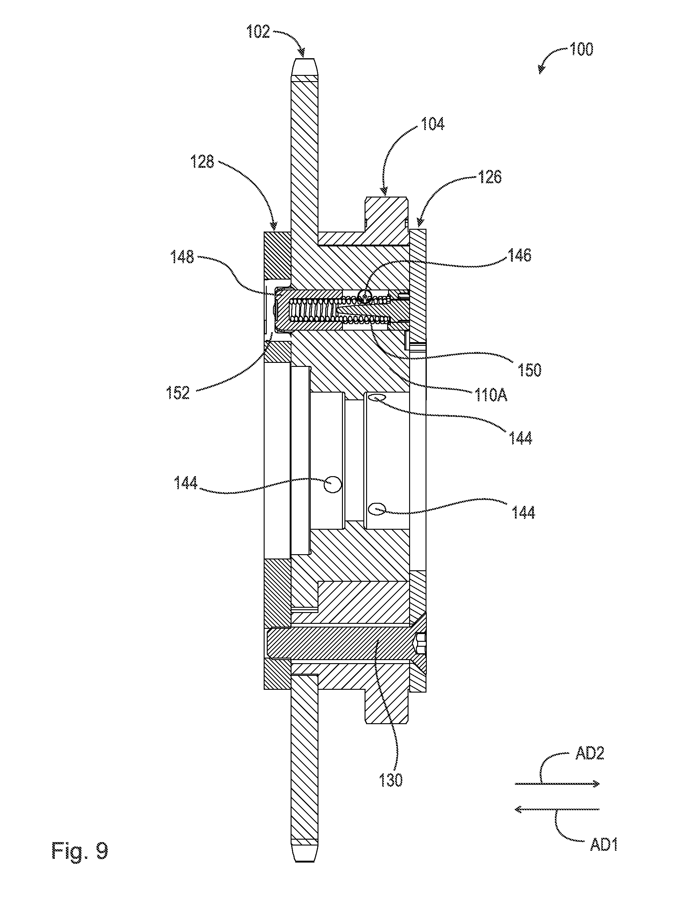
[0015] FIG. 9 is a cross-sectional view generally along line 9-9 in FIG. 3;
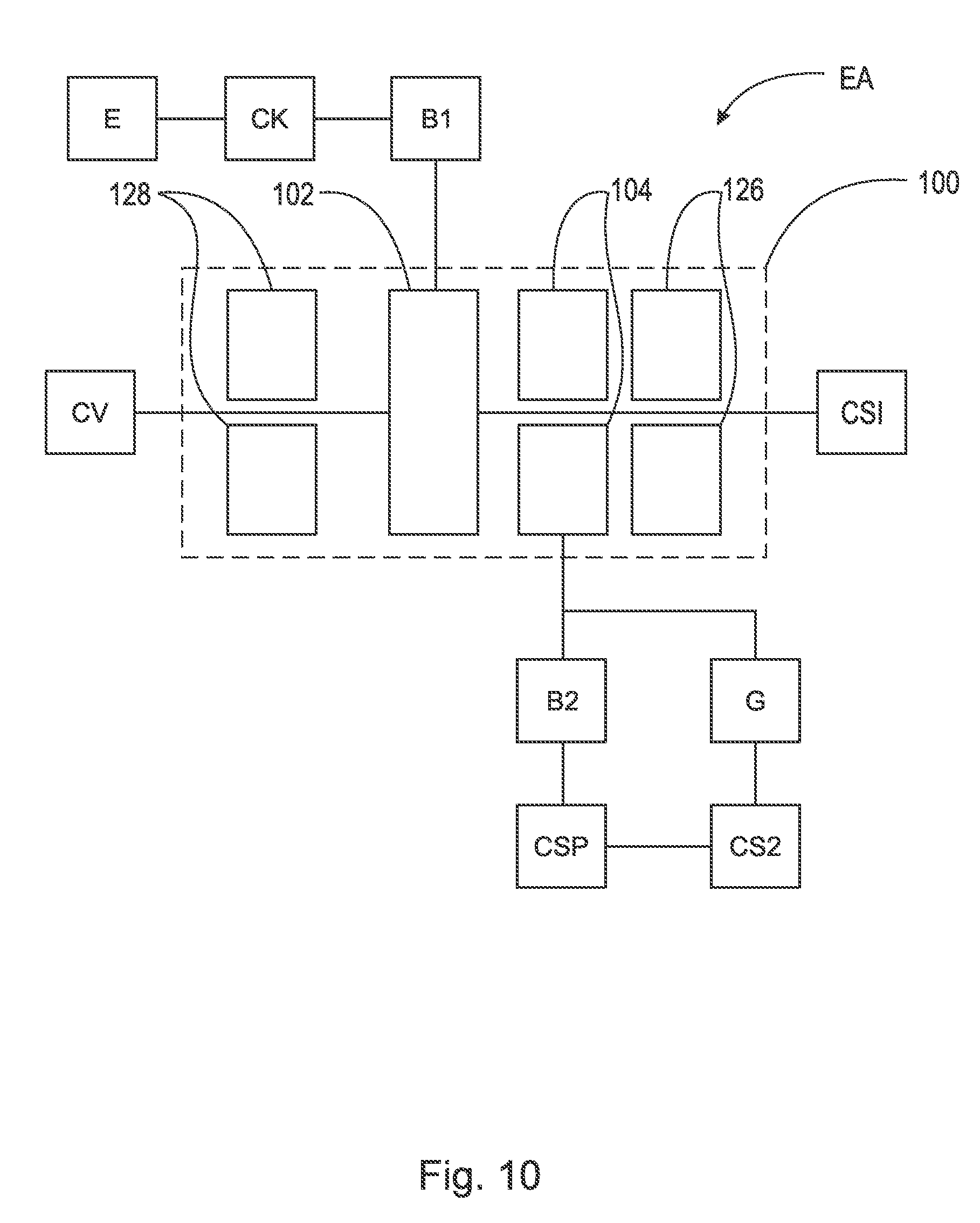
[0016] FIG. 10 is a block diagram of an engine assembly including the cam shaft phaser shown in FIG. 1; and,
[0017] FIG. 11 is a perspective view of a cylindrical coordinate system demonstrating spatial terminology used in the present application.
DETAILED DESCRIPTION
[0018] At the outset, it should be appreciated that like drawing numbers on different drawing views identify identical, or functionally similar, structural elements of the disclosure. It is to be understood that the disclosure as claimed is not limited to the disclosed aspects.
[0019] Furthermore, it is understood that this disclosure is not limited to the particular methodology, materials and modifications described and as such may, of course, vary. It is also understood that the terminology used herein is for the purpose of describing particular aspects only, and is not intended to limit the scope of the present disclosure.
[0020] Unless defined otherwise, all technical and scientific terms used herein have the same meaning as commonly understood to one of ordinary skill in the art to which this disclosure belongs. It should be understood that any methods, devices or materials similar or equivalent to those described herein can be used in the practice or testing of the disclosure.
[0021] FIG. 11 is a perspective view of cylindrical coordinate system 10 demonstrating spatial terminology used in the present application. The present application is at least partially described within the context of a cylindrical coordinate system. System 10 includes axis of rotation, or longitudinal axis, 11, used as the reference for the directional and spatial terms that follow. Opposite axial directions AD1 and AD2 are parallel to axis 11. Radial direction RD1 is orthogonal to axis 11 and away from axis 11. Radial direction RD2 is orthogonal to axis 11 and toward axis 11. Opposite circumferential directions CD1 and CD2 are defined by an endpoint of a particular radius R (orthogonal to axis 11) rotated about axis 11, for example clockwise and counterclockwise, respectively.
[0022] To clarify the spatial terminology, objects 12, 13, and 14 are used. As an example, an axial surface, such as surface 15A of object 12, is formed by a plane co-planar with axis 11. However, any planar surface parallel to axis 11 is an axial surface. For example, surface 15B, parallel to axis 11 also is an axial surface. An axial edge is formed by an edge, such as edge 15C, parallel to axis 11. A radial surface, such as surface 16A of object 13, is formed by a plane orthogonal to axis 11 and co-planar with a radius, for example, radius 17A. A radial edge is co-linear with a radius of axis 11. For example, edge 16B is co-linear with radius 17B. Surface 18 of object 14 forms a circumferential, or cylindrical, surface. For example, circumference 19, defined by radius 20, passes through surface 18.
[0023] Axial movement is in axial direction AD1 or AD2. Radial movement is in radial direction RD1 or RD2. Circumferential, or rotational, movement is in circumferential direction CD1 or CD2. The adverbs "axially," "radially," and "circumferentially" refer to movement or orientation parallel to axis 11, orthogonal to axis 11, and about axis 11, respectively. For example, an axially disposed surface or edge extends in direction AD1, a radially disposed surface or edge extends in direction RD1, and a circumferentially disposed surface or edge extends in direction CD1.
[0024] FIG. 1 is a front perspective view of example cam shaft phaser 100 with a crankshaft driven rotor.
[0025] FIG. 2 is a back perspective view cam shaft phaser 100 shown in FIG. 1.
[0026] FIG. 3 is a front view of cam shaft phaser 100 shown in FIG. 1.
[0027] FIG. 4 is a back view of a rotor shown in FIG. 1.
[0028] FIG. 5 is a perspective back view of cam shaft phaser 100 shown in FIG. 1 with a sealing cover removed.
[0029] FIG. 6 is a back view of cam shaft phaser 100 shown in FIG. 1 with the sealing cover removed. The following should be viewed in light of FIGS. 1 through 6. Cam shaft phaser 100 includes: axis of rotation AR; rotor 102; stator 104; and chambers 106. Rotor 102 includes: radially outermost surface 108; outer radius R1; and radially outwardly extending protrusions 110. Stator 104 includes: radially outermost surface 112; outer radius R2; and radially inwardly extending protrusions 114. In an example embodiment, radius R2 is less than radius R1. In an example embodiment, surface 108 includes teeth 116 and surface 112 includes teeth 118.
[0030] FIG. 6 is a back view of cam shaft phaser 100 shown in FIG. 1 with the sealing cover removed.
[0031] FIG. 7 is a perspective front view of cam shaft phaser 100 shown in FIG. 1 with a locking cover removed.
[0032] FIG. 8 is a front view of cam shaft phaser 100 shown in FIG. 1 with the locking cover removed. The following should be viewed in light of FIGS. 1 through 8. Each chamber 106 is circumferentially bounded by a pair of circumferentially adjacent radially outwardly extending protrusions 110. A respective radially inwardly extending protrusion 114 is located in each chamber 106. For example: chamber 106A is circumferentially bounded by circumferentially adjacent radially outwardly extending protrusions 110A and 110B; and radially inwardly extending protrusion 114A is located in chamber 106A. A reference character "[number][number][number][letter]" represents a specific example of a group of elements "[number][number][number]." For example, chamber 106A is a specific example of chambers 106.
[0033] As further described below, stator 104 is rotatable with respect to rotor 102 and rotor 102 is not rotatable with respect to stator 104. That is, rotor 102 is the relative ground for cam shaft phaser 100 and phasing is performed by rotating stator 104 with respect to rotor 102.
[0034] Rotor 102 includes slots 120. Slots 120 connect axial sides 122 and 124 of rotor 102, facing in axial directions AD1 and AD2, respectively. In an example embodiment, cam shaft phaser 100 includes sealing cover 126, locking cover 128 and fasteners 130. Fasteners 130 pass through: through-bores 132 in cover 126; through-bores 134 in protrusions 114; and slots 120. Fasteners 130 thread into threaded bores 136 in cover 128, and non-rotatably connect sealing cover 126, stator 104, and locking cover 128. Therefore, stator 104 and covers 126 and 128 are rotatable with respect to rotor 102. Rotor 102 and stator 104 are axially disposed between covers 126 and 128. In an example embodiment, stator 104 is axially disposed between sealing cover 126 and rotor 102; and rotor 102 is axially disposed stator 104 and locking cover 128. In an example embodiment (not shown), rotor 102 is axially disposed between sealing cover 126 and stator 104; and stator 104 is axially disposed rotor 102 and locking cover 128. By "non-rotatably connected" components, we mean that: the components are connected so that whenever one of the components rotates, all the components rotate; and relative rotation between the components is not possible. Radial and/or axial movement of non-rotatably connected components with respect to each other is possible, but not required.
[0035] Stator 104 includes axially extending protrusions 138. Each protrusion 138 extends in axial direction AD1 from a respective protrusion 114. For example, protrusion 138A extends from protrusion 114A in direction AD1. Through-bores 134 pass through axially extending protrusions 138. Each axially extending protrusion 138 is at least partially disposed in a respective slot 120. For example, protrusion 138A is partially disposed in slot 120A. Stator 104 is rotatable with respect to rotor 102 to circumferentially displace each axially extending protrusion 138 within the respective slot 120. In an example embodiment, each slot 120 includes planar radially innermost surface 139 and radially outermost surface 140 curved in circumferential direction CD1.
[0036] Line L1, in axial direction AD1, passes through radially inwardly extending protrusion 114B and slot 120B without passing through chamber 106B. Line L2, in axial direction AD1, passes through chamber 106B and slot 120B. Line L3, in axial direction AD1, passes through chamber 106B and stator 104 without passing through slot 120B. Line L4 passes through protrusion 138B and slot 120B without passing through chamber 106B.
[0037] FIG. 9 is a cross-sectional view generally along line 9-9 in FIG. 3. In an example embodiment, rotor 102 includes hub 141. Hub 141 includes central opening 142 through axis AR passes and supply channels 144. Protrusions 110 extend radially outwardly from hub 141. As is known in the art, fluid is transmitted into chambers 106 and is drained from chambers 106 via channels 144.
[0038] In an example embodiment: protrusion 110A includes slot 146; cam shaft phaser 100 includes locking pin 148 and spring 150, each disposed in slot 146; cover 128 includes indentation 152; and rotor 102 includes channel 154 connecting chamber 106A and slot 146. In an example embodiment, cam shaft phaser 100 includes spring support 156. Spring 150 urges pin 148 in axial direction AD1. In a first position for pin 148, which is a locked mode for cam shaft phaser 100, spring 150 displaces pin 148 in direction AD1 and into indentation 152, non-rotatably connecting cover 128, rotor 102, stator 104 and cover 126. Non-rotatably connecting rotor 102 to cover 128 non-rotatably connects rotor 102 to stator 104 and cover 126.
[0039] The discussion that follows assumes an advance phase adjustment entails rotating stator 104 in circumferential direction CD1 with respect to rotor 102, and a retard phase adjustment entails rotating stator 104 in circumferential direction CD2 with respect to rotor 102. In the example of FIGS. 1 through 9, each chamber 106 includes a respective advance chamber 158 and a respective retard chamber 160. Each chamber 158 is circumferentially bounded in directions CD1 and CD2 by a protrusion 114 and a protrusion 110, respectively. Each chamber 160 is circumferentially bounded in directions CD1 and CD2 by a protrusions 110 and a protrusion 114, respectively. For example: advance chamber 158A is circumferentially bounded in directions CD1 and CD2 by protrusions 114A and 110A, respectively; and retard chamber 160A is circumferentially bounded in directions CD1 and CD2 by protrusions 110B and 114A, respectively. In an example embodiment, seals 162 in slots 164 in protrusions 110 seal chambers 158 from chambers 160. In the example of FIGS. 1 through 9: channel 154 connects slot 146 and chamber 158A; and channels 144A and 144B supply and drain fluid from chambers 158A and 160A, respectively.
[0040] To transition from the locked mode to an unlocked mode, in which stator 104 is rotatable with respect to rotor 102, fluid is supplied to chamber 158A by channel 144A. The fluid flows through channel 154 to slot 146 and displaces pin 148 in direction AD2, against the urging of spring 150, to disengage pin 148 from indentation 152.
[0041] FIG. 10 is a block diagram of engine assembly AS including cam shaft phaser 100 shown in FIG. 1. In the example of FIG. 10, cam shaft CS1 is non-rotatably connected to rotor 102 and belt (or chain) B1 is connected to teeth 116 of rotor 102 and crankshaft CK for engine E. Therefore, crankshaft CK rotates rotor 102 and cam shaft CS1. Stator 104 is used to rotate cam shaft CS2. For example: cam shaft phaser CSP is connected to cam shaft phaser 100 by belt (or chain) B2 to teeth 118 of stator 104; belt B2 transmits rotational torque to cam shaft phaser CSP; and phaser CSP rotates cam shaft CS2. For example: teeth 118 are mated with gear G on cam shaft CS2; and stator 104 rotates and phases cam shaft CS2 via gear G. Phasing cam shaft CS2 with respect to cam shaft CS1 is accomplished by rotating stator 104 with respect to rotor 102.
[0042] It will be appreciated that various of the above-disclosed and other features and functions, or alternatives thereof, may be desirably combined into many other different systems or applications. Various presently unforeseen or unanticipated alternatives, modifications, variations, or improvements therein may be subsequently made by those skilled in the art which are also intended to be encompassed by the following claims.
LIST OF REFERENCE CHARACTERS
[0043] 10 cylindrical system [0044] 11 axis of rotation [0045] AD1 axial direction [0046] AD2 axial direction [0047] RD1 radial direction [0048] RD2 radial direction [0049] CD1 circumferential direction [0050] CD2 circumferential direction [0051] R radius [0052] 12 object [0053] 13 object [0054] 14 object [0055] 15A surface [0056] 15B surface [0057] 15C edge [0058] 16A surface [0059] 16B edge [0060] 17A radius [0061] 17B radius [0062] 18 surface [0063] 19 circumference [0064] 20 radius [0065] AR axis of rotation [0066] B1 belt or chain [0067] B2 belt or chain [0068] CK crank shaft [0069] CS1 cam shaft [0070] CS2 cam shaft [0071] CSP cam shaft phaser [0072] CV control valve [0073] E engine [0074] G gear [0075] L1 axial line [0076] L2 axial line [0077] L3 axial line [0078] L4 axial line [0079] R1 outer radius, rotor [0080] R2 outer radius, stator [0081] 100 cam shaft phaser [0082] 102 rotor [0083] 104 stator [0084] 106 chamber [0085] 106A chamber [0086] 106B chamber [0087] 108 radially outermost surface, rotor [0088] 110 radially outwardly extending protrusion, rotor [0089] 110A radially outwardly extending protrusion, rotor [0090] 110B radially outwardly extending protrusion, rotor [0091] 112 radially outermost surface, stator [0092] 114 radially inwardly extending protrusion, stator [0093] 114A radially inwardly extending protrusion, stator [0094] 114B radially inwardly extending protrusion, stator [0095] 116 teeth, rotor [0096] 118 teeth, stator [0097] 120 slot, rotor [0098] 120A slot, rotor [0099] 120B slot, rotor [0100] 122 axial side, rotor [0101] 124 axial side, rotor [0102] 126 sealing cover [0103] 128 locking cover [0104] 130 fastener [0105] 132 through-bore, sealing cover [0106] 134 through-bore, stator [0107] 136 threaded bore, locking cover [0108] 138 axially extending protrusion, stator [0109] 138A axially extending protrusion, stator [0110] 138B axially extending protrusion, stator [0111] 139 surface, slot 120 [0112] 140 surface, slot 120 [0113] 141 hub, rotor [0114] 142 central opening, rotor [0115] 144 supply channel, rotor [0116] 144A supply channel, rotor [0117] 146 slot, rotor [0118] 142 locking pin [0119] 144 channel, rotor [0120] 146 slot, rotor [0121] 148 locking pin [0122] 150 spring [0123] 152 indentation, locking cover [0124] 154 channel, rotor [0125] 156 spring support [0126] 158 advance chamber [0127] 158A advance chamber [0128] 160 retard chamber [0129] 160A retard chamber [0130] 162 seal [0131] 164 slot, rotor
* * * * *
D00000
D00001
D00002
D00003
D00004
D00005
D00006
D00007
D00008
D00009
D00010
D00011
XML
uspto.report is an independent third-party trademark research tool that is not affiliated, endorsed, or sponsored by the United States Patent and Trademark Office (USPTO) or any other governmental organization. The information provided by uspto.report is based on publicly available data at the time of writing and is intended for informational purposes only.
While we strive to provide accurate and up-to-date information, we do not guarantee the accuracy, completeness, reliability, or suitability of the information displayed on this site. The use of this site is at your own risk. Any reliance you place on such information is therefore strictly at your own risk.
All official trademark data, including owner information, should be verified by visiting the official USPTO website at www.uspto.gov. This site is not intended to replace professional legal advice and should not be used as a substitute for consulting with a legal professional who is knowledgeable about trademark law.