Geoturf Tubes And Improvements To Conventional Geotubes
Cooley; Bradford H. ; et al.
U.S. patent application number 16/193955 was filed with the patent office on 2019-05-23 for geoturf tubes and improvements to conventional geotubes. This patent application is currently assigned to Watershed Geosynthetics LLC. The applicant listed for this patent is Watershed Geosynthetics LLC. Invention is credited to Michael R. Ayers, Bradford H. Cooley, Peter Ianniello.
| Application Number | 20190153687 16/193955 |
| Document ID | / |
| Family ID | 66532755 |
| Filed Date | 2019-05-23 |


| United States Patent Application | 20190153687 |
| Kind Code | A1 |
| Cooley; Bradford H. ; et al. | May 23, 2019 |
GEOTURF TUBES AND IMPROVEMENTS TO CONVENTIONAL GEOTUBES
Abstract
A geoturf tube for stabilization of erodible ground surfaces said geoturf tube formed of a geotextile fabric in a tubular shape and configured to contain sands but allow water to pass through and a tufted tensile elements cover attached to at least a portion of the geotextile fabric. Alternatively, a geoturf cover of a geotextile and a plurality of tufted tensile elements installed as a separate layer above a geotube to serve as a protective barrier and extend the service life of the geotube. A method of stabilization of erodible surfaces with a geoturf tube or a geoturf cover is disclosed.
| Inventors: | Cooley; Bradford H.; (Chattanooga, TN) ; Ayers; Michael R.; (Johns Creek, GA) ; Ianniello; Peter; (Havre De Grace, MD) | ||||||||||
| Applicant: |
|
||||||||||
|---|---|---|---|---|---|---|---|---|---|---|---|
| Assignee: | Watershed Geosynthetics LLC Alpharetta GA |
||||||||||
| Family ID: | 66532755 | ||||||||||
| Appl. No.: | 16/193955 | ||||||||||
| Filed: | November 16, 2018 |
Related U.S. Patent Documents
| Application Number | Filing Date | Patent Number | ||
|---|---|---|---|---|
| 62587906 | Nov 17, 2017 | |||
| Current U.S. Class: | 1/1 |
| Current CPC Class: | E02D 2250/00 20130101; E01C 13/08 20130101; E02D 2300/0085 20130101; E02D 2300/0006 20130101; E02D 2600/00 20130101; E02B 3/126 20130101; E02D 2300/001 20130101; E02D 2300/0009 20130101; E02D 17/202 20130101; E02D 2300/0051 20130101; E02B 3/04 20130101 |
| International Class: | E02B 3/12 20060101 E02B003/12; E02D 17/20 20060101 E02D017/20; E01C 13/08 20060101 E01C013/08 |
Claims
1. A geoturf tube, comprising: a geotextile fabric in a tubular shape, said geotextile fabric being configured to contain sand but allow water to pass through the geotextile fabric; a tufted tensile elements cover attached to at least a portion of the geotextile fabric, whereby the geoturf tube being disposed on a ground surface provides stabilization.
2. The geoturf tube as recited in claim 1, wherein the tufted tensile elements cover attaches to an outer surface of the geotextile fabric.
3. The geoturf tube as recited in claim 1, wherein the tufted tensile elements cover includes a plurality of tufted tensile elements extending from the geotextile fabric and each of the tufted tensile elements extending a length of 0.25 inch to 4.0 inches.
4. The geoturf tube as recited in claim 1, wherein a spacing between adjacent tufted tensile elements traps a plurality of particles between the adjacent tufted tensile elements so as to provide a protective barrier over the geotextile fabric.
5. The geoturf tube as recited in claim 4, wherein the protective barrier has a thickness of at least 0.1 inch.
6. The geoturf tube as recited in claim 1, further comprising a thatch placed within a matrix defined by the geotextile fabric to a matrix extent intermediate the geotextile fabric and an extent plane substantially defined by the distal ends of the tufted tensile elements.
7. The geoturf tube as recited in claim 6, wherein the thatch defines a plurality of interspatial gaps that capture a plurality of infill particles.
8. The geoturf tube as recited in claim 7, wherein the infill particles captured in the interspatial gaps have a first finess; and wherein a spacing outwardly of the thatch between adjacent tufted tensile elements traps a second plurality of infill particles between the adjacent tufted tensile elements, the second plurality of sand particles having a second finess that is grosser than the first finess so as to provide a protective barrier over the geotextile fabric.
9. The geoturf tube as recited in claim 8, wherein the protective barrier has a thickness of at least 0.1 inch.
10. The geoturf tube as recited in claim 7, wherein the thatch comprises a non-woven geotextile blanket having a plurality of interspatial gaps that capture a plurality of infill particles
11. The geoturf tube as recited in claim 7, wherein the thatch comprises a fabric of texturized, crimped, or heatset yarns and having a plurality of interspatial gaps that capture the plurality of infill particles.
12. The geoturf tube as recited in claim 7, wherein the thatch comprises an airlay fabric having a plurality of interspatial gaps that capture the plurality of infill particles.
13. The geoturf tube as recited in claim 7, wherein the thatch attaches in overlying relation to the geotextile fabric by the tufting of the tufted tensile elements.
14. The geoturf tube as recited in claim 1, wherein the tufted tensile elements are made of polyethylene, nylon, polypropylene, polyester, a polymeric material, or a natural material of jute or coconut.
15. The geoturf tube as recited in claim 14, wherein the tufted tensile elements incorporate enhanced solar protection by inclusion of one or more of a group comprising ultraviolet inhibitor and ultraviolet absorber.
16. The geoturf tube as recited in claim 15, wherein the ultraviolet inhibitor comprises a group of benzophenone, benzotriazole, and hindered amines light stabilizers (HALS).
17. The geoturf tube as recited in claim 15, wherein the ultraviolet absorber comprises a group of carbon black, titanium dioxide, and zinc oxide.
18. A geoturf tube, comprising: a portion of a synthetic turf shaped into a tube; and a quantity of a weighting material placed inside the tube, whereby the geoturf tube being disposed on a ground surface provides stabilization.
19. The geoturf tube as recited in claim 18, wherein the weighting material comprises a particle material.
20. The geoturf tube as recited in claim 18, wherein the synthetic turf comprises one or more geotextile backing layer tufted with a plurality of spaced-apart tufts of a polymeric yarn defining a plurality of elongated tensile elements extending therefrom as synthetic grass blades.
21. The geoturf tube as recited in claim 18, wherein tufted tensile elements are tufted, sewn, laminated, calendared, welded, adhesively applied, or mechanically attached to an underlying permeable geotextile backing layer to be formed into a structure for the tube.
22. A geoturf cover comprising a surface layer of a geotextile and a plurality of tufted tensile elements, and installed as a separate layer above a geotube to serve as a protective barrier and extend the service life of the geotube.
23. The geoturf cover as recited in claim 22, wherein the geotube comprises a newly placed geotube.
24. The geoturf cover as recited in claim 22, wherein the geotube comprises an existing geotube disposed on a shoreline.
25. The geoturf tube as recited in claim 22, wherein the tufted tensile elements incorporate enhanced protection of one or more of an ultraviolet inhibitor selected from the group comprising benzophenone, benzotriazole, and hindered amines light stabilizers (HALS) and an ultraviolet blocker selected from the group comprising carbon black, titanium dioxide and zinc oxide.
26. A method of stabilizing an erodible surface, comprising the steps of: (a) providing a geotextile fabric in a tubular shape, said geotextile fabric being configured to contain particles but allow water to pass through the geotextile fabric; (b) attaching a tufted tensile elements cover to at least a portion of the geotextile fabric, whereby the geoturf tube being disposed on an erodible surface provides stabilization.
27. The method as recited in claim 26, wherein the attaching comprises attaching the tufted tensile elements cover to an outer surface of the geotextile fabric.
28. The method as recited in claim 26, further comprising the step of exposing the disposed geoturf tube to action from water for depositing a sand material transported in the water into gaps defined by a plurality of adjacent tufted tensile elements in the tufted tensile elements cover.
29. The method as recited in claim 26, further comprising the steps of: spacing adjacent tufted tensile elements to provide a gap therebetween in a matrix of the geotextile fabric and the tufted tensile elements cover; and exposing the disposed geoturf tube to cyclical wave action for depositing a sand material transported in the waves into the gap so as to provide a protective barrier over the geotextile fabric.
30. The method as recited in claim 26, further comprising the step of disposing a thatch within a matrix defined by the geotextile fabric and the tufted tensile elements cover.
31. The method as recited in claim 30, wherein the thatch extends from the geotextile fabric to a matrix extent intermediate the geotextile fabric and an extent plane substantially defined by the distal ends of the tufted tensile elements.
32. The method as recited in claim 30, wherein the thatch defines a plurality of interspatial gaps for capture of a plurality of infill particles.
33. The method as recited in claim 32, further comprising the steps of: capturing in the interspatial gaps of the thatch a sand of a first finess as the infill particles; and capturing in the gaps between adjacent tufted tensile elements outwardly of the thatch a sand of a second finess, the second plurality of sand particles having a second finess that is grosser than the first finess, whereby providing in situ a protective barrier over the geotextile fabric.
34. The method as recited in claim 30, wherein the thatch comprises a non-woven geotextile blanket having a plurality of interspatial gaps that capture the plurality of infill particles
35. The method as recited in claim 30, wherein the thatch comprises a fabric of texturized, crimped, or heatset yarns and having a plurality of interspatial gaps that capture the plurality of infill particles.
36. The method as recited in claim 30, wherein the thatch comprises an airlay fabric having a plurality of interspatial gaps that capture the plurality of infill particles.
37. The method as recited in claim 32, comprising the step of attaching the thatch in overlying relation to the geotextile fabric by the tufting of the tufted tensile elements.
38. The method as recited in claim 26, wherein the tufted tensile elements are tufted using a yarn selected from the group comprising polyethylene, nylon, polypropylene, polyester, a polymeric material, jute fibers, and coconut fibers.
39. The method as recited in claim 38, wherein the tufted tensile elements incorporate enhanced solar protection by inclusion of one or more of a group comprising an ultraviolet inhibitor and an ultraviolet absorber.
40. The method as recited in claim 39, further comprising the step of selecting the ultraviolet inhibitor from a group comprising benzophenone, benzotriazole, and hindered amines light stabilizers (HALS).
41. The method as recited in claim 39, further comprising the step of selecting the ultraviolet absorber from a group comprising carbon black, titanium dioxide, and zinc oxide.
42. A method of stabilizing an erodible surface, comprising the steps of: (a) disposing a geotube on an erodible surface, the geotube formed with a synthetic turf shaped into a tube; and (b) placing a quantity of a weighting material inside the geotube, whereby the geoturf tube being disposed on the erodible surface provides stabilization.
43. The method of stabilizing as recited in claim 42, wherein the weighting material comprises a sand material.
44. The method of stabilizing as recited in claim 42, wherein the synthetic turf comprises one or more geotextile backing layer tufted with a plurality of spaced-apart tufts of a polymeric yarn defining a plurality of elongated tensile elements extending therefrom as synthetic grass blades.
45. The method of stabilizing as recited in claim 44, wherein the tufted tensile elements are tufted, sewn, laminated, welded, adhesively applied, or mechanically attached to an underlying permeable geotextile backing layer to be formed into a structure for the geotube.
46. A method of improving a stabilization of an erodible surface, comprising the step of installing a surface layer of a geotextile having a plurality of tufted tensile elements above a geotube stabilizing apparatus, for a protective barrier and extension of a service life of the geotube stabilizing apparatus.
47. The method of improving a stabilization as recited in claim 46, further comprises exposing the surface layer to water carrying a sand for filling in situ gaps between adjacent tufted tensile elements with sand to form the protective barrier.
48. The method of improving a stabilization as recited in claim 46, further comprising the step of enhancing the yarn for the tufted tensile elements by selecting as an ingredient one or more of an ultraviolet inhibitor selected from the group comprising benzophenone, benzotriazole, and hindered amines light stabilizers (HALS) and an ultraviolet blocker selected from the group comprising carbon black, titanium dioxide and zinc oxide.
Description
[0001] The present application claims benefit of U.S. Provisional Patent Application Ser. No. 62/587,906 filed Nov. 17, 2018, incorporated herein in its entirety by reference.
TECHNICAL FIELD
[0002] The present invention relates to geotube apparatus for environmental erosion and landscape applications including coastal and shoreline stabilization purposes. More particularly, the present invention relates to geotube apparatus with in situ forming of protective barriers and to structural coverings for geotube apparatus and methods for environmental applications and for coastal and shoreline stabilization providing increased service life and resistance to damage.
BACKGROUND
[0003] Geotubes are manufactured from polymeric fabric materials. Many geotubes are formed to have an elongated cylindrical configuration. Geotubes are flexible and fabric-like and therefore conform easily to uneven or rolling surfaces. Some geotubes are manufactured to possess great tensile strength and resistance to tensile failure. Certain types of geotubes are used to reinforce shorelines. In such uses, one purpose of using the geotube is to hold earthen shoreline components together by providing a latticework or meshwork whose elements have a high resistance to stretching. Still, other geotubes are produced to have flat ends.
[0004] Geotubes are usually made in large scale, e.g., several meters in width and many meters in length, so that they are easily adaptable to large-scale construction and landscaping uses. Some geotubes are used to reinforce beaches and protect shorelines from coastal erosion. Geotubes are sold by various manufacturers under the trademarks Mirafi, Nicolon, Ten Cate, Flint, Titan, Maccaferri, and Bradley.
[0005] In conventional geotubes, a geotextile is sewn into an elongated cylinder and during installation, sand or dredge material are pumped into the geotube. Most geotubes allow water to pass through them to some extent. The resulting geotube structure has significant mass and size and are used as integral part of manmade structures or systems in order to stabilize shorelines.
[0006] Three types of geotubes generally serve the market. Tubes can be spiral sewn, or have parallel seams or seamless noses.
[0007] Prior to the present invention, the conventional method of geotube fabrication utilize non-woven or woven geotextiles.
[0008] Premature failure of coastal geotubes results in unacceptable costs. The economic disadvantages of inadequate geotubes are significant. For example, beachfront communities lose millions of dollars when beaches are not accessible by the public.
[0009] There are many disadvantages with conventional geotextile tube. Conventional geotextiles tubes lack stability of overlying soils or sand. Conventional geotextiles are highly susceptible to UV degradation, have low friction, are easy for vandals to destroy, and are not aesthetically pleasing.
[0010] One conventional approach to the prevention of premature geotube failure has been directed toward developing means and methods for coating geotubes to resist UV damage. This is performed with a myriad of coatings on the geotextiles or incorporation of liners. Some tubes are coated with a urethane based UV shield. Thus, at the present time, industry focus has been on attempts to improve UV degradation, but these attempts to reduce the friction between the geotextiles and overlying soil/sand have at best been marginally successful while in instances increasing a potential for vandalism. Specifically, the prior efforts at reducing geotube failure fail to address the shoreline environmental circumstances that create a failure of the geotube or of a barrier on the outside of the geotube.
[0011] As discussed above, vandalism is another cause of premature geotube failure. Vandals often slit exposed tubes with knives and paint graffiti on the tubes.
[0012] Additionally, many communities are reluctant to utilize geotubes because of their poor aesthetics. Exposed geotubes are often compared to "beached whales".
[0013] Beach preservation and shoreline protection are now highly engineered structures. Because of this, shoreline protection requires engineered materials.
[0014] Accordingly, there is a need in the art for an improved geotube apparatus and method for coastal and shoreline stabilization purposes. It is to such that the present invention is directed.
BRIEF SUMMARY OF THE INVENTION
[0015] The present invention meets the need in the art by providing a geoturf tube, comprising a geotextile fabric in a tubular shape, said geotextile fabric being configured to contain sand but allow water to pass through the geotextile fabric and a tufted tensile elements cover attached to at least a portion of the geotextile fabric, whereby the geoturf tube being disposed on erodible surfaces provides stabilization.
[0016] In another aspect, the present invention provides a geoturf tube comprising a synthetic turf shaped into a tube and a quantity of a weighting material placed inside the tube, whereby the geoturf tube being disposed on an erodible surface provides stabilization.
[0017] In yet another aspect, the present invention provides a geoturf cover comprising a surface layer of a geotextile and a plurality of tufted tensile elements, and installed as a separate layer above a geotube to serve as a protective barrier and extend the service life of the geotube.
[0018] Further, the present invention is directed to a method of erodible surface stabilization and particularly for shoreline and coastal applications using a geotube or a geoturf tufted cover. Particularly, the present invention provides a method of stabilizing an erodible surface, comprising the steps of: [0019] (a) providing a geotextile fabric in a tubular shape, said geotextile fabric being configured to contain sand but allow water to pass through the geotextile fabric; and [0020] (b) attaching a tufted tensile elements cover to at least a portion of the geotextile fabric, whereby the geoturf tube being disposed on an erodible surface provides stabilization.
[0021] In another aspect, the present invention provides a method of stabilizing an erodible surface, comprising the steps of: [0022] (a) disposing a geotube on an erodible surface, the geotube formed with a synthetic turf shaped into a tube; and [0023] (b) placing a quantity of a weighting material inside the geotube, whereby the geoturf tube being disposed on the erodible surface provides stabilization.
[0024] In yet another aspect, the present invention provides a method of improving a stabilization of a erodible surface, comprising the step of installing a surface layer of a geotextile having a plurality of tufted tensile elements above a geotube stabilizing apparatus, for a protective barrier and extension of a service life of the geotube.
[0025] Objects, advantages, and features of the present invention will become apparent upon a reading of the following detailed description in conjunction with the drawings and the appended claims.
BRIEF DESCRIPTION OF THE DRAWINGS
[0026] FIG. 1 illustrates a detailed cut-away view of a geotube placed on a shoreline or a beach erodible surface with a geoturf layer covering in accordance with the present invention.
[0027] FIG. 2 illustrates a detailed view of the geotube shown in FIG. 1 during operation with water overflowing the geotube and the outer geoturf layer filling with sand and solids captured by the turf blades from suspended solids carried in the water.
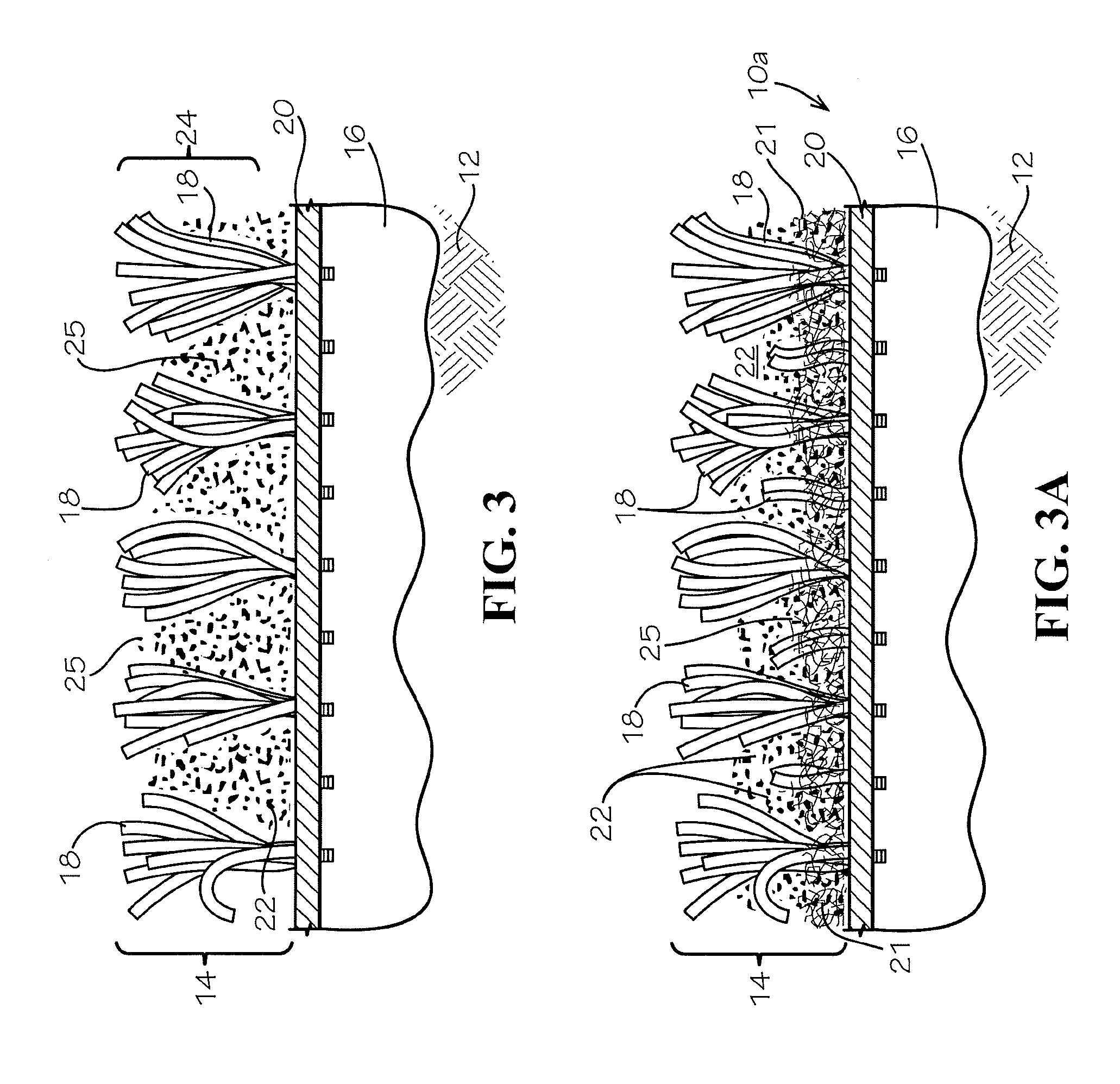
[0028] FIG. 3 illustrates a detailed view of the geotube shown in FIGS. 1 and 2 with the outer geoturf layer filled with sand and solids for providing a protective barrier above the geotextile from which the tufted blades extend.
[0029] FIG. 3A illustrates a detailed view of an alternate embodiment of a geotube with a thatch layer for holding a first sand within a matrix of a geotextile tufted with tufted tensile elements extending as simulated blades of grasses layer filled with a second sand and solids for providing a protective barrier above the geotextile from which the tufted blades extend.
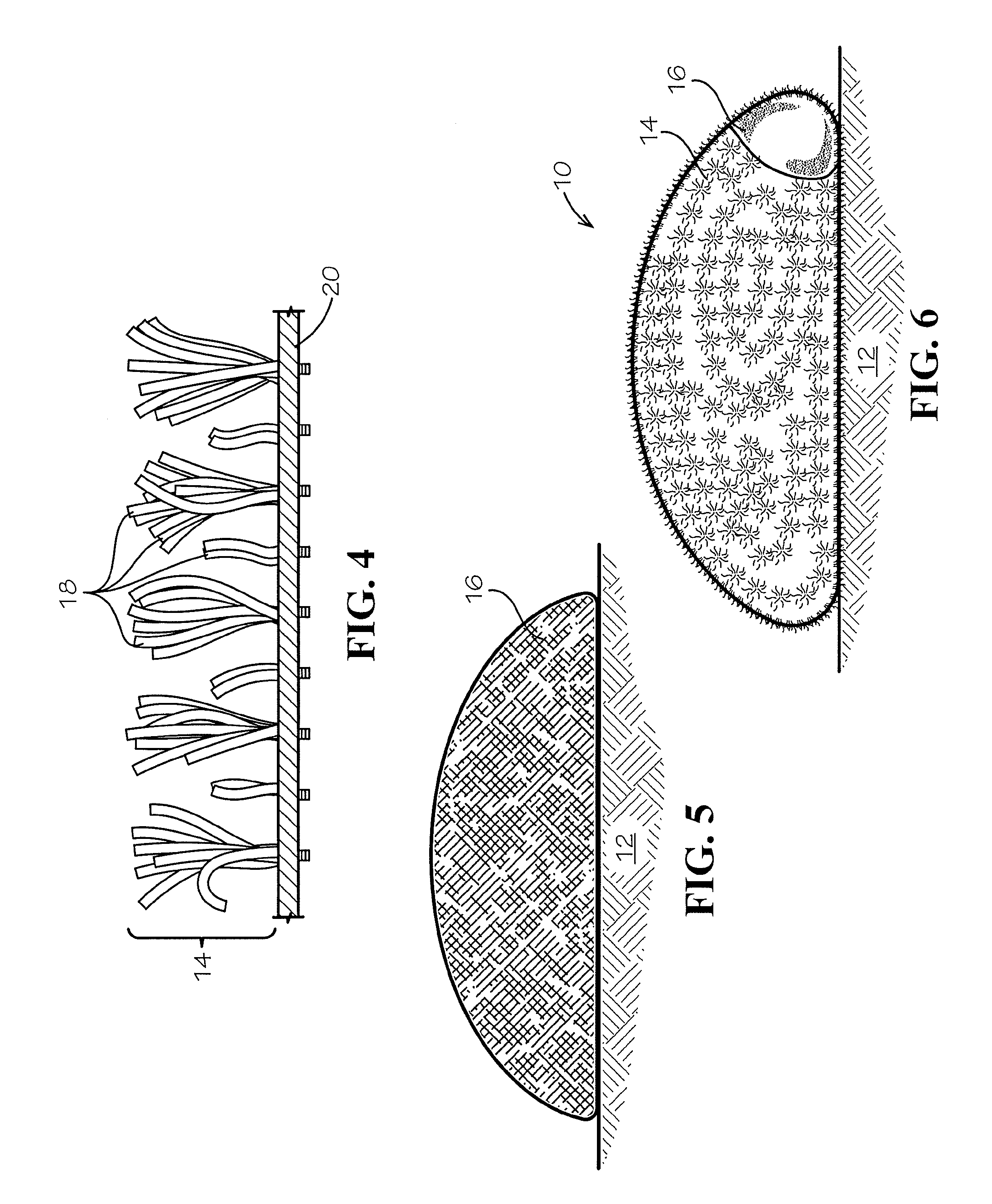
[0030] FIG. 4 illustrates a tufted geoturf cover for use with a geotube in accordance with the present invention.
[0031] FIG. 5 illustrates in cross-sectional view a geotube positioned on a beach or sand for shoreline stabilization purposes.
[0032] FIG. 6 illustrates in cross-sectional view a geotube in accordance with the present invention having a geoturf outer layer for positioning on a beach or sand for shoreline stabilization purposes.
[0033] FIG. 7 illustrates in detailed cross-sectional view the geoturf outer layer filled with sand for protecting a lower layer geotextile geotube used for shoreline stabilization purposes.
[0034] FIG. 8 illustrates a perspective view of a geotextile geotube in accordance with the present invention having a geoturf outer layer for shoreline stabilization purposes.
[0035] FIG. 9 illustrates in cross-sectional view a geotextile geotube in accordance with the present invention having a geoturf outer layer for shoreline stabilization purposes.
DETAILED DESCRIPTION
[0036] The present invention pertains to means and methods for extending the life of geotubes. Additionally, the geotube apparatus according to the present invention provides improved aesthetics and the geotube affords superior resistance to vandalism and improved UV resistance. In accordance with the present invention the geotube incorporates tufted tensile elements within and extending from the surface of the textile tube structure to act as a shield and blend-in with beach sands, coastal grass, or when coastal tubes are installed to construct offshore reefs, the synthetic grass will resemble aquatic vegetation, and to collect suspended solids such as sand carried with wave action along coastal shorelines.
[0037] The present invention is particularly described herein in reference to practice with an illustrative embodiment of shoreline and coastal erosion stabilization but is not limited to such and may be practiced for erodible surface stabilization including water shorelines, channels, streams and river shorelines, lakes and ponds, harbor linings, estuaries and shorelines, and coastal environmental areas, for surface stabilization: [0038] a. Create a newly formed geoturf tube produced in a factory wherein a tufting process incorporates a plurality of tufted tensile elements of desired width, gauge, and height into a geotube structure for placing for erodible surface stabilization; [0039] b. Place a geoturf cover above or attached to a newly installed geotube which cover is installed as a separate component to "shield" the geotube disposed for erodible surface stabilization; and [0040] c. Place a geoturf tube surface on, above, or attached to a geotube currently in erodible surface stabilization such as shoreline and coastal environmental stabilization service to "shield" and extend the life of the geotube.
[0041] The present invention may also be left exposed or may be infilled with sand, stone, glass particles, or any other natural occurring soil, dredge or aggregate or synthetic material such as glass, tire rubber, or polymeric materials suitable for the application.
[0042] Artificial turf, or synthetic turf, is a man-made surface manufactured from synthetic materials, made to look like natural grass. Synthetic turf is used as an alternative to natural grass surfaces because synthetic yarns better resist wear and severe weather and typically require less maintenance. However, synthetic turf is now being used on residential lawns and commercial applications.
[0043] Synthetic turf is also utilized in highly engineered alternatives to conventional landfill soil cover systems as identified in Ayers and Urrutia in U.S. Pat. Nos. 8,585,322; 8,403,597; and 7,682,105 and Ianniello and Rhoades U.S. Pat. No. 8,240,959. Well known prior art synthetic turf systems, such as FIELD TURF.TM., SPRINT.TM. and PROGRASS.TM., include a synthetic playing surface often coupled with rubber infill materials. These synthetic turf systems are typically installed above a natural subgrade.
[0044] The present invention relates generally to a geotube apparatus that incorporates tufted tensile elements with improved UV resistance, aesthetics, and resistance to vandalism of geotubes. The present invention utilizes tufted tensile elements as a UV shield and as a protective layer.
[0045] The present invention reflects a significant advance in coastal and shoreline stabilization apparatus and methods and particularly a departure from the prior art by providing exposed synthetic turf systems featuring operational survival over extended service life periods, such as for example, up to and beyond a decade of service life. The present invention that incorporates turf fibers for geotubes in manners non-obvious in coastal protection applications. The present invention achieves superior UV resistance over conventional tubes in that the exposed turf fibers last for over a decade. The present invention also relies upon infill (installation and in situ operational supply and replenishment) to further protect the tufted tensile elements from UV degradation. The present invention reflects a departure from the prior art for geotube application and protection. For example, the synthetic fibers utilize a sand in-fill that collects in a matrix of the geotextile and tufts of the geotube provided in a coastal application with sand transported as a suspended solid within seawater. The sand deposits and collects in the gaps or spaces between adjacent fibers of the geotextile and the tufts by wave action that transports sand. The turf fibers extending from the geoturf outer layer capture the sand and create within the matrix a protective barrier resistant to UV degradation and vandalism.
[0046] Further, the turf fibers create a rougher surface on the geotube which captures the sand particles in the turf matrix. Manning's N value is a hydraulic measure of roughness. The higher the Manning's N value the rougher the surface. Synthetic turf has a Manning's N value that typically ranges from 0.015 to 0.030 while the surface of the standard geotextile geotube will have a Manning's N value that ranges from 0.005 to 0.010. In general, a geotube with tufted tensile elements in accordance with the present invention provides an extended service life for the geotube in use for coastal and shoreline stabilization purposes.
[0047] Until the present invention, the only geosynthetic materials available for tubes were nonwoven and woven geotextiles.
[0048] The present invention relates generally to utilizing synthetic turf within the production of geotubes. The present invention includes a myriad of turfs in various lengths and colors to blend into the environment.
[0049] The present invention overcomes the many deficiencies of the conventional geotubes by providing an outer layer geotextile tufted with plurality of tufted tensile elements or grass-like blades. The increased performance attributes of the present geotube are but one desirable aspect of the present invention because such performance attributes eliminate many of the problems associated with conventional geotextiles tubes. By reducing or eliminating these problems with the present invention, the useful life of the geotube is extended.
[0050] The geotextile fabric contains the materials within the tube which are typically a soil or sand. The turf fiber forms a sand/fiber matrix barrier by containing the sand on the outside of the tube between the interspaces between adjacent tufts above the geotextile to which the turf fiber yarn tufts. For example, the tufts extend as a carpet nap of 1 inch from the geotextile and the spaced tufts define interspatial gaps. Sand (applied at installation or deposited therein by wave action during operation of the geotube for shoreline stabilization), fills the interspaces. The sand (and other water-borne particulate solids) becomes confined and trapped within the fiber turf layer, acting as a barrier for protection of the geotube.
[0051] The coating typically applied to geotubes to increase their UV resistance is a polyurethane coating. It looks and feels like an epoxy. The coating is applied to a nonwoven or woven fabric. The coating is an effective UV shield. However, the coating decreases the friction when a sand/coating/geotextile tube interface is compared to the sand/geotextile tube interface. Friction is a highly desirable property. Geotubes can be stacked. They are subjected to massive wave forces during storm events. A weak (i.e., low resistance) interface makes tubes more prone top movement, which is undesirable.
[0052] The invention also increases protection from vandalism. It is common practice to bury geotubes. Buried tubes are protected from storm events and passersby. However, once the wind or wave forces expose the tube, there is no protection. The present invention however traps sand between the tuft fibers within a vertical plane between the tube surface and the maximum length of the turf fiber. This structure provides an improved thickened barrier to vandalism and cutting of the surface of the geotube body. Attempts at vandalism is thus made very hard and time consuming. Also, graffiti would not last on the sand and fiber surface. It would wash away.
[0053] In accordance with other aspects of the present invention, synthetic turf tubes can be positioned to maximize their effectiveness. For example, tufted tensile elements can be integrated above the geotextile immediately beneath a sand layer, or exposed directly in the ocean.
[0054] Embodiments of the invention can be made in large pieces, for example, several meters wide and many meters long. Moreover, for convenience in installation, the present invention may be installed in portions which are interconnected.
[0055] The present invention can be fabricated into panels of various lengths and widths by using a means to weld, tie or sew sections to one another to form one or more continuous tubes.
[0056] The synthetic turf discussed herein includes a woven or nonwoven fabric with or without a backing and tufts on at least one surface. The tuft yarns are formed by at least one fibrillated yarn or non-fibrillated yarn together with a number of individual filament yarns, in particular with so-called monofilament or monotape yarns. The fibrillated yarn and the individual filament yarns are preferably made of polyethylene, nylon, polypropylene, polyester, or other polymeric or natural material such as jute or coconut. Other tufts may be made of a composite yarn formed by monotape yarns twisted together with a number of the monofilament yarns. The combination of a fibrillated yarn and individual filament yarns or the combination of monofilament and monotape yarns is also conceived. Another embodiment includes a thatch or non-woven within the monotape, fibrillated and filament yarns. The thatch is placed within a matrix defined by the geotextile fabric and a matrix that is intermediate the geotextile fabric and an extent plane substantially defined by the distal ends of the tufted tensile elements. This thatch or non-woven fabric captures finer sand particles while a superior portion of the matrix captures grosser or less fine sand in the gaps between adjacent tufts.
[0057] The turf tube synthetic grass surface comprises widely spaced rows of ribbons and the ribbons having a length about twice as long as the spacing between the rows of ribbons. A tufted carpet includes a primary backing having a back side and a face side, and a secondary backing. The carpet includes tufts of yarn sewn through the primary backing so as to be exposed on the face side and to form a plurality of back stitches on the back side. The yarn of the tufted carpet is a thermoplastic material. The primary and secondary backings are thermoplastic materials and are fluid-pervious fabrics. A method for making such a tufted carpet for use in a geotube includes the steps of bringing the secondary backing into contact with at least some of the back stitches on the back side of the primary backing, and heating the combination of the primary backing and the secondary backing to a temperature sufficient to adhere the secondary backing to the backstitches without melting the secondary backing.
[0058] Typical synthetic turf backing materials have relatively low tensile strength. This is because synthetic turf is typically installed on relatively flat ground and is subject to only relatively low tensile forces. A typical backing on synthetic turf may have a tensile strength as low as 100-200 pounds per foot (measured in accordance with ASTM D4595). These materials are sufficient for some geotube applications, such as geotubes that are placed entirely or partially above ground on a shoreline, that are relatively small (e.g., a few feet in diameter), and that are relatively loosely packed with sand. In such applications, the geotube may be formed solely from the synthetic turf itself with no geotextiles. In other applications, geotubes are subjected to significant forces. For example, a geotube may be of a large diameter (e.g., 30 feet) and may be submerged under water near a shoreline. Such geotubes are subject to significant forces exerted on them by movement of seawater. In such applications, the geotube may be formed from a geotextile that encompasses the sand with synthetic turf around the outside of the geotube and adhered to the geotextile by sewing, adhesive bonding, heat-bonding or other means. Such geotextiles typically have a tensile strength in excess of 1000 pounds per foot (measured in accordance with ASTM D4595). In yet other embodiments, the synthetic turf may be formed using a single geotextile as a backing material, with or without additional backing layers.
[0059] By choosing one or more shapes, sizes, colors, UV additives, alternative embodiments of the present invention can be provided. For example, the present invention may have turf fibers ranging from 1/4 inch to 4 inches wherein the synthetic turf is designed to resemble aquatic vegetation and retain 50% or greater of specified strength at 5,000 hours of UV exposure measured in accordance with ASTM D 4355 (ISO 4892-2) or 50% or greater of specified strength at 7,500 hours of UV exposure measured in accordance with ASTM D 7238 (ISO 4892-3). Other UV exposure and natural exposure testing is measured in accordance with ASTM G147 and G7.
[0060] The polymeric turf fibers include one or more ultraviolet inhibitors or absorbers such as benzophenone, benzotriazole, Hindered Amines Light Stabilizers (HALS), carbon black, or UV blockers titanium dioxide and/or zinc oxide.
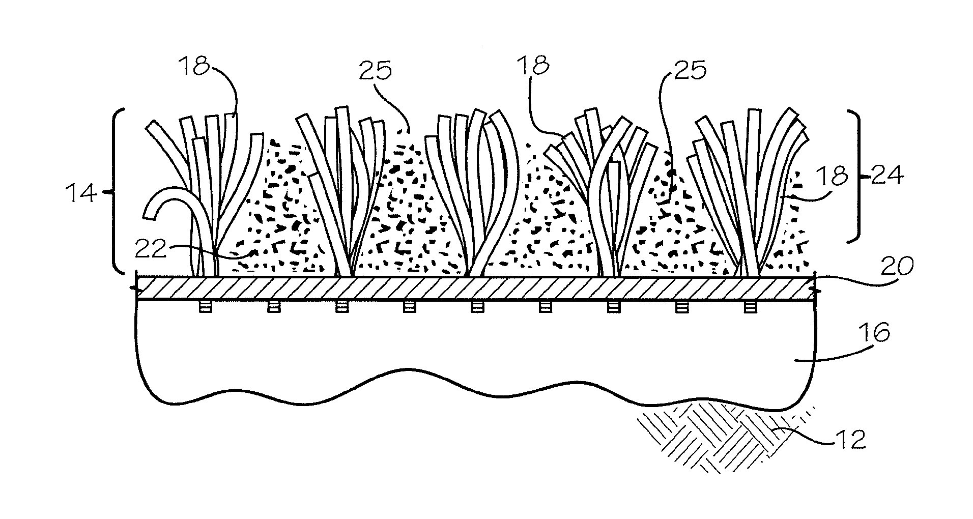
[0061] With reference to the drawings, in which like parts have like identifiers, FIG. 1 illustrates a detailed cut-away view of a geotube 10 placed on a shoreline or a beach 12 with a geoturf layer 14 covering in accordance with the present invention. The geotube 10 includes a body 16 formed with woven or non-woven textiles and sewn into an elongated tube or cylinder. As best illustrated in cross-sectional view in FIG. 9, the geotube 10 has a dimensional width 11 extending between opposing sides and a dimensional height 13 between a bottom that contacts the beach or soil surface and an upper extent. The geotube 10 being formed with a textile body 16 that is flexible defines a generally dome-shaped container sitting on the beach 12. With continuing reference to FIG. 1, the geoturf layer 14 attaches to an outer surface of the geotube body 16. A plurality of spaced-apart tufts 18 tuft to and extend from the geoturf layer. In the illustrated embodiment, the geoturf layer 14 includes a geotextile 20 of a woven textile material tufted with synthetic yarns or strands as a matrix of the spaced-apart tufts 18 and which has the appearance of grass. The spacing of the tufts 18 defines interspatial gaps or spaces 22.
[0062] FIG. 2 illustrates a detailed view of the geotube 10 shown in FIG. 1 during operation for shoreline stabilization purposes. Seawater generally 26 with waves provide periodic overflow water such as ebb and flow that overflows the geotube 10. The waves carry sand and suspended solids generally 25. The outer geoturf layer 14 fills with the carried sand and solids 25 which are captured in situ by the turf blades 18 and fill and replenish the interspatial gaps 22. Further, during installation of the geotube 10, the gaps 22 may initially be supplied with sand and solids for commencing shoreline stabilization.
[0063] FIG. 3 illustrates a detailed view of the geotube 10 shown in FIGS. 1 and 2 with the outer geoturf layer 14 in which the interspatial gaps 22 are filled with the captured sand and solids for providing a protective barrier above the geotextile 20 from which the tufted blades 18 extend and forms a thickened protective barrier for the geotube body 16. The gaps 22 may be filled with sand during installation construction or deposited in situ with sands carried by water such as wave action, water flow, or alternatively, mechanical hydraulic distribution devices.
[0064] FIG. 3A illustrates a detailed view of an alternate embodiment of a geotube 10a includes a thatch layer 21. The thatch layer 21 extends from an upper surface of the geotextile sheet 14 to a thatch extent intermediate the geotextile fabric and an extent plane substantially defined by the distal ends of the tufted tensile elements. The thatch layer 21 provides a finer sieve for holding a first sand within a first portion of the matrix of the geotextile sheet 14 tufted with the tufted tensile elements 18, and a second portion from the thatch layer 21 to the extent plane, which second portion fills with a second sand and solids for providing a protective barrier above the geotextile from which the tufted blades extend. The first sand collected within the thatch layer 21 is finer than the second sand. As discussed below, the geotube of the present invention operates in a shoreline or coastal stabilization application. The wave action provides for in situ filling, and operational maintenance, of the sand in-fill in the first and second portions.
[0065] The geotube 10a includes a geotextile sheet 14a as a multilayer of the geotextile 20 and the thatch layer 21. In the illustrated embodiment, the thatch layer 21 attaches to the geotextile 20 by the tufting of the yarns to form the tufted blades 18. The thatch layer 21 may be a non-woven blanket. The tufted blades 18 extend from the geotextile sheet 14 and spaced-apart define the interspatial gaps 22. In an alternate embodiment, the thatch layer 21 comprises an airlay fabric having a plurality of interspatial gaps that capture sand, soil or particles such as suspended carry in water. In yet another alternate embodiment, the thatch layer 21 comprises a fabric formed of multiple yarns, such as texturized yarns, crimped yarns, or heat-set yarns.
[0066] FIG. 4 illustrates a tufted geoturf cover 14 for use in accordance with the present invention with a geotube body previously installed on a shoreline or beach. The tufted geoturf cover 14 may overlie a previously installed geotube body 16. Attachments such as adhesive, ground anchors, or the like fasteners may be used to secure the geoturf cover to the geotube body.
[0067] FIG. 5 illustrates in cross-sectional view a geotube body 16 positioned on a beach or sand 12 for shoreline stabilization purposes. The geotube body 16 is an elongated textile cylinder filled with ballast or a weighting material such as sand or dredge material pumped into the geotube body during installation.
[0068] FIG. 6 illustrates in cross-sectional view the geotube 10 in accordance with the present invention having the geoturf outer layer 14 for positioning on the beach or sand shore 12 for shoreline stabilization purposes. Waves and currents flow as indicated by the arrow over the geotube 10 and sand and suspended solids therein deposit in and fill and replenish sand and solids in the gaps 22 between the tufts 18 to form a sand/solids/tufts thickened barrier above the geotextile 20 and thereby a protective barrier for the geotube body 16 (shown in cut-away detail).
[0069] FIG. 7 illustrates in detailed cross-sectional view the geotube 10 with the geoturf outer layer 14 filled with sand and solids as the thickened protecting barrier generally 24 for the lower geotextile 20 and the geotextile forming the geotube body 16 for the geotube 10 used for shoreline stabilization purposes. The infill sand and solids typically fill the gaps 22 to about the extent of the distal free ends of the tufts 18. It is to be appreciated that some solids such as broken shells and sticks may extend above the distal ends of the tufts 18 (not illustrated). The protective layer 24 may be infilled with sand particles during installation construction or deposited with suspended sands and particles by water, such as waves, flowing water, hydraulic mechanical distribution devices. For example, after the geoturf 14 is placed to overlay the geotube body 16 remote from a high tide line on a shoreline, a mechanical hydraulic sprayer may overspray the geoturf 14 with an aqueous sand mixture for building the barrier layer thereon.
[0070] FIG. 8 illustrates a perspective view of a geotextile geotube 10 installed on the beach in accordance with the present invention having a geoturf outer layer 14 overlying the geotube body 16 (shown in cut-away) for shoreline stabilization purposes.
[0071] FIG. 9 illustrates in cross-sectional view the geotextile geotube 10 in accordance with the present invention having the geoturf outer layer 14 with tufts 18 defining gaps 22 that receive sand and suspended solids forming the barrier 24, for shoreline stabilization purposes while protecting the geotube body 16 from exposure damage and vandalism. Wave action from water 26 carries sand and suspended solids over the geotube 10. The tufts 18 and gaps 22 cooperatively capture the sand and suspended solids that fill and replenish the protective barrier 24 in situ for protection of the geotextile 20 and the geotube body 16 (shown in cut-away detail). The protective barrier 24 typically has a thickness of at least 0.1 inch and may extend to a depth of substantially most of the height of the elongated blades 18 in the tufts.
[0072] With reference to FIGS. 1-3, the geotube 10 of the present invention operates for ground surface environmental stabilization, and more particularly illustrated in FIGS. 9 and 10 for shoreline and coastal environmental stabilization and enhancing growth of grasses on sand berms proximate ocean coastal shorelines. The elongated geotube 10 is placed on the ground surface, such a portion of a beach proximate a coastal area of an ocean. The flexible body 16 is filled with sand, such as communicating an aqueous mixture of water and sand, which carrier water flows outwardly of while the sand being contained therein defines the generally dome-shaped container. A plurality of the geotubes may be disposed in spaced relation to define a series of mounds and/or linearly in an arcuate line along the shoreline. Seawater waves ebb and flow to overflow over and around the geotube 10. As illustrated in FIG. 2, the outer geoturf layer 14 fills with the sand and solids 25 carried by the waves, which sand and solids are captured in situ by the turf blades 18 and fill and replenish the interspatial gaps 22. As shown in FIG. 3, the captured sand and solids 25 form the protective barrier above the geotextile 20 and cooperatively with the elongated tuft blades 18 forms the thickened protective barrier for the geotube body 16.
[0073] Similarly with the alternate embodiment of the geotube 10a illustrated in FIG. 3A, the ebb and flow of the seawater waves carries sands of various finess over and around the geotube. The thatch layer 21 captures finer sands while the adjacent tuft blades 18 capture in the gaps 22 the grosser sands. The recurring wave action provides for in situ filling, and operational maintenance, of the sand in-fill in the first and second portions.
[0074] Alternatively, the tufted geoturf cover 20 as shown in FIG. 4 readily installs as a separate overlying apparatus to a geotube body (shown in FIG. 5), which geotube body is installed proximately concurrently or installed onto an existing previously installed geotube body. The tufted geoturf cover attached to the geotube body as shown in FIG. 6 operates for shoreline and coastal environmental stabilization with wave action that ebbs and flows over and around the cover. As shown in FIG. 7, the spaced tufted blades 18 capture in the gaps 22 of the matrix the sands carried in the seawater waves. Thus, the tufted geoturf cover 14 supplements long-installed geotube berms for extending the useful service life for coastal stabilization projects.
[0075] Alternatively, the tufted tensile elements 18 are tufted, sewn, laminated, calendared, welded, adhesively applied, mechanically attached to an underlying permeable geotextile sheet that is subsequently formed into a tube-like structure, or any combination of attaching the tufted tensile elements thereto, for a geotube with improved performance and service life in accordance with the present invention.
[0076] The foregoing discloses embodiments of a geoturf tube and a geoturf cover that provide improved erodible surface stabilization in illustrative disclosure as to coastal and shoreline stabilization applications but not limited to such, and as to particular embodiments, provide stabilization structures having high resistance to UV degradation and to vandalism. The foregoing discloses the construction of such apparatus by combining a plurality (for example but not limiting of one to three layers) of geotextiles and spaced-apart plurality of tufts that extend as synthetic grasses. The geotubes and geoturf tufted covers of the present invention are selectively constructed and arranged to meet specified performance characteristics for stabilization service life longevity and resistance to ultraviolet degradation. While this invention has been described with particular reference to certain embodiments, one of ordinary skill may appreciate that variations and modifications can be made without departing from the spirit and scope of the invention as recited in the appended claims.
* * * * *
D00000
D00001
D00002
D00003
D00004
XML
uspto.report is an independent third-party trademark research tool that is not affiliated, endorsed, or sponsored by the United States Patent and Trademark Office (USPTO) or any other governmental organization. The information provided by uspto.report is based on publicly available data at the time of writing and is intended for informational purposes only.
While we strive to provide accurate and up-to-date information, we do not guarantee the accuracy, completeness, reliability, or suitability of the information displayed on this site. The use of this site is at your own risk. Any reliance you place on such information is therefore strictly at your own risk.
All official trademark data, including owner information, should be verified by visiting the official USPTO website at www.uspto.gov. This site is not intended to replace professional legal advice and should not be used as a substitute for consulting with a legal professional who is knowledgeable about trademark law.