Carbonatable Calcium Silicate Compositions And Methods Thereof
Atakan; Vahit ; et al.
U.S. patent application number 16/194685 was filed with the patent office on 2019-05-23 for carbonatable calcium silicate compositions and methods thereof. The applicant listed for this patent is Solidia Technologies, Inc.. Invention is credited to Vahit Atakan, Nicholas DeCristofaro, Sean Quinn, Deepak Ravikumar, Sadananda Sahu.
| Application Number | 20190152856 16/194685 |
| Document ID | / |
| Family ID | 55179306 |
| Filed Date | 2019-05-23 |


View All Diagrams
| United States Patent Application | 20190152856 |
| Kind Code | A1 |
| Atakan; Vahit ; et al. | May 23, 2019 |
CARBONATABLE CALCIUM SILICATE COMPOSITIONS AND METHODS THEREOF
Abstract
The invention provides novel carbonatable calcium silicate compositions and carbonatable calcium silicate phases that are made from widely available, low cost raw materials by a process suitable for large-scale production. The method of the invention is flexible in equipment and production requirements and is readily adaptable to manufacturing facilities of conventional cement. The invention offers an exceptional capability to permanently and safely sequesters CO.sub.2.
| Inventors: | Atakan; Vahit; (West Windsor, NJ) ; Quinn; Sean; (Piscataway, NJ) ; Sahu; Sadananda; (Piscataway, NJ) ; Ravikumar; Deepak; (Piscataway, NJ) ; DeCristofaro; Nicholas; (Piscataway, NJ) | ||||||||||
| Applicant: |
|
||||||||||
|---|---|---|---|---|---|---|---|---|---|---|---|
| Family ID: | 55179306 | ||||||||||
| Appl. No.: | 16/194685 | ||||||||||
| Filed: | November 19, 2018 |
Related U.S. Patent Documents
| Application Number | Filing Date | Patent Number | ||
|---|---|---|---|---|
| 14817193 | Aug 3, 2015 | 10173927 | ||
| 16194685 | ||||
| 62032862 | Aug 4, 2014 | |||
| Current U.S. Class: | 1/1 |
| Current CPC Class: | C04B 28/10 20130101; Y02P 40/10 20151101; C04B 7/3453 20130101; Y02P 40/18 20151101; C04B 28/188 20130101; C04B 7/345 20130101; Y02P 40/148 20151101; C04B 28/10 20130101; C04B 40/0231 20130101; C04B 28/188 20130101; C04B 40/0231 20130101 |
| International Class: | C04B 28/18 20060101 C04B028/18; C04B 7/345 20060101 C04B007/345; C04B 28/10 20060101 C04B028/10 |
Claims
1-22. (canceled)
23. A carbonatable calcium silicate composition in powder form having a mean particle size (d50) of about 8 .mu.m to about 25 .mu.m, with 10% of particles (d10) sized below about 0.1 .mu.m to about 3 .mu.m, and 90% of particles (d90) sized above about 35 .mu.m to about 100 .mu.m, wherein the composition comprises: calcium silicate in the form of one or more discrete crystalline calcium silicate phases selected from CS (wollastonite or pseudowollastonite), C3S2(rankinite), and C2S (belite, larnite, bredigite), and calcium silicate in the form of an amorphous calcium silicate phase, wherein the one or more discrete crystalline calcium silicate phases are present at about 30% or more by mass of the total phases; elemental Ca and elemental Si are present in the composition at a molar ratio from about 0.8 to about 1.2; and metal oxides of Al, Fe and Mg are present in the composition at about 30% or less by mass, wherein the composition is carbonatable with CO.sub.2 at a temperature of about 30.degree. C. to about 90.degree. C. to form CaCO.sub.3 with a mass gain of about 10% or more.
24. The carbonatable composition of claim 23, wherein the ratio of d90:d10 is about 5 to about 1,000.
25. The carbonatable composition of claim 23, wherein the ratio of d50:d10 is about 2 to about 250.
26. The carbonatable composition of claim 23, wherein the ratio of d90:d50 is about 2 to about 15.
27. (canceled)
28. The carbonatable composition of claim 23, comprising one or more residual SiO.sub.2 and CaO phases.
29. The carbonatable composition of claim 23, comprising one or more melilite type phases having the general formula (Ca,Na,K).sub.2[(Mg, Fe.sup.2+,Fe.sup.3+,Al,Si).sub.3O.sub.7] or ferrite type phases having the general formula Ca.sub.2(Al,Fe.sup.3+).sub.2O.sub.5.
30. The carbonatable composition of claim 23, wherein the composition comprises calcium silicate phases existing in an amorphous state and calcium silicate phases existing in a crystalline state.
31. The carbonatable composition of claim 23, wherein the molar ratio of elemental Ca to elemental Si is from about 0.90 to about 1.10.
32. The carbonatable composition of claim 23, comprising about 25% or less of metal oxides of Al, Fe and Mg by total oxide mass.
33. The carbonatable composition of claim 23, wherein CS is present at about 10 wt % to about 60 wt %, C3S2 in about 5 wt % to 50 wt %, C2S in about 5 wt % to 60 wt %, and CaO in about 0 wt % to 3 wt %.
34. The carbonatable composition of claim 33, wherein CS is present at about 20 wt % to about 60 wt %, C3S2 in about 10 wt % to 50 wt %, C2S in about 10 wt % to 50 wt % and C CaO in about 0 wt % to 3 wt %.
35. A carbonated material produced from the carbonatable calcium silicate composition of claim 23 via carbonation at a temperature of about 30.degree. C. to about 90.degree. C.
Description
PRIORITY CLAIMS AND RELATED PATENT APPLICATIONS
[0001] This application claims the benefit of priority from U.S. Provisional Application Ser. No. 62/032,862 filed on Aug. 4, 2014, the entire content of which is incorporated herein by reference in its entirety.
FIELD OF THE INVENTION
[0002] The invention generally relates to calcium silicate compositions. More particularly, the invention relates to novel carbonatable calcium silicate compositions and phases, and methods for their manufacture and use. These calcium silicate compositions and phases are suitable for use as non-hydraulic cement that hardens by a carbonation process. They may be applied in a variety of concrete components in the infrastructure, construction, pavement and landscaping industries.
BACKGROUND OF THE INVENTION
[0003] Concrete is the most consumed man-made material in the world. A typical concrete is made by mixing Portland cement, water and aggregates such as sand and crushed stone. Portland cement is a synthetic material made by burning a mixture of ground limestone and clay, or materials of similar composition in a rotary kiln at a sintering temperature of 1450.degree. C. Portland cement manufacturing is not only an energy-intensive process, but one which releases considerable quantities of greenhouse gas (CO.sub.2). The cement industry accounts for approximately 5% of global anthropogenic CO.sub.2 emissions. More than 60% of this CO.sub.2 comes from the chemical decomposition, or calcination of limestone.
[0004] There has been growing effort to reduce total CO.sub.2 emissions within the cement industry. According to a proposal by the International Energy Agency, the cement industry needs to reduce its CO.sub.2 emissions from 2.0 Gt in 2007 to 1.55 Gt by 2050. This represents a daunting task because, over this same period, cement production is projected to grow from 2.6 Gt to 4.4 Gt.
[0005] To meet this formidable challenge, a revolutionary approach to cement production is required that significantly reduces the energy requirement and CO.sub.2 emissions of a cement plant. Ideally, the new approach preferably offers the ability to permanently and safely sequester CO.sub.2 while being adaptable and flexible in equipment and production requirements, allowing manufacturers of conventional cement to easily convert to the new platform.
SUMMARY OF THE INVENTION
[0006] The calcium silicate compositions of the invention provide a foundation for a revolutionary approach to cement production that significantly reduces the energy requirement and CO.sub.2 emissions. The disclosed carbonatable calcium silicate compositions are made from widely available, low cost raw materials by a process suitable for large-scale production. The method of the invention is flexible in equipment and production requirements and is readily adaptable to manufacturing facilities of conventional cement. The unique approach also offers an exceptional capability to permanently and safely sequester CO.sub.2.
[0007] These calcium silicate compositions can be used in a variety of concrete applications such as in construction, pavements and landscaping, and infrastructure with reduced equipment need, improved energy consumption, and more desirable carbon footprint.
[0008] In one aspect, the invention generally relates to the calcium silicate compositions and their chemistry. The composition includes various calcium silicates. The molar ratio of elemental Ca to elemental Si in the composition is from about 0.8 to about 1.2. The compositions may also include metal oxides of Al, Fe, Mg constituting about 30% or less by total oxide mass. The calcium silicate composition comprises a blend of discrete calcium silicate phases, selected from one or more of CS (wollastonite or pseudowollastonite), C3S2 (rankinite), C2S (belite or lamite or bredigite) and a calcium-silicate based amorphous phase comprising about 30% or more of the total phases. The amorphous phase may additionally incorporate Al, Fe and Mg ions and other impurity or trace ions present in the raw materials. Each of these calcium silicate phases is suitable for carbonation with CO.sub.2.
[0009] The calcium silicate compositions may also include small quantities of residual CaO (lime) and SiO.sub.2 (silica).
[0010] The calcium silicate composition may also include small quantities of C3S (alite, Ca.sub.3SiO.sub.5).
[0011] The C2S phase present within the calcium silicate composition may exist as (Ca.sub.7Mg(SiO.sub.4).sub.4) (bredigite) or as any of .alpha.-Ca.sub.2SiO.sub.4, .beta.-Ca.sub.2SiO.sub.4 or .gamma.-Ca.sub.2SiO.sub.4 polymorph or combination thereof.
[0012] The calcium silicate compositions may also include quantities of inert phases (i.e., non-carbonatable under typical carbonation conditions) such as melilite type minerals (melilite or gehlenite or akermanite) with the general formula (Ca,Na,K).sub.2[(Mg, Fe.sup.2+,Fe.sup.3+,Al,Si).sub.3O.sub.7] and ferrite type minerals (ferrite or brownmillerite or C4AF) with the general formula Ca.sub.2(Al,Fe.sup.3+).sub.2O.sub.5.
[0013] The calcium silicate composition is suitable for carbonation with CO.sub.2 at a temperature of about 30.degree. C. to about 90.degree. C. to form CaCO.sub.3 with mass gain of about 10% or more.
[0014] In another aspect, the invention generally relates to a carbonatable calcium silicate composition in powder form having a mean particle size (d50) of about 8 .mu.m to about 25 .mu.m, with 10% of particles (d10) sized below about 0.1 .mu.m to about 3 .mu.m, and 90% of particles (d90) sized above about 35 .mu.m to about 100 .mu.m.
[0015] In yet another aspect, the invention generally relates to a carbonated material that is produced from a calcium silicate composition disclosed herein.
BRIEF DESCRIPTION OF THE DRAWINGS
[0016] The objects and features of the invention can be better understood with reference to the drawings described below, and the claims. The drawings are not necessarily to scale, emphasis instead generally being placed upon illustrating the principles of the invention. In the drawings, like numerals are used to indicate like parts throughout the various views.
[0017] FIG. 1 is a pressure-temperature phase diagram showing the phases present in the reversible reaction CaCO.sub.3+SiO.sub.2CaSiO.sub.3 (calcium silicate)+CO.sub.2.
[0018] FIG. 2 is a pressure-temperature phase diagram showing the phases present in the reversible reaction 3CaCO.sub.3+2CaSiO.sub.32Ca.sub.2SiO.sub.4.CaCO.sub.3+CO.sub.2.
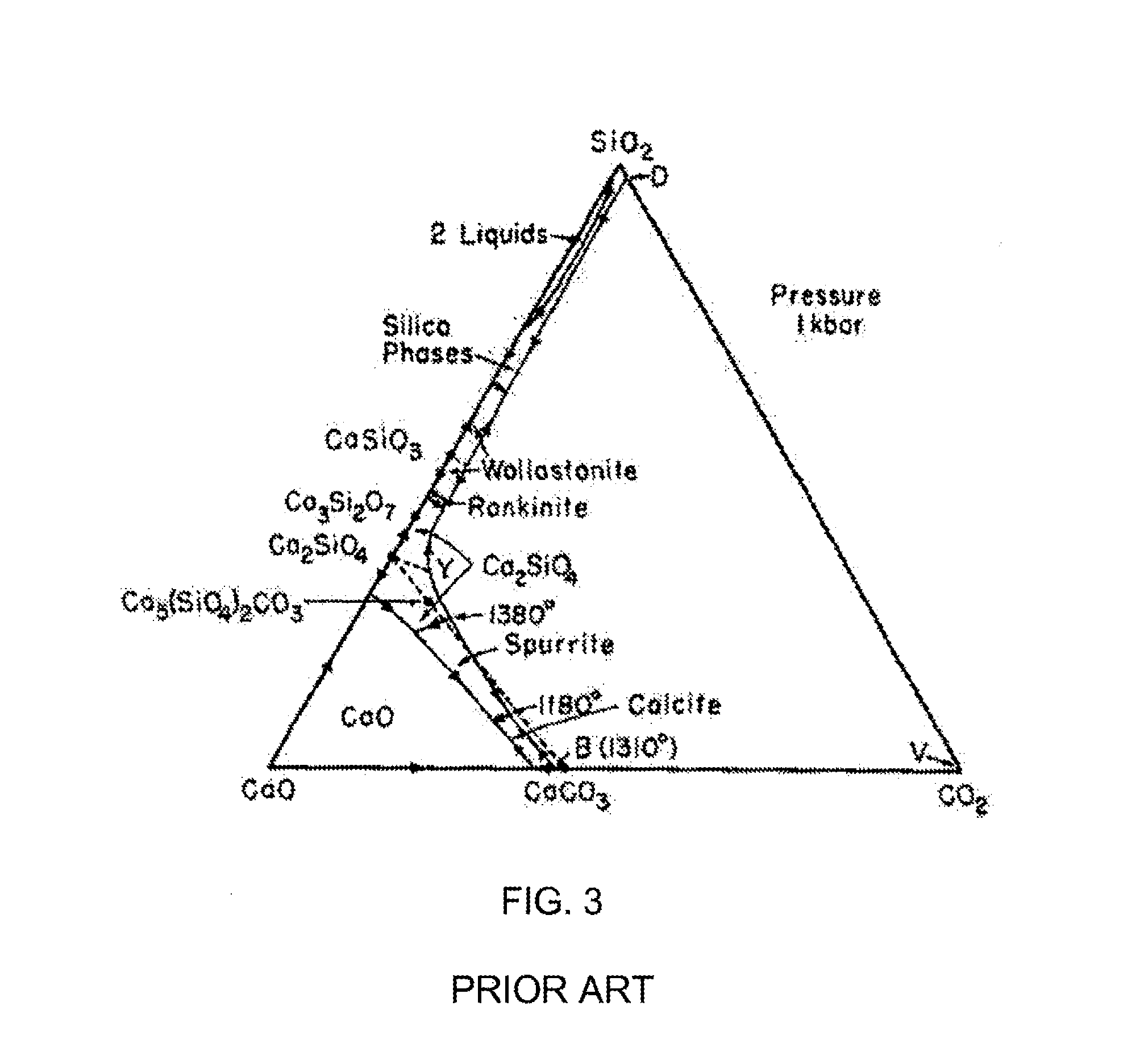
[0019] FIG. 3 is a phase diagram of the CaO--SiO.sub.2--CO.sub.2 system at a pressure of 1 kilobar.
[0020] FIG. 4 is a pressure-temperature phase diagram showing the phases present in the reversible reaction MgO+CO.sub.2MgCO.sub.3.
[0021] FIG. 5 is a pressure-temperature phase diagram showing the equilibrium curves for the reversible reaction MgO+CO.sub.2MgCO.sub.3 as a function of the proportion of CO.sub.2 in an inert gas.
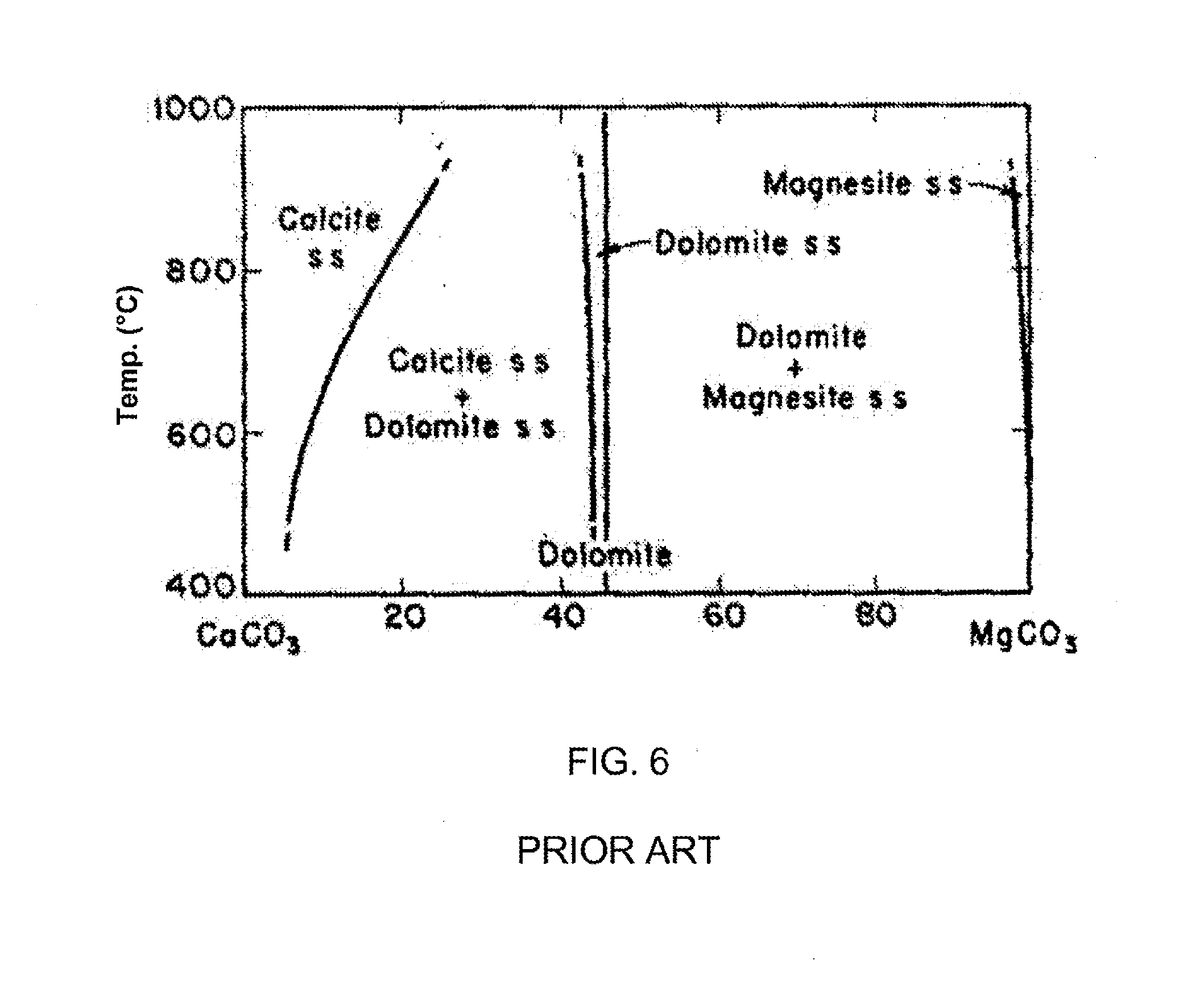
[0022] FIG. 6 is a temperature-composition phase diagram that illustrates the stability regions for various phases in the CaCO.sub.3--MgCO.sub.3 system.
[0023] FIG. 7 is a tetrahedron diagram illustrating the phase relationships among the compounds CaO, MgO, SiO.sub.2 and CO.sub.2, and showing the CO.sub.2 deficient region below the Cc-Di-Wo and the Cc-Wo-Mo planes (shaded), where Cc denotes calcite, Wo denotes Wollastonite, Ak denotes Akermanite, Di denotes diopside, and Mo denotes monticellite (CaMgSiO.sub.4).
[0024] FIG. 8 is a pressure-temperature phase diagram illustrating the phase relationships among the compounds CaO, MgO, SiO.sub.2 and CO.sub.2, with univariant curves emanating from the quaternary invariant point involving the phases calcite (Cc), diopside (Di), forsterite (Fo), monticellite (Mo), Akermanite (Ak), and CO.sub.2. The inset is the phase diagram for the three compound systems of CaCO.sub.3, MgO and SiO.sub.2.
[0025] FIG. 9 is a schematic diagram of a CO.sub.2 composite material curing chamber that provides humidification according to principles of the invention.
[0026] FIG. 10 is a schematic diagram of a curing chamber with multiple methods of humidity control as well as ability to control and replenish CO.sub.2 using constant flow or pressure regulation and that can control the temperature according to principles of the invention.
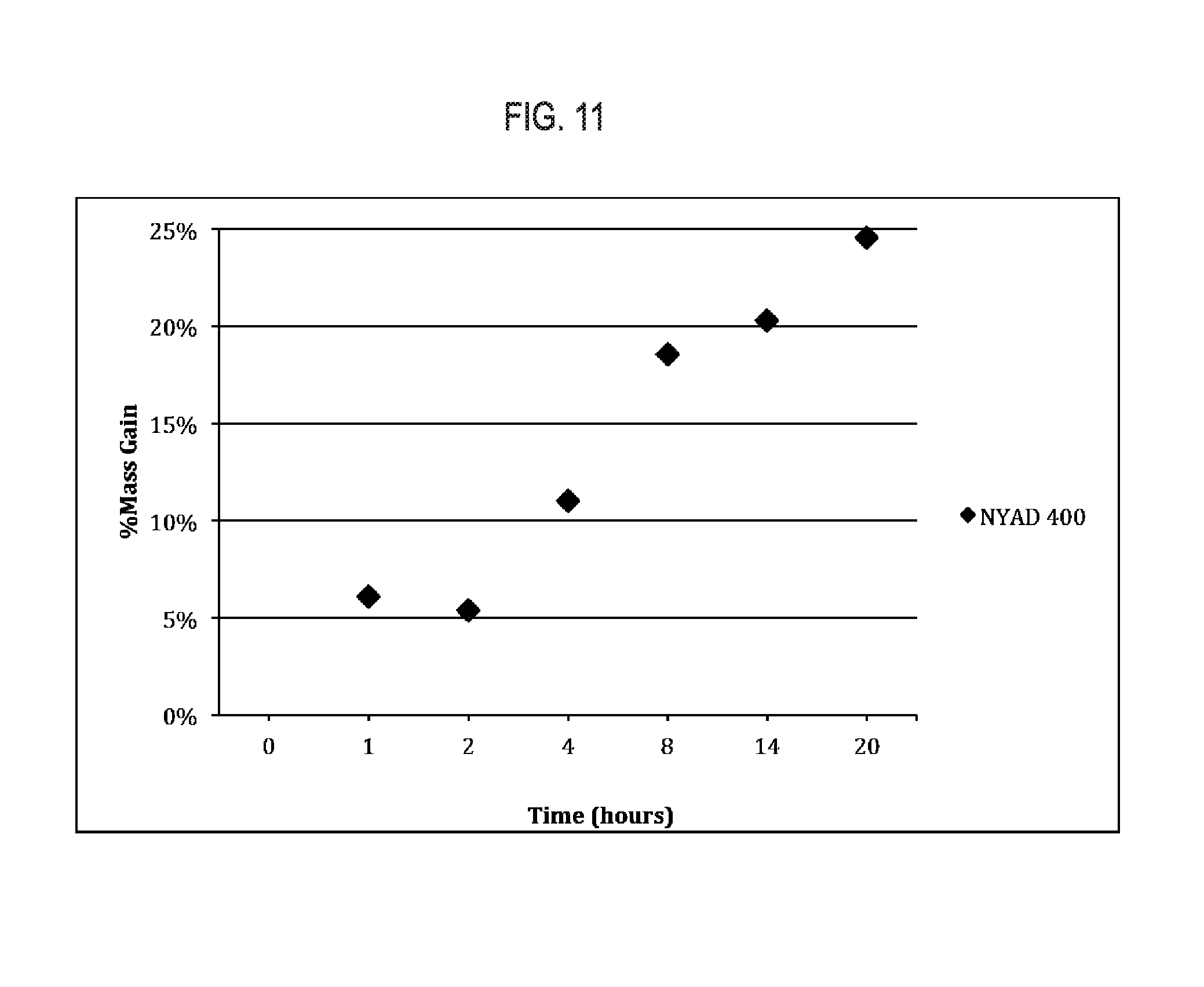
[0027] FIG. 11 shows exemplary results regarding mass gain of NYAD 400 mineral wollastonite following a 60.degree. C. reaction with CO.sub.2.
[0028] FIG. 12 shows exemplary results regarding mass gain of some rotary kiln sample material following a 60.degree. C. reaction with CO.sub.2. The mass gain at 0 hours indicates the mass gain after wetting the powder, due to the hydration of free lime.
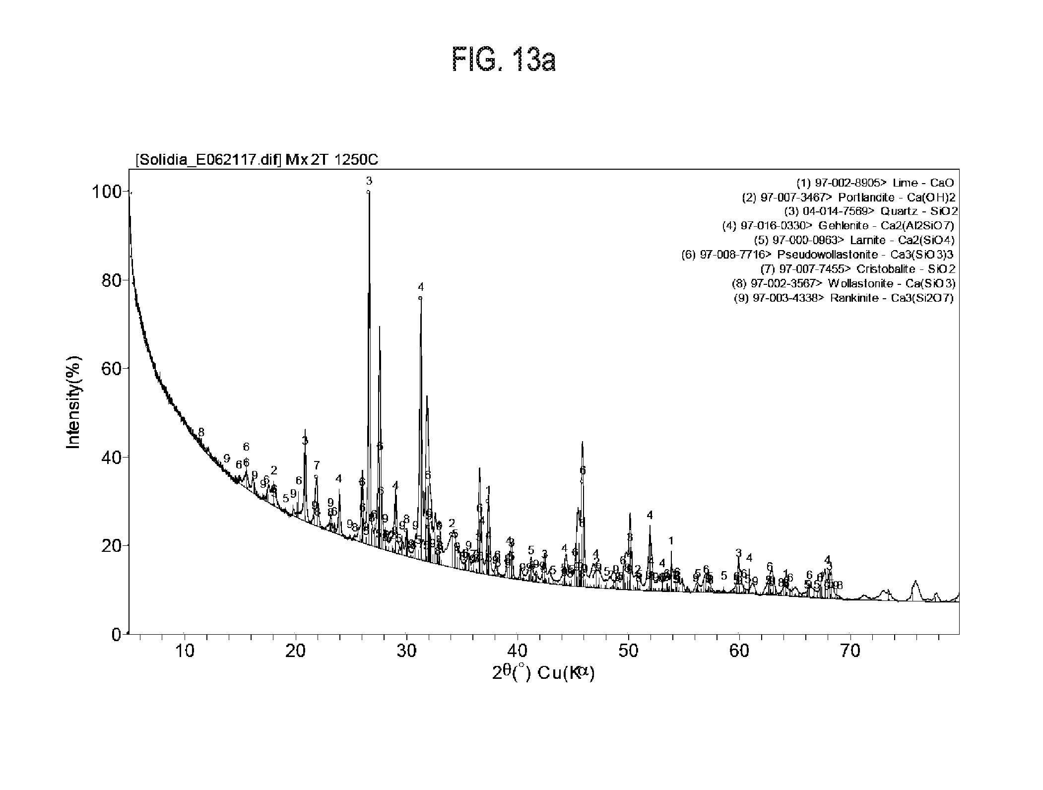
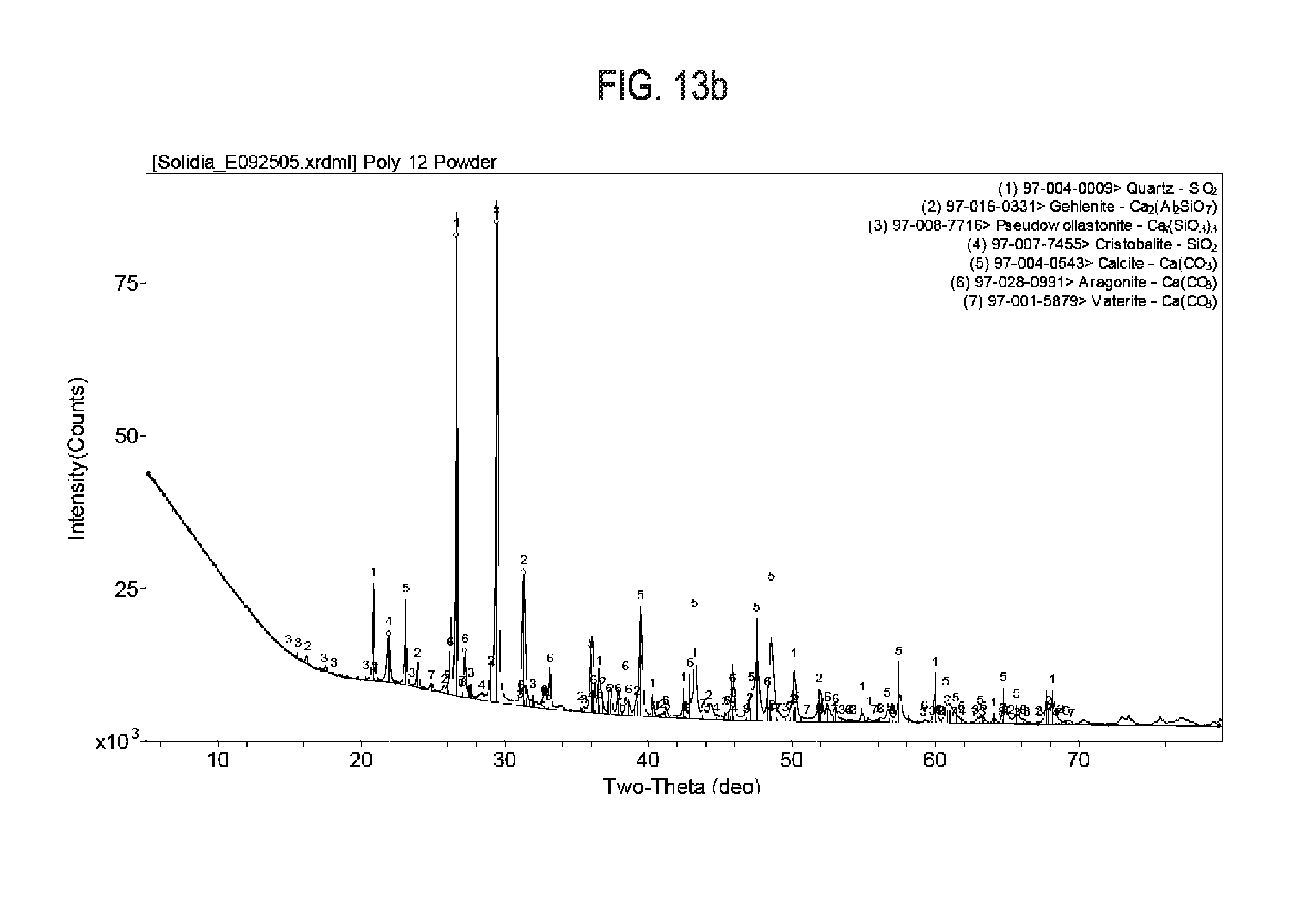
[0029] FIG. 13a shows exemplary results regarding X-Ray diffraction data and crystallographic peaks used for Reitveld refinement, as is cement sample 12.
[0030] FIG. 13b shows exemplary results regarding X-Ray diffraction data and crystallographic peaks used for Reitveld refinement, as is cement sample 12 after a 20 hour carbonation at 60.degree. C.
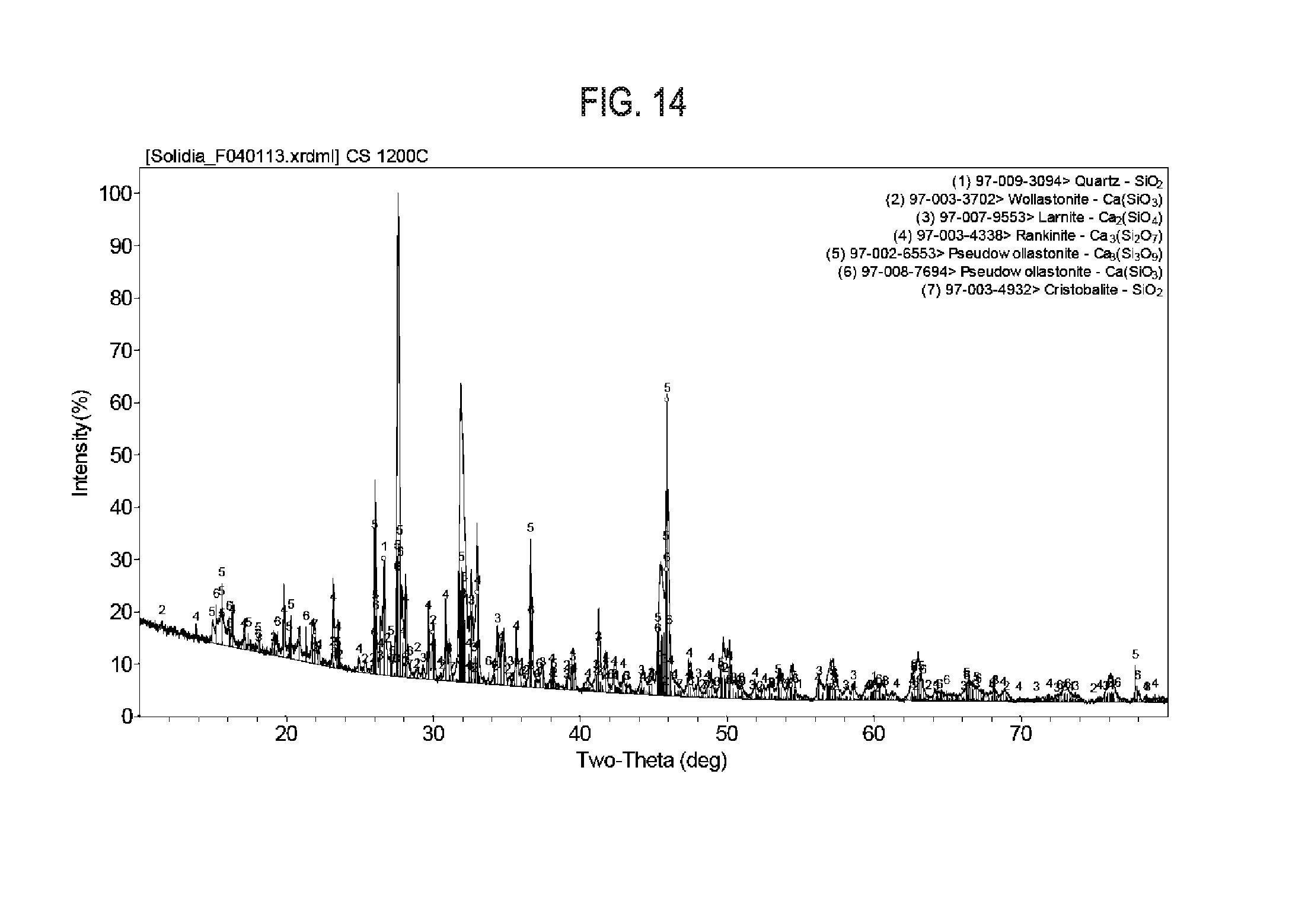
[0031] FIG. 14 shows exemplary results regarding X-Ray diffraction pattern and associated crystallographic peaks of calcium silicates phases produced from high purity chemicals in a box furnace.
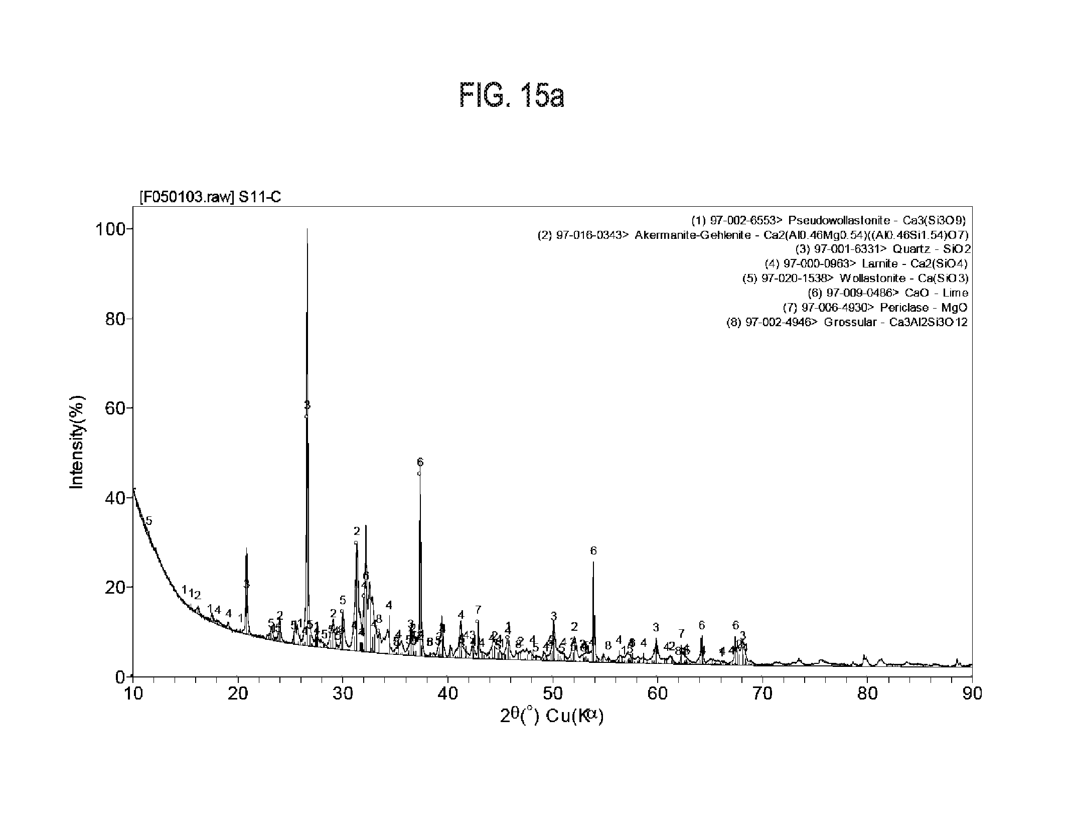
[0032] FIG. 15a shows exemplary results regarding X-Ray diffraction pattern of siliceous limestone calcined at 1,000.degree. C.
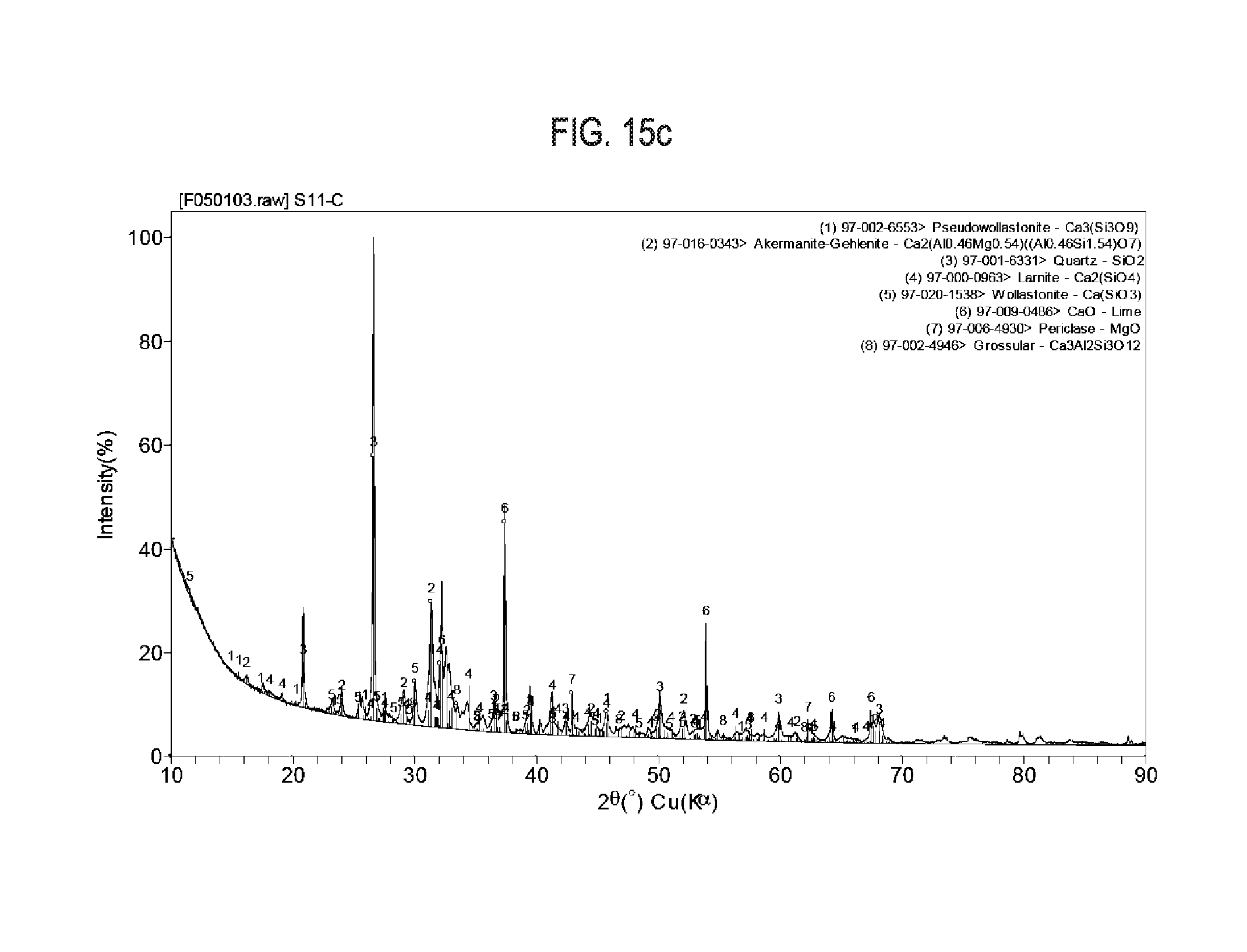
[0033] FIG. 15b shows exemplary results regarding X-Ray diffraction pattern of siliceous limestone calcined at 1,100.degree. C.
[0034] FIG. 15c shows exemplary results regarding X-Ray diffraction pattern of siliceous limestone calcined at 1,200.degree. C.
[0035] FIG. 16 shows exemplary results regarding synthetic high temperature wollastonite cement. The X-Ray diffraction pattern indicates that the material is primarily amorphous in structure.
[0036] FIG. 17 shows exemplary results regarding X-Ray diffraction spectrum of a synthetic wollastonite glass (bottom) and the same sample\after CO.sub.2 curing at 60.degree. C. (top).
[0037] FIG. 18 shows exemplary particle size distribution of jet milled exemplary cement composition (SC-C2).
[0038] FIG. 19 shows exemplary particle size distribution of jet milled+ball milled exemplary cement composition (SC-C2a).
[0039] FIG. 20 shows exemplary data on flow of SC-C2 and CS-C2a mortars with water-to-binder ratio of 0.375 with (a) SC-C2 (b) SC-C2a.
[0040] FIG. 21 shows compressive strength of 4''.times.8'' cylinder under different condition for concrete mixes made with SC-C2 (top) and SC-C2a (bottom). (Dry and 24 hour soak is an average of 5 samples each and vacuum saturation test was conducted with 3 cylinders).
[0041] FIG. 22 shows milled clinker cement produced in a close circuit ball mill with a relatively narrow distribution.
[0042] FIG. 23 shows clinker milled to achieve a broad particle size with a reduced mean particle size vs. the commercially milled powder.
[0043] FIG. 24 shows clinker milled to achieve a broad particle size with in increased mean particle size vs. commercially milled powder.
[0044] FIG. 25 shows industrially milled cement (blue) compared with similar broad distributions milled to coarser and finer mean particle sizes.
DETAILED DESCRIPTION OF THE INVENTION
[0045] The invention provides novel carbonatable calcium silicate compositions, a revolutionary replacement for conventional cement. These materials can be produced and utilized with significantly reduced energy requirement and CO.sub.2 emissions. The disclosed carbonatable calcium silicate compositions are made from widely available, low cost raw materials by a process suitable for large-scale production with flexible equipment and production requirements. This unique approach also is accompanied with a remarkable proficiency for permanently and safely sequestration of CO.sub.2. A wide variety of applications can benefit from the invention, from construction, pavements and landscaping, to infrastructure and transportation through improved energy consumption and more desirable carbon footprint.
[0046] In one aspect, the invention generally relates to the calcium silicate compositions and their chemistry. The composition includes various calcium silicates. The molar ratio of elemental Ca to elemental Si in the composition is from about 0.8 to about 1.2. The composition is comprised of a blend of discrete, crystalline calcium silicate phases, selected from one or more of CS (wollastonite or pseudowollastonite), C3S2 (rankinite) and C2S (belite or lamite or bredigite), at about 30% or more by mass of the total phases. The calcium silicate compositions are characterized by having about 30% or less of metal oxides of Al, Fe and Mg by total oxide mass, and being suitable for carbonation with CO.sub.2 at a temperature of about 30.degree. C. to about 90.degree. C. to form CaCO.sub.3 with mass gain of about 10% or more.
[0047] Calcium silicate compositions may contain amorphous (non-crystalline) calcium silicate phases in addition to the crystalline phases described above. The amorphous phase may additionally incorporate Al, Fe and Mg ions and other impurity ions present in the raw materials.
[0048] Each of these crystalline and amorphous calcium silicate phases is suitable for carbonation with CO.sub.2.
[0049] The calcium silicate compositions may also include small quantities of residual CaO (lime) and SiO.sub.2 (silica).
[0050] The calcium silicate composition may also include small quantities of C3S (alite, Ca.sub.3SiO.sub.5).
[0051] The C2S phase present within the calcium silicate composition may exist in any .alpha.-Ca.sub.2SiO.sub.4, .beta.-Ca.sub.2SiO.sub.4 or .gamma.-Ca.sub.2SiO.sub.4 polymorph or combination thereof.
[0052] The calcium silicate compositions may also include quantities of inert phases such as melilite type minerals (melilite or gehlenite or akermanite) with the general formula (Ca,Na,K).sub.2[(Mg, Fe.sup.2+,Fe.sup.3+,Al,Si).sub.3O.sub.7] and ferrite type minerals (ferrite or brownmillerite or C4AF) with the general formula Ca.sub.2(Al,Fe.sup.3+).sub.2O.sub.5. In certain embodiments, the calcium silicate composition is comprised only of amorphous phases. In certain embodiments, the calcium silicate comprises only of crystalline phases. In certain embodiments, some of the calcium silicate composition exists in an amorphous phase and some exists in a crystalline phase.
[0053] In certain preferred embodiments, the molar ratio of elemental Ca to elemental Si of the calcium silicate composition is from about 0.80 to about 1.20. In certain preferred embodiments, the molar ratio of Ca to Si of the composition is from about 0.85 to about 1.15. In certain preferred embodiments, the molar ratio of Ca to Si of the composition is from about 0.90 to about 1.10. In certain preferred embodiments, the molar ratio of Ca to Si of the composition is from about 0.95 to about 1.05. In certain preferred embodiments, the molar ratio of Ca to Si of the composition is from about 0.98 to about 1.02. In certain preferred embodiments, the molar ratio of Ca to Si of the composition is from about 0.99 to about 1.01.
[0054] The metal oxides of Al, Fe and Mg contained within the calcium silicate composition are generally controlled to be less than about 30%. In certain preferred embodiments, the composition has about 20% or less of metal oxides of Al, Fe and Mg by total oxide mass. In certain preferred embodiments, the composition has about 15% or less of metal oxides of Al, Fe and Mg by total oxide mass. In certain preferred embodiments, the composition has about 12% or less of metal oxides of Al, Fe and Mg by total oxide mass. In certain preferred embodiments, the composition has about 10% or less of metal oxides of Al, Fe and Mg by total oxide mass. In certain preferred embodiments, the composition has about 5% or less of metal oxides of Al, Fe and Mg by total oxide mass.
[0055] Each of these calcium silicate phases is suitable for carbonation with CO.sub.2. Hereafter, the discrete calcium silicate phases that are suitable for carbonation will be referred to as reactive phases.
[0056] The reactive phases may be present in the composition in any suitable amount. In certain preferred embodiments, the reactive phases are present at about 50% or more by mass. In certain preferred embodiments, the reactive phases are present at about 60% or more by mass. In certain preferred embodiments, the reactive phases are present at about 70% or more by mass. In certain preferred embodiments, the reactive phases are present at about 80% or more by mass. In certain preferred embodiments, the reactive phases are present at about 90% or more by mass. In certain preferred embodiments, the reactive phases are present at about 95% or more by mass.
[0057] The various reactive phases may account for any suitable portions of the overall reactive phases. In certain preferred embodiments, the reactive phases of CS are present at about 10 to about 60 wt % (e.g., about 15 wt % to about 60 wt %, about 20 wt % to about 60 wt %, about 25 wt % to about 60 wt %, about 30 wt % to about 60 wt %, about 35 wt % to about 60 wt %, about 40 wt % to about 60 wt %, about 10 wt % to about 50 wt %, about 10 wt % to about 40 wt %, about 10 wt % to about 30 wt %, about 10 wt % to about 25 wt %, about 10 wt % to about 20 wt %); C3S2 in about 5 to 50 wt % (e.g., about 10 wt % to 50 wt %, about 15 wt % to 50 wt %, about 20 wt % to 50 wt %, about 30 wt % to 50 wt %, about 40 wt % to 50 wt %, about 5 wt % to 40 wt %, about 5 wt % to 30 wt %, about 5 wt % to 25 wt %, about 5 wt % to 20 wt %, about 5 wt % to 15 wt %); and C2S in about 5 wt % to 60 wt % (e.g., about 10 wt % to about 60 wt %, about 20 wt % to about 60 wt %, about 25 wt % to about 60 wt %, about 30 wt % to about 60 wt %, about 35 wt % to about 60 wt %, about 40 wt % to about 60 wt %, about 5 wt % to about 50 wt %, about 5 wt % to about 40 wt %, about 5 wt % to about 30 wt %, about 5 wt % to about 25 wt %, about 5 wt % to about 20 wt %, about 5 wt % to about 20 wt %), and C in about 0 wt % to 3 wt % (e.g., 0 wt %, 1 wt % or less, 2 wt % or less, 3 wt % or less, about 1 wt % to 2 wt %, about 1 wt % to 3 wt %, about 2 wt % to 3 wt %).
[0058] In certain embodiments, the reactive phases comprise a calcium-silicate based amorphous phase, for example, at about 40% or more (e.g., about 45% or more, about 50% or more, about 55% or more, about 60% or more, about 65% or more, about 70% or more, about 75% or more, about 80% or more, about 85% or more, about 90% or more, about 95% or more) by mass of the total phases. It is noted that the amorphous phase may additionally incorporate impurity ions present in the raw materials.
[0059] The calcium silicate compositions of the invention are suitable for carbonation with CO.sub.2. In particular, the composition of calcium silicate is suitable for carbonation with CO.sub.2 at a temperature of about 30.degree. C. to about 90.degree. C. to form CaCO.sub.3 with mass gain of about 20% or more. The mass gain reflects the net sequestration of CO.sub.2 in the carbonated products. In certain preferred embodiments, the composition is suitable for carbonation with CO.sub.2 at a temperature of about 30.degree. C. to about 90.degree. C. (e.g., about 40.degree. C. to about 90.degree. C., about 50.degree. C. to about 90.degree. C., about 60.degree. C. to about 90.degree. C., about 30.degree. C. to about 80.degree. C., about 30.degree. C. to about 70.degree. C., about 30.degree. C. to about 60.degree. C., about 40.degree. C. to about 80.degree. C., about 40.degree. C. to about 70.degree. C., about 40.degree. C. to about 60.degree. C.) to form CaCO.sub.3 with mass gain of 10% or more (e.g., 15% or more, 20% or more, 25% or more, 30% or more).
[0060] In another aspect, the invention generally relates to a carbonated material that is produced from a calcium silicate composition disclosed herein.
[0061] In yet another aspect, the invention generally relates to a carbonatable calcium silicate composition in powder form having a mean particle size (d50) of about 8 .mu.m to about 25 .mu.m, with 10% of particles (d10) sized below about 0.1 .mu.m to about 3 .mu.m, and 90% of particles (d90) sized above about 35 .mu.m to about 100 .mu.m.
[0062] In certain embodiments, the ratio of d90:d10 is selected to allow improved powder flow or decreased water demand for casting. In certain embodiments, the ratio of d50:d10 is selected to allow improved reactivity, improved packing, or decreased water demand for casting. In certain embodiments, the ratio of d90:d50 is selected to allow improved the reactivity, improved packing, or decreased water demand for casting.
[0063] Any suitable calcium silicate composition may be used as a precursor for the bonding elements. As used herein, the term "calcium silicate composition" generally refers to naturally-occurring minerals or synthetic materials that are comprised of one or more of a group of calcium silicate phases including CS (wollastonite or pseudowollastonite, and sometimes formulated CaSiO.sub.3 or CaO.SiO.sub.2), C3S2 (rankinite, and sometimes formulated as Ca.sub.3Si.sub.2O.sub.7 or 3CaO.2SiO.sub.2), C2S (belite, .beta.-Ca.sub.2SiO.sub.4 or larnite, .beta.-Ca.sub.2SiO.sub.4 or bredigite, .alpha.-Ca.sub.2SiO.sub.4 or .gamma.-Ca.sub.2SiO.sub.4, and sometimes formulated as Ca.sub.2SiO.sub.4 or 2CaO.SiO.sub.2), a calcium-silicate based amorphous phase, each of which material may include one or more other metal ions and oxides (e.g., aluminum, magnesium, iron or manganese oxides), or blends thereof, or may include an amount of magnesium silicate in naturally-occurring or synthetic form(s) ranging from trace amount (1%) to about 50% or more by weight.
[0064] It is noted that preferably the carbonatable calcium silicate compositions of the invention do not hydrate. However, minor amounts of hydratable calcium silicate phases (e.g., C2S, C3S and CaO) may be present. C2S exhibits slow kinitecs of hydration when exposed to water and is quickly converted to CaCO.sub.3 during CO.sub.2 curing processes. C3S and CaO hydrate quickly upon exposure to water and thus should be limited to <5% by mass.
[0065] The calcium silicate phases included in the calcium silicate composition do not hydrate when exposed to water. Due to this composites produced using a calcium silicate composition as the binding agent do not generate significant strength when combined with water. The strength generation is controlled by exposure of calcium silicate composition containing composites to specific curing regimes in the presence of CO.sub.2.
[0066] It should be understood that, calcium silicate compositions, phases and methods disclosed herein can be adopted to use magnesium silicate phases in place of or in addition to calcium silicate phases. As used herein, the term "magnesium silicate" refers to naturally-occurring minerals or synthetic materials that are comprised of one or more of a groups of magnesium-silicon-containing compounds including, for example, Mg.sub.2SiO.sub.4 (also known as "fosterite") and Mg.sub.3Si.sub.4O.sub.10(OH).sub.2 (also known as "talc") and CaMgSiO.sub.4 (also known as "monticellite"), each of which material may include one or more other metal ions and oxides (e.g., calcium, aluminum, iron or manganese oxides), or blends thereof, or may include an amount of calcium silicate in naturally-occurring or synthetic form(s) ranging from trace amount (1%) to about 50% or more by weight.
[0067] A major utility of the carbonatable composition of the invention is that it can be carbonated to form composite materials that are useful in a variety of application. The carbonation, for example, may be carried out reacting it with CO.sub.2 via a controlled Hydrothermal Liquid Phase Sintering (HLPS) process to create bonding elements that hold together the various components of the composite material. For example in preferred embodiments, CO.sub.2 is used as a reactive species resulting in sequestration of CO.sub.2 and the creation of bonding elements in the produced composite materials with in a carbon footprint unmatched by any existing production technology. The HLPS process is thermodynamically driven by the free energy of the chemical reaction(s) and reduction of surface energy (area) caused by crystal growth. The kinetics of the HLPS process proceed at a reasonable rate at low temperature because a solution (aqueous or nonaqueous) is used to transport reactive species instead of using a high melting point fluid or high temperature solid-state medium.
[0068] Discussions of various features of HLPS can be found in U.S. Pat. No. 8,114,367, U.S. Pub. No. US 2009/0143211 (application Ser. No. 12/271,566), U.S. Pub. No. US 2011/0104469 (application Ser. No. 12/984,299), U.S. Pub. No. 2009/0142578 (application Ser. No. 12/271,513), U.S. Pub. No. 2013/0122267 (application Ser. No. 13/411,218), U.S. Pub. No. 2012/0312194 (application Ser. No. 13/491,098), WO 2009/102360 (PCT/US2008/083606), WO 2011/053598 (PCT/US2010/054146), WO 2011/090967 (PCT/US2011/021623), U.S. Provisional Patent Application No. 61/708,423 filed Oct. 1, 2012, and U.S. patent application Ser. Nos. 14/045,758, 14/045,519, 14/045,766, 14/045,540, all filed Oct. 3, 2013, U.S. patent application Ser. Nos. 14/207,413, 14/207,421, filed Mar. 12, 2014, U.S. patent application Ser. Nos. 14/207,920, 14/209,238, filed Mar. 13, 2014, U.S. patent application Ser. Nos. 14/295,601, 14/295,402, filed Jun. 4, 2014, each of which is expressly incorporated herein by reference in its entirety for all purposes.
[0069] FIG. 1 through FIG. 8 are phase diagrams that show various phase interrelationships among some of the materials described. FIG. 9 is a schematic diagram of a CO.sub.2 composite material curing chamber that provides humidification according to principles of the invention. In FIG. 9, a water supply is provided and water vapor is added to the atmosphere that is circulating within the curing chamber. FIG. 10 is a schematic diagram of a curing chamber with multiple methods of humidity control as well as ability to control and replenish CO.sub.2 using constant flow or pressure regulation and that can control the temperature according to principles of the invention. This system is an example of a system that can provide closed loop control or control using feedback, in which set values of operating parameters such as CO.sub.2 concentration, humidity, and temperature that are desired at specific times in the process cycle are provided, and measurements are taken to see whether the actual value of the parameter being controlled is the desired value.
[0070] In exemplary embodiments of carbonation of the composition of the invention, ground calcium silicate composition is used. The ground calcium silicate composition may have a mean particle size from about 1 .mu.m to about 100 .mu.m (e.g., about 1 .mu.m to about 80 .mu.m, about 1 .mu.m to about 60 .mu.m, about 1 .mu.m to about 50 .mu.m, about 1 .mu.m to about 40 .mu.m, about 1 .mu.m to about 30 .mu.m, about 1 .mu.m to about 20 .mu.m, about 1 .mu.m to about 10 .mu.m, about 5 .mu.m to about 90 .mu.m, about 5 .mu.m to about 80 .mu.m, about 5 .mu.m to about 70 .mu.m, about 5 .mu.m to about 60 .mu.m, about 5 .mu.m to about 50 .mu.m, about 5 .mu.m to about 40 .mu.m, about 10 .mu.m to about 80 .mu.m, about 10 .mu.m to about 70 .mu.m, about 10 .mu.m to about 60 .mu.m, about 10 .mu.m to about 50 .mu.m, about 10 .mu.m to about 40 .mu.m, about 10 .mu.m to about 30 .mu.m, about 10 .mu.m to about 20 .mu.m, about 1 .mu.m, 10 .mu.m, 15 .mu.m, 20 .mu.m, 25 .mu.m, 30 .mu.m, 40 .mu.m, 50 .mu.m, 60 .mu.m, 70 .mu.m, 80 .mu.m, 90 .mu.m, 100 .mu.m), a bulk density from about 0.5 g/mL to about 3.5 g/mL (loose, e.g., 0.5 g/mL, 1.0 g/mL, 1.5 g/mL, 2.0 g/mL, 2.5 g/mL, 2.8 g/mL, 3.0 g/mL, 3.5 g/mL) and about 1.0 g/mL to about 1.2 g/mL (tapped), a Blaine surface area from about 150 m.sup.2/kg to about 700 m.sup.2/kg (e.g., 150 m.sup.2/kg, 200 m.sup.2/kg, 250 m.sup.2/kg, 300 m.sup.2/kg, 350 m.sup.2/kg, 400 m.sup.2/kg, 450 m.sup.2/kg, 500 m.sup.2/kg, 550 m.sup.2/kg, 600 m.sup.2/kg, 650 m.sup.2/kg, 700 m.sup.2/kg).
[0071] Any suitable aggregates may be used to form composite materials from the carbonatable composition of the invention, for example, calcium oxide-containing or silica-containing materials. Exemplary aggregates include inert materials such as trap rock, construction sand, pea-gravel. In certain preferred embodiments, lightweight aggregates such as perlite or vermiculite may also be used as aggregates. Materials such as industrial waste materials (e.g., fly ash, slag, silica fume) may also be used as fine fillers.
[0072] The plurality of aggregates may have any suitable mean particle size and size distribution. In certain embodiments, the plurality of aggregates has a mean particle size in the range from about 0.25 mm to about 25 mm (e.g., about 5 mm to about 20 mm, about 5 mm to about 18 mm, about 5 mm to about 15 mm, about 5 mm to about 12 mm, about 7 mm to about 20 mm, about 10 mm to about 20 mm, about 1/8'', about 1/4'', about 3/8'', about 1/2'', about 3/4'').
[0073] Chemical admixtures may also be included in the composite material; for example, plasticizers, retarders, accelerators, dispersants and other rheology-modifying agents. Certain commercially available chemical admixtures such as Glenium.TM. 7500 by BASF.RTM. Chemicals and Acumer.TM. by Dow Chemical Company may also be included. In certain embodiments, one or more pigments may be evenly dispersed or substantially unevenly dispersed in the bonding matrices, depending on the desired composite material. The pigment may be any suitable pigment including, for example, oxides of various metals (e.g., black iron oxide, cobalt oxide and chromium oxide). The pigment may be of any color or colors, for example, selected from black, white, blue, gray, pink, green, red, yellow and brown. The pigment may be present in any suitable amount depending on the desired composite material, for example in an amount ranging from about 0.0% to about 10% by weight.
[0074] A variety of composite products can be produced from the carbonatable calcium silicate compositions of the invention by a process that does not require autoclave(s) and is suitable for continuous, large-scale production. The production methods are much improved over conventional pervious concretes in terms of both economics and environmental impact.
Examples
Carbonatable Calcium Silicate Compositions and Phases
[0075] NYAD 400, a mineral wollastonite product (CaSiO.sub.3, NYCO minerals) was subjected to a CO.sub.2 curing regime in a custom made reactor to demonstrate the ability of this composition to be carbonated. The reactor was a 39 liter, sterilizing vessel that consists of a stainless steel tank with a resistive heating element submerged in water. The lid to the vessel is machined to allow the injection and venting of CO.sub.2 gas. The lid of the vessel also contains a fan that may be controlled by an external stirring device. Samples were reacted on a wire tray above the level of water and underneath a metal cone to prevent random droplets of water from interfering with the process. The samples were carbonated by reaction at 60.degree. C. under a stirred CO.sub.2 atmosphere that was partially saturated with water. The samples were allowed to react for varying lengths of time and analyzed to determine their mass gain from CO.sub.2 exposure. The results of these experiments are displayed in FIG. 11.
Synthesis of Calcium Silicate Compositions from Limestone, Clay and Sand in Experimental Rotary Kiln
[0076] Natural sources of limestone, clay and sand were used to synthesize calcium silicate compositions in a direct-fired rotary kiln. Three different raw materials mixes were ground to a mean particle size (d50) of .about.30 .mu.m. These mixtures are described in Table 2. The "mill setting" in Table 2 indicates if the raw material mixtures were ground together or blended following milling of the individual component materials.
TABLE-US-00001 TABLE 2 Raw material mixtures prepared for rotary kiln trials Mixture name Mix 1T Mix 2S Mix 2T Limestone (%) 50 50 50 Clay (%) 50 30 30 Sand (%) 20 20 Mill setting Together Separate Together
[0077] Following the grinding of the raw materials, a granulation process was employed to allow for proper material flow in the pilot rotary kiln.
[0078] The granulated raw material was fed into a natural gas fired rotary kiln with dimensions and operating parameters described in Table 3. The calcium silicate compositions created in the rotary kiln emerged in "clinker" form, that is, in small granules approximately 1 to 4 mm in diameter. The clinker was ground to a powder with a mean particle size (d50) of approximately 12 .mu.m prior to analysis.
TABLE-US-00002 TABLE 3 Operation and kiln parameters for the cement synthesis trial Kiln parameter Value Dimensions 0.3 m by 7 m Inclination 1.5.degree. Speed 4 rpm Feed rate 30 kg/h Residence time 30-75 minutes Temperature 1,050-1,250.degree. C.
[0079] Samples of the ground clinker were subjected to a CO.sub.2 curing regime in a custom made reactor. The samples were carbonated at 60.degree. C. under a stirred CO.sub.2 atmosphere while partially saturated with water. The samples were allowed to react for varying lengths of time and analyzed to determine their mass gain from CO.sub.2 exposure. The results of these experiments are displayed in FIG. 12.
[0080] Table 4 lists X-Ray diffraction (XRD) quantification of mineralogical phases present in ground clinker (Sample 12; as-is) and of the ground clinker subjected to the CO.sub.2 curing regime. (Sample 12; Carbonated (20 hours)). Sample 12 refers to the limestone, clay, sand blend 2T fired at a peak kiln temperature of .about.1220.degree. C. Quantification was done by Reitveld refinement of the collected data.
TABLE-US-00003 TABLE 4 X-Ray diffraction quantification of mineralogical phases in the as-is and carbonated calcium silicate composition Sample 12 (XRD mass %) Phase Stochiometry as-is Carbonated (20 hours) Pseudowollastonite CaSiO.sub.3 30.0 4.1 Wollastonite 1A CaSiO.sub.3 2.0 Ranknite Ca.sub.3Si.sub.2O.sub.7 5.9 Belite Ca.sub.2SiO.sub.4 11.9 Lime CaO 1.4 Portlandite Ca(OH).sub.2 6.6 Gehlenite Ca.sub.2Al.sub.2SiO.sub.7 24.8 16.4 Quartz SiO.sub.2 14.8 18.2 Cristobalite SiO.sub.2 2.5 3.6 Calcite CaCO.sub.3 42.3 Aragonite CaCO.sub.3 13.7 Vaterite CaCO.sub.3 1.7
Synthesis of Calcium Silicate Compositions from Pure Chemical Reagents in Box Furnace
[0081] Synthesized calcium silicate compositions were also produced from pure chemical reagents to ascertain the calcium silicate phases formed and their behavior upon carbonation. Samples were synthesized with 60 g SiO.sub.2 (fumed silica from Evonik Industries, Aerosil 98) and 100 g of CaCO.sub.3 (Sigma Aldrich, C6763). The components were proportioned to obtain a bulk stoichiometry of CaSiO.sub.3 after calcination. The components were mixed and rolled in a PTFE container with water to granulate. The wet granules were then dried in a convection oven and fired in a box furnace (Sentro Tech, ST-1500C-121216) to 1,200.degree. C. at a heating rate of 10.degree. C./minute and held at the peak temperature for 1 hour. The calcium silicate compositions were then milled (Retch, PM100) and carbonated at 60.degree. C. under a stirred CO.sub.2 atmosphere while partially saturated with water. The milled calcium silicate compositions and the carbonated calcium silicate compositions were analyzed by XRD. The XRD data, displayed in FIG. 13a indicates the development of all three crystalline carbonatable species (wollastonite/pseudowollastonite, rankinite, larnite) even in a mixture with a bulk chemistry of CaSiO.sub.3. FIG. 13b indicates the presence of carbonated species calcite, aragonite and vaterite after curing in CO.sub.2.
Synthesis of Calcium Silicate Compositions from Siliceous Limestone in Box Furnace
[0082] A naturally sourced siliceous limestone was used to ascertain the calcium silicate phases formed at high temperatures from an impure, naturally sourced material. The limestone naturally possess a molar ratio of elemental Ca to elemental Si (Ca:Si) of 1.12 and thus could act as a sole raw material for the synthesis of calcium silicate compositions. The chemistry of the limestone is shown in Table 5.
TABLE-US-00004 TABLE 5 The oxide composition of the example siliceous limestone, after ignition at 1000.degree. C. Oxide SiO.sub.2 Al.sub.2O.sub.3 Fe.sub.2O.sub.3 CaO MgO SO.sub.3 K.sub.2O Na.sub.2O TiO.sub.2 P.sub.2O.sub.5 Mass % 42.30% 5.25% 2.25% 43.87% 3.25% 0.99% 1.20% 0.41% 0.30% 0.15%
[0083] The limestone was ground into a powder and then granulated. The granulated material was fired in a box furnace to temperatures between 1,000.degree. C. and 1,250.degree. C. at 10.degree. C./minute with 3 hour holds. The product of furnace experiments was ground into a powder and analyzed with XRD to quantify the development of carbonatable calcium silicate phases. X-Ray diffraction quantification results on siliceous limestone calcined at different temperatures are show in Table 6 and FIGS. 15a-15c.
TABLE-US-00005 TABLE 6 X-Ray diffraction quantification results on siliceous limestone Phase Stochiometry 1,000.degree. C. 1,100.degree. C. 1,200.degree. C. Pseudowollastonite CaSiO.sub.3 3.5 42.4 Wollastonite 1A CaSiO.sub.3 5.3 15.4 1.4 Belite Ca.sub.2SiO.sub.4 29.5 32.3 Lime CaO 6.4 2.4 Gehlenite Ca.sub.2Al.sub.2SiO.sub.7 28.1 28.0 51.7 Quartz SiO.sub.2 23.1 12.1 1.9 Cristobalite SiO.sub.2 1.9 Grossular Ca.sub.3Al.sub.2Si.sub.3O.sub.12 1.7 4.5 0.6 Periclase MgO 2.2 1.8
[0084] Following these experiments, a large quantity of this limestone was prepared and processed as described previously in the box furnace at 1,150.degree. C. The material was then milled to a powder with a mean particle size (d50) of approximately 12 .mu.m and incorporated into a concrete mix. This mix was formed by vibratory casting into 4''.times.8'' cylinders. The cylinders were carbonated at 60.degree. C. in a CO.sub.2 environment. Following the curing, the compressive strength of the samples was tested. The concrete samples displayed an average strength of 10,818.+-.872 psi. The design of the concrete is shown in Table 7.
TABLE-US-00006 TABLE 7 Mix design of experimental concrete Component Composition (by mass) Calcined siliceous cement 18% Construction sand 31% 1/4'' Aggregate 25% 3/8'' Aggregate 26% Water to cement ratio 0.311 Water reducing admixture 10 ml/kg of cement
Preparation and Carbonation of Amorphous Calcium Silicate Phases
[0085] In addition to the carbonation of crystalline calcium silicate phases, it is also possible to carbonate calcium silicate in an amorphous state. A synthetic calcium silicate composition was produced by the firing of high purity limestone and high purity sand at 1500.degree. C. The resultant material was milled to a powder with a mean particle size (d50) of approximately 12 .mu.m. This calcium silicate composition demonstrates a Ca:Si molar ratio of 1.08 as measured by X-ray fluorescence (Table 8), making it similar to the calcium silicate compositions described in the previous examples. Yet the XRD pattern of this calcium silicate composition, shown in FIG. 16, reveals that it is largely amorphous (>95% amorphous by Reitveld refinement).
[0086] The composition carbonated by reaction at 60.degree. C. under a stirred CO.sub.2 atmosphere that was partially saturated with water. After 18 hours of carbonation, the sample saw a mass gain of 25% despite its lack of significant crystalline calcium silicate phases.
TABLE-US-00007 TABLE 8 The oxide composition of synthetic high temperature wollastonite cement by XRF Oxide SiO.sub.2 Al.sub.2O.sub.3 Fe.sub.2O.sub.3 CaO MgO SO.sub.3 K.sub.2O Na.sub.2O TiO.sub.2 P.sub.2O.sub.5 MnO SrO ZrO.sub.2 Mass % 47.12 2.11 0.25 47.68 1.5 0.22 0.41 0.21 0.1 0.33 0.02 0.04 0.01
Preparation and Carbonation of Al.sub.2O.sub.3-Containing Amorphous Calcium Silicate Compositions with a Ca:Si Molar Ratio of 1:1
[0087] Amorphous calcium silicate compositions containing Al.sub.2O.sub.3 were prepared from chemical grade reagents to verify their carbonation potential. Samples were made from 60 g of SiO.sub.2 (Min-u-sil 5, US Silica), 100 g of CaCO.sub.3 (Sigma Aldrich, C6763) and varying amounts of Al(OH).sub.3 (Sigma Aldrich, 239186). The raw materials were hand mixed and fired to 1,600.degree. C. at 10.degree. C./minute in a bottom loading furnace (Sentro Tech, ST-1600C-101012-BL). After a one-hour hold at maximum temperature, the material was removed from the furnace and immediately quenched by pouring onto a steel plate. The resulting amorphous calcium silicate compositions were milled into a powder with a mean particle size (d50) of 12 .mu.m and carbonated for 20 hours at 60.degree. C. under a stirred CO.sub.2 atmosphere while partially saturated with water. The calcium silicate composition samples were analyzed by XRD before and after carbonation to determine their crystallinity and identify carbonation products. The results of these experiments are summarized in Table 9. A comparison of the XRD pattern obtained for sample 1 before and after carbonation is shown in FIG. 17.
TABLE-US-00008 TABLE 9 Wollastonite glass samples prepared by furnace melting and quenching on steel plate Sample CaO SiO.sub.2 Al.sub.2O.sub.3 Mass gain.sup.a 1 48.0% 51.4% 0.6% 18.0% 2 47.0% 50.4% 2.6% 29.0% 3 45.9% 49.1% 5.0% 25.5% 4 44.7% 47.8% 7.5% 15.0% 5 43.4% 46.6% 10.0% 12.0% .sup.aOxide composition in mass %. Mass gain after a 20 hour reaction at 60.degree. C. in a CO.sub.2 atmosphere is also reported.
Synthesis and Carbonation of Calcium Silicates with Various Impurity Inclusions
[0088] Calcium silicates were prepared by mixing chemical grade reagents in various proportions to obtain samples with a Ca:Si molar ratio of 1:1 having a range of Al.sub.2O.sub.3, Fe.sub.2O.sub.3, and MgO impurities to determine the effect of these impurities on the calcium silicate composition. CaCO.sub.3 (Sigma Aldrich, C6763), SiO.sub.2 (U.S. Silica, Min-u-sil 5), Al(OH).sub.3 (Sigma Aldrich, 239186), Fe.sub.2O.sub.3(Fisher Scientific, 1116) and MgCO.sub.3 (Sigma Aldrich, 342793) were used in the synthesis of the samples. A description of the impurity levels in these samples is shown in Table 10. The samples were prepared and mixed by hand and pressed using to a hydraulic press into 1'' diameter pellets. The pellets were fired in a box furnace to temperatures between 1150.degree. C. and 1250.degree. C. at 10.degree. C./min with a 1 hour hold. Following firing, the samples were milled to a powder. The milled cements were analyzed by X-Ray diffraction. The results of the XRD analysis are shown in Table 11 for the 1150.degree. C. samples and Table 12 for the 1250.degree. C. samples.
TABLE-US-00009 TABLE 10 Calculated impurity content of samples produced with a Ca:Si molar ratio of 1.0 Resultant Oxides, wt. % Sample Al.sub.2O.sub.3 Fe.sub.2O.sub.3 MgO IS-1 0.57 0.03 0.02 IS-2 0.56 2.50 0.02 IS-3 0.55 5.00 0.01 IS-4 0.52 10.00 0.01 IS-5 2.50 0.03 0.02 IS-6 5.00 0.03 0.01 IS-7 10.00 0.03 0.01 IS-8 0.55 0.03 2.50 IS-9 0.55 0.03 5.00 IS-10 0.52 0.03 10.00 IS-11 2.50 2.50 2.50 IS-12 5.00 2.50 2.50 IS-13 2.50 5.00 2.50 IS-14 2.50 2.50 5.00
TABLE-US-00010 TABLE 11 XRD phase quantification of IS samples fired to 1150.degree. C. IS-1 IS-2 IS-3 IS-4 IS-5 IS-6 IS-7 IS-8 IS-9 IS-10 IS-11 IS-12 IS-13 IS-14 Phase (%) (%) (%) (%) (%) (%) (%) (%) (%) (%) (%) (%) (%) (%) Belite - .beta. Ca.sub.2SiO.sub.4 63.1 49.2 41.3 45.7 57.1 59.1 49.9 56.2 30.4 44.3 46.8 50.3 49.2 47.9 Ca.sub.2SiO.sub.4 - .gamma. 9.8 6.1 6.5 1.9 1.10 4.50 4.20 Pseudowollastonite 4 13.1 26.3 18.5 0.7 CaSiO.sub.3 Wollastonite - 2M 4.8 3.1 2.9 2.1 1.2 3.7 4.6 2.0 19.3 13.3 24.5 16.9 CaSiO.sub.3 Rankinite Ca.sub.3Si.sub.2O.sub.7 6.1 Quartz SiO.sub.2 27.9 21.8 19.3 19.3 31.4 30.1 30.2 32.7 31.8 37.0 17.4 19.4 13.7 20.5 Cristobalie SiO.sub.2 0.1 0.5 1.5 1.2 0.3 0.5 2.8 2.9 3.3 5.7 4.1 Lime CaO 1.0 0.4 27.6 4.3 Portlandite Ca(OH).sub.2 5.1 5.8 10.8 7.2 3.7 Hematite Fe.sub.2O.sub.3 2.5 2.7 6.7 2.2 0.9 0.7 1.6 1.2 1.5 Periclase MgO 1.4 2.9 6.2 0.6 2.1 Grossular 0.5 1.2 2.7 Ca.sub.3Al.sub.2(SiO.sub.4).sub.3 Brownmillerite 7.3 8.3 3.0 Ca.sub.2Fe.sub.2O.sub.5 Gehlenite 3.9 6.8 Ca.sub.3Al.sub.2SiO.sub.7
TABLE-US-00011 TABLE 12 XRD phase quantification of IS samples fired to 1250.degree. C. IS-1 IS-2 IS-3 IS-4 IS-5 IS-6 IS-7 IS-8 IS-9 IS-10 IS-11 IS-12 IS-13 IS-14 Phase (%) (%) (%) (%) (%) (%) (%) (%) (%) (%) (%) (%) (%) (%) Belite - .beta. Ca.sub.2SiO.sub.4 73.9 7.6 7.9 7.0 57.7 56.9 41.8 55.0 22.3 45.0 20.4 26.6 7.4 6.1 Ca.sub.2SiO.sub.4 - .gamma. 43.0 14.7 6.9 4.7 4.3 8.5 2.0 2.3 3.9 7.9 5.9 2.6 19.3 Pseudowollastonite 9.9 18.2 22.0 3.6 3.9 3.8 3.4 2.8 0.5 26.6 21.6 42.6 24.9 CaSiO.sub.3 Wollastonite - 2M 1.0 1.3 1.6 1.3 2.5 1.8 2.8 3.5 CaSiO.sub.3 Rankinite Ca.sub.3Si.sub.2O.sub.7 18.5 42.8 50.4 12.8 4.6 20.7 7.1 Quartz SiO.sub.2 25.3 15.0 9.6 3.9 27.4 27.4 25.6 28.2 41.8 27.5 9.1 10.2 4.1 10.1 Cristobalie SiO.sub.2 0.8 6.0 6.7 9.9 1.9 2.8 8.5 1.5 4.9 2.0 5.2 7.6 4.9 5.2 Lime CaO 0.2 2.1 3.5 14.5 7.9 0.1 Portlandite Ca(OH).sub.2 3.1 2.2 1.3 2.8 4.3 4.9 1.0 1.6 Hematite Fe.sub.2O.sub.3 1.3 Periclase MgO 0.5 1.6 2.8 8.0 0.4 Grossular Ca.sub.3Al.sub.2(SiO.sub.4).sub.3 Brownmillerite Ca.sub.2Fe.sub.2O.sub.5 Gehlenite Ca.sub.3Al.sub.2SiO.sub.7 0.9 1.5 1.5 0.4 3.0 0.3 14.7 20.0 15.0 22.2 Tricalcium aluminate 5.6 Ca.sub.3Al.sub.2O.sub.6
Synthesis and Carbonation of Calcium Silicates of Various Ca:Si Molar Ratios
[0089] Calcium silicates were prepared by mixing chemical grade reagents in various proportions to obtain samples with a Ca:Si molar ratio varying from 0.8 to 1.2 to determine the effect and calcium silicate composition. CaCO.sub.3 (Sigma Aldrich, C6763) and SiO.sub.2 (U.S. Silica, Min-u-sil 5) were used in the synthesis of the samples. The samples were prepared and mixed by hand and pressed using to a hydraulic press into 1'' diameter pellets. The pellets were fired in a box furnace to 1250.degree. C. at 10.degree. C./min with a 1 hour hold. Following firing, the samples were milled to a powder. The milled cements were analyzed by X-Ray diffraction, shown in Table 13.
TABLE-US-00012 TABLE 13 XRD phase quantification of samples with a Ca:Si molar ratio between 0.8-1.2 CR-0.8 CR-0.9 CR-1.0 CR-1.1 CR-1.2 Phase (%) (%) (%) (%) (%) Ca:Si Molar Ratio 0.8 0.9 1.0 1.1 1.2 Belite-.beta.Ca.sub.2SiO.sub.4 35.7 13.7 57.2 58.1 51.6 Ca.sub.2SiO.sub.4-.gamma. 14.4 0.3 9.0 1.3 Rankinite Ca.sub.3Si.sub.2O.sub.7 3.8 Pseudowollastonite CaSiO.sub.3 14.2 31.1 4.5 2.7 2.3 Quartz SiO.sub.2 33.3 48.1 27.1 30.1 26.3 Cristobalie SiO.sub.2 6.9 1.0 1.0 0.7 Lime CaO 0.2 1.9 Portlandite Ca(OH).sub.2 0.5 1.3 6.8 13.3
Particle Size Distribution Statistics
[0090] FIGS. 18 and 19 show the particle size distribution profiles of the two calcium silicate compositions milled to produce a narrow and broad particle size distribution. SC-C2 was produced by jet milling of a coarsely milled powder and SC-C2a was produced by ball milling of a coarsely milled powder.
TABLE-US-00013 TABLE 14 Particle size distribution statistics of SC-C2 and SC-C2a cements. Particle statistics d10 (.mu.m) d50 (.mu.m) d90 (.mu.m) SC-C2 2.02 10.27 19.89 SC-C2a 2.04 12.53 31.70
[0091] The packing characteristics of the SC-C2 and SC-2Ca powders were measured by flow tests performed on mortars. The mortars were produced by mixing the experimental calcium silicate composition with ASTM C109 standard sand (Humbolt Manufacturing, H-3825) with a ratio of calcium silicate composition to sand of 1:3 by mass and a ratio of water to calcium silicate composition of 0.375 by mass. The flow of the mortar after 20 taps on a motorized flow table was measured. FIG. 20 shows the significant improvement of flow property of mortar prepared with SC-C2a. This result indicates that mixtures prepared with broad SC-C2a will require less water to achieve a desired flow behavior than comparable concretes made with narrow SC-C2.
[0092] Concrete cylinders of dimensions 4'D.times.8''H were prepared to measure the compressive strength of carbonated concretes in dry and water saturated states. The dry components of the concrete samples were mixed in the proportions listed in Table 15.
TABLE-US-00014 TABLE 15 Mixture design for solid component used for concrete cylinders Mass % SC-C2, SC-C2a 18% Construction sand 39% 1/4'' aggregate 21% 3/8'' aggregate 22%
[0093] Glenium 7500 (BASF) was used as a water-reducing admixture to help disperse the calcium silicate composition at low water-to-calcium silicate composition ratios. A dosage of 10 mL/Kg of binder was used for all mixtures. A water-to-calcium silicate composition ratio of 0.271 was used.
[0094] The concrete cylinder were subjected to curing under high concentration of CO.sub.2 at 60.degree. C. The resulting concrete cylinders were tested in both the dry and wet states as per ASTM C-39 where applicable. For the water saturated testing, the cylinders were soaked for 24 hours in water to saturate the microstructure with water. Additionally, the SC-C2a samples were subjected to a 24 hour vacuum saturation to ensure full saturation of the microstructure. The results of the testing indicate an enhanced compressive strength for the sample produced with the broad SC-C2a calcium silicate composition (FIG. 21). It is also seen that the relative change in compressive strength upon saturation of the sample with water is diminished when a broadly distributed calcium silicate composition is used.
SC-L-Super Broad Distribution
[0095] FIG. 22 shows the particle size distribution profile for a calcium silicate composition clinker that was milled in an industrial closed circuit ball mill to achieve a target particle size distribution. The same clinker used to produce this calcium silicate composition was milled in batch ball mills with a different charge of media to produce a broad particle size with a higher mean particle size (d50) in the case of FIG. 23, and a broad particle size (d50) in the case of FIG. 24. The distributions are superimposed in FIG. 25.
TABLE-US-00015 TABLE 16 General particle size statistics describing type I, type III and a hypothetical broadly distributed cement Particle statistics Surface Area d10 d50 d90 Blaine# (m.sup.2/kg) Type I 4-7 18-22 40-60 300-400 Type III 1-3 8-12 20-30 500-700 Broad 1-3 8-18 40-120 400-600
TABLE-US-00016 TABLE 17 Particle size distribution statistics of example cements compared with samples of type I and type III Portland cement Particle statistics d10 (.mu.m) d50 (.mu.m) d90 (.mu.m) Industrial sample 1.50 13.66 33.69 Broad reduced d50 2.45 12.67 79.51 Broad increased d50 1.288 22.36 115.29 Type I 6.38 22.43 51.29 Type III 1.89 9.88 24.59
[0096] In this specification and the appended claims, the singular forms "a," "an," and "the" include plural reference, unless the context clearly dictates otherwise.
[0097] Unless defined otherwise, all technical and scientific terms used herein have the same meaning as commonly understood by one of ordinary skill in the art. Although any methods and materials similar or equivalent to those described herein can also be used in the practice or testing of the present disclosure, the preferred methods and materials are now described. Methods recited herein may be carried out in any order that is logically possible, in addition to a particular order disclosed.
INCORPORATION BY REFERENCE
[0098] References and citations to other documents, such as patents, patent applications, patent publications, journals, books, papers, web contents, have been made in this disclosure. All such documents are hereby incorporated herein by reference in their entirety for all purposes. Any material, or portion thereof, that is said to be incorporated by reference herein, but which conflicts with existing definitions, statements, or other disclosure material explicitly set forth herein is only incorporated to the extent that no conflict arises between that incorporated material and the present disclosure material. In the event of a conflict, the conflict is to be resolved in favor of the present disclosure as the preferred disclosure.
EQUIVALENTS
[0099] The representative examples disclosed herein are intended to help illustrate the invention, and are not intended to, nor should they be construed to, limit the scope of the invention. Indeed, various modifications of the invention and many further embodiments thereof, in addition to those shown and described herein, will become apparent to those skilled in the art from the full contents of this document, including the examples which follow and the references to the scientific and patent literature cited herein. The following examples contain important additional information, exemplification and guidance that can be adapted to the practice of this invention in its various embodiments and equivalents thereof.
* * * * *
D00001
D00002
D00003
D00004
D00005
D00006
D00007
D00008
D00009
D00010
D00011
D00012
D00013
D00014
D00015
D00016
D00017

D00018
D00019

D00020

D00021

D00022

D00023

D00024

D00025

D00026

D00027

D00028

XML
uspto.report is an independent third-party trademark research tool that is not affiliated, endorsed, or sponsored by the United States Patent and Trademark Office (USPTO) or any other governmental organization. The information provided by uspto.report is based on publicly available data at the time of writing and is intended for informational purposes only.
While we strive to provide accurate and up-to-date information, we do not guarantee the accuracy, completeness, reliability, or suitability of the information displayed on this site. The use of this site is at your own risk. Any reliance you place on such information is therefore strictly at your own risk.
All official trademark data, including owner information, should be verified by visiting the official USPTO website at www.uspto.gov. This site is not intended to replace professional legal advice and should not be used as a substitute for consulting with a legal professional who is knowledgeable about trademark law.