Flaskless Molding Machine
SAKAGUCHI; Koichi ; et al.
U.S. patent application number 16/301814 was filed with the patent office on 2019-05-23 for flaskless molding machine. This patent application is currently assigned to SINTOKOGIO, LTD.. The applicant listed for this patent is SINTOKOGIO, LTD.. Invention is credited to Tatsumi FUJITA, Koichi SAKAGUCHI, Tokiya TERABE.
| Application Number | 20190151935 16/301814 |
| Document ID | / |
| Family ID | 60325979 |
| Filed Date | 2019-05-23 |
View All Diagrams
| United States Patent Application | 20190151935 |
| Kind Code | A1 |
| SAKAGUCHI; Koichi ; et al. | May 23, 2019 |
FLASKLESS MOLDING MACHINE
Abstract
A flaskless molding machine includes: an upper flask; a lower flask; a drive unit moving the lower flask; a lower filling frame; an upper plate; a lower plate; an upper flask oil-hydraulic cylinder coupled to the upper flask; a first oil-hydraulic circuit of the upper flask oil-hydraulic cylinder; a lower filling frame oil-hydraulic cylinder coupled to the lower filling frame; a second oil-hydraulic circuit of the lower filling frame oil-hydraulic cylinder; and drive units performing a squeeze process by moving the lower plate in an upward direction, wherein the first oil-hydraulic circuit includes a back pressure circuit applying a first back pressure serving as a resistance against an upward movement of the upper flask toward the upper plate, and the second oil-hydraulic circuit includes a back pressure circuit applying a second back pressure serving as a resistance against a downward movement of the lower filling frame toward the lower plate.
| Inventors: | SAKAGUCHI; Koichi; (Toyokawa-shi, Aichi, JP) ; TERABE; Tokiya; (Toyokawa-shi, Aichi, JP) ; FUJITA; Tatsumi; (Toyokawa-shi, Aichi, JP) | ||||||||||
| Applicant: |
|
||||||||||
|---|---|---|---|---|---|---|---|---|---|---|---|
| Assignee: | SINTOKOGIO, LTD. Nagoya-shi, Aichi JP |
||||||||||
| Family ID: | 60325979 | ||||||||||
| Appl. No.: | 16/301814 | ||||||||||
| Filed: | May 12, 2017 | ||||||||||
| PCT Filed: | May 12, 2017 | ||||||||||
| PCT NO: | PCT/JP2017/018069 | ||||||||||
| 371 Date: | November 15, 2018 |
| Current U.S. Class: | 1/1 |
| Current CPC Class: | B22C 11/00 20130101; B22C 11/10 20130101; B22C 19/04 20130101; B22C 15/02 20130101; B22C 15/08 20130101 |
| International Class: | B22C 15/08 20060101 B22C015/08; B22C 11/00 20060101 B22C011/00 |
Foreign Application Data
| Date | Code | Application Number |
|---|---|---|
| May 17, 2016 | JP | 2016-098762 |
Claims
1. A flaskless molding machine forming a flaskless upper mold and lower mold, comprising: an upper flask; a lower flask disposed below the upper flask and capable of clamping a match plate with the upper flask; a lower flask drive unit configured to move the lower flask in a vertical direction; a lower filling frame disposed below the lower flask and having an upper opening capable of communicating with a lower opening of the lower flask; an upper plate capable of entering and being retracted from the upper opening of the upper flask; a lower plate capable of entering and being retracted from the lower opening of the lower filling frame; an upper flask oil-hydraulic cylinder coupled to the upper flask; a first oil-hydraulic circuit configured to move the upper flask oil-hydraulic cylinder in the vertical direction; a lower filling frame oil-hydraulic cylinder coupled to the lower filling frame; a second oil-hydraulic circuit configured to move the lower filling frame oil-hydraulic cylinder in the vertical direction; and a drive unit configured to perform a squeeze process by moving the lower plate in an upward direction, wherein the first oil-hydraulic circuit includes a first back pressure circuit configured to apply, to the upper flask oil-hydraulic cylinder, a first back pressure serving as a resistance against an upward movement of the upper flask toward the upper plate during the squeeze process of the drive unit, and the second oil-hydraulic circuit includes a second back pressure circuit configured to apply, to the lower filling frame oil-hydraulic cylinder, a second back pressure serving as a resistance against a downward movement of the lower filling frame toward the lower plate during the squeeze process of the drive unit.
2. The flaskless molding machine according to claim 1, wherein the first back pressure circuit and the second back pressure circuit include a counterbalance valve.
3. The flaskless molding machine according to claim 2, wherein the counterbalance valve is an electromagnetic relief valve capable of controlling a pressure proportionally to an input voltage.
4. A flaskless molding machine forming a flaskless upper mold and lower mold, comprising: an upper flask including a first opening, and a second opening; a lower flask including a third opening, and a fourth opening capable of clamping a match plate with the second opening of the upper flask; a lower filling frame including a fifth opening, and a sixth opening capable of communicating with the third opening of the lower flask; an upper plate capable of entering and being retracted from the first opening of the upper flask; a lower plate capable of entering and being retracted from the fifth opening of the lower filling frame; a flask-stripping cylinder configured to adjust a positional relationship between the upper flask and the upper plate; a first oil-hydraulic circuit configured to drive the flask-stripping cylinder; an upper squeeze cylinder configured to move the upper plate; a lower squeeze cylinder configured to move the lower plate; and a squeeze oil-hydraulic circuit configured to drive the upper squeeze cylinder and the lower squeeze cylinder, wherein the first oil-hydraulic circuit includes a first back pressure circuit configured to apply, to the flask-stripping cylinder, a first back pressure serving as a resistance against a movement of the upper plate in a direction of approaching the match plate during a squeeze process of the upper squeeze cylinder and the lower squeeze cylinder, and the squeeze oil-hydraulic circuit includes a second back pressure circuit configured to apply, to the lower squeeze cylinder, a second back pressure serving as a resistance against a movement of the lower plate in a direction, of approaching the match plate during the squeeze process of the upper squeeze cylinder and the lower squeeze cylinder.
5. A flaskless molding machine forming a flaskless upper mold and lower mold, comprising: an upper plate configured to form an upper molding space with a match plate and an upper flask; a lower plate configured to form a lower molding space with the match plate and a lower flask; a squeeze cylinder configured to apply a squeeze force to sand with which the upper molding space and the lower molding space are filled; an oil-hydraulic circuit configured to drive the squeeze cylinder; a first back pressure circuit configured to apply a first back pressure serving as a resistance against a movement in a direction where the upper plate and the match plate approach during a squeeze process of the squeeze cylinder; and a second back pressure circuit configured to apply a second back pressure serving as a resistance against a movement in a direction where the lower plate and the match plate approach during the squeeze process of the squeeze cylinder.
6. A flaskless molding machine forming a flaskless upper mold and lower mold, comprising: a pair of an upper flask and a lower flask; a squeeze cylinder configured to perform a squeeze process of pressurizing mold sand with which the upper flask and the lower flask are filled, with a predetermined squeeze force; and a resistance force generating mechanism configured to apply a resistance force serving as a resistance against the squeeze force during the squeeze process of the squeeze cylinder.
7. A flaskless molding machine forming a flaskless upper mold and lower mold, comprising: a pair of an upper flask and a lower flask; a lower filling frame communicating with the lower flask; a squeeze cylinder configured to perform a squeeze process of pressurizing mold sand with which the upper flask, the lower flask and the lower filling frame are filled, with a predetermined squeeze force; a first oil-hydraulic circuit configured to drive the squeeze cylinder; a cylinder configured to move any of the upper flask, the lower flask or the lower filling frame in the squeezing direction; and a second oil-hydraulic circuit configured to drive the cylinder, and apply a back pressure serving as a resistance against the squeeze force of the squeeze cylinder.
Description
TECHNICAL FIELD
[0001] This disclosure relates to a flaskless molding machine.
BACKGROUND ART
[0002] Patent Documents 1, 2 disclose a flaskless molding machine that forms a flaskless type mold that does not have any flask. This molding machine includes: a pair of an upper flask and a lower flask that clamp a match plate where a model is disposed; a supply mechanism that supplies mold sand; and a squeeze mechanism that compresses the mold sand. The molding machine moves the lower flask close to the upper flask, and causes the upper flask and the lower flask to clamp the match plate. In this state, the molding machine operates the supply mechanism, thereby supplying mold sand into upper and lower molding spaces formed by the upper flask and the lower flask. The molding machine operates the squeeze mechanism, thereby compressing the mold sand in the upper and lower molding spaces. Through the process described above, an upper mold and a lower mold are simultaneously formed.
[0003] The squeeze mechanism of the molding machine includes an upper squeeze cylinder and a lower squeeze cylinder. The upper squeeze cylinder applies a downward pressure to the mold sand in the upper molding space, and the lower squeeze cylinder applies an upward pressure to the mold sand in the lower molding space. Accordingly, the hardness of the mold sand is increased. Oil-hydraulic cylinders are adopted as the upper squeeze cylinder and the lower squeeze cylinder.
[0004] The molding machine includes an oil-hydraulic circuit that controls the oil pressure of the upper squeeze cylinder, and an oil-hydraulic circuit that controls the oil pressure of the lower squeeze cylinder. Accordingly, the adjustment is made so that the difference between the upper and lower squeeze forces can be within an acceptable range. More specifically, the elongating operation of the squeeze cylinder having a higher squeeze force is stopped until the difference between the upper and lower squeeze forces becomes in the acceptable range.
CITATION LIST
Patent Document
[0005] Patent Document 1: Japanese Unexamined Patent Publication No. 2008-161931 [0006] Patent Document 2: Japanese Patent No. 4321654
SUMMARY OF INVENTION
Technical Problem
[0007] Incidentally, in a case where an uneven pressure is applied to the mold sand, a mold having partially different hardness can be formed. Accordingly, the apparatuses in Patent Documents 1 and 2 have room for improvement in such a way as to apply a more uniform pressure to the mold sand. In this technical field, a flaskless molding machine that forms excellent molds and casting products is desired.
Solution to Problem
[0008] A flaskless molding machine according to one aspect of the present invention is a flaskless molding machine forming a flaskless upper mold and lower mold, including: an upper flask; a lower flask disposed below the upper flask and capable of clamping a match plate with the upper flask; a lower flask drive unit configured to move the lower flask in a vertical direction; a lower filling frame disposed below the lower flask and having an upper opening capable of communicating with a lower opening of the lower flask; an upper plate capable of entering and being retracted from the upper opening of the upper flask; a lower plate capable of entering and being retracted from the lower opening of the lower filling frame; an upper flask oil-hydraulic cylinder coupled to the upper flask; a first oil-hydraulic circuit configured to move the upper flask oil-hydraulic cylinder in the vertical direction; a lower filling frame oil-hydraulic cylinder coupled to the lower filling frame; a second oil-hydraulic circuit configured to move the lower filling frame oil-hydraulic cylinder in the vertical direction; and a drive unit configured to perform a squeeze process by moving the lower plate in an upward direction, wherein the first oil-hydraulic circuit includes a first back pressure circuit configured to apply, to the upper flask oil-hydraulic cylinder, a first back pressure serving as a resistance against an upward movement of the upper flask toward the upper plate during the squeeze process of the drive unit, and the second oil-hydraulic circuit includes a second back pressure circuit configured to apply, to the lower filling frame oil-hydraulic cylinder, a second back pressure serving as a resistance against a downward movement of the lower filling frame toward the lower plate during the squeeze process of the drive unit.
[0009] According to the flaskless molding machine, the lower plate is moved in the upward direction by the drive unit, and the squeeze process is performed. For example, when the squeeze force to the upper mold is large, the molding machine can cause the first back pressure circuit to apply, to the upper flask oil-hydraulic cylinder, the first back pressure serving as the resistance against the upward movement of the upper flask toward the upper plate. Furthermore, for example, when the squeeze force to the lower mold is large, the molding machine can cause the second back pressure circuit to apply, to the lower filling frame oil-hydraulic cylinder, the second back pressure serving as the resistance against the downward movement of the lower filling frame toward the lower plate. As described above, the flaskless molding machine includes the back pressure circuit adjusting the balance of the upper and lower squeeze forces. Consequently, this machine can apply a uniform pressure to the mold sand, and resultantly form an excellent mold or casting product.
[0010] In one embodiment, the first back pressure circuit and the second back pressure circuit may include a counterbalance valve. In such a configuration, the molding machine can control the back pressures of the upper flask oil-hydraulic cylinder and the lower filling frame oil-hydraulic cylinder by controlling the oil flown from the cylinders.
[0011] In one embodiment, the counterbalance valve may be an electromagnetic relief valve capable of controlling a pressure proportionally to an input voltage. In such a configuration, the molding machine can dynamically set the back pressure by controlling the input voltage.
[0012] A flaskless molding machine according to another aspect of the present invention is a flaskless molding machine forming a flaskless upper mold and lower mold, including: an upper flask including a first opening, and a second opening; a lower flask including a third opening, and a fourth opening capable of clamping a match plate with the second opening of the upper flask; a lower filling frame including a fifth opening, and a sixth opening capable of communicating with the third opening of the lower flask; an upper plate capable of entering and being retracted from the first opening of the upper flask; a lower plate capable of entering and being retracted from the fifth opening of the lower filling frame; a flask-stripping cylinder configured to adjust a positional relationship between the upper flask and the upper plate; a first oil-hydraulic circuit configured to drive the flask-stripping cylinder; an upper squeeze cylinder configured to move the upper plate; a lower squeeze cylinder configured to move the lower plate; and a squeeze oil-hydraulic circuit configured to drive the upper squeeze cylinder and the lower squeeze cylinder, wherein the first oil-hydraulic circuit includes a first back pressure circuit configured to apply, to the flask-stripping cylinder, a first back pressure serving as a resistance against a movement of the upper plate in a direction of approaching the match plate during a squeeze process of the upper squeeze cylinder and the lower squeeze cylinder, and the squeeze oil-hydraulic circuit includes a second back pressure circuit configured to apply, to the lower squeeze cylinder, a second back pressure serving as a resistance against a movement of the lower plate in a direction of approaching the match plate during the squeeze process of the upper squeeze cylinder and the lower squeeze cylinder.
[0013] According to the flaskless molding machine, the upper plate and the lower plate are moved by the upper squeeze cylinder and the lower squeeze cylinder, respectively, and the squeeze process is performed. For example, when the squeeze force in the direction where the upper plate approaches the match plate is larger than the squeeze force in the direction where the lower plate approaches the match plate, the molding machine can cause the first back pressure circuit to apply, to the flask-stripping cylinder, the first back pressure serving as the resistance against the movement of the upper plate in the direction of approaching the match plate. Furthermore, for example, when the squeeze force in the direction where the lower plate approaches the match plate is larger than the squeeze force in the direction where the upper plate approaches the match plate, the molding machine can cause the squeeze oil-hydraulic circuit to apply, to the tower squeeze cylinder, the second back pressure serving as the resistance against the movement of the lower plate in the direction of approaching the match plate. As described above, the flaskless molding machine includes the back pressure circuit adjusting the balance of the squeeze forces. Consequently, this machine can apply a uniform pressure to the mold sand, and resultantly form an excellent mold or casting product.
[0014] A flaskless molding machine according to another aspect of the present invention is a flaskless molding machine forming a flaskless upper mold and lower mold, including: an upper plate forming an upper molding space with a match plate and an upper flask; a lower plate forming a lower molding space with the match plate and a lower flask; a squeeze cylinder configured to apply a squeeze force to sand with which the upper molding space and the lower molding space are filled; an oil-hydraulic circuit configured to drive the squeeze cylinder; a first back pressure circuit configured to apply a first back pressure serving as a resistance against a movement in a direction where the upper plate and the match plate approach during a squeeze process of the squeeze cylinder; and a second back pressure circuit configured to apply a second back pressure serving as a resistance against a movement in a direction where the lower plate and the match plate approach during the squeeze process of the squeeze cylinder.
[0015] According to the flaskless molding machine, the squeeze process is performed by the squeeze cylinder. For example, when the squeeze force in the direction where the upper plate approaches the match plate is larger than the squeeze force in the direction where the lower plate approaches the match plate, the molding machine can cause the first back pressure circuit to apply the resistance against the movement of the upper plate in the direction of approaching the match plate. Furthermore, for example, when the squeeze force in the direction where the lower plate approaches the match plate is larger than the squeeze force in the direction where the upper plate approaches the match plate, the molding machine can cause the second back pressure circuit to apply the resistance against the movement of the lower plate in the direction of approaching the match plate. As described above, the flaskless molding machine includes the back pressure circuit adjusting the balance of the squeeze forces. Consequently, this machine can apply a uniform pressure to the mold sand, and resultantly form an excellent mold or casting product.
[0016] A flaskless molding machine according to another aspect of the present invention is a flaskless molding machine forming a flaskless upper mold and lower mold, including: a pair of an upper flask and a lower flask; a squeeze cylinder configured to perform a squeeze process of pressurizing mold sand with which the upper flask and the lower flask are filled, with a predetermined squeeze force; and a resistance force generating mechanism configured to apply a resistance force serving as a resistance against the squeeze force during the squeeze process of the squeeze cylinder.
[0017] According to the flaskless molding machine, the squeeze process is performed by the squeeze cylinder. The molding machine causes the resistance force generating mechanism to apply the resistance force serving as the resistance against the squeeze force. As described above, the flaskless molding machine includes the resistance force generating mechanism adjusting the balance of the squeeze forces. Consequently, this machine can apply a uniform pressure to the mold sand, and resultantly form an excellent mold or casting product.
[0018] A flaskless molding machine according to another aspect of the present invention is a flaskless molding machine forming a flaskless upper mold and lower mold, including: a pair of an upper flask and a lower flask; a lower filling frame communicating with the lower flask; a squeeze cylinder configured to perform a squeeze process of pressurizing mold sand with which the upper flask, the lower flask and the lower filling frame are filled, with a predetermined squeeze force; a first oil-hydraulic circuit configured to drive the squeeze cylinder; a cylinder configured to move any of the upper flask, the lower flask or the lower filling frame in the squeezing direction; and a second oil-hydraulic circuit configured to drive the cylinder, and apply a back pressure serving as a resistance against the squeeze force of the squeeze cylinder.
[0019] According to the flaskless molding machine, the squeeze process is performed by the squeeze cylinder. The molding machine causes the second oil-hydraulic circuit to apply the resistance force serving as the resistance against the squeeze force, to the cylinder that moves the upper flask, the lower flask or the lower filling frame in the squeezing direction. As described above, the flaskless molding machine includes the second oil-hydraulic circuit adjusting the balance of the squeeze forces. Consequently, this machine can apply a uniform pressure to the mold sand, and resultantly form an excellent mold or casting product.
Advantageous Effects of Invention
[0020] According to the various aspects and embodiments of the present invention, a flaskless molding machine that forms excellent molds and casting products is provided.
BRIEF DESCRIPTION OF DRAWINGS
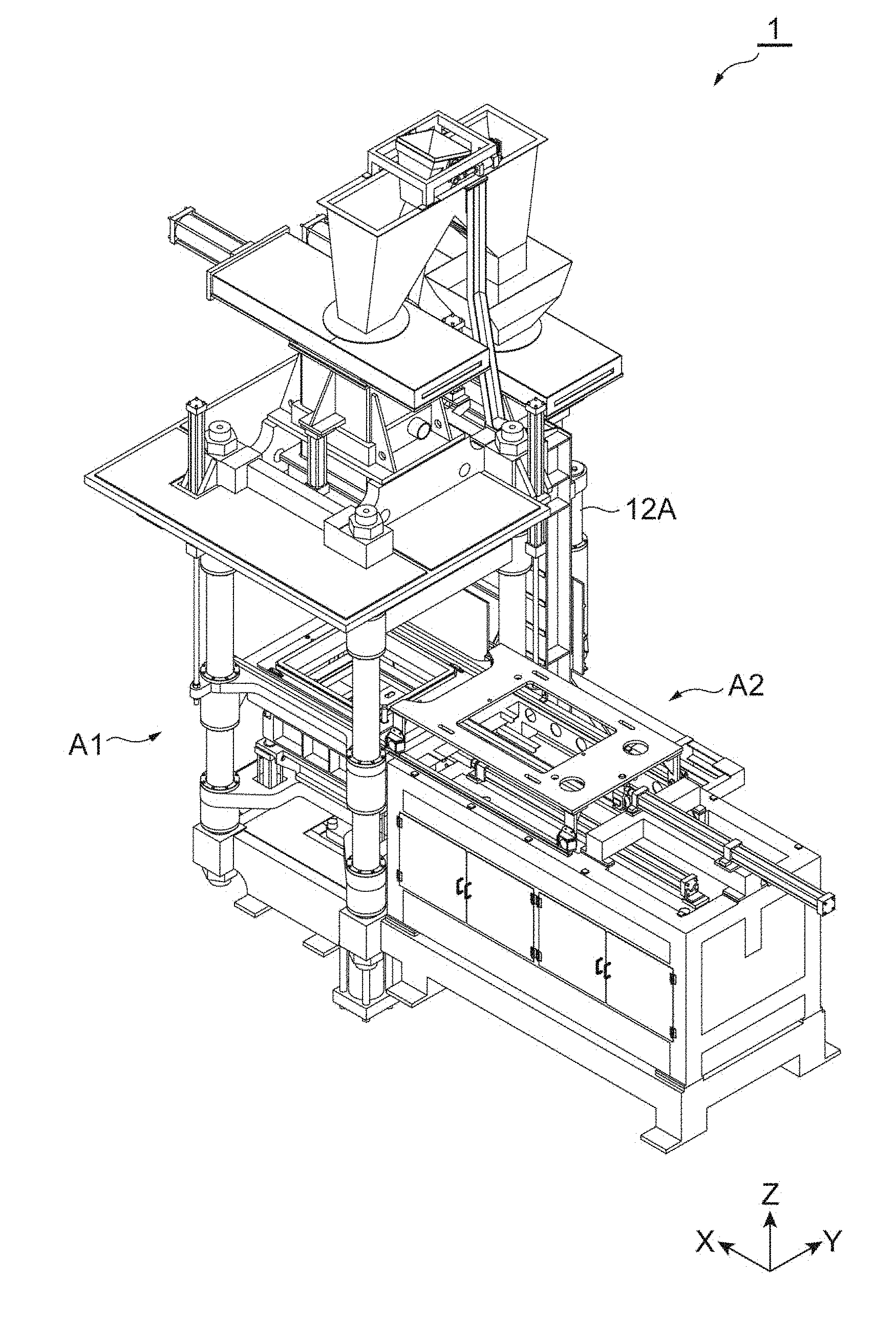
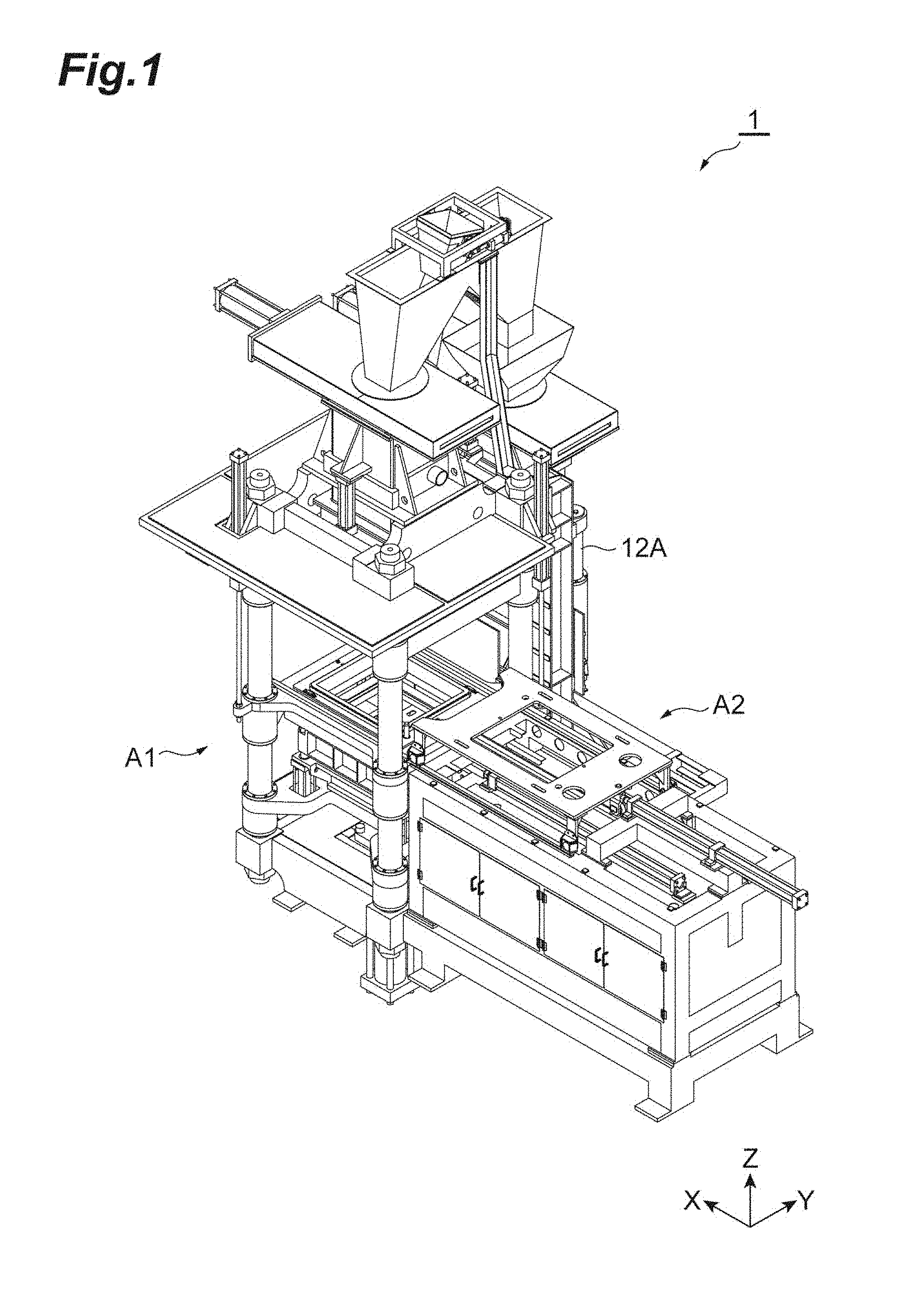
[0021] FIG. 1 is a perspective view on a front side of a flaskless molding machine according to one embodiment.
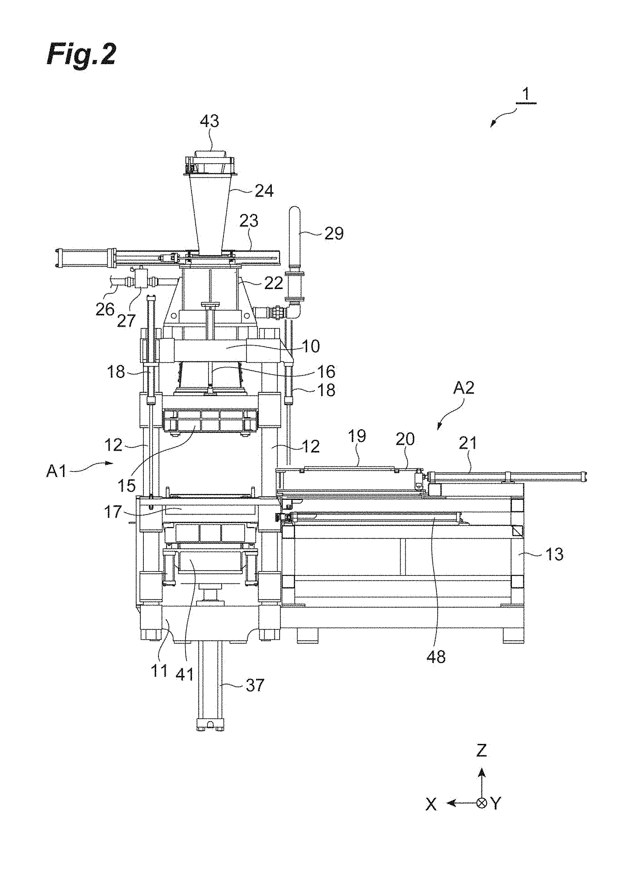
[0022] FIG. 2 is a front view of the flaskless molding machine according to one embodiment.
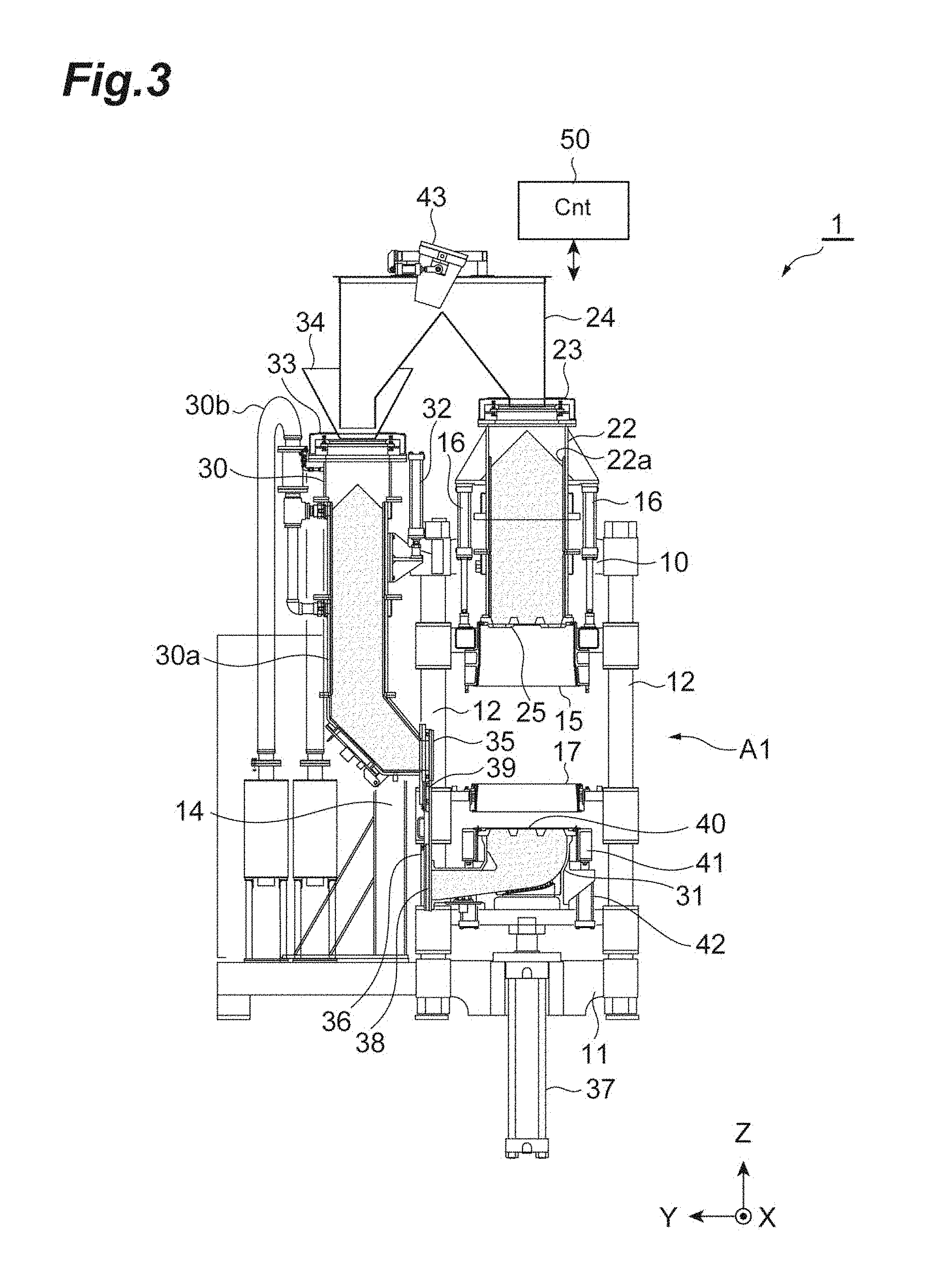
[0023] FIG. 3 is a schematic diagram on the left side of the flaskless molding machine according to one embodiment.
[0024] FIG. 4 is a partial sectional view in a state where a first lower sand tank and a second lower sand tank communicate with each other.
[0025] FIG. 5 is a plan view in the state where the first lower sand tank and the second lower sand tank communicate with each other.
[0026] FIG. 6 is a schematic diagram of a first communication port of the first lower sand tank.
[0027] FIG. 7 is a partially enlarged sectional view of a sealing mechanism.
[0028] FIG. 8 is a flowchart illustrating a molding process of the flaskless molding machine according to one embodiment.
[0029] FIG. 9 is a schematic diagram illustrating a shuttle-in process.
[0030] FIG. 10 is a schematic diagram illustrating a flask setting process.
[0031] FIG. 11 is a schematic diagram illustrating an aeration process.
[0032] FIG. 12 is a schematic diagram illustrating a squeeze process.
[0033] FIG. 13 is a schematic diagram illustrating a model-stripping process.
[0034] FIG. 14 is a schematic diagram illustrating a shuttle-out process.
[0035] FIG. 15 is a schematic diagram illustrating a flask alignment process.
[0036] FIG. 16 is a schematic diagram illustrating the flask-stripping process.
[0037] FIG. 17 is a schematic diagram illustrating a first flask separating process (first half).
[0038] FIG. 18 is a schematic diagram illustrating a mold extrusion process.
[0039] FIG. 19 is a schematic diagram illustrating a second flask separating process (latter half).
[0040] FIG. 20 shows an oil-hydraulic circuit of the flaskless molding machine according to one embodiment.
[0041] FIG. 21 is a schematic diagram illustrating a main part of a flaskless molding machine according to a modification example.
[0042] FIG. 22 shows the main part and the oil-hydraulic circuit of the flaskless molding machine according to the modification example.
DESCRIPTION OF EMBODIMENTS
[0043] Hereinafter, embodiments are described with reference to the drawings. The identical or corresponding portions in the diagrams are assigned identical signs, and redundant description is omitted. Hereinafter, the horizontal directions are assumed as X-axis and Y-axis directions, and the vertical direction (upward and downward direction) is assumed as a Z-axis direction.
[0044] [Overview of Flaskless Molding Machine]
[0045] FIG. 1 is a perspective view on a front side of a flaskless molding machine 1 according to one embodiment. The flaskless molding machine 1 is a molding machine that forms a flaskless upper mold and lower mold. As shown in FIG. 1, the flaskless molding machine 1 includes a molding unit A1, and a conveyance unit A2. In the molding unit A1, an upper flask and a lower flask that have box shapes and are movable in the vertical direction (Z-axis direction) are disposed. The conveyance unit A2 introduces a match plate where models are arranged, to the molding unit A1. The upper flask and the lower flask of the molding unit A1 are moved to be close to each other, and clamp the match plate. The inside of the upper flask and the inside of the lower flask are filled with mold sand. The mold sand filled in the upper flask and the lower flask are pressurized in the vertical direction by a squeeze mechanism included in the molding unit A1, and the upper mold and the lower mold are simultaneously formed. Subsequently, an upper mold and a lower mold are stripped from the upper flask and the lower flask, respectively, and are conveyed to the outside of the machine. As described above, the flaskless molding machine 1 forms the flaskless upper mold and lower mold.
[0046] [Frame Structure]
[0047] FIG. 2 is a front view of the flaskless molding machine 1 according to one embodiment. FIG. 3 is a schematic diagram on the left side of the flaskless molding machine 1 according to one embodiment. As shown in FIGS. 2 and 3, the flaskless molding machine 1 includes an upper frame 10, a lower frame 11, and four guides 12 that connect the upper frame 10 and the lower frame 11. As for the guides 12, their upper ends are connected to the upper frame 10, and their lower ends are connected to the lower frame 11. The frame of the molding unit A1 described above is made up of the upper frame 10, the lower frame 11 and the four guides 12.
[0048] On a side of the frame of the molding unit A1 (in the negative direction on the X-axis), a support frame 13 (FIG. 2) of the conveyance unit A2 is disposed. Furthermore, on a side of the frame of the molding unit A1 (the positive direction on the Y-axis), a support frame 14 (FIG. 3) extending in the vertical direction is disposed. The support frame 14 supports a first lower sand tank described later.
[0049] [Upper Flask and Lower Flask]
[0050] The flaskless molding machine 1 includes an upper flask 15. The upper flask 15 is a box-shaped frame where the upper end and the lower end are open. The upper flask 15 is movably attached to the four guides 12. The upper flask 15 is supported by an upper flask cylinder 16 attached to the upper frame 10, and vertically moves along the guides 12 according to the operation of the upper flask cylinder 16.
[0051] The flaskless molding machine 1 includes a lower flask 17 disposed below the upper flask 15. The lower flask 17 is a box-shaped frame where the upper end and the lower end are open. The lower flask 17 is movably attached to the four guides 12. The lower flask 17 is supported by two lower flask cylinders 18 (FIG. 2) attached to the upper frame 10, and vertically moves along the guides 12 according to the operation of the lower flask cylinders 18. Hereinafter, a region encircled by the guides 12 is also called a formation position.
[0052] A match plate 19 (FIG. 2) is introduced between the upper flask 15 and the lower flask 17, from the conveyance unit A2. The match plate 19 is a plate-shaped member with models being disposed on both the surfaces thereof, and moves to and from between the upper flask 15 and the lower flask 17. According to a specific example, the support frame 13 of the conveyance unit A2 includes rails toward a formation position, a conveyance plate 20 having rollers disposed on the rails, and a conveyance cylinder 21 that operates the conveyance plate 20. The match plate 19 is disposed on the conveyance plate 20, and is disposed at the formation position between the upper flask 15 and the lower flask 17 by the operation of the conveyance cylinder 21. The upper flask 15 and the lower flask 17 can clamp the disposed match plate 19, in the vertical direction. Hereinafter, a region on the support frame 13 is also called a retracted position.
[0053] [Sand Tank]
[0054] The flaskless molding machine 1 includes an upper sand tank 22 disposed above the upper flask 15. The upper sand tank 22 is attached to the upper frame 10. More specifically, the upper sand tank 22 is statically fixed to the upper frame 10. The upper sand tank 22 internally stores mold sand to be supplied to the upper flask 15. The upper sand tank 22 is open at its upper end and lower end. The upper end of the upper sand tank 22 is provided with a slide gate 23 that slides a plate-shaped shield member in the horizontal direction (the positive and negative directions on the X-axis). The upper sand tank 22 is configured so that its upper end can be opened and closed by the operation of the slide gate 23. A mold sand loading chute 24 that loads mold sand is fixedly disposed above the upper sand tank 22. The mold sand loading chute 24 is described later. When the slide gate 23 is in an open state, the mold sand is supplied through the mold sand loading chute 24 to the upper sand tank 22.
[0055] The lower end of the upper sand tank 22 is open, and an upper plate 25 (FIG. 3) is attached to the opening at the lower end. The upper plate 25 is a plate-shaped member, and has at least one supply port through which the upper sand tank 22 and the inside of the upper flask 15 communicate with each other. The mold sand in the upper sand tank 22 is supplied through the supply port of the upper plate 25 into the upper flask 15. The upper plate 25 has a size substantially identical to the size of the opening of the upper flask 15. The upper flask 15 moves in the upward direction, thereby causing the upper plate 25 to enter the inside of the upper flask 15. The upper flask 15 moves in the downward direction, thereby retracting the upper plate 25 from the upper flask 15. As described above, the upper plate 25 is configured to be capable of entering and being retracted from the inside of the upper flask 15. The details of the upper plate 25 are described later.
[0056] The upper sand tank 22 communicates with a compressed air source (not shown). According to a specific example, the upper sand tank 22 communicates, at its upper portion, with a pipe 26 (FIG. 2) for supplying compressed air, and communicates with the compressed air source through the pipe 26. The pipe 26 is provided with an electro-pneumatic proportional valve 27 (FIG. 2). The electro-pneumatic proportional valve 27 not only switches supply and stop of compressed air but also automatically adjusts the valve opening degree according to the pressure on the output side. Accordingly, the compressed air at a predetermined pressure is supplied to the upper sand tank 22. When the slide gate 23 is in a closed state, the compressed air supplied from the upper portion of the upper sand tank 22 is blown toward the lower portion of the upper sand tank 22. The mold sand in the upper sand tank 22 is supplied, together with the compressed air, through the supply port of the upper plate 25 into the upper flask 15.
[0057] The upper sand tank 22 is provided, on its inner surface, with a permeation member 22a (FIG. 3) having a plurality of pores that allow the compressed air to pass. Accordingly, the compressed air is supplied through the entire surface of the permeation member 22a to the entire inner space, thereby improving the fluidity of the mold sand. The permeation member 22a may be formed of a porous material. The upper sand tank 22 communicates, at its side portion, with a pipe (not shown) for supplying compressed air, and a pipe 29 (FIG. 2) for discharging the compressed air. The pipe 29 is provided with a filter that does not allow the mold sand to pass but allows the compressed air to pass, and can prevent the mold sand from being discharged to the outside of the upper sand tank 22.
[0058] The flaskless molding machine 1 includes a lower sand tank that stores mold sand to be supplied into the lower flask 17. According to an example, the lower sand tank is divided into a first lower sand tank 30 (FIG. 3) and a second lower sand tank 31 (FIG. 3). The first lower sand tank 30 is disposed on a side of the upper sand tank 22. The first lower sand tank 30 internally stores mold sand to be supplied to the lower flask 17.
[0059] The first lower sand tank 30 is supported by the support frame 14, and is movably attached to a vertically extending guide 12A (FIG. 1) provided for the support frame 14. More specifically, the first lower sand tank 30 is supported by a lower tank cylinder (adjustment drive unit) 32 (FIG. 3) attached to the upper frame 10, and vertically moves along the guide 12A according to the operation of the lower tank cylinder 32.
[0060] The first lower sand tank 30 is open at its upper end. The upper end of the first lower sand tank 30 is provided with a slide gate 33 (FIG. 3) that slides a plate-shaped shield member in the horizontal direction (the positive and negative directions on the X-axis). The first lower sand tank 30 is configured so that its upper end can be opened and closed by the operation of the slide gate 33. A hopper 34 (FIG. 3) for loading mold sand is fixedly disposed above the first lower sand tank 30. The communication relationship between the hopper 34 and the mold sand loading chute 24 is described later. When the slide gate 33 is in an open state, the mold sand is supplied through the hopper 34 to the first lower sand tank 30.
[0061] The first lower sand tank 30 is bent at its lower end in the horizontal direction (the negative direction on the Y-axis), and, at its distal end, a first communication port 35 (FIG. 3) for discharging the stored mold sand is formed. The first communication port 35 is configured so that this port can communicate with an after-mentioned second communication port of the second lower sand tank 31 at a predetermined height (communication position). The mold sand is supplied through the first communication port 35 to the second lower sand tank 31. The distal end of the first lower sand tank 30 is provided with a first block plate 36 (FIG. 3) that extends in the vertical direction. When an after-mentioned second communication port of the second lower sand tank 31 is not at a communication position, this port is shielded by the first block plate 36.
[0062] The first lower sand tank 30 communicates with the compressed air source (not shown). According to a specific example, the first lower sand tank 30 communicates, at its upper portion, with a pipe (not shown) for supplying compressed air, and communicates with the compressed air source through the pipe. The pipe is provided with an electro-pneumatic proportional valve (not shown). Accordingly, the compressed air at a predetermined pressure is supplied to the first lower sand tank 30. When the slide gate 33 is in the closed state and the after-mentioned second communication port of the second lower sand tank 31 is at the communication position, the compressed air is supplied through the upper portion of the first lower sand tank 30. The compressed air is blown toward the lower portion of the first lower sand tank 30, and the mold sand in the first lower sand tank 30 is supplied together with the compressed air through the first communication port 35 into the second lower sand tank 31.
[0063] The first lower sand tank 30 is provided, on its inner surface, with a permeation member 30a (FIG. 3) having a plurality of pores that allow the compressed air to pass. Accordingly, the compressed air is supplied through the entire surface of the permeation member 30a to the entire inner space, thereby improving the fluidity of the mold sand. The permeation member 30a may be formed of a porous material. A side portion of the first lower sand tank 30 communicates with a pipe 30b (FIG. 3) for discharging the compressed air. The pipe 30b is provided with a filter that does not allow the mold sand to pass but allows the compressed air to pass, and can prevent the mold sand from being discharged to the outside of the first lower sand tank 30.
[0064] The second lower sand tank 31 is disposed below the lower flask 17. The second lower sand tank 31 internally stores mold sand to be supplied to the lower flask 17. The second lower sand tank 31 is movably attached to the four guides 12, and is supported in a vertically movable manner by a vertically extending squeeze cylinder (lower flask drive unit) 37.
[0065] At a side portion of the second lower sand tank 31, a second communication port 38 (FIG. 3) that can communicate with the first communication port 35 of the first lower sand tank is formed. The second communication port 38 is configured so that this port can communicate with the first communication port 35 of the first lower sand tank 30 at a predetermined height (communication position). The communication position has a height at which the first communication port 35 and the second communication port 38 communicate with each other and, more specifically, is a position at which the first communication port 35 and the second communication port 38 are disposed concentrically with each other. The first communication port 35 and the second communication port 38 communicate with each other on a communication plane along the vertical direction.
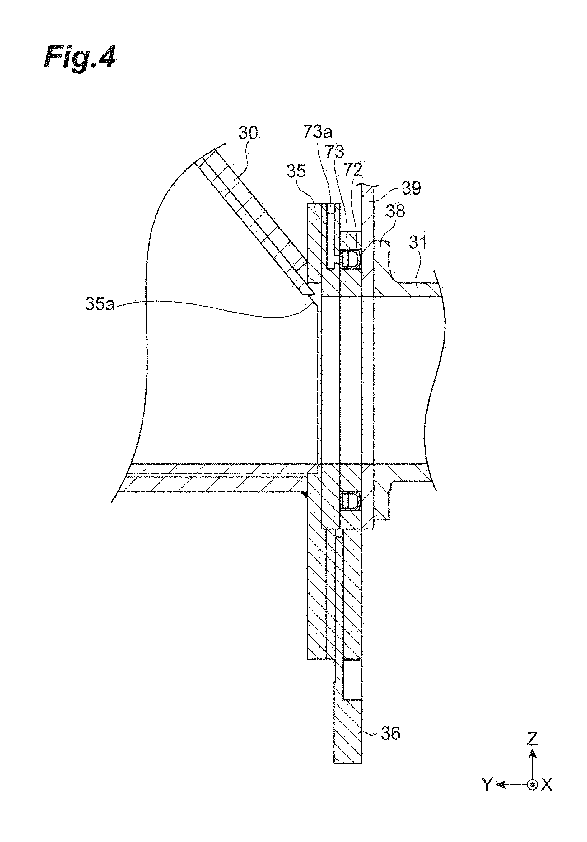
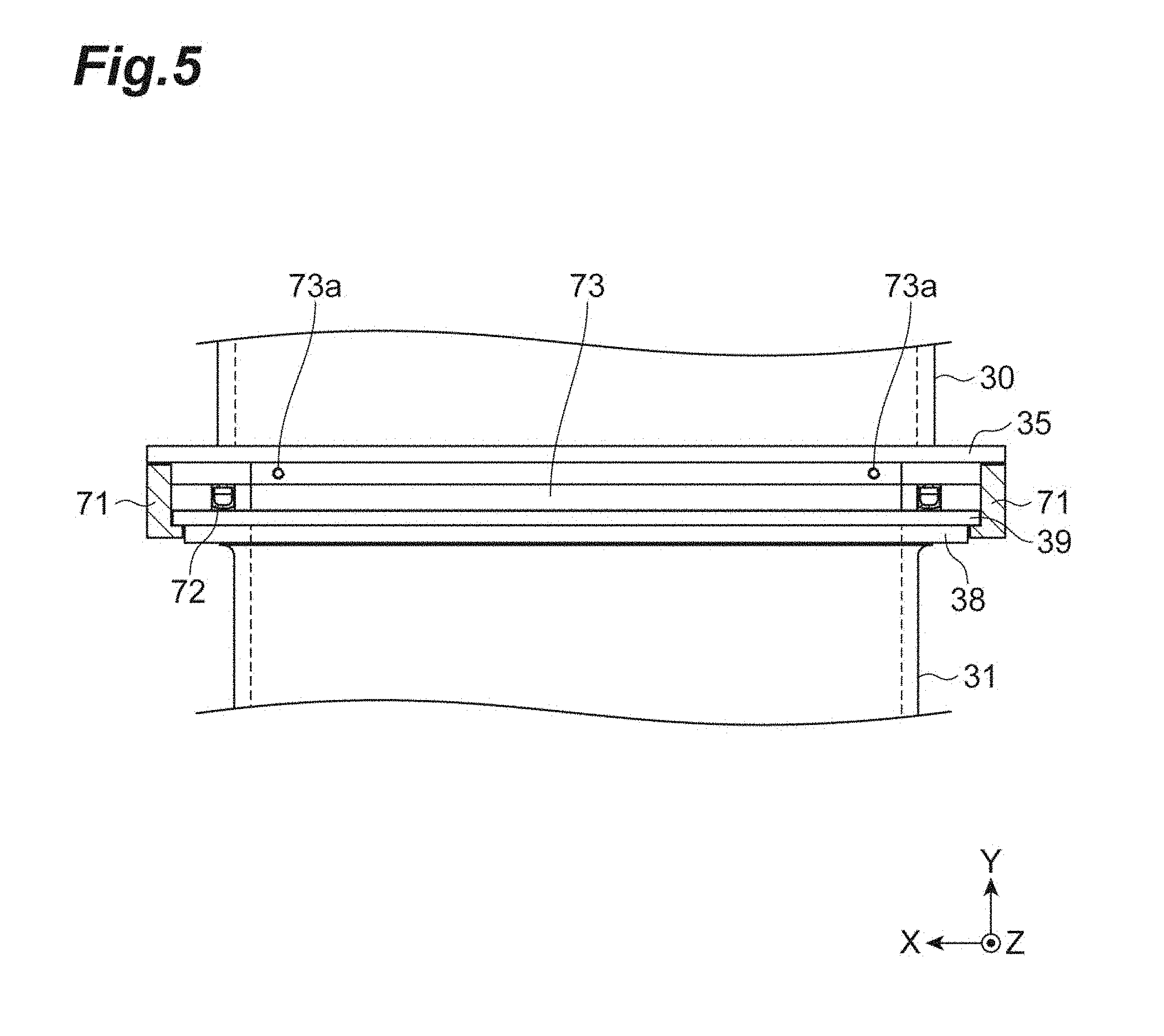
[0066] FIG. 4 is a partial sectional view in the state where the first lower sand tank 30 and the second lower sand tank 31 communicate with each other. FIG. 5 is a plan view in the state where the first lower sand tank 30 and the second lower sand tank 31 communicate with each other. As shown in FIGS. 4 and 5, the first lower sand tank 30 and the second lower sand tank 31 are in a state of communicating with each other through communication between the first communication port 35 and the second communication port 38 being at the predetermined communication position. The mold sand is supplied through the first communication port 35 and the second communication port 38 from the first lower sand tank 30 to the second lower sand tank 31. The second communication port 38 of the second lower sand tank 31 is provided with a vertically extending second block plate 39 (FIGS. 3 to 5). The opposite sides of the first communication port 35 of the first lower sand tank 30 are provided with guide rails 71 (FIG. 5) that guide a second block plate 39. The second block plate 39 is guided by the guide rails 71, thereby allowing the first communication port 35 and the second communication port 38 to be guided to the communication position without being inclined from each other. When the first communication port 35 of the first lower sand tank 30 is not at the communication position, this port is shielded by the second block plate 39.
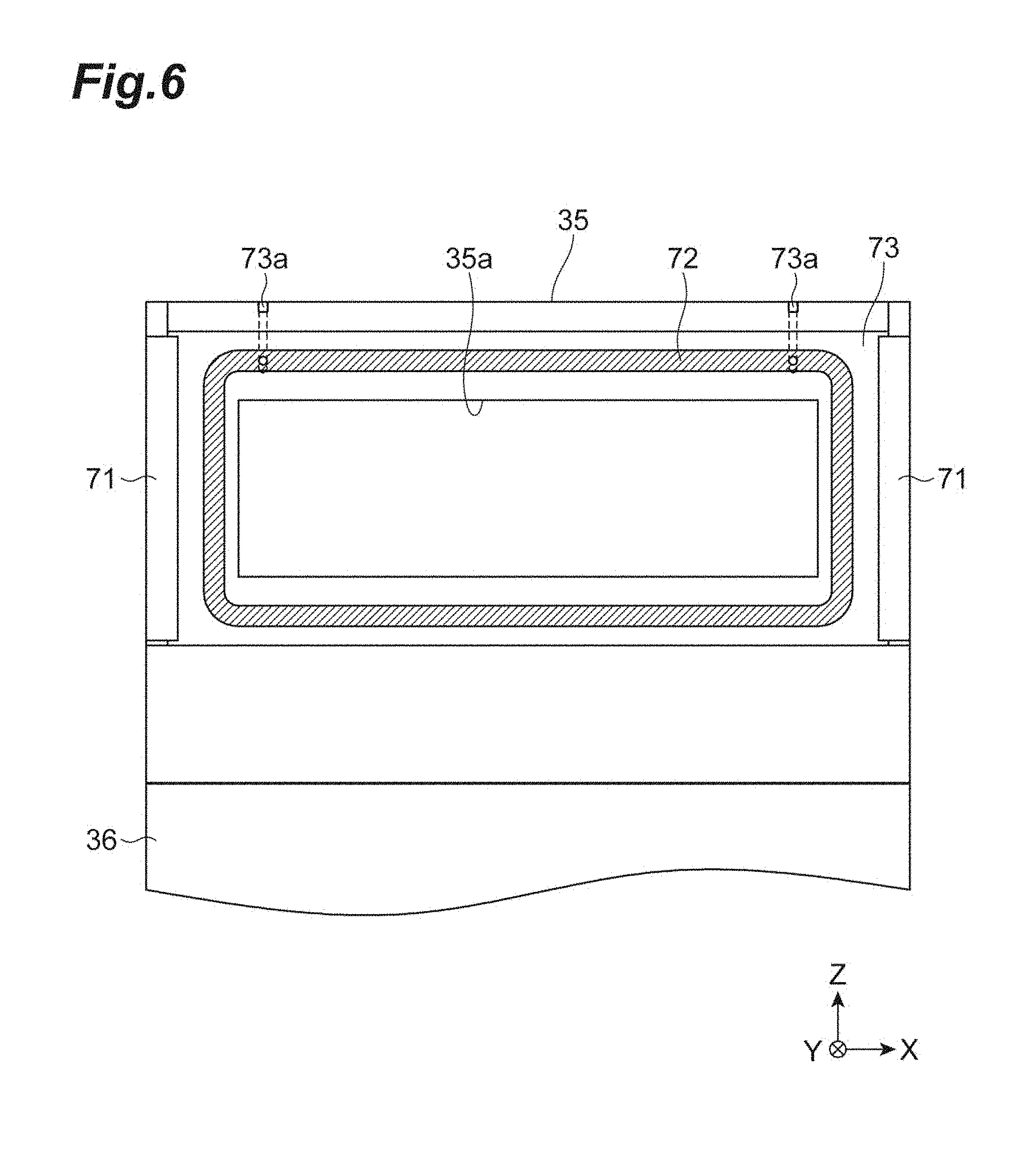
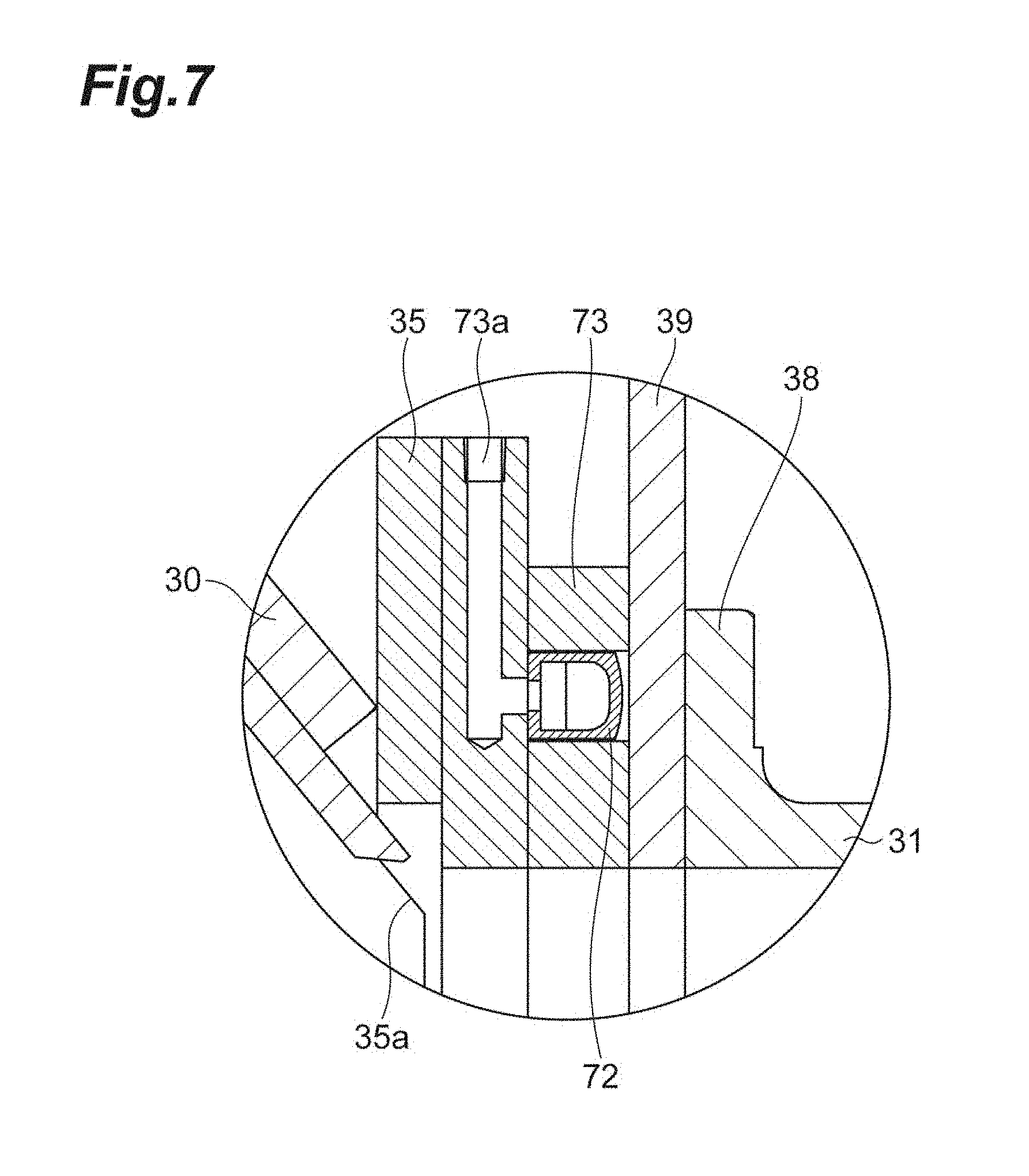
[0067] It should be noted that the flaskless molding machine 1 may include a sealing mechanism that hermetically seals the communication planes of the first communication port 35 and the second communication port 38. For example, the sealing mechanism is provided on the first communication port 35 side. FIG. 6 is a schematic diagram of the first communication port 35 of the first lower sand tank 30, and is a diagram showing the first communication port 35 from the open side. As shown in FIG. 6, the first communication port 35 has an opening 35a that communicates with the inside of the first lower sand tank 30. The sealing mechanism includes a sealing member 72 and a holding member 73. The sealing member 72 is an annular member that encircles the opening 35a. The sealing member 72 has a tubular shape that can guide gas into its inside, and has a flexibility. The holding member 73 is an annular member that encircles the opening 35a, and is in contact with the second block plate 39. A groove that can accommodate the sealing member 72 is formed on a surface of the holding member 73 with which the second block plate 39 is in contact. FIG. 7 is a partially enlarged sectional view of the sealing mechanism. As shown in FIG. 7, the sealing member 72 is accommodated to an extent not extruding from the surface of the holding member 73 with which the second block plate 39 is in contact. At the holding member 73, a gas guide port 73a (FIGS. 4 to 7) that communicates with the sealing member 72 is formed. The sealing member 72 is inflated when gas is introduced into its inside, and extrudes from the surface of the holding member 73 to enclose hermetically the communication planes of the first communication port 35 and the second communication port 38. It should be noted that the flaskless molding machine 1 may adopt a sealing mechanism other than the sealing mechanism shown in FIGS. 4 to 7.
[0068] The upper end of the second lower sand tank 31 is open, and a lower plate 40 (FIG. 3) is attached to the opening at the upper end. The lower plate 40 is a plate-shaped member, and has at least one supply port through which the second lower sand tank 31 and the inside of the lower flask 17 communicate with each other. The mold sand in the second lower sand tank 31 is supplied through the supply port of the lower plate 40 and an after-mentioned lower filling frame into the lower flask 17. The details of the lower plate 40 are described later.
[0069] [Lower Filling Frame]
[0070] The flaskless molding machine 1 includes, for example, a lower filling frame 41 (FIGS. 2, 3). The lower filling frame 41 is disposed below the lower flask 17. The lower filling frame 41 is a box-shaped frame where the upper end and the lower end are open. The opening at the upper end of the lower filling frame 41 (upper opening) communicates with the opening at the lower end of the lower flask 17 (lower opening). The lower filling frame 41 is configured so that its inside can accommodate the second lower sand tank 31. The lower filling frame 41 is supported in a vertically movable manner by a lower filling frame cylinder 42 (FIG. 3) fixed to the second lower sand tank 31. The lower plate 40 has a size substantially identical to each of the sizes of openings of the lower filling frame 41 and the lower flask 17. A position where the vertically movable lower filling frame 41 internally accommodates the second lower sand tank 31 and the lower plate 40 is an original position (initial position), and serves as a descending end. The lower filling frame 41 moves in the upward direction, thereby retracting the lower plate 40 from the lower filling frame 41. The lower filling frame 41 having moved in the upward direction is moved in the downward direction, thereby allowing the lower plate 40 to enter the inside of the lower filling frame 41. As described above, the lower plate 40 is configured to be capable of entering and being retracted from the inside of the lower filling frame 41 (movable to and from). The flaskless molding machine 1 can reduce the stroke of the lower flask 17 by including the lower filling frame 41. Consequently, the flaskless molding machine having a lower machine height can be achieved in comparison with a case of not including the lower filling frame 41. Furthermore, as the flaskless molding machine 1 can reduce the stroke of the lower flask 17 by including the lower filling frame 41, the molding time of the pair of the upper mold and the lower mold can be reduced.
[0071] It should be noted that the flaskless molding machine 1 does not necessarily include the lower filling frame 41. In this case, the lower plate 40 is configured to be capable of entering and being retracted from the inside of the lower flask 17 (movable to and from). The descending end of the vertically movable lower flask 17 is the original position (initial position). That is, the lower plate 40 enters the inside of the lower flask 17 by moving in the upward direction relatively more than the lower flask 17 moving in the upward direction. The lower plate 40 is retracted from the lower flask 17 by moving in the downward direction relatively more than the lower flask 17.
[0072] [Molding Space and Squeeze]
[0073] The molding space (upper molding space) of the upper mold is formed by the upper plate 25, the upper flask 15 and the match plate 19. The molding space (lower molding space) of the lower mold is formed by the lower plate 40, the lower flask 17 and the match plate 19. The upper molding space and the lower molding space are formed when the upper flask cylinder 16, the lower flask cylinders 18 and the squeeze cylinder 37 are operated and the upper flask 15 and the lower flask 17 clamp the match plate at a predetermined height. In a case where the flaskless molding machine 1 includes the lower filling frame 41, the lower molding space may be formed by the lower plate 40, the lower flask 17, the lower filling frame 41 and the match plate 19.
[0074] The upper molding space is filled with the mold sand stored in the upper sand tank 22, through the upper plate 25. The lower molding space is filled with the mold sand stored in the second lower sand tank 31, through the lower plate 40. The CB of the mold sand with which the upper molding space and the lower molding space are filled may be set in a range from 30% to 42%. The compressive strength of the mold sand with which the upper molding space and the lower molding space are filled may be set in a range from 8 to 15 N/cm.sup.2. It should be noted that as the thickness of the mold to be formed is changed according to the model shape and the CB (compactability) of the mold sand, the height of a target of the second lower sand tank 31 is changed according to the thickness of the mold. That is, the height of the second communication port 38 of the second lower sand tank 31 is changed. At this time, the height of the first communication port 35 of the first lower sand tank 30 is adjusted to be at the communication position of the second communication port 38 of the second lower sand tank 31 by the lower tank cylinder 32. Such adjustment can be achieved by an after-mentioned control device 50 (FIG. 3).
[0075] In a state where the upper molding space and the lower molding space are filled with the mold sand, the squeeze cylinder 37 performs squeezing with the upper plate 25 and the lower plate 40 by moving the second lower sand tank 31 upward. Accordingly, a pressure is applied to the mold sand in the upper molding space, and the upper mold is formed. At the same time, a pressure is applied to the mold sand in the lower molding space, and the lower mold is formed.
[0076] [Mold Sand Loading Chute]
[0077] The mold sand loading chute 24 is open at the upper end, and is bifurcated at the lower end. The upper end is provided with a switch damper 43. The switch damper 43 changes its inclination direction so that the mold sand can fall to any one of the bifurcated lower end portions. One lower end portion of the mold sand loading chute 24 is fixed to the upper portion of the upper sand tank 22, and the other lower end portion of the mold sand loading chute 24 is accommodated in the hopper 34 and is not fixed. Since the lower end portion on the first lower sand tank 30 side is not fixed as described above, the lower tank cylinder 32 can control the height of the first communication port 35 of the first lower sand tank 30 independently from the upper sand tank 22.
[0078] [Control Device]
[0079] The flaskless molding machine 1 may include a control device 50. The control device 50 is a computer that includes a control unit such as a processor, a storage unit such as a memory, an input and output unit such as an input device and a display device, and a communication unit such as a network card, and controls each of units of the flaskless molding machine 1, for example, a mold sand supply system, a compressed air supply system, a drive system, a power source system and the like. The control device 50 allows an operator to perform a command input operation and the like in order to manage the flaskless molding machine 1, using the input device, and can cause the display device to visualize and display the operation situations of the flaskless molding machine 1. Furthermore, the storage unit of the control device 50 stores a control program for allowing the processor to control various processes to be executed by the flaskless molding machine 1, and a program for causing each configuration unit of the flaskless molding machine 1 to execute processes according to a molding condition.
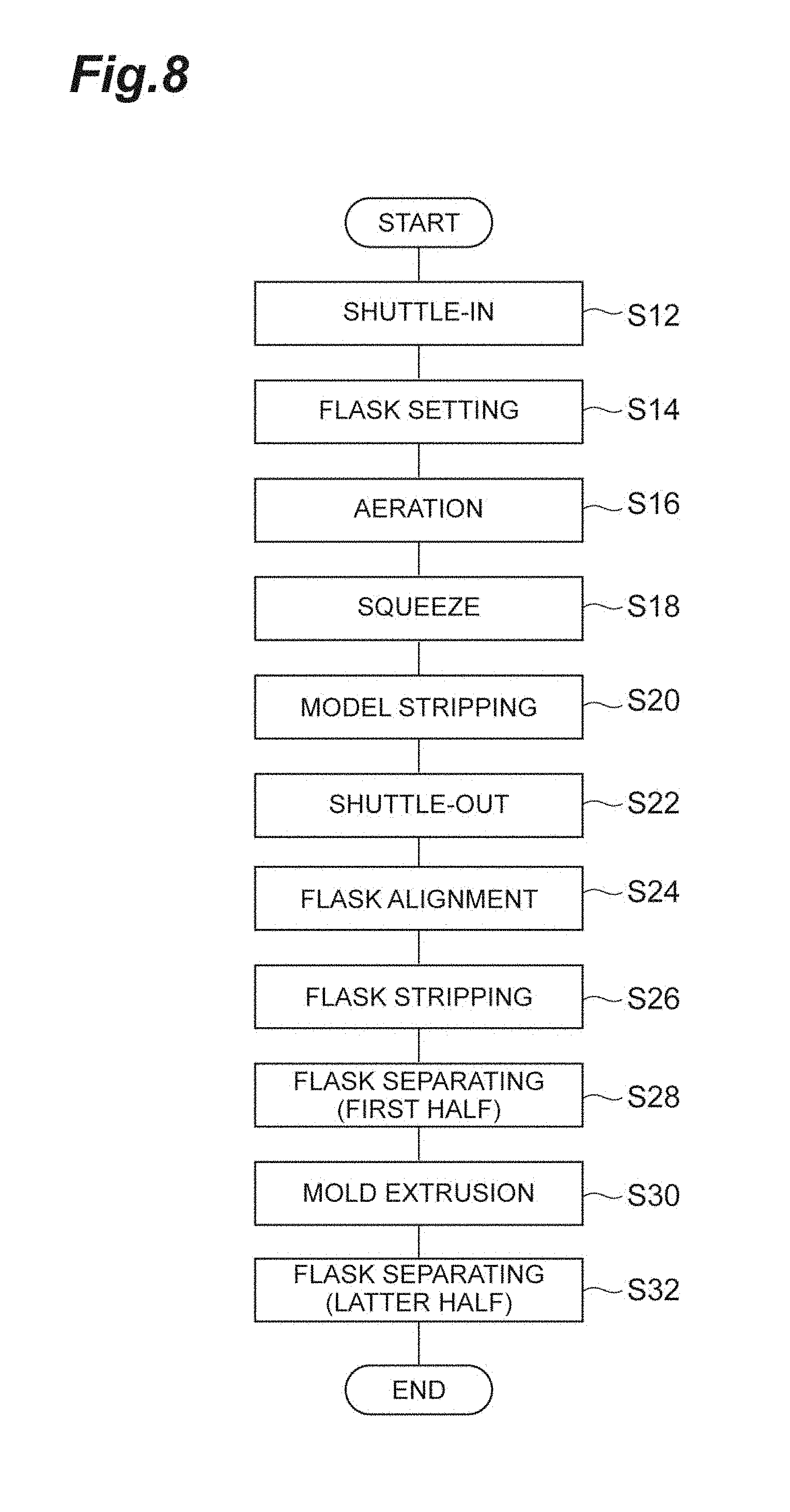
[0080] [Molding Process]
[0081] An overview of a molding process according to this embodiment is described. FIG. 8 is a flowchart illustrating the molding process of the flaskless molding machine according to one embodiment. The molding process shown in FIG. 8 is a process of molding a pair of the upper mold and the lower mold. The molding process shown in FIG. 8 is automatically activated with a condition that the attitude of the flaskless molding machine 1 is the original position (initial position). When the attitude of the flaskless molding machine 1 is not at the original position, this machine is manually operated to be moved to the original position. When an automatic activation button is pressed with the attitude (original position) of the flaskless molding machine 1 shown in FIG. 3, the molding process shown in FIG. 8 is started.
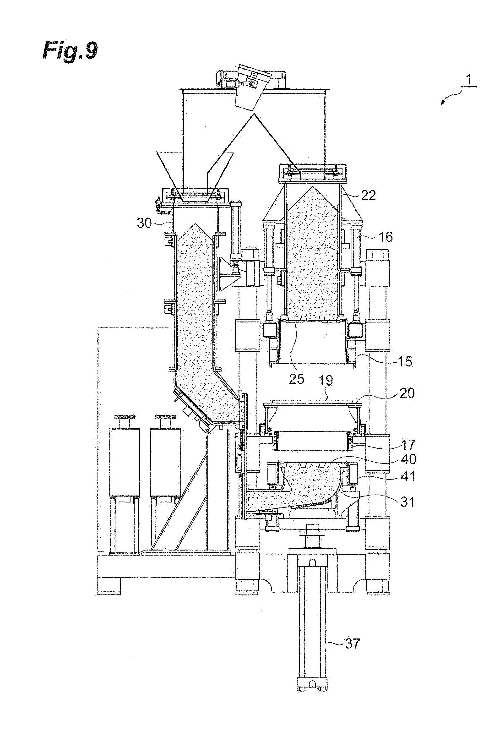
[0082] When the molding process is started, a shuttle-in process (S12) is performed first. FIG. 9 is a schematic diagram illustrating the shuttle-in process. As shown in FIG. 9, in the shuttle-in process, the conveyance cylinder 21 moves the conveyance plate 20 mounted with the match plate 19 to a molding position.
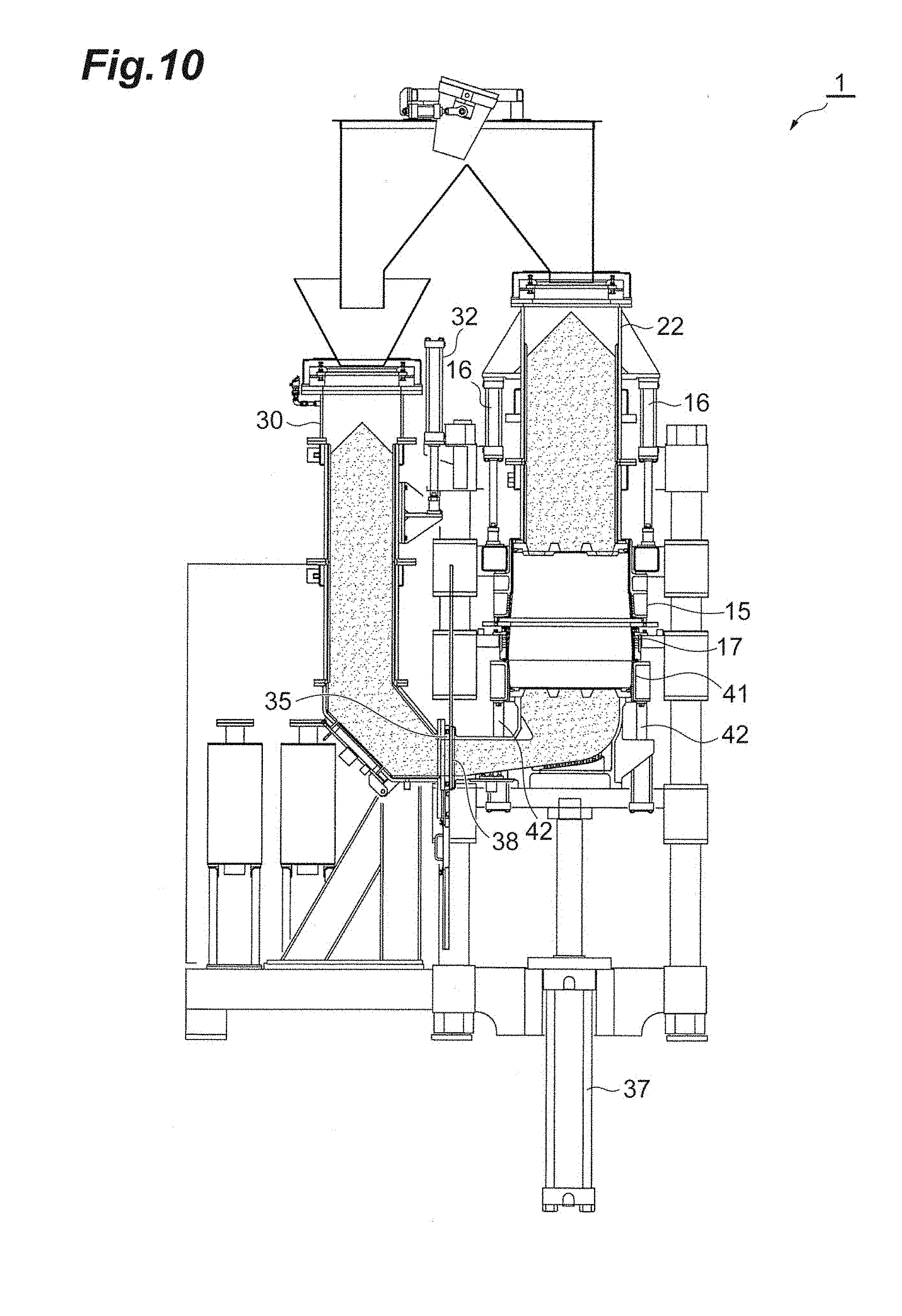
[0083] Next, a flask setting process (S14) is performed. FIG. 10 is a schematic diagram illustrating the flask setting process. As shown in FIG. 10, in the flask setting process, the upper flask cylinder 16, the lower flask cylinders 18 (FIG. 2), the lower filling frame cylinder 42 and the squeeze cylinder 37 are elongated and contracted in conformity with the thicknesses of the molds to be formed. Accordingly, the upper flask 15 is moved to the predetermined position, and the lower flask 17 comes into contact with the match plate 19, and subsequently, the lower flask 17 mounted with the match plate 19 is moved to the predetermined position, thereby achieving a state where the match plate 19 is clamped between the upper flask 15 and the lower flask 17. The second lower sand tank 31 and the lower filling frame 41 then rise, and the lower filling frame 41 comes into contact with the lower flask 17. The lower tank cylinder 32 is elongated and contracted to move the first lower sand tank 30 in the vertical direction, thereby achieving a state where the height of the first communication port 35 of the first lower sand tank 30 coincides with the height of the second communication port 38 of the second lower sand tank 31. At this time, the upper molding space and the lower molding space are in a state (height) determined by the control device 50.
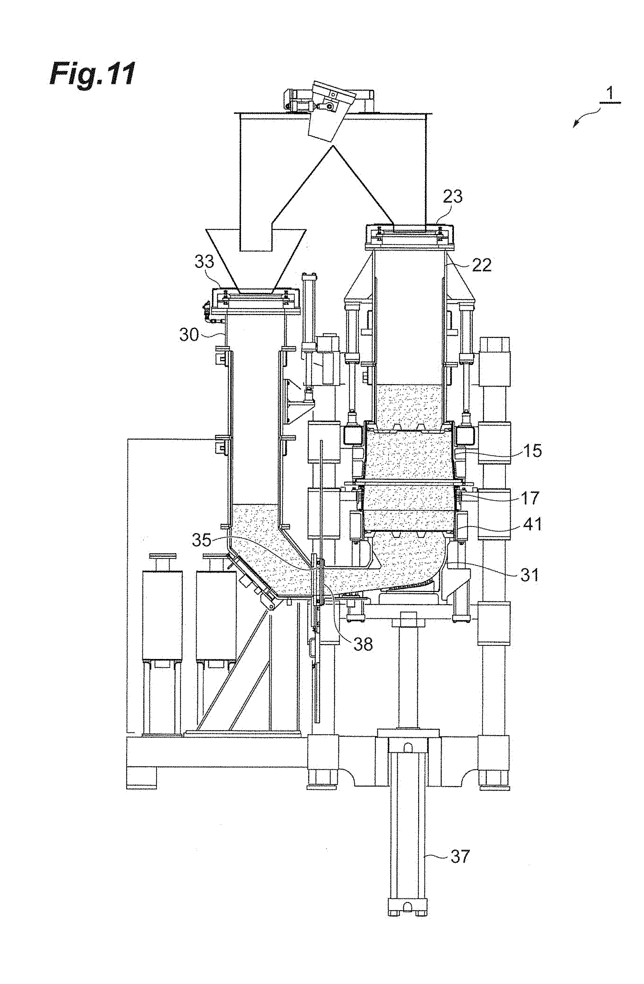
[0084] Next, an aeration process (S16) is performed. FIG. 11 is a schematic diagram illustrating the aeration process. As shown in FIG. 11, in the aeration process, the sealing mechanism seals the first communication port 35 of the first lower sand tank 30 and the second communication port 38 of the second lower sand tank 31. The slide gate 23 of the upper sand tank 22 and the slide gate 33 of the first lower sand tank 30 are then closed, and the compressed air source and the electro-pneumatic proportional valve supply compressed air to the upper sand tank 22 and the first lower sand tank 30. Accordingly, the upper molding space and the lower molding space are filled with the mold sand while the mold sand is allowed to flow. For example, if the set pressure and time are satisfied, the aeration process is finished.
[0085] Next, a squeeze process (S18) is performed. FIG. 12 is a schematic diagram illustrating the squeeze process. As shown in FIG. 12, in the squeeze process, the sealing mechanism having been operated in the aeration process (S16) releases the sealing, and the squeeze cylinder 37 is further elongated, thereby further raising the second lower sand tank 31. Accordingly, the lower plate 40 attached to the second lower sand tank 31 enters the inside of the lower filling frame 41 and compresses the mold sand in the lower molding space, while the upper plate 25 enters the inside of the upper flask 15 and compresses the mold sand in the upper molding space. In a case where the squeeze cylinder 37 is controlled by an oil-hydraulic circuit, the squeeze process is finished when the oil pressure of the oil-hydraulic circuit can be determined to be the same as the set oil pressure, for example. It should be noted that in a case where during the squeeze process, the upper flask cylinder 16, the lower flask cylinders 18 and the lower filling frame cylinder 42 are controlled by the oil-hydraulic circuit, each cylinder is set as a free circuit. Accordingly, each cylinder yields to the squeeze force and is contracted.
[0086] Next, a model-stripping process (S20) is performed. FIG. 13 is a schematic diagram illustrating the model-stripping process. As shown in FIG. 13, in the model-stripping process, the lower filling frame cylinder 42 is contracted to lower the lower filling frame 41. Subsequently, the squeeze cylinder 37 is contracted and lowers the second lower sand tank 31, and subsequently lowers the lower flask 17 mounted with the match plate 19 and the conveyance plate 20. The model is then stripped from the upper flask 15. When the lower flask 17 is lowered to a fixed unit (not shown), the match plate 19 and the conveyance plate 20 are supported by the fixed unit. Accordingly, the model is stripped from the lower flask 17.
[0087] Next, a shuttle-out process (S22) is performed. FIG. 14 is a schematic diagram illustrating the shuttle-out process. As shown in FIG. 14, in the shuttle-out process, the conveyance cylinder 21 is contracted, thereby moving the conveyance plate 20 to the retracted position. In the state shown in FIG. 14, a core is disposed in the upper flask 15 or the lower flask 17 if necessary.
[0088] Next, a flask alignment process (S24) is performed. FIG. 15 is a schematic diagram illustrating the flask alignment process. As shown in FIG. 15, in the flask alignment process, the lower flask cylinders 18 are contracted to elongate the squeeze cylinder 37, thereby raising the lower flask 17 and the second lower sand tank 31 to align the flask.
[0089] Next, the flask-stripping process (S26) is performed. FIG. 16 is a schematic diagram illustrating the flask-stripping process. As shown in FIG. 16, in the flask-stripping process, the upper flask cylinder 16 and the lower flask cylinders 18 are contracted, thereby raising the upper flask 15 and the lower flask 17 to the raised ends to strip the flask.
[0090] Next, a first flask separating process (S28) is performed. FIG. 17 is a schematic diagram illustrating the first flask separating process (first half). As shown in FIG. 17, in the first flask separating process, in a state where the mold is mounted on the lower plate 40 of the second lower sand tank 31, the squeeze cylinder 37 is contracted to lower the second lower sand tank 31. At this time, the lower flask cylinders 18 are elongated to lower the lower flask 17, and the mold is stopped at a position of not interfering with conveyance of the mold.
[0091] Next, a mold extrusion process (S30) is performed. FIG. 18 is a schematic diagram illustrating the mold extrusion process. As shown in FIG. 18, in the mold extrusion process, an extrusion cylinder 48 (see FIG. 2) is elongated, thereby conveying the upper mold and the lower mold to the outside of the machine (e.g., a molding line).
[0092] Next, a second flask separating process (S32) is performed. FIG. 19 is a schematic diagram illustrating the second flask separating process (latter half). As shown in FIG. 19, in the second flask separating process, the lower flask cylinders 18 are elongated to return the lower flask 17 to the original position.
[0093] As described above, the process of forming the pair of the upper mold and the lower mold is thus finished.
[0094] [Oil-Hydraulic Circuit]
[0095] The squeeze cylinder 37, the upper flask cylinder 16 and the lower filling frame cylinder 42 may be made up of oil-hydraulic cylinders. FIG. 20 shows an oil-hydraulic circuit 60 of the flaskless molding machine 1 according to one embodiment. The oil-hydraulic circuit 60 is a circuit that communicates with an oil-hydraulic pump 61 and an oil tank 62, and drives the squeeze cylinder 37, the upper flask cylinder (upper flask oil-hydraulic cylinder) 16 and the lower filling frame cylinder (lower filling frame oil-hydraulic cylinder) 42, which are oil-hydraulic actuators. The oil-hydraulic circuit 60 includes a squeeze electromagnetic valve 63, an upper flask electromagnetic valve 64, an upper flask free electromagnetic valve 65 and an upper flask counterbalance valve 66, a lower filling frame electromagnetic valve 68, and a lower filling frame free electromagnetic valve 69 and a lower filling frame counterbalance valve 70. It should be noted that the oil-hydraulic circuit 60 is not limited to the mode described above. For example, an oil-hydraulic circuit, an oil-hydraulic pump and an oil tank may be prepared for each of the squeeze cylinder 37, the upper flask cylinder 16 and the lower filling frame cylinder 42. In the following description, an oil-hydraulic circuit for operating the squeeze cylinder 37 in the vertical direction is called a squeeze oil-hydraulic circuit 80, an oil-hydraulic circuit for operating the upper flask cylinder 16 in the vertical direction is called an upper flask oil-hydraulic circuit (first oil-hydraulic circuit) 81, and an oil-hydraulic circuit for operating the lower filling frame cylinder 42 in the vertical direction is called a lower filling frame oil-hydraulic circuit (second oil-hydraulic circuit) 83.
[0096] The operation of the squeeze cylinder 37 is controlled by the squeeze oil-hydraulic circuit 80. The squeeze oil-hydraulic circuit 80 includes the squeeze electromagnetic valve 63. The squeeze electromagnetic valve 63 is a valve that controls the direction in which oil flows to the squeeze cylinder 37. The squeeze cylinder 37 has an inner space on a rod side (a side where the piston rod of the cylinder protrudes), and an inner space on a non-rod side (a side where the piston rod of the cylinder does not protrude), and both the spaces communicate with the squeeze electromagnetic valve 63. The squeeze electromagnetic valve 63 allows the oil to flow into the inner space on the rod side, thereby causing the squeeze cylinder 37 to apply a power in a pulling direction. The squeeze electromagnetic valve 63 allows the oil to flow into the inner space on the non-rod side, thereby causing the squeeze cylinder 37 to apply a power in a pushing direction. As described above, the squeeze cylinder 37 is driven by the oil pressure. The squeeze cylinder 37 and the squeeze oil-hydraulic circuit 80 function as a drive unit that moves the lower plate 40 in the upward direction and performs a squeeze process.
[0097] The operation of the upper flask cylinder 16 is controlled by the upper flask oil-hydraulic circuit 81. The upper flask oil-hydraulic circuit 81 includes a first back pressure circuit 82 that applies, to the upper flask cylinder 16, a first back pressure that serves as a resistance against the upward movement of the upper flask 15 toward the upper plate 25 during the squeeze process of the drive unit. The upward movement of the upper flask 15 toward the upper plate 25 is, for example, movement of the upper flask 15 in such a way to be relatively upward with respect to the upper plate 25. More specifically, the upper flask oil-hydraulic circuit 81 includes the upper flask electromagnetic valve 64, the upper flask free electromagnetic valve 65, and the upper flask counterbalance valve 66. The upper flask electromagnetic valve 64 is an electromagnetic valve that controls the direction in which the oil flows to the upper flask cylinder 16. The upper flask cylinder 16 has an inner space on the rod side and an inner space on the non-rod side. Both the spaces communicate with the upper flask electromagnetic valve 64. The upper flask electromagnetic valve 64 allows the oil to flow into the inner space on the rod side, thereby causing the upper flask cylinder 16 to apply a power in the pulling direction. The upper flask electromagnetic valve 64 allows the oil to flow into the inner space on the non-rod side, thereby causing the upper flask cylinder 16 to apply a power in the pushing direction. As described above, the upper flask cylinder 16 is driven by the oil pressure.
[0098] The upper flask free electromagnetic valve 65 is an electromagnetic valve that frees the oil flowing to the upper flask cylinder 16. The upper flask cylinder 16 can be switched by the upper flask free electromagnetic valve 65 between a state of applying a power to the upper flask 15 and a state of not applying the power. The upper flask free electromagnetic valve 65 is a pressure control valve that adjusts the pressure of oil freed by the upper flask counterbalance valve 66. When the upper flask cylinder 16 is caused by the upper flask counterbalance valve 66 to apply a power in the pulling direction, a resistance force (first back pressure) occurs. That is, the back pressure control of the first back pressure circuit 82 is achieved by the upper flask counterbalance valve 66. It should be noted that the upper flask counterbalance valve 66 may be an electromagnetic relief valve that can control the pressure proportionally to the input voltage. By adopting the electromagnetic relief valve, an operator can adjust the pressure through a liquid crystal panel 67 and the like.
[0099] The operation of the lower filling frame cylinder 42 is controlled by the lower filling frame oil-hydraulic circuit 83. The lower filling frame oil-hydraulic circuit 83 includes a second back pressure circuit 84 that applies, to the lower filling frame cylinder 42, a second back pressure that serves as a resistance against the downward movement of the lower filling frame 41 toward the lower plate 40 during the squeeze process of the drive unit. The downward movement of the lower filling frame 41 toward the lower plate 40 is, for example, movement of the lower filling frame 41 in such a way to be relatively downward with respect to the lower plate 40. More specifically, the lower filling frame oil-hydraulic circuit 83 includes the lower filling frame electromagnetic valve 68, the lower filling frame free electromagnetic valve 69, and the lower filling frame counterbalance valve 70. The lower filling frame electromagnetic valve 68 is an electromagnetic valve that controls the direction in which the oil flows to the lower filling frame cylinder 42. The lower filling frame cylinder 42 has an inner space on the rod side and an inner space on the non-rod side. Both the spaces communicate with the lower filling frame electromagnetic valve 68. The lower filling frame electromagnetic valve 68 allows the oil to flow into the inner space on the rod side, thereby causing the lower filling frame cylinder 42 to apply a power in the pulling direction. The lower filling frame electromagnetic valve 68 allows the oil to flow into the inner space on the non-rod side, thereby causing the lower filling frame cylinder 42 to apply a power in the pushing direction. As described above, the lower filling frame cylinder 42 is driven by the oil pressure.
[0100] The lower filling frame free electromagnetic valve 69 is an electromagnetic valve that frees the oil flowing to the lower filling frame cylinder 42. The lower filling frame cylinder 42 can be switched by the lower filling frame free electromagnetic valve 69 between a state of applying a power to the lower filling frame 41 and a state of not applying the power. The lower filling frame counterbalance valve 70 is a pressure control valve that adjusts the pressure of oil freed by the lower filling frame free electromagnetic valve 69. When the lower filling frame cylinder 42 is caused by the lower filling frame counterbalance valve 70 to apply a power in the pulling direction, a resistance force (second back pressure) occurs. That is, the back pressure control of the second back pressure circuit 84 is achieved by the lower filling frame counterbalance valve 70. It should be noted that the lower filling frame counterbalance valve 70 may be an electromagnetic relief valve that can control the pressure proportionally to the input voltage. By adopting the electromagnetic relief valve, the operator can adjust the pressure through a liquid crystal panel 74 and the like.
[0101] By including the configuration described above, the balance adjusting operation of the squeeze force can be performed. During the squeeze process, the squeeze cylinder 37 is caused by the squeeze oil-hydraulic circuit 80 to apply a force in the pushing direction. At this time, if there is a resistance, the squeeze force is reduced. Consequently, the upper flask cylinder 16 is freed by the upper flask free electromagnetic valve 65 of the upper flask oil-hydraulic circuit 81, and the lower filling frame cylinder 42 is freed by the lower filling frame free electromagnetic valve 69 of the lower filling frame oil-hydraulic circuit 83. The squeeze force then occurs in the vertical direction between the upper plate 25 and the lower plate 40.
[0102] Here, when the squeeze force to the upper mold is larger than the squeeze force to the lower mold, that is, when the force of the squeeze cylinder 37 in the pushing direction is larger, the first back pressure serving as the resistance against the upward movement of the upper flask 15 toward the upper plate 25 may be applied by the first back pressure circuit 82 of the upper flask oil-hydraulic circuit 81 to the upper flask cylinder 16. Likewise, when the squeeze force to the lower mold is larger than the squeeze force to the upper mold, that is, when the force of the squeeze cylinder 37 in the pushing direction is insufficient, the second back pressure serving as the resistance against the downward movement of the lower filling frame 41 toward the lower plate 40 may be applied by the second back pressure circuit 84 of the lower filling frame oil-hydraulic circuit 83 to the lower filling frame cylinder 42.
[0103] As described above, in the flaskless molding machine 1 according to this embodiment, the lower plate 40 is moved in the upward direction by the drive unit, and the squeeze process is performed. The flaskless molding machine 1 can then cause the first back pressure or the second back pressure at the upper flask cylinder 16 or the lower filling frame cylinder 42 using the first back pressure circuit 82 and the second back pressure circuit 84. Consequently, this machine can apply a uniform pressure to the mold sand, and resultantly form an excellent mold or casting product.
[0104] Furthermore, the flaskless molding machine 1 according to this embodiment can control the balance of the squeeze forces by the back pressure of the upper flask cylinder 16 or the lower filling frame cylinder 42 while making the force of the squeeze cylinder 37 in the pushing direction constant. As described above, the need of adjustment on the squeeze cylinder 37 side is negated, thereby allowing the control to be simplified. Furthermore, unlike the conventional flaskless molding machine that controls the oil pressure of the squeeze cylinder 37 to turn ON (100%) and OFF (0%) to achieve the target value, an intermediate value, such as 80% or 60%, can be set. Consequently, the need for the rising time of the oil pressure during switching from OFF to ON is negated. Therefore, the lower plate 40 can be quickly operated to reduce the squeeze step. Resultantly, the time per cycle of the molding process shown in FIG. 8 can be reduced. Furthermore, in comparison with the ON-OFF control, tracking to the target value can be improved.
[0105] It should be noted that the embodiment described above is an example of the flaskless molding machine according to the present invention. The flaskless molding machine according to the present invention is not limited to the flaskless molding machine 1 according to the embodiment, and may be what is achieved by modifying the flaskless molding machine 1 according to the embodiment or by application to another machine in a range without changing the gist described in each claim.
Modification Example 1
[0106] In the embodiment described above, the squeeze cylinder 37 raises the lower plate 40 to cause the squeeze force. However, the configuration is not limited thereto. For example, the flaskless molding machine that performs squeezing by applying the squeeze forces through both the upper plate 25 and the lower plate 40 may be adopted. FIG. 21 is a schematic diagram illustrating a main part of a flaskless molding machine 1A according to a modification example. The flaskless molding machine 1A shown in FIG. 21 is a molding machine that forms a flaskless upper mold and lower mold, and includes a main part different from that of the flaskless molding machine 1. The flaskless molding machine 1A includes a pair of an upper flask 15A and a lower flask 17A. The upper flask 15A has a first opening 15a and a second opening 15b. The lower flask 17A has a third opening 17a, and a fourth opening 17b that can clamp a match plate 19A with the second opening 15b of the upper flask 15A. The upper flask 15A and the lower flask 17A clamp the match plate 19A. The flaskless molding machine 1A includes a lower filling frame 41A that has a fifth opening 41a, and a sixth opening 41b that can communicate with the third opening 17a of the lower flask 17A.
[0107] An upper plate 25A is disposed so that this plate can enter and be retracted from the first opening 15a of the upper flask 15A by an upper squeeze cylinder 80A. A lower plate 40A is disposed so that this plate can enter and be retracted from the fifth opening 41a of the lower filling frame 41A by a lower squeeze cylinder 37A. A flask-stripping cylinder 16A adjusts the positional relationship between the upper flask 15A and the upper plate 25A by adjusting the position of the upper plate 25A. The upper plate 25A is moved by the upper squeeze cylinder 80A in a direction of approaching the match plate 19A. The lower plate 40A is moved by the lower squeeze cylinder 37A in a direction of approaching the match plate 19A. Accordingly, squeeze forces are applied to both the upper flask 15A and the lower flask 17A to perform squeezing.
[0108] It should be noted that as for the flaskless molding machine 1A, the mold sand filling method is not specifically limited. FIG. 22 shows the main part and the oil-hydraulic circuit of the flaskless molding machine 1A according to the modification example.
[0109] As shown in FIG. 22, the main part of the flaskless molding machine 1A is rotated centered on a turning unit 100 by 90.degree. from the vertical direction to have an attitude for performing mold sand filling. It should be noted that as shown in FIG. 22, the lower filling frame 41A may be fixed on the station side for mold sand filling.
[0110] The oil-hydraulic circuit of the flaskless molding machine 1A is described. The oil-hydraulic circuit 60A is a circuit that communicates with an oil-hydraulic pump 88 and an oil tank 89, and drives the lower squeeze cylinder 37A, the upper squeeze cylinder 80A and the flask-stripping cylinder 16A, which are oil-hydraulic actuators. The oil-hydraulic circuit 60A includes a squeeze electromagnetic valve 90, a lower flask counterbalance valve 91, a flask-stripping electromagnetic valve 92, a flask-stripping free electromagnetic valve 93, and a flask-stripping counterbalance valve 94. It should be noted that the oil-hydraulic circuit 60A is not limited to the mode described above. For example, an oil-hydraulic circuit, an oil-hydraulic pump and an oil tank may be prepared for each of the lower squeeze cylinder 37A, the upper squeeze cylinder 80A and the flask-stripping cylinder 16A. Hereinafter, an oil-hydraulic circuit for operating the lower squeeze cylinder 37A and the upper squeeze cylinder 80A in the horizontal direction is called a squeeze oil-hydraulic circuit 96, and an oil-hydraulic circuit for operating the flask-stripping cylinder 16A in the horizontal direction is called a flask-stripping oil-hydraulic circuit (first oil-hydraulic circuit) 97.
[0111] The operations of the lower squeeze cylinder 37A and the upper squeeze cylinder 80A are controlled by the squeeze oil-hydraulic circuit 96. The squeeze oil-hydraulic circuit 96 includes the squeeze electromagnetic valve 90. The squeeze electromagnetic valve 90 is a valve that controls the directions in which oil flows to the lower squeeze cylinder 37A and the upper squeeze cylinder 80A. The lower squeeze cylinder 37A and the upper squeeze cylinder 80A each have an inner space on the rod side and an inner space on the non-rod side. Each space communicates with the squeeze electromagnetic valve 90. The squeeze electromagnetic valve 90 allows the oil to flow into the inner spaces on the rod side, thereby causing the lower squeeze cylinder 37A and the upper squeeze cylinder 80A to apply powers in pulling directions. The squeeze electromagnetic valve 90 allows the oil to flow into the inner spaces on the non-rod side, thereby causing the lower squeeze cylinder 37A and the upper squeeze cylinder 80A to apply powers in pushing directions. Accordingly, the lower squeeze cylinder 37A and the upper squeeze cylinder 80A are driven by the oil pressures. The lower squeeze cylinder 37A, the upper squeeze cylinder 80A and the squeeze oil-hydraulic circuit 96 function as a drive unit that moves the lower plate 40A and the upper plate 25A in such a way to be close to each other to perform the squeeze process.
[0112] The squeeze oil-hydraulic circuit 96 includes a second back pressure circuit 98 that applies, to the lower squeeze cylinder 37A, the second back pressure serving as a resistance against the movement of the lower plate 40A in a direction of approaching the match plate 19A during the squeeze process of the lower squeeze cylinder 37A and the upper squeeze cylinder 80A. More specifically, the second back pressure circuit 98 includes the lower flask counterbalance valve 91. The lower flask counterbalance valve 91 is a pressure control valve that adjusts the back pressure of the lower squeeze cylinder 37A. When the lower squeeze cylinder 37A is caused by the lower flask counterbalance valve 91 to apply a power in the pushing direction, the resistance force (second back pressure) occurs. That is, the back pressure control of the squeeze oil-hydraulic circuit 96 is achieved by the lower flask counterbalance valve 91. It should be noted that the lower flask counterbalance valve 91 may be an electromagnetic relief valve that can control the pressure proportionally to the input voltage. By adopting the electromagnetic relief valve, the operator can adjust the pressure through a liquid crystal panel 101 and the like.
[0113] The operation of the flask-stripping cylinder 16A is controlled by the flask-stripping oil-hydraulic circuit 97. The flask-stripping oil-hydraulic circuit 97 includes a first back pressure circuit 99 that applies, to the flask-stripping cylinder 16A, a first back pressure that serves as a resistance against the movement of the upper plate 25A in the direction of approaching the match plate 19A during the squeeze process of the drive unit. More specifically, the flask-stripping oil-hydraulic circuit 97 includes the flask-stripping electromagnetic valve 92, the flask-stripping free electromagnetic valve 93, and the flask-stripping counterbalance valve 94. The flask-stripping electromagnetic valve 92 is an electromagnetic valve that controls the direction in which the oil flows to the flask-stripping cylinder 16A. The flask-stripping cylinder 16A has an inner space on the rod side and an inner space on the non-rod side. Both the spaces communicate with the flask-stripping electromagnetic valve 92. The flask-stripping electromagnetic valve 92 allows the oil to flow into the inner space on the rod side, thereby causing the flask-stripping cylinder 16A to apply a power in the pulling direction. The flask-stripping electromagnetic valve 92 allows the oil to flow into the inner space on the non-rod side, thereby causing the flask-stripping cylinder 16A to apply a power in the pushing direction. As described above, the flask-stripping cylinder 16A is driven by the oil pressure.
[0114] The flask-stripping free electromagnetic valve 93 is an electromagnetic valve that frees the oil flowing to the flask-stripping cylinder 16A. The flask-stripping cylinder 16A can be switched by the flask-stripping free electromagnetic valve 93 between a state of applying a power to the upper plate 25A and a state of not applying the power. The flask-stripping counterbalance valve 94 is a pressure control valve that adjusts the pressure of oil freed by the flask-stripping free electromagnetic valve 93. When the upper plate 25A approaches the match plate 19A by the flask-stripping counterbalance valve 94, the resistance force (first back pressure) occurs. That is, the back pressure control of the first back pressure circuit 99 is achieved by the flask-stripping counterbalance valve 94. It should be noted that the flask-stripping counterbalance valve 94 may be an electromagnetic relief valve that can control the pressure proportionally to the input voltage. By adopting the electromagnetic relief valve, the operator can adjust the pressure through a liquid crystal panel 95 and the like.
[0115] By including the configuration described above, the balance adjusting operation of the squeeze force can be performed. During the squeeze process, the lower squeeze cylinder 37A and the upper squeeze cylinder 80A are caused by the squeeze oil-hydraulic circuit 96 to apply a force in the pushing direction. Accordingly, the squeeze force occurs between the upper plate 25A and the lower plate 40A.
[0116] Here, when the squeeze force in the direction where the lower plate 40A approaches the match plate 19A is larger than the squeeze force in the direction where the upper plate 25A approaches the match plate 19A, that is, when the force of the lower squeeze cylinder 37A in the pushing direction is larger, the second back pressure serving as a resistance against the movement of the lower plate 40A in the direction where the lower plate 40A approaches the match plate 19A may be applied to the lower squeeze cylinder 37A by the second back pressure circuit 98 of the squeeze oil-hydraulic circuit 96. Likewise, when the squeeze force in the direction where the upper plate 25A approaches the match plate 19A is larger than the squeeze force in the direction where the lower plate 40A approaches the match plate 19A, that is, when the force of the upper squeeze cylinder 80A in the pushing direction is larger, the first back pressure serving as a resistance against the movement of the upper plate 25A in the direction where the upper plate 25A approaches the match plate 19A may be applied to the flask-stripping cylinder 16A by the first back pressure circuit 99 of the flask-stripping oil-hydraulic circuit 97. Accordingly, as with the flaskless molding machine 1, the flaskless molding machine 1A according to the modification example can apply a uniform pressure to the mold sand, and resultantly form an excellent mold or casting product. Furthermore, as with the flaskless molding machine 1, the flaskless molding machine 1A according to the modification example can simplify the control, and can improve the tracking to the target value in comparison with the ON-OFF control.
[0117] The flaskless molding machine 1A according to the modification example can adopt the structure allowing sand feeding in a state of being rotated by 90.degree.. According to the conventional flaskless molding machine, if external forces are changed by two types of squeezing means in such a state, swinging occurs. Accordingly, there is a possibility that a deviation occurs between the lower plate 40A and the core (axis) of the lower flask 17. In this case, there is a possibility that the seal on the external periphery of the lower plate 40A and an urethane portion (a function of the flask protection from sand) on the inner surface of the lower flask 17 wear. On the contrary, according to the flaskless molding machine 1A in the modification example, both the squeeze forces can be adjusted so that occurrence of swinging can be suppressed as much as possible. This can not only form an excellent mold or casting product but also suppress wearing of expendables.
Modification Example 2
[0118] In the flaskless molding machine 1 according to the embodiment described above, the squeeze cylinder 37 raises the lower plate 40 to cause the squeeze force. However, the configuration is not limited thereto. For example, the flaskless molding machine that performs squeezing by applying the squeeze force only through the upper plate 25 may be adopted. The flaskless molding machine 1A according to the modification example 1 may also be a flaskless molding machine that performs squeezing by applying the squeeze force only through the upper plate 25A, or a flaskless molding machine that performs squeezing by applying the squeeze force only through the lower plate 40A. That is, the present invention is not limited by the squeezing direction. In the present invention, the back pressure circuit (resistance force generating mechanism) that applies the resistance force serving as a resistance against the squeeze force may be provided for the oil-hydraulic circuit of the squeeze cylinder, or provided for an oil-hydraulic circuit of another actuator. Another actuator is, for example, a cylinder that moves any of the upper flask, the lower flask or the lower filling frame in the squeezing direction.
REFERENCE SIGNS LIST
[0119] 1, 1A . . . Flaskless molding machine, 12 . . . Guide, 15 . . . Upper flask, 16 . . . Upper flask cylinder (upper flask oil-hydraulic cylinder), 16A . . . Flask-stripping cylinder, 17 . . . Lower flask, 18 . . . Lower flask cylinder, 19 . . . Match plate, 22 . . . Upper sand tank, 25, 25A . . . Upper plate, 22a, 30a . . . Permeation member, 30 . . . First lower sand tank, 31 . . . Second lower sand tank, 32 . . . Lower tank cylinder, 35 . . . First communication port, 36 . . . First block plate, 37 . . . Squeeze cylinder, 37A . . . Lower squeeze cylinder 38 . . . Second communication port, 39 . . . Second block plate, 40, 40A . . . Lower plate, 41 . . . Lower filling frame, 42 . . . Lower filling frame cylinder (lower filling frame oil-hydraulic cylinder), 50 . . . Control device, 60, 60A . . . Oil-hydraulic circuit, 66 . . . Upper flask counterbalance valve, 70 . . . Lower filling frame counterbalance valve, 80A . . . Upper squeeze cylinder, 82, 99 . . . First back pressure circuit, 84, 98 . . . Second back pressure circuit, 91 . . . Lower flask counterbalance valve, 94 . . . Flask-stripping counterbalance valve.
* * * * *
D00000
D00001
D00002
D00003
D00004
D00005
D00006
D00007
D00008
D00009
D00010
D00011
D00012
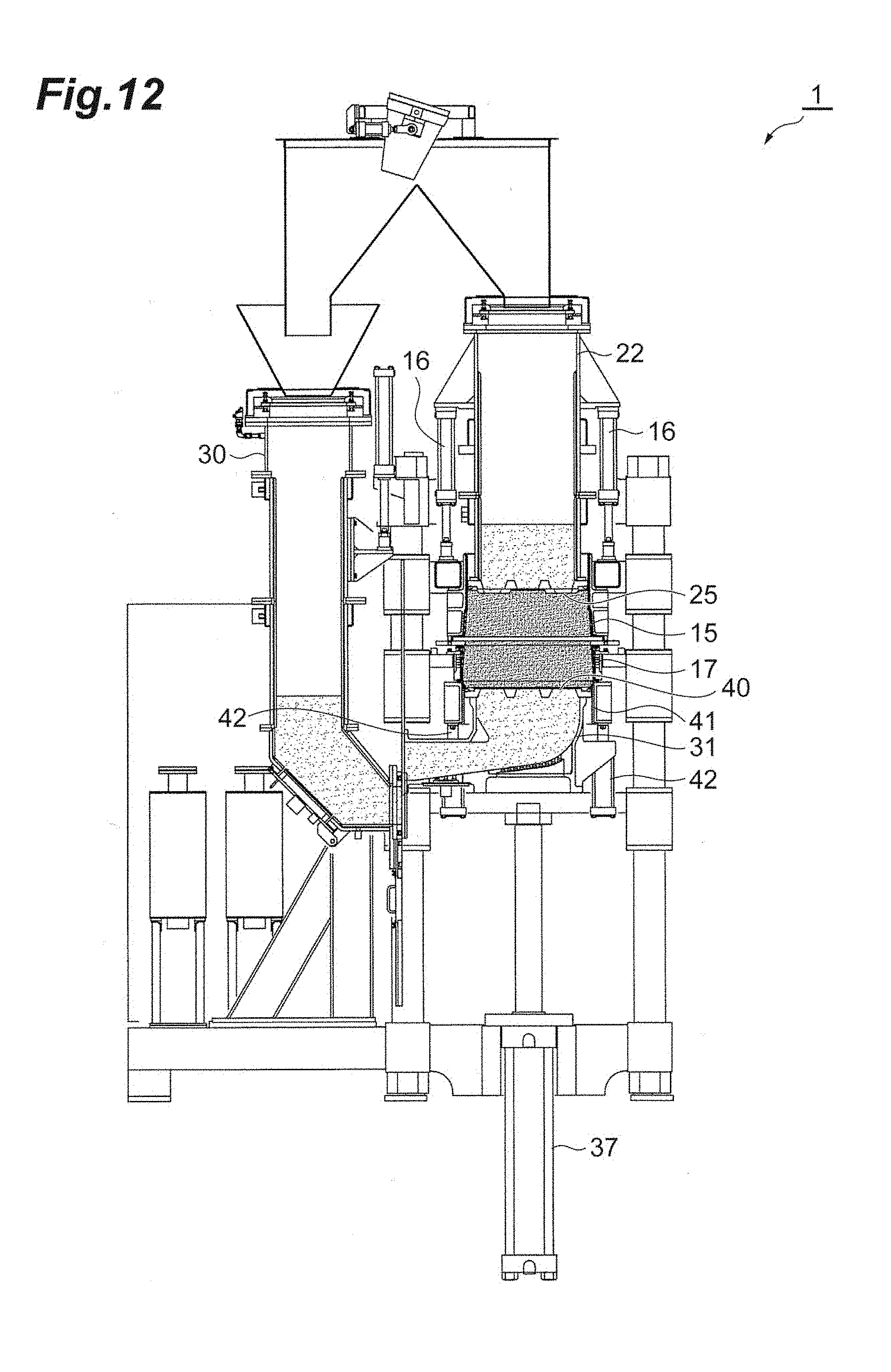
D00013
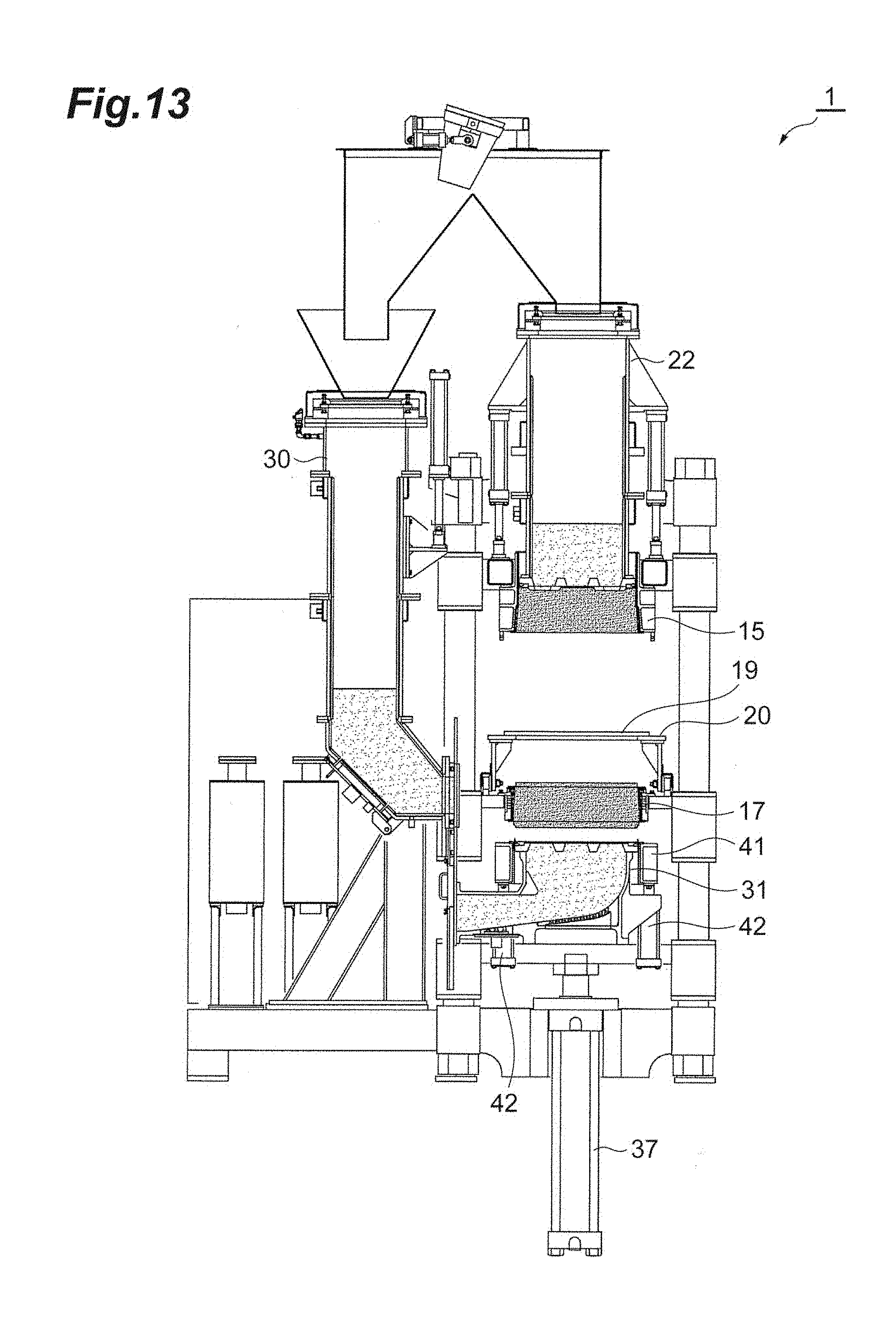
D00014
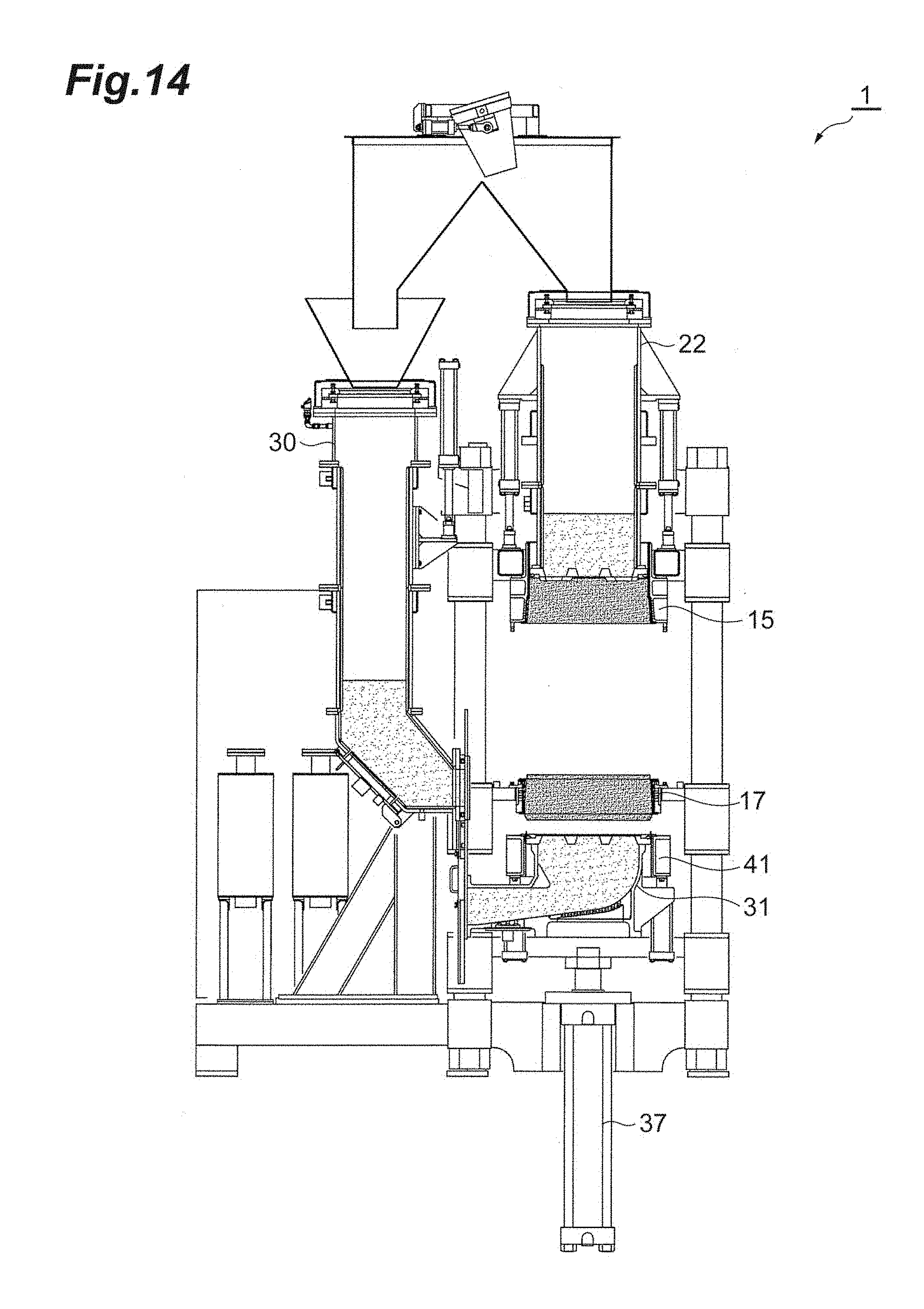
D00015
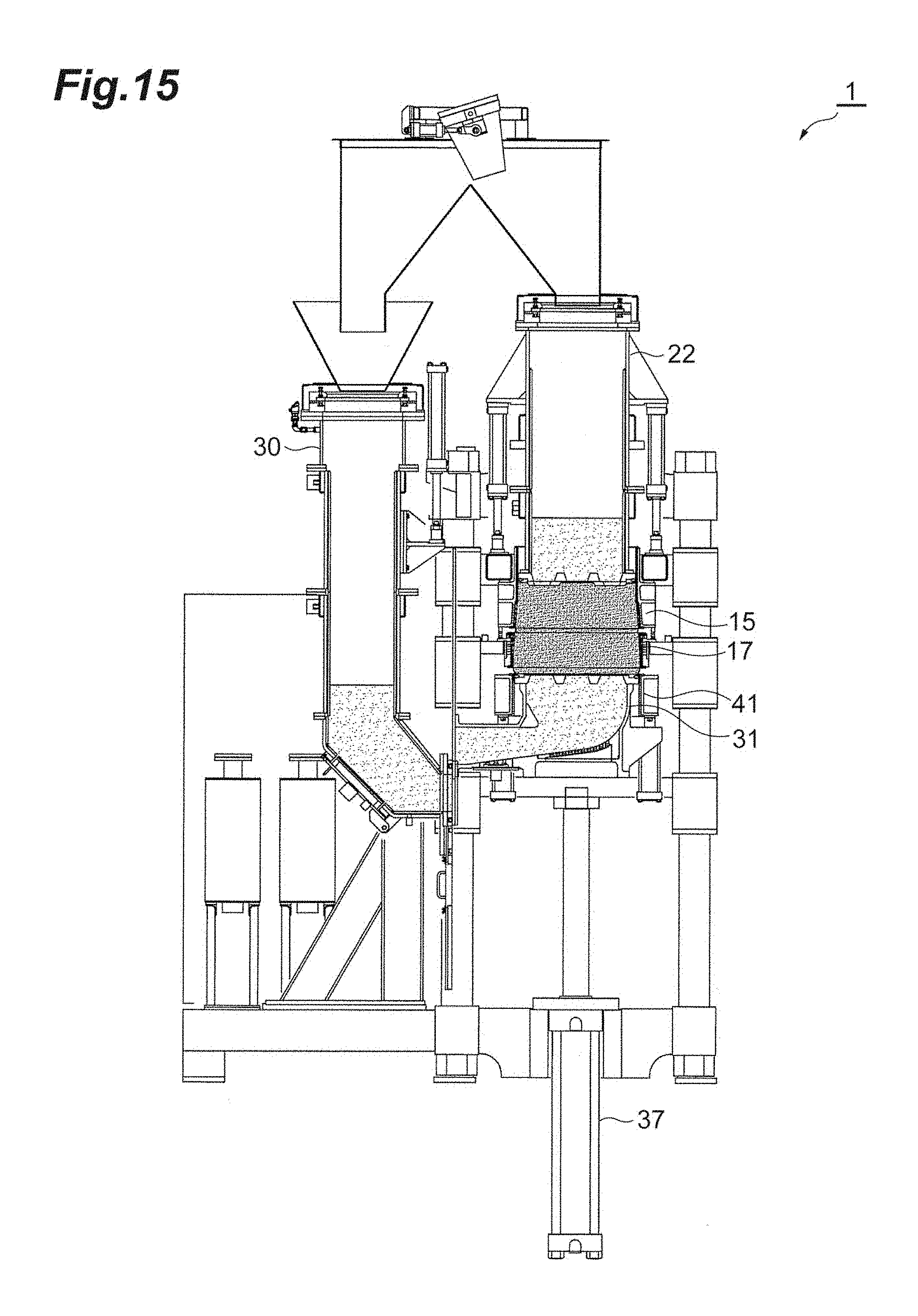
D00016
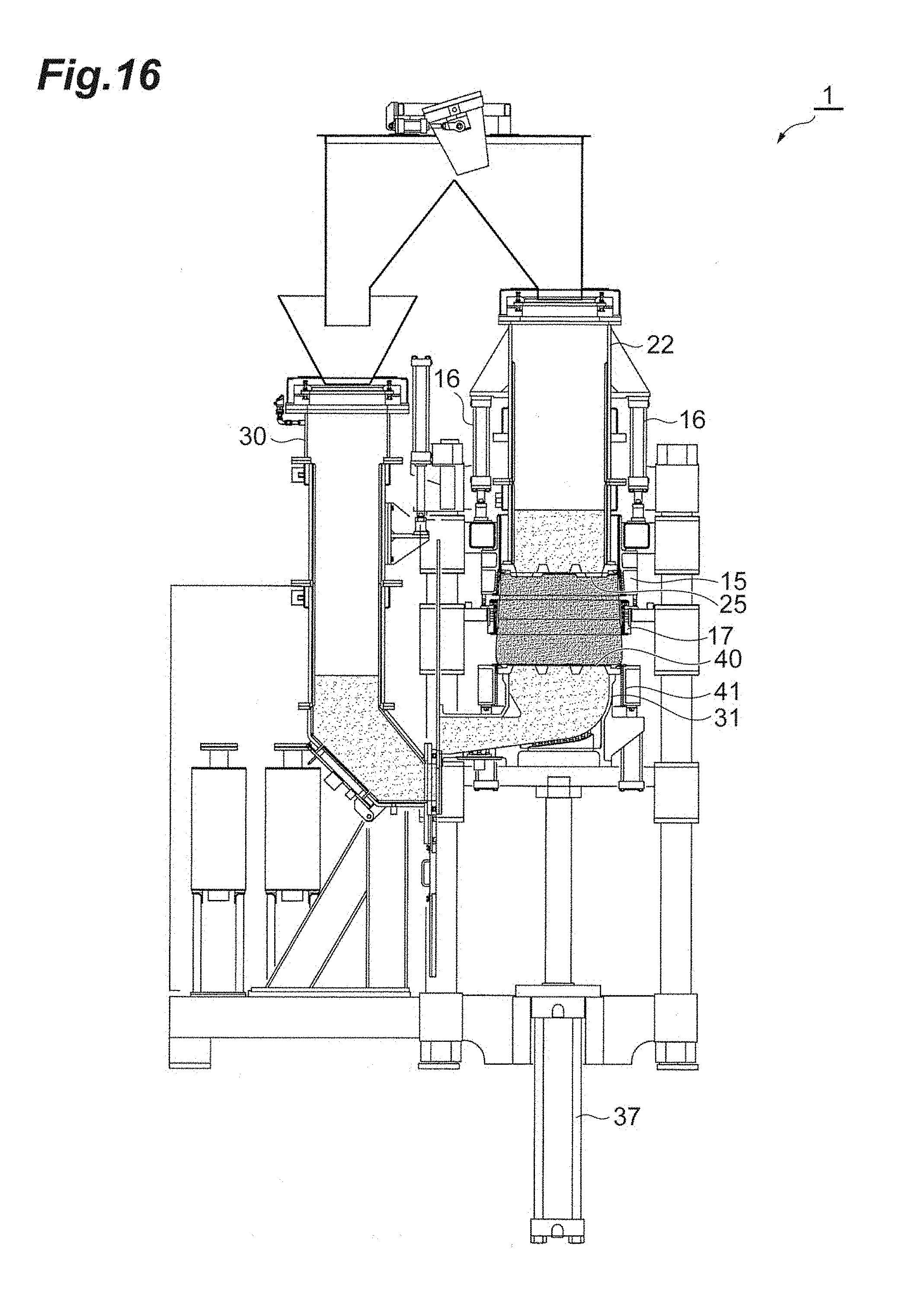
D00017
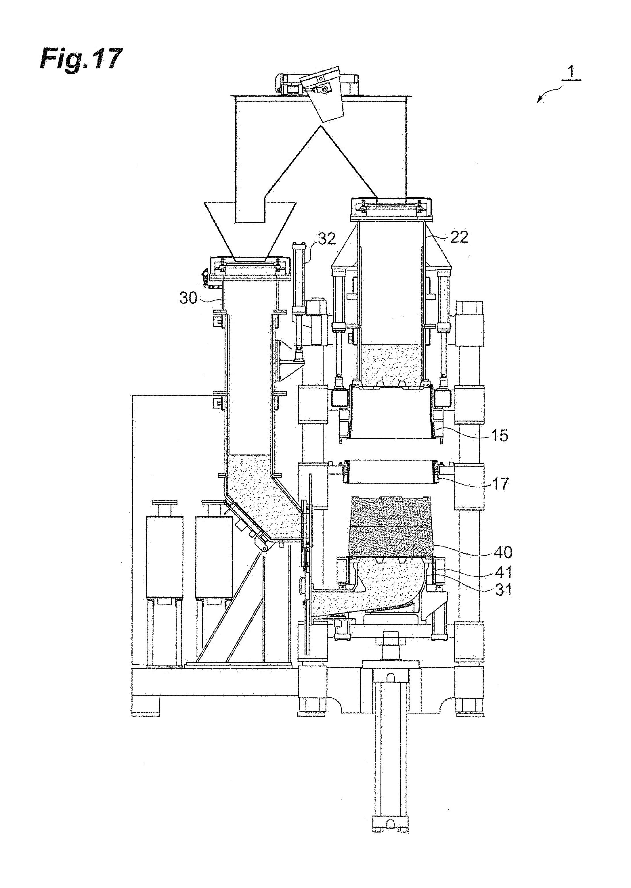
D00018
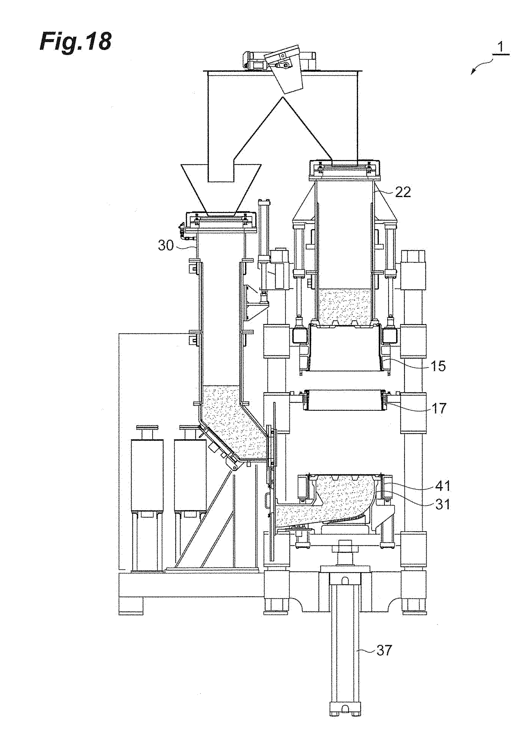
D00019
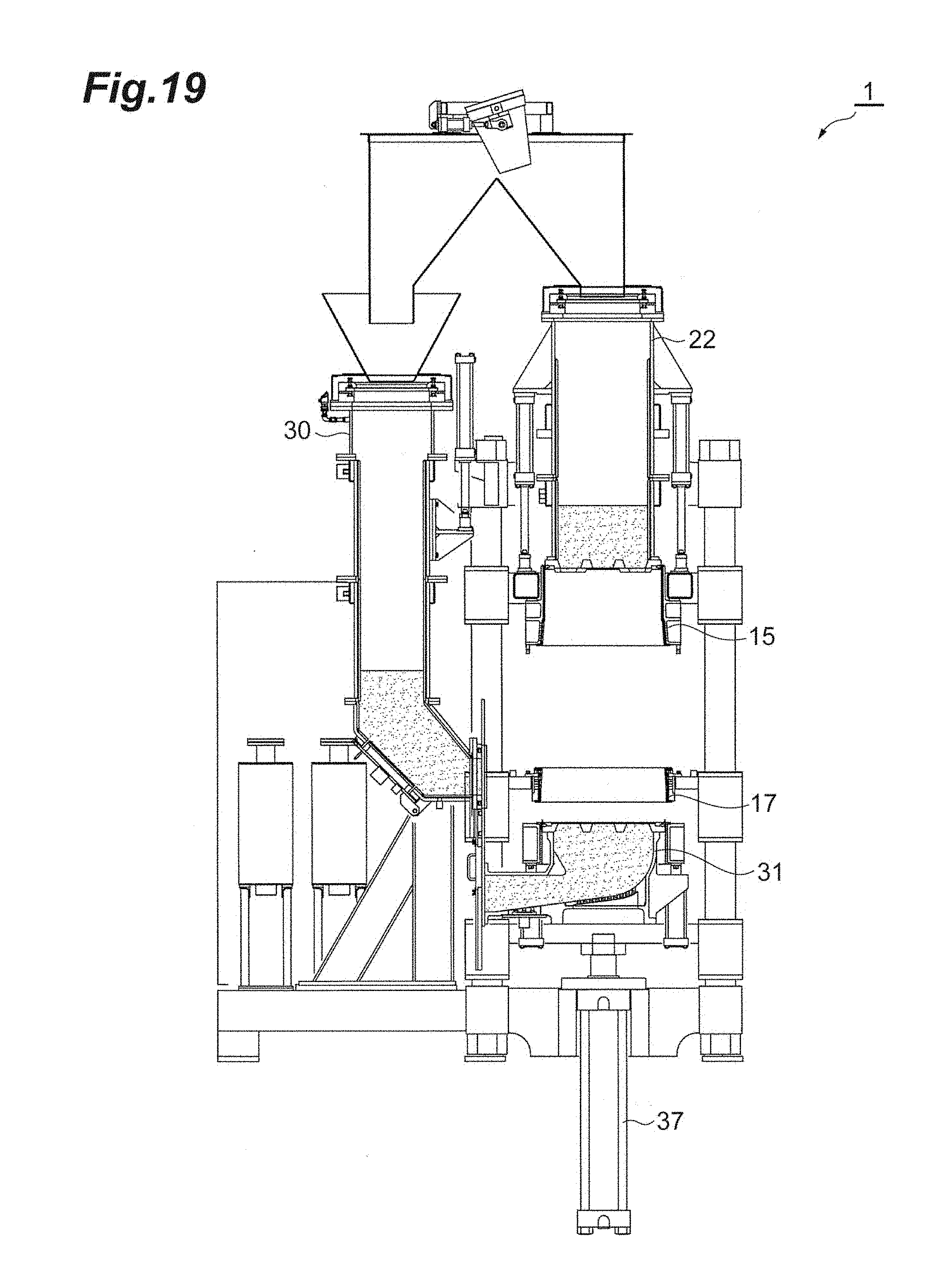
D00020
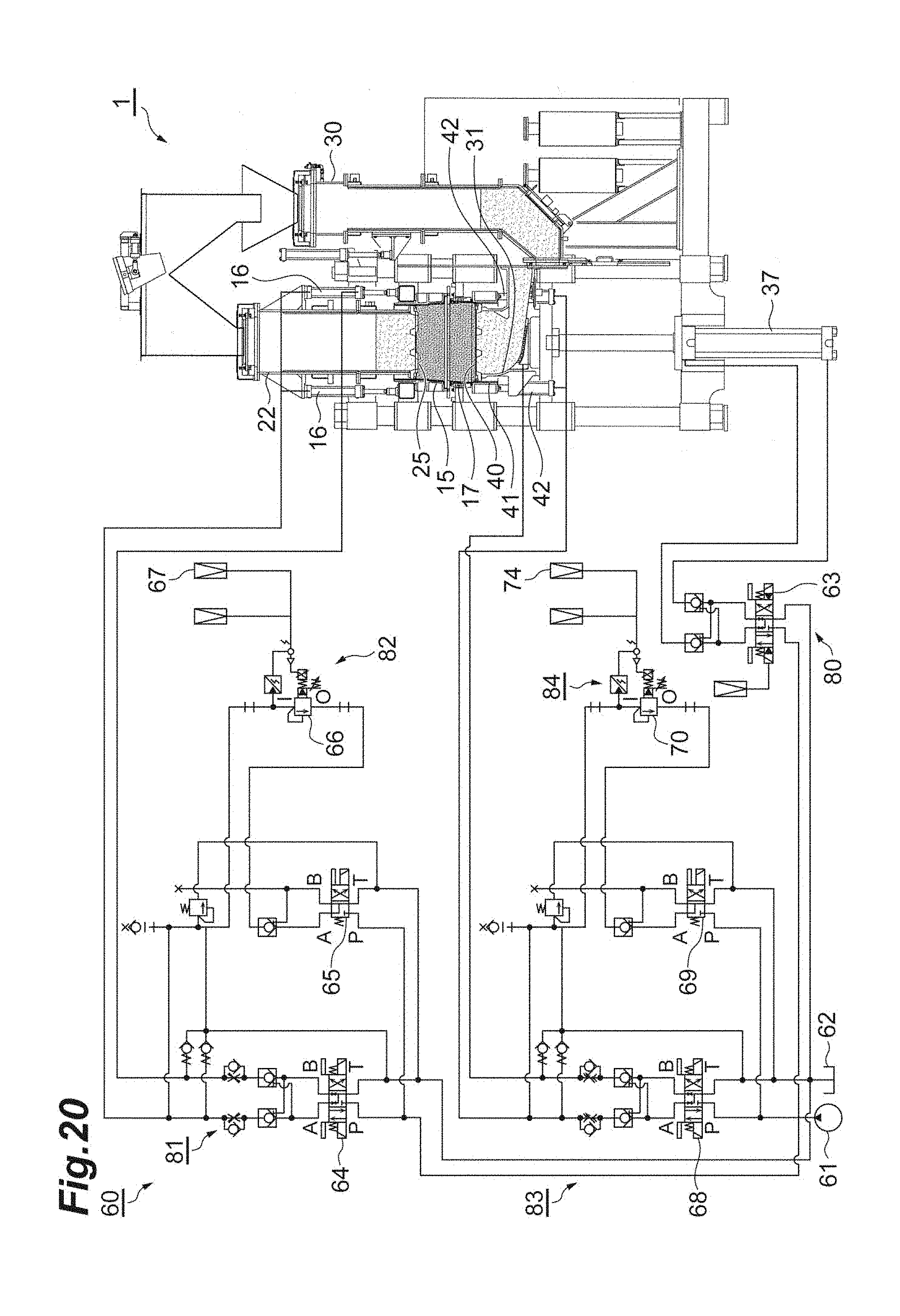
D00021
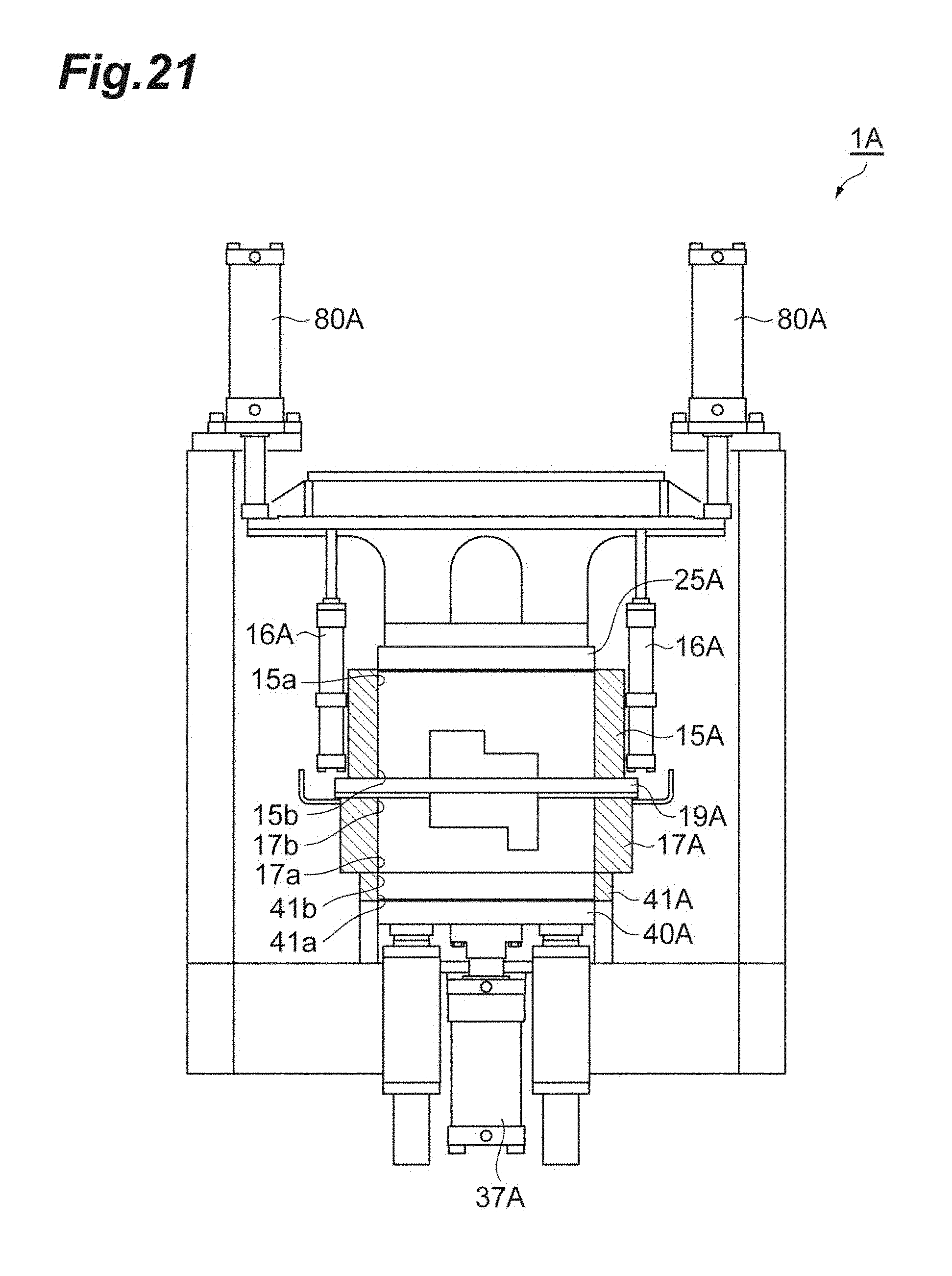
D00022
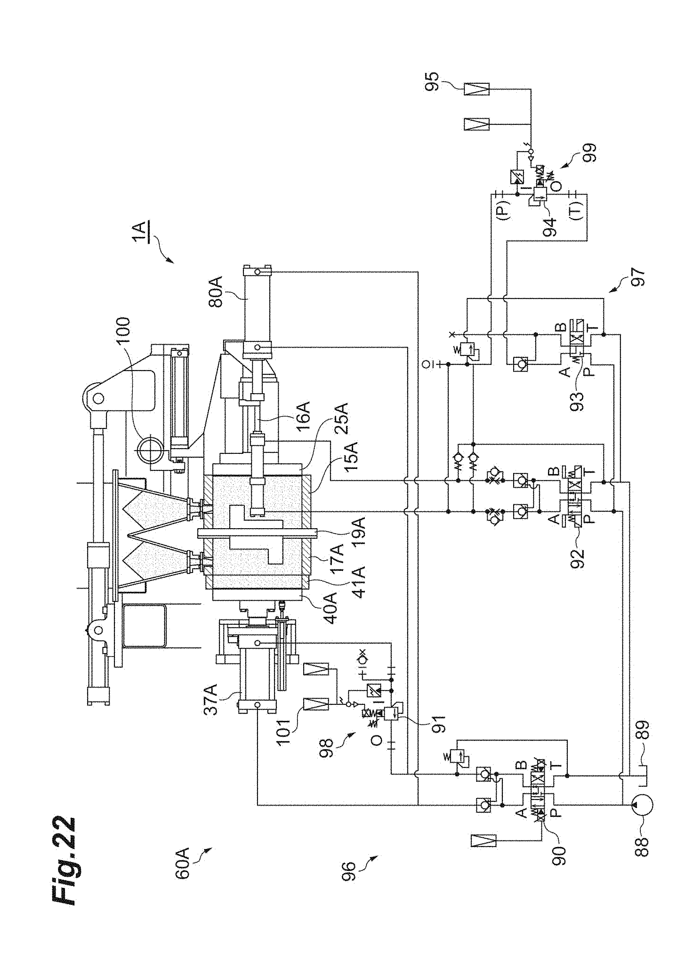
XML
uspto.report is an independent third-party trademark research tool that is not affiliated, endorsed, or sponsored by the United States Patent and Trademark Office (USPTO) or any other governmental organization. The information provided by uspto.report is based on publicly available data at the time of writing and is intended for informational purposes only.
While we strive to provide accurate and up-to-date information, we do not guarantee the accuracy, completeness, reliability, or suitability of the information displayed on this site. The use of this site is at your own risk. Any reliance you place on such information is therefore strictly at your own risk.
All official trademark data, including owner information, should be verified by visiting the official USPTO website at www.uspto.gov. This site is not intended to replace professional legal advice and should not be used as a substitute for consulting with a legal professional who is knowledgeable about trademark law.