Filter Membrane Module, And Method For Its Production
Goebbert; Christian ; et al.
U.S. patent application number 16/257824 was filed with the patent office on 2019-05-23 for filter membrane module, and method for its production. The applicant listed for this patent is NANOSTONE WATER GMBH. Invention is credited to Christian Goebbert, Manfred Volz.
| Application Number | 20190151802 16/257824 |
| Document ID | / |
| Family ID | 43857992 |
| Filed Date | 2019-05-23 |


| United States Patent Application | 20190151802 |
| Kind Code | A1 |
| Goebbert; Christian ; et al. | May 23, 2019 |
FILTER MEMBRANE MODULE, AND METHOD FOR ITS PRODUCTION
Abstract
The invention relates to a method for producing a membrane module, comprising a plurality of elongated filter elements disposed in parallel adjacent to one another, each element comprising a longitudinal channel, a housing enclosing the filter elements, and a collector chamber between the housing and the filter elements.
| Inventors: | Goebbert; Christian; (Eschau, DE) ; Volz; Manfred; (Grossrosseln, DE) | ||||||||||
| Applicant: |
|
||||||||||
|---|---|---|---|---|---|---|---|---|---|---|---|
| Family ID: | 43857992 | ||||||||||
| Appl. No.: | 16/257824 | ||||||||||
| Filed: | January 25, 2019 |
Related U.S. Patent Documents
| Application Number | Filing Date | Patent Number | ||
|---|---|---|---|---|
| 15154793 | May 13, 2016 | 10226741 | ||
| 16257824 | ||||
| 13591089 | Aug 21, 2012 | |||
| 15154793 | ||||
| PCT/EP2011/052074 | Feb 11, 2011 | |||
| 13591089 | ||||
| Current U.S. Class: | 1/1 |
| Current CPC Class: | B01D 63/063 20130101; B01D 46/543 20130101; B01D 2313/04 20130101; B01D 63/066 20130101; B01D 65/003 20130101; B01D 63/022 20130101; B01D 63/06 20130101; B01D 46/0021 20130101; B01D 63/061 20130101 |
| International Class: | B01D 63/06 20060101 B01D063/06; B01D 65/00 20060101 B01D065/00; B01D 46/00 20060101 B01D046/00; B01D 63/02 20060101 B01D063/02; B01D 46/54 20060101 B01D046/54 |
Foreign Application Data
| Date | Code | Application Number |
|---|---|---|
| Feb 22, 2010 | DE | 10 2010 008 869.2 |
| Apr 22, 2010 | DE | 20 2010 005 971.2 |
Claims
1. (canceled)
2. A filter membrane module, comprising: a plurality of membranes, each membrane comprising a plurality of longitudinal conduits; and a housing connected to and surrounding the membrane, wherein: for each of at least two of the membranes: the membrane has a cross-section in a plane that is perpendicular to the longitudinal conduits; the cross-section comprises two curved sides and two flat sides; and the two flat sides are opposite each other; and the filter membrane module is configured so that during use of the filter membrane module a medium to be filtered enters the longitudinal conduits and a filtered medium passes through a porous ceramic material of the longitudinal conduits and enters a collecting space.
3. The filter membrane module of claim 2, wherein the plurality of membranes comprises a plurality of ceramic membranes.
4. The filter membrane module of claim 2, wherein the plurality of membranes is potted within the filter membrane module.
5. The filter membrane module of claim 2, wherein each membrane has a segment of a circle cross section.
6. The filter membrane module of claim 2, wherein, for each of the at least two membranes, at least one of the flat sides is a chord of a single circle.
7. The filter membrane module of claim 2, wherein the filter membrane module has an interstice between adjacent membranes configured so that, during use of the filter membrane module, filtered medium pass through the interstice.
8. The filter membrane module of claim 2, wherein: the filter membrane module has a cross-section in a plane that is perpendicular to the longitudinal conduits; the filter membrane module has at least one axis of mirror symmetry along the cross-section; and the filter membrane module has no more than two axes of mirror symmetry along the cross-section.
9. A filter membrane module, comprising: a plurality of membranes, each membrane comprising a plurality of longitudinal conduits; and a housing connected to and surrounding the filter elements, wherein: for each membrane: the membrane has a cross-section in a plane that is perpendicular to the longitudinal conduits; and the cross-section comprises a curved side and a flat side; each of the flat sides is a chord of a single circle; and the filter membrane module is configured so that during use of the filter membrane module a medium to be filtered enters the longitudinal conduits and a filtered medium passes through a porous ceramic material of the longitudinal conduits and enters a collecting space.
10. The filter membrane module of claim 9, wherein the plurality of membranes comprises a plurality of ceramic membranes.
11. The filter membrane module of claim 9, wherein the plurality of membranes is potted within the filter membrane module.
12. The filter membrane module of claim 9, wherein each membrane has a segment of a circle cross section.
13. The filter membrane module of claim 9, wherein the filter membrane module has an interstice between adjacent membranes configured so that, during use of the filter membrane module, filtered medium pass through the interstice.
14. The filter membrane module of claim 9, wherein: the filter membrane module has a cross-section in a plane that is perpendicular to the longitudinal conduits; the filter membrane module has at least one axis of mirror symmetry along the cross-section; and the filter membrane module has no more than two axes of mirror symmetry along the cross-section.
15. A filter membrane module, comprising: a plurality of membranes, each membrane comprising a plurality of longitudinal conduits; and a housing connected to and surrounding the filter elements, wherein: the filter membrane module has a cross-section in a plane that is perpendicular to the longitudinal conduits; the filter membrane module has at least one axis of mirror symmetry along the cross-section; the filter membrane module has no more than two axes of mirror symmetry along the cross-section; and the filter membrane module is configured so that during use of the filter membrane module a medium to be filtered enters the longitudinal conduits and a filtered medium passes through a porous ceramic material of the longitudinal conduits and enters a collecting space.
16. The filter membrane module of claim 15, wherein the plurality of membranes comprises a plurality of ceramic membranes.
17. The filter membrane module of claim 15, wherein the plurality of membranes is potted within the filter membrane module.
18. The filter membrane module of claim 15, wherein each membrane has a segment of a circle cross section.
19. The filter membrane module of claim 15, wherein each membrane has at least one flat side that is a chord of a single circle.
20. The filter membrane module of claim 15, wherein the filter membrane module has an interstice between adjacent membranes configured so that, during use of the filter membrane module, filtered medium pass through the interstice.
21. The filter membrane module of claim 15, wherein: the plurality of membranes comprises a plurality of ceramic membranes; the plurality of membranes is potted within the filter membrane module; each membrane has a segment of a circle cross section; each membrane has at least one flat side that is a chord of a single circle; and the filter membrane module has an interstice between adjacent membranes configured so that, during use of the filter membrane module, filtered medium pass through the interstice.
Description
CROSS-REFERENCE TO RELATED APPLICATIONS
[0001] This application is a continuation of U.S. application Ser. No. 15/154,793 filed on May 13, 2016, which is a continuation of U.S. application Ser. No. 13/591,089 filed on Aug. 21, 2012, which is a continuation of International Application No. PCT/EP2011/052074 filed on Feb. 11, 2011, which claims the benefit of DE 10 2010 008 869.2, filed Feb. 22, 2010, and DE 20 2010 005 971.2, filed Apr. 22, 2010. The disclosures of the above applications are incorporated herein by reference.
FIELD
[0002] The present disclosure relates to a filter membrane module and a method for producing a filter membrane module.
BACKGROUND
[0003] The statements in this section merely provide background information related to the present disclosure and may not constitute prior art.
[0004] One such membrane module includes an elongated filter element, which is penetrated by at least one longitudinal conduit and comprises a porous material, such as ceramic. The module further includes a housing, which surrounds the filter element and with it forms a collection chamber.
[0005] Such a module functions as follows: Into one end of each longitudinal conduit, the medium to be treated, the so-called unfiltrate, is introduced. Along the course of the unfiltrate, filtrate passes through the wall surface of the longitudinal conduit, enters the aforementioned collection chamber between the filter element and the housing, and is carried away from there as filtrate. The unfiltrate emerges from the other end of the longitudinal conduits and is optionally returned to the first end of the longitudinal conduit, so as to form a cycle. The wall surfaces of the longitudinal conduits are coated with a material that is also permeable to a certain extent. This usually very thin film usually forms the actual filtration device.
[0006] A single filter element has a plurality of longitudinal conduits (multi-conduit element). A plurality of such multi-conduit elements is combined to form a membrane module from them.
[0007] On each face end of the filter elements, there is a face-end plate. It defines the annular chamber between the housing and the filter elements, specifically in such a way that the annular chamber is sealed off from the outer environment at least in fluid-tight fashion. Sealing it off can be problematic, since during operation varying temperatures prevail, which lead to expansion and contraction of structural parts, in fact in different ways. The face- end boundary plates may for instance be of special steel.
[0008] Exemplary embodiments have become known from EP 0 270 051 B1 and DE 690 19 552 T2. EP 1 374 979 A2 describes a filter membrane module having a multitude of spaghetti-type individual filter capillaries, which are bundled at theirs ends by means of a potting material. DE 600 24 966 T2 discloses a thermoplastic filter cartouche with a pluarility of concentric filter tubes. US 2008/0035270 A1 relates to a filter membrane module having a multitude of fibers, the ends of which are bundled by means of a potting material. US 2007/0144716 A1 describes a device with porous membranes, the ends of which being unitarily combined by potting.
SUMMARY
[0009] The object of the invention is to provide a filter membrane module having a high filter performance and offering more simple and thus cheaper manufacturing.
[0010] This object is attained by the features of the independent claims.
[0011] One fundamental concept of the invention is that a plastic potting material, such as a thermoplastic, in particular a polymer, is applied to the end region of the filter elements. The plastic thus blocks off the interstices between the filter elements. It forms a mounting ring, which in turn surrounds the filter elements in their end region.
[0012] The term "plastic" should be understood in the broadest sense. For instance, thermoset plastics or dual-component plastics such as epoxies or acrylates can be considered.
[0013] This method is performed on both ends of the bundle of filter elements, so that two mounting rings are created. Then the housing is slipped onto both mounting rings and thus onto the filter element bundle.
[0014] In an inventive multi-conduit element, a mounting ring, again comprising a plastic potting material, is first applied to one end and then to the other end of the filter element. After the application, in both cases the plastic potting material is made to harden. The same is done on the other end. Then the housing is again slipped onto the two mounting rings.
[0015] Flat membranes can be manufactured at low cost. By means of the flat and large interstices formed between the filter elements, the filtrate can be bled off very efficiently.
[0016] The housing can be formed of the same material as the mounting rings. The housing can even be in one piece with one of the two mounting rings, by being produced in a single potting operation.
[0017] In filter devices of the aforementioned structural type with ceramic filter elements, one known problem is the variably pronounced expansion under the influence of heat. This problem arises when materials with different coefficients of thermal expansion are used.
[0018] It is therefore recommended that the bearing of the housing on at least one of the mounting rings be embodied as a loose bearing, so that impermissible thermal stresses do not occur between the ceramic part and the housing.
[0019] The housing can be provided with connections for supplying or removing medium, for example for the medium to be treated (so-called unfiltrate) or for the treated medium (filtrate). If the housing is made from thermoplastic material, then potting the connection ports integrally with it is an attractive option.
[0020] Further areas of applicability will become apparent from the description provided herein. It should be understood that the description and specific examples are intended for purposes of illustration only and are not intended to limit the scope of the present disclosure.
DRAWINGS
[0021] The drawings described herein are for illustration purposes only and are not intended to limit the scope of the present disclosure in anyway.
[0022] FIG. 1 shows a single hollow ceramic fiber (spaghetti) in perspective.
[0023] FIG. 2, in an axially vertical cross section, shows three pieces of spaghetti filter elements combined in a bundle.
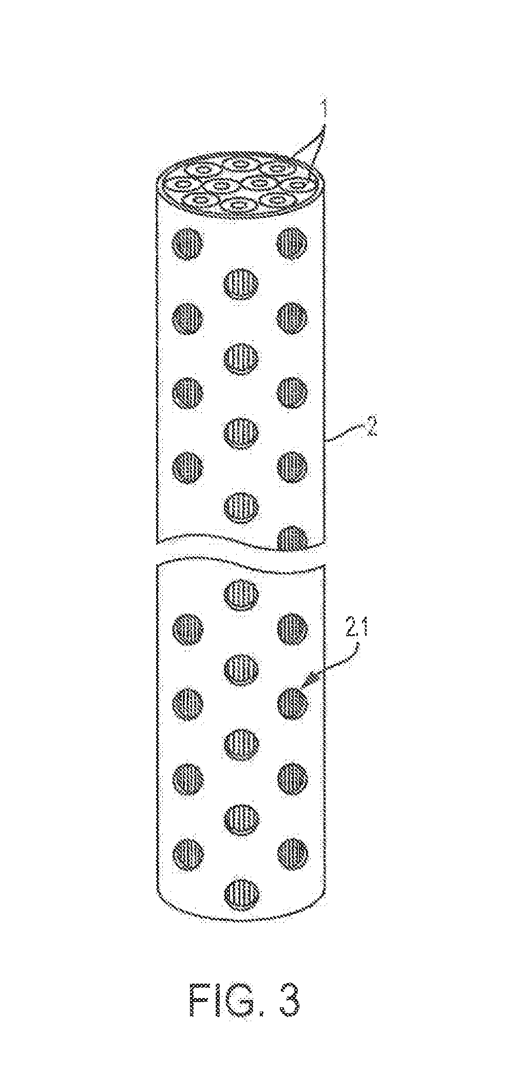
[0024] FIG. 3 shows a bundle of spaghetti filter elements surrounded by a sleeve.
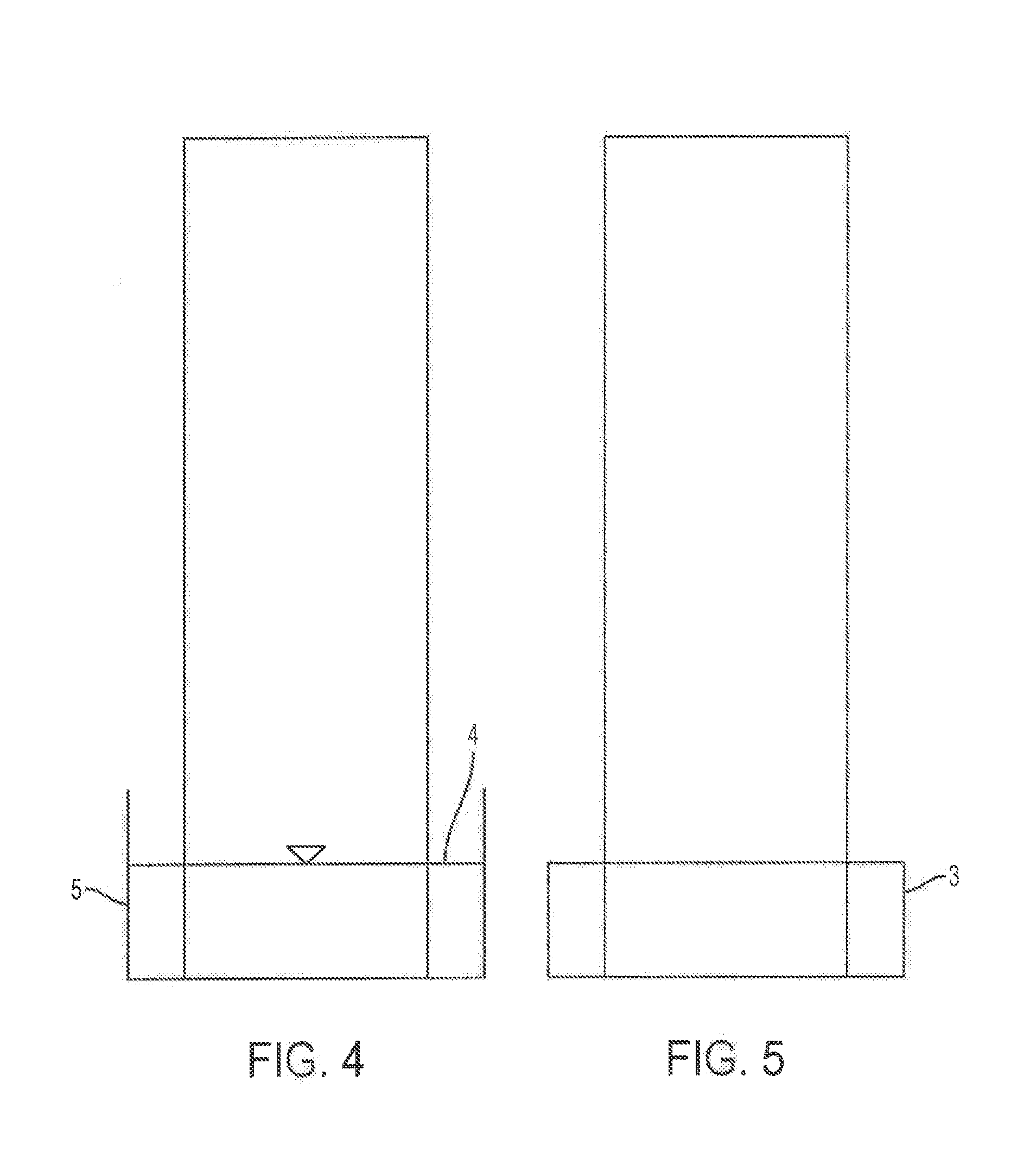
[0025] FIG. 4 schematically shows the subject of FIG. 3, with one end dipped into a tub that contains a potting material.
[0026] FIG. 5 shows the bundle with the sleeve of FIG. 3 after the potting material has hardened.
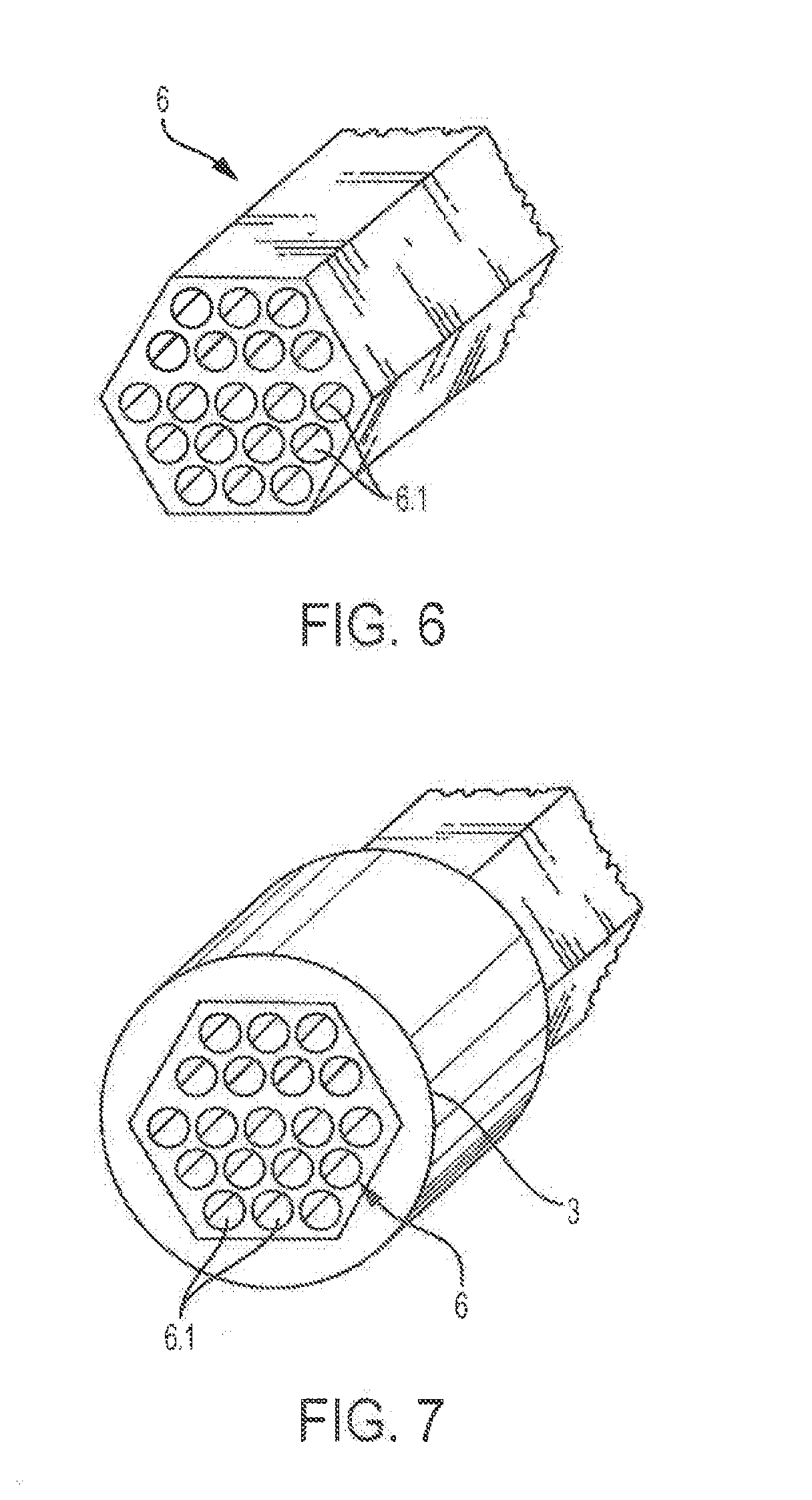
[0027] FIG. 6 shows the end region of a multi-conduit element in perspective.
[0028] FIG. 7 shows the subject of FIG. 6, provided with a mounting ring.
[0029] FIG. 8 shows the complete filter device in an elevation view and partly cut away, including a plurality of filter elements in one housing.
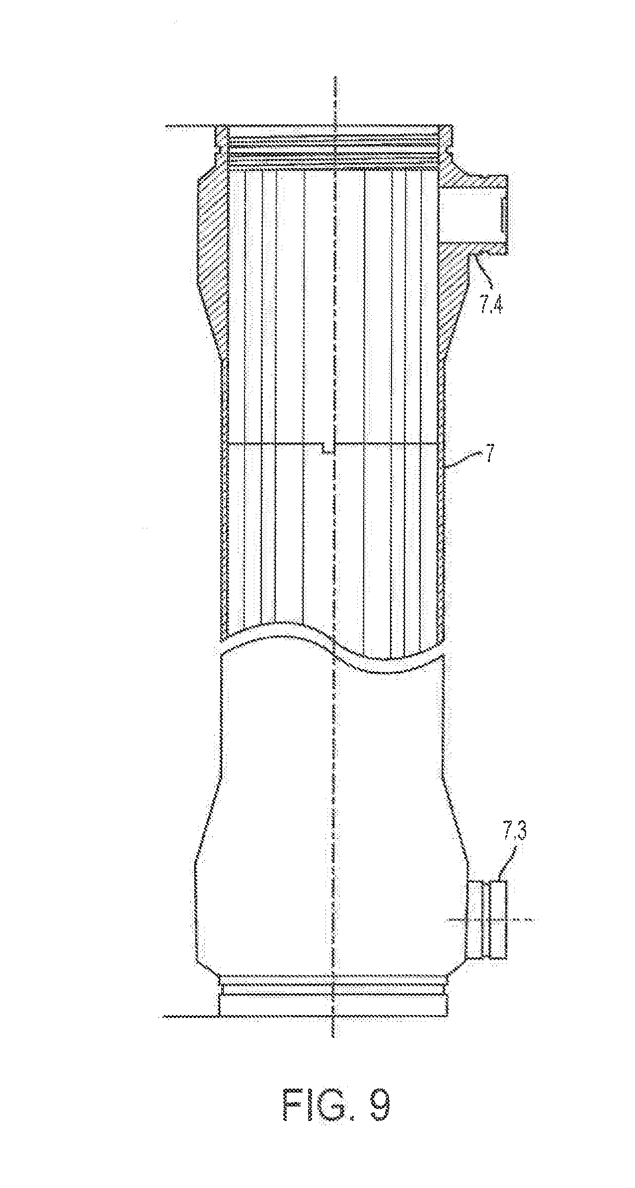
[0030] FIG. 9 shows a further filter apparatus in an elevation view and partly cut away.
[0031] FIG. 10 shows the apparatus of FIG. 9 in a plan view.
[0032] FIG. 11 shows an embodiment of an inventive filter device in cross section, with five flat membranes.
DETAILED DESCRIPTION
[0033] The following description is merely exemplary in nature and is not intended to limit the present disclosure, application, or uses. It should be understood that throughout the drawings, corresponding reference numerals indicate like or corresponding parts and features. It should also be understood that various cross-hatching patterns used in the drawings are not intended to limit the specific materials that may be employed with the present disclosure. The cross-hatching patterns are merely exemplary of preferable materials or are used to distinguish between adjacent or mating components illustrated within the drawings for purposes of clarity.
[0034] A spaghetti element 1 shown in FIG. 1 is of ceramic. It surrounds a longitudinal conduit 1.1. The spaghetti bundle shown in FIG. 2 includes three pieces of spaghetti 1, each with a longitudinal conduit 1.1. The three pieces of spaghetti enclose a hollow space 1.2 between them.
[0035] FIG. 3 shows a bundle of spaghetti 1 surrounded by a sleeve 2. The sleeve 2 has a plurality of openings 2.1, so that there is a conductive connection between the hollow spaces 1.2, each located between pieces of spaghetti 1 adjacent one another, and the external environment.
[0036] FIG. 4 schematically illustrates the application of a mounting ring 3--see also FIG. 5. For that purpose, the subject of FIG. 3 is dipped by one of its ends into a potting material 4, which is located in a tub 5. The potting material 4 comprises plastic, such as a thermoplastic material, or synthetic resin. After the subject of FIG. 3 has been dipped, the potting material penetrates through the openings 2.1 into the hollow spaces 1.2 in the spaghetti 1 and fills them up. After the potting material has hardened, the result is the subject shown in FIG. 5, that is, the spaghetti bundle, surrounded by the sleeve 2, with the mounting ring 3.
[0037] For the filtration process, it is necessary that the longitudinal conduits 1.1 remain open. This can be achieved in various ways. If the lower end face of the bundle is absolutely flat and flush with the bottom of the tub 5, then the penetration of potting material into the longitudinal conduits 1.1 can be prevented. The ends of the longitudinal conduits 1.1 could also be provided with plugs, but this is tedious and expensive. Finally, after the state shown in FIG. 5 is reached, the bundle can be shortened, by cutting off a desired piece at its lower end, since because the diameter of the longitudinal conduits is so slight, the potting material does not penetrate them overly much.
[0038] FIG. 6 shows the end region of a multi-conduit element 6 having a plurality of longitudinal conduits 6.1. The element 6 is of ceramic. It is hexagonal in cross section. Still other cross sections are also possible here, such as round or oval ones.
[0039] The application of mounting rings is done for the multi- conduit element in precisely the same way as for the spaghetti element. See FIGS. 4 and 5. However, what is crucial here is solely the application of the mounting ring 3. Conversely, it is no longer crucial to fill up hollow spaces analogously to the hollow spaces 1.2 in the bundle shown in FIG. 2.
[0040] In each case, the mounting rings 3 are seated solidly on the spaghetti bundle, or on the multi-conduit element. Now a union with a housing must be established. The finished filter apparatus is seen in FIG. 8. In it, a plurality of multi-conduit elements 6 are surrounded by a housing 7. Instead of the multi-conduit elements 6, spaghetti elements could also be provided.
[0041] The housing 7 in the embodiment shown comprises a thermoplastic material. This is the same material that comprises the mounting ring 3. The housing 7 and mounting ring 3 are produced in a single potting operation and are thus in one piece. This is true in any case for the lower mounting ring 3.1, which in a sense forms the bottom of the housing 7. It does not apply to the upper mounting ring 3.2, however. There is a seam between it and the upper end of the housing, so that an axial relative motion between the upper mounting ring 3.2 and the housing 7 is possible. It is thus also ensured that during the operation of the filter apparatus, the housing 7 can expand to different extents compared to the structural parts surrounded by the housing, namely the multi-conduit elements 6.
[0042] At this point, however, a seal is required. See the O-ring 8. This ring is let into the outer circumference of the upper mounting ring 3.2. It can already be potted integrally with the mounting ring 3.2 in the operation of potting the mounting ring.
[0043] The individual multi-conduit elements 6 are surrounded by a collection chamber 9.
[0044] The housing 7 includes a lower cap 7.1 and an upper cap 7.2. Two connection stubs, namely a lower connection stub 7.3 and an upper connection stub 7.4, are also formed integrally with the cylindrical part of the housing.
[0045] The filter apparatus of FIG. 8 functions as follows:
[0046] Through the lower cap 7.1, medium to be filtered (unfiltrate) flows to the lower face ends of the multi-conduit elements 6. There, it enters the longitudinal conduits 6.1 and flows through them. It then emerges from the upper ends of the longitudinal conduits 6.1 and reaches the upper cap 7.2.
[0047] Over this course, filtrate passes crosswise to the flow direction into the longitudinal conduits 6.1 through the porous ceramic material of the individual multi-conduit element 6 and reaches the collection chamber 9. From there, it reaches the lower outlet 7.3 and the upper outlet 7.4.
[0048] In a known manner, the unfiltrate entering the upper cap 7.2 can be carried in circulatory fashion and delivered to a further filter apparatus, or the same one, where it passes through further filtration operations.
[0049] The filtration apparatus shown in FIGS. 9 and 10 again has a housing of a thermoplastic material. The filter elements 1 are of the spaghetti type.
[0050] An alternative embodiment of a filtration apparatus, shown in FIG. 11, has a housing, not shown in this drawing, similar to that of FIGS. 9 and 10. However, the multi-conduit elements are not round ("tubular membrane") but instead are embodied in the form of five elements 6a-6e, all of them flat ("flat membranes") between which shallow, wide interstices 10 are present. The flat membranes 6a and 6e and the flat membranes 6b and 6d are embodied identically, but are disposed mirror-symmetrically to one another. Overall, the outer contours of the flat membranes 6a-6e are adapted to insertion into the tubular housing. It is understood that in other embodiments, not shown, a different number of flat membranes can also be used.
[0051] The cross sections of the two outer flat membranes 6a and 6e are in the form of classical circular segments, which are bounded on one side by a circular arc and on the other by a chord. The inner flat membranes 6b, 6c and 6d are each bounded by two circular arcs and two chords. The height h of all five flat membranes 6a-6e is identical. For the sake of simplicity, the height is shown in FIG. 11 only for the upper flat membrane 6b in FIG. 11. Here again, it is understood that in an embodiment that is not shown, still other cross sections, such as oval or even free-form cross sections, can also occur. In each flat membrane 6a-6e, there are many longitudinal conduits 6.1, of which for the sake of simplicity only one is provided with a reference numeral in FIG. 11. In the present instance, the longitudinal conduits 6.1 have an approximately square cross section, but they can have a different cross section instead.
[0052] The production and material of the embodiment of FIG. 11 are identical to the foregoing embodiments. First, the flat membranes 6a-6e are disposed in the desired manner and at the desired spacing from one another. Then the axial ends of the flat membranes 6a-6e are potted with a plastic material, as shown as an example in conjunction with a different exemplary embodiment in FIGS. 4 and 5 and described above with reference to them. The result on the axial ends is equivalent mounting rings, of which only one mounting ring 3.1 on the end is visible in FIG. 11. The plastic material on the axial ends of the flat membranes 6a-6e is also present in the interstices 10, and as a result, they are produced reliably and durably.
[0053] The function is also essentially equivalent to the function that has already been described above in conjunction with the tubular membranes 6: While the medium to be filtered is being conducted through the longitudinal conduits 6.1, the filtrate is conducted away via the interstices 10 and the interstice, between the housing and the flat membranes 6a-6e, that is formed by the mounting ring 3.1.
[0054] The description of the disclosure is merely exemplary in nature and, thus, variations that do not depart from the substance of the disclosure are intended to be within the scope of the disclosure. Such variations are not to be regarded as a departure from the spirit and scope of the disclosure.
* * * * *
D00000
D00001
D00002
D00003
D00004
D00005
D00006
D00007
D00008
XML
uspto.report is an independent third-party trademark research tool that is not affiliated, endorsed, or sponsored by the United States Patent and Trademark Office (USPTO) or any other governmental organization. The information provided by uspto.report is based on publicly available data at the time of writing and is intended for informational purposes only.
While we strive to provide accurate and up-to-date information, we do not guarantee the accuracy, completeness, reliability, or suitability of the information displayed on this site. The use of this site is at your own risk. Any reliance you place on such information is therefore strictly at your own risk.
All official trademark data, including owner information, should be verified by visiting the official USPTO website at www.uspto.gov. This site is not intended to replace professional legal advice and should not be used as a substitute for consulting with a legal professional who is knowledgeable about trademark law.