Golf Club Head With Improved Center Of Gravity
Harrington; James P. ; et al.
U.S. patent application number 16/259749 was filed with the patent office on 2019-05-23 for golf club head with improved center of gravity. This patent application is currently assigned to Acushnet Company. The applicant listed for this patent is Acushnet Company. Invention is credited to Steven J. Forshner, Oswaldo Gonzalez, James P. Harrington, Scott A. Knutson, Eddie G. Perez, Kenneth C. Scott.
| Application Number | 20190151723 16/259749 |
| Document ID | / |
| Family ID | 57111170 |
| Filed Date | 2019-05-23 |


View All Diagrams
| United States Patent Application | 20190151723 |
| Kind Code | A1 |
| Harrington; James P. ; et al. | May 23, 2019 |
GOLF CLUB HEAD WITH IMPROVED CENTER OF GRAVITY
Abstract
A golf club head with a variable center of gravity is disclosed herein. More specifically, the present invention discloses a wedge type golf club head wherein the center of gravity of the golf club head is adjustable along an x-axis in a heel to toe direction utilizing weights that are placed substantially near a sole portion of the golf club head. The resulting golf club head may generally have a more toe biased center of gravity location, especially when compared to a traditional golf club head. The present invention also discloses an innovative way to construct the golf club head to achieve those desirable center of gravity locations by utilizing various attachment techniques with different materials having different densities.
| Inventors: | Harrington; James P.; (Del Mar, CA) ; Gonzalez; Oswaldo; (San Jacinto, CA) ; Knutson; Scott A.; (Escondido, CA) ; Perez; Eddie G.; (Carlsbad, CA) ; Forshner; Steven J.; (Vista, CA) ; Scott; Kenneth C.; (San Marcos, CA) | ||||||||||
| Applicant: |
|
||||||||||
|---|---|---|---|---|---|---|---|---|---|---|---|
| Assignee: | Acushnet Company Fairhaven MA |
||||||||||
| Family ID: | 57111170 | ||||||||||
| Appl. No.: | 16/259749 | ||||||||||
| Filed: | January 28, 2019 |
Related U.S. Patent Documents
| Application Number | Filing Date | Patent Number | ||
|---|---|---|---|---|
| 15187449 | Jun 20, 2016 | |||
| 16259749 | ||||
| 14509190 | Oct 8, 2014 | |||
| 15187449 | ||||
| Current U.S. Class: | 1/1 |
| Current CPC Class: | A63B 53/0475 20130101; A63B 2053/0479 20130101; A63B 53/047 20130101; A63B 60/02 20151001; A63B 60/52 20151001; A63B 53/0408 20200801; A63B 2053/0491 20130101; A63B 53/0433 20200801 |
| International Class: | A63B 53/04 20060101 A63B053/04; A63B 60/52 20060101 A63B060/52; A63B 60/02 20060101 A63B060/02 |
Claims
1. A golf club head comprising: a chassis further comprising a hosel near a heel side of said golf club head, a striking face portion near a frontal portion of said golf club head, and a rear opening at a rear portion of said golf club head; a metallic back piece configured to at least partially fit in said rear opening, and a metallic weight pad configured to at least partially fit in said rear opening further comprising a female rivet socket, wherein said rear opening further comprises a male rivet stud protruding out from a rear surface of said rear opening, adapted to engage said female rivet socket, wherein said male rivet stud and said female rivet socket engage one another to retain said weight pad to said chassis, wherein an internal surface of said metallic back piece further comprises a plurality of back piece cutouts, adapted to receive a supplemental weight, wherein said plurality of back piece cutouts are all of different shapes, requiring different shapes of said supplemental weight depending on which specific plurality of back cutout is engaged, and a supplemental weight adapted to at least partially engage said at least one of said plurality of back piece cutouts.
2. The golf club head of claim 1, wherein said supplemental weight only partially fills said at least one of said plurality of back piece cutouts.
3. The golf club head of claim 1, wherein said supplemental weight completely fills said at least one of said plurality of back piece cutouts.
4. The golf club head of claim 1, wherein said back piece conceals said male rivet stud and said female rivet socket from view when combined with said weight pad to fill said rear opening.
5. The golf club head of claim 4, wherein said weight pad is made out of a first material having a density of greater than about 7.8 g/cm.sup.3.
6. The golf club head of claim 5, wherein at least one of said back piece or said weight pad further comprises a plurality of tabs, creating a gap between said at least one of said back piece and said chassis or said weight pad and said chassis.
7. The golf club head of claim 6, wherein both said back piece and said weight pad further comprises a plurality of tabs.
8. The golf club head of claim 7, wherein said plurality of tabs on both said back piece and said weight pad are adapted to engage said chassis.
9. The golf club head of claim 8, wherein said gap is filled with an adhesive.
10. The golf club head of claim 1, wherein said an internal surface of said weight pad further comprises a weight pad cutout, adapted to receive a supplemental weight.
11. The golf club head of claim 10, wherein, said supplemental weight only partially fills said at least one of said weight pad cutout.
12. The golf club head of claim 11, wherein said supplemental weight completely fills said at least one of said weight pad cutout.
13. A golf club head comprising: a chassis further comprising a hosel near a heel side of said golf club head, a striking face portion near a frontal portion of said golf club head, and a rear opening at a rear portion of said golf club head; a metallic back piece configured to at least partially fit in said rear opening, and a metallic weight pad configured to at least partially fit in said rear opening further comprising a female rivet socket, wherein said rear opening further comprises a male rivet stud protruding out from a rear surface of said rear opening, adapted to engage said female rivet socket, wherein said male rivet stud and said female rivet socket engage one another to retain said weight pad to said chassis, and wherein at least one of said back piece or said weight pad further comprises a plurality of tabs, creating a gap between said at least one of said back piece and said chassis or said weight pad and said chassis.
14. The golf club head of claim 13, wherein both said back piece and said weight pad further comprises a plurality of tabs.
15. The golf club head of claim 14, wherein said plurality of tabs on both said back piece and said weight pad are adapted to engage said chassis.
16. The golf club head of claim 15, wherein said gap is filled with an adhesive.
17. The golf club head of claim 16, wherein a surface area of said rear opening is substantially similar to a combined internal projected surface area of said back piece and said metallic weight pad.
18. The golf club head of claim 17, wherein said metallic weight pad is located at an upper toe portion of said golf club head.
19. The golf club head of claim 18, wherein an internal surface of said metallic back piece further comprises a plurality of back piece cutouts, adapted to receive a supplemental weight, wherein said plurality of back piece cutouts are all of different shapes, requiring different shapes of said supplemental weight depending on which specific plurality of back cutout is engaged, and a supplemental weight adapted to at least partially engage said at least one of said plurality of back piece cutouts.
20. The golf club head of claim 19, wherein said supplemental weight only partially fills said at least one of said plurality of back piece cutouts.
Description
CROSS-REFERENCE TO RELATED APPLICATIONS
[0001] The present application is a Continuation of U.S. patent application Ser. No. 15/187,449, filed on Jun. 20, 2016, which is a Continuation-In-Part (CIP) of U.S. patent application Ser. No. 14/509,190, filed Oct. 8, 2014, the disclosure of which are all incorporated by reference in their entirety.
FIELD OF THE INVENTION
[0002] The present invention relates to a golf club head with variable center of gravity. More specifically, the present invention relates to a wedge type golf club head wherein the center of gravity of the golf club head is adjustable along an x-axis in a heel to toe direction utilizing weights that are placed substantially near a sole portion of the golf club head. The weight, in one exemplary embodiment of the present invention, may be placed within a cavity that is formed at the bottom sole portion of the golf club head, while other embodiments may place the weights at different locations inside or even outside of the cavity to achieve different center of gravity locations.
BACKGROUND OF THE INVENTION
[0003] In order to improve the performance of a golf club head, golf club designers have been utilizing weighting members to adjust the center of gravity location of the golf club head. U.S. Pat. No. 2,067,556 to Wettlaufer from back in 1937 provides one of the earlier illustrations of this idea by disclosing a golf club head with a plurality of ducts extending into the club head to accommodate bodies of mercury, which alter the weight of the golf club head and adjusts the center of gravity.
[0004] U.S. Pat. No. 7,771,291 to Willett et al. issued in 2010 illustrates a modern day version of a weight adjustment mechanism for altering the center of gravity in a metalwood type golf club head. U.S. Pat. No. 7,771,291 to Willett teaches a golf club head that includes at least one weight port situated to retain weights and positioned above an approximate club face geometric center. The patent goes on to show that weights can then be applied to the weight ports in different variations, allowing an adjustment to the center of gravity of the golf club head.
[0005] Although the bigger chassis of a wood or metalwood type of golf club head makes it a more preferred chassis for using weights to adjust the center of the golf club's center of gravity, adjustment of the center of gravity can also be accomplished in an iron type golf club head having a smaller chassis as well. U.S. Pat. No. 6,015,354 to Anh et al. issued back in 2000 provides an illustration of a weighting system used to adjust the center of gravity of an iron type golf club head. More specifically, U.S. Pat. No. 6,015,354 discloses a golf club head having built-in provisions to change the weight of the golf club head including a way to increase, decrease, or adjust the position and the amount of weight in a selected golf club head to enable the player to adjust the club's center of gravity.
[0006] In fact, the idea of using weights for adjusting the center of gravity of a golf club head is so prevalent, it can even extend to wedge type golf club head as shown in U.S. Pat. No. 7,309,295 to Solari back in 2007. U.S. Pat. No. 7,309,295 teaches a golf club head for a chipper or wedge that provides a large striking area as well as selectable weight distribution. The golf club head has an open interior cavity having an enclosed lid enabling the permanent or removable fixation of weights for selectable weight distribution.
[0007] Although there are numerous attempts in the past of using weights to adjust the center of gravity of a golf club head, none of these methods focus on a way to adjust the center of gravity in a way that truly benefits a wedge type golf club head. Because the wedge is such a precise club in a golfer's arsenal, the precise center of gravity location along the x-axis, y-axis, and z-axis are all critical in its ability to perform as needed. More specifically, in the current art, there is no wedge type golf club head that allows for the center of gravity adjustment described above to be accomplished in a cleaner and aesthetically pleasing manner.
[0008] Hence, as it can be seen from above, despite all the attempts in creating a golf club having an adjustable center of gravity, none of them are capable of applying them to a wedge type golf club head in a manner that is clean, effective, and aesthetically pleasing. Ultimately, it can be seen from above that there is a need in the art for a wedge type golf club head capable of providing the center of gravity adjustment in the x, y, and z-orientations in an effective and clean way.
BRIEF SUMMARY OF THE INVENTION
[0009] One aspect of the present invention is a wedge type golf club head comprising of a striking face portion located at a frontal portion of the wedge type golf club head; a backing portion located behind the striking face portion; and a sole muscle portion located at a bottom of the wedge type golf club head between the striking face portion and the backing portion, wherein the sole muscle portion further comprises a cavity having an opening and one or more weights shaped to at least partially fit in the cavity, and wherein the wedge type golf club head has a center of gravity greater than about 28 mm from an intersection point between a hosel bore axis and a ground plane along an x-axis.
[0010] Another aspect of the present invention is a golf club head comprising of a striking face portion located at a frontal portion of the golf club head; a backing portion located behind the striking face portion; and a sole muscle portion located at a bottom of the wedge type golf club head between the striking face portion and the backing portion, wherein the sole muscle portion further comprises a cavity having an opening and one or more weights shaped to at least partially fit in said cavity, and wherein the opening of said cavity is opened towards a bottom sole portion of the sole muscle portion.
[0011] A further aspect of the present invention is a golf club head comprising of a striking face portion located at a frontal portion of the golf club head; a backing portion located behind the striking face portion; a sole muscle portion located at a bottom of the wedge type golf club head between the striking face portion and the backing portion, a weight pocket located at an upper toe portion of the backing portion of the golf club head, and a weight pad, located congruently within the weight pocket, wherein the wedge type golf club head has a center of gravity greater than about 28 mm from an intersection point between a hosel bore axis and a ground plane along an x-axis.
[0012] Another aspect of the present invention is a golf club head comprising of a chassis further comprising a hosel near a heel side of the golf club head, a striking face portion near a frontal portion of the golf club head, and a rear opening at a rear portion of the golf club head. In addition to the above, the present invention includes a back piece configured to at least partially fit in said the opening and a weight pad configured to at least partially fit in the same rear opening, wherein at least one external surface of the back piece has a curvature that identically matches at least one curvature on the weight pad. Finally, the rear opening further comprises a male rivet stud protruding out from the rear opening, and the weight pad further comprises a female rivet socket, such that the male rivet stud and the female rivet socket engage one another to retain the weight pad to the chassis.
[0013] These and other features, aspects and advantages of the present invention will become better understood with reference to the following drawings, description and claims.
BRIEF DESCRIPTION OF THE DRAWINGS
[0014] The foregoing and other features and advantages of the invention will be apparent from the following description of the invention as illustrated in the accompanying drawings. The accompanying drawings, which are incorporated herein and form a part of the specification, further serve to explain the principles of the invention and to enable a person skilled in the pertinent art to make and use the invention.
[0015] FIG. 1 shows a perspective view of a golf club head in accordance with an exemplary embodiment of the present invention;
[0016] FIG. 2 shows an exploded perspective view of a golf club head in accordance with an exemplary embodiment of the present invention;
[0017] FIG. 3 shows a perspective view of an internal structure of a golf club head in accordance with an exemplary embodiment of the present invention;
[0018] FIG. 4 shows a frontal view of a golf club head in accordance with an exemplary embodiment of the present invention;
[0019] FIG. 5 shows a perspective view of an internal structure of a golf club head in accordance with an alternative embodiment of the present invention;
[0020] FIG. 6 shows a perspective view of an internal structure of a golf club head in accordance with a further alternative embodiment of the present invention;
[0021] FIG. 7 shows a perspective view of a golf club head in accordance with another alternative embodiment of the present invention;
[0022] FIG. 8 shows an exploded perspective view of a golf club head in accordance with an alternative embodiment of the present invention;
[0023] FIG. 9 shows a perspective view of a golf club head in accordance with a further alternative embodiment of the present invention;
[0024] FIG. 10 shows a perspective view of a golf club head in accordance with a further alternative embodiment of the present invention;
[0025] FIG. 11 shows a perspective view of a golf club head in accordance with a further alternative embodiment of the present invention;
[0026] FIG. 12 shows a perspective view of a golf club head in accordance with an alternative embodiment of the present invention;
[0027] FIG. 13 shows an exploded view of a golf club head in accordance with an alternative embodiment of the present invention;
[0028] FIG. 14 shows a perspective view of a chassis of a golf club head in accordance with an alternative embodiment of the present invention;
[0029] FIG. 15 shows a perspective view of a chassis of a golf club head in accordance with an alternative embodiment of the present invention;
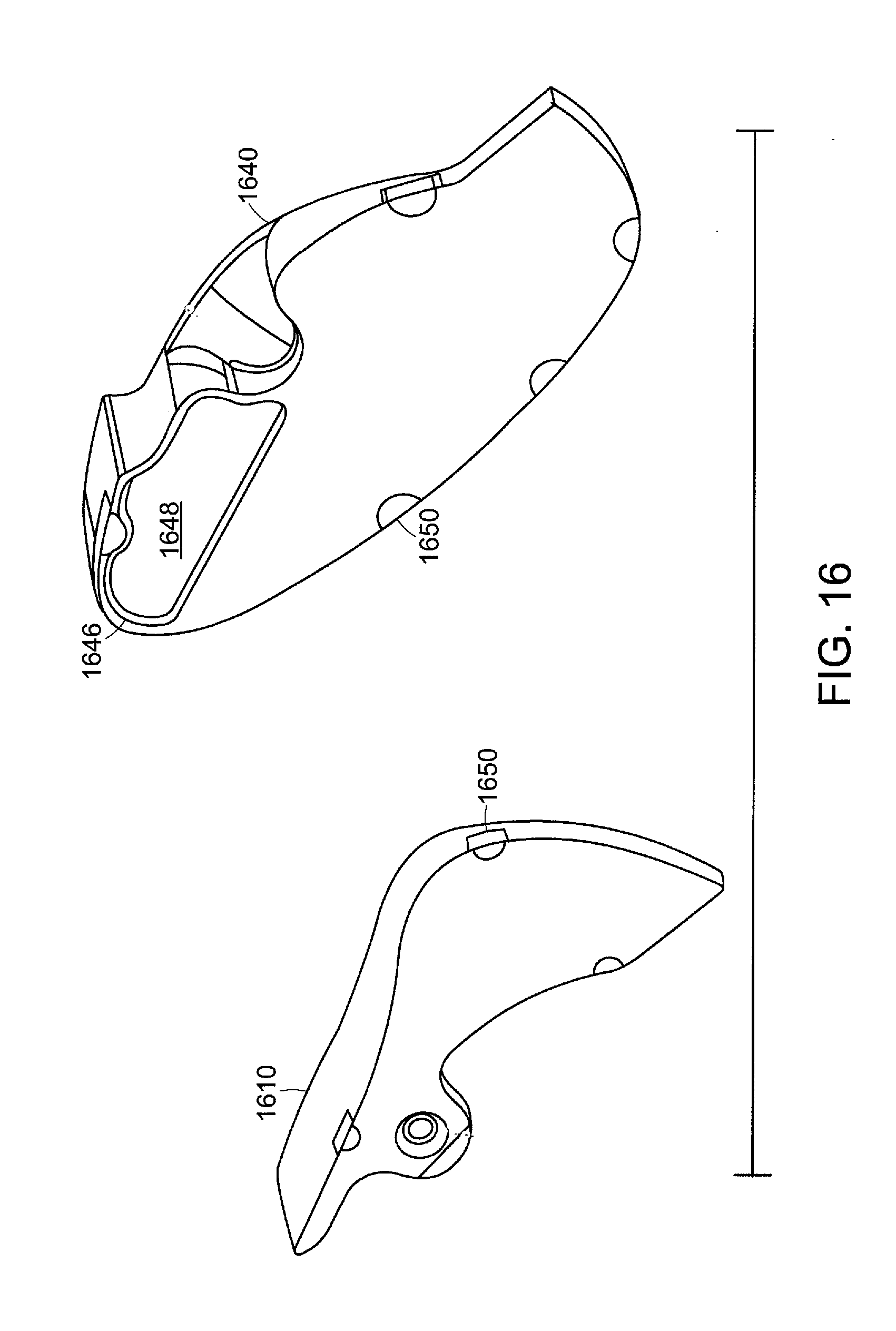
[0030] FIG. 16 shows an exploded view of an internal rear portion of a portion of a golf club head in accordance with an alternative embodiment of the present invention;
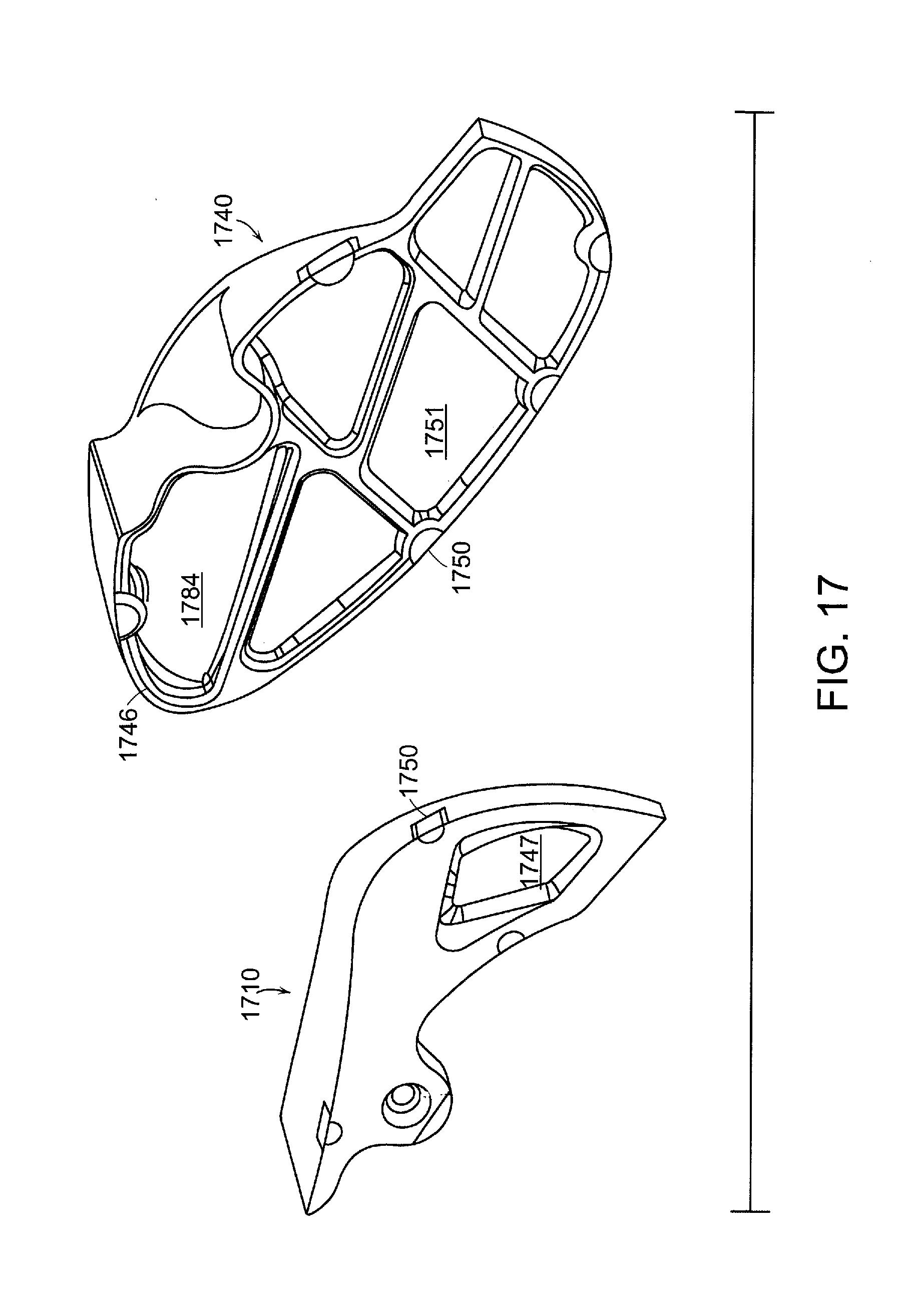
[0031] FIG. 17 shows an exploded view of an internal rear portion of a golf club head in accordance with an alternative embodiment of the present invention;
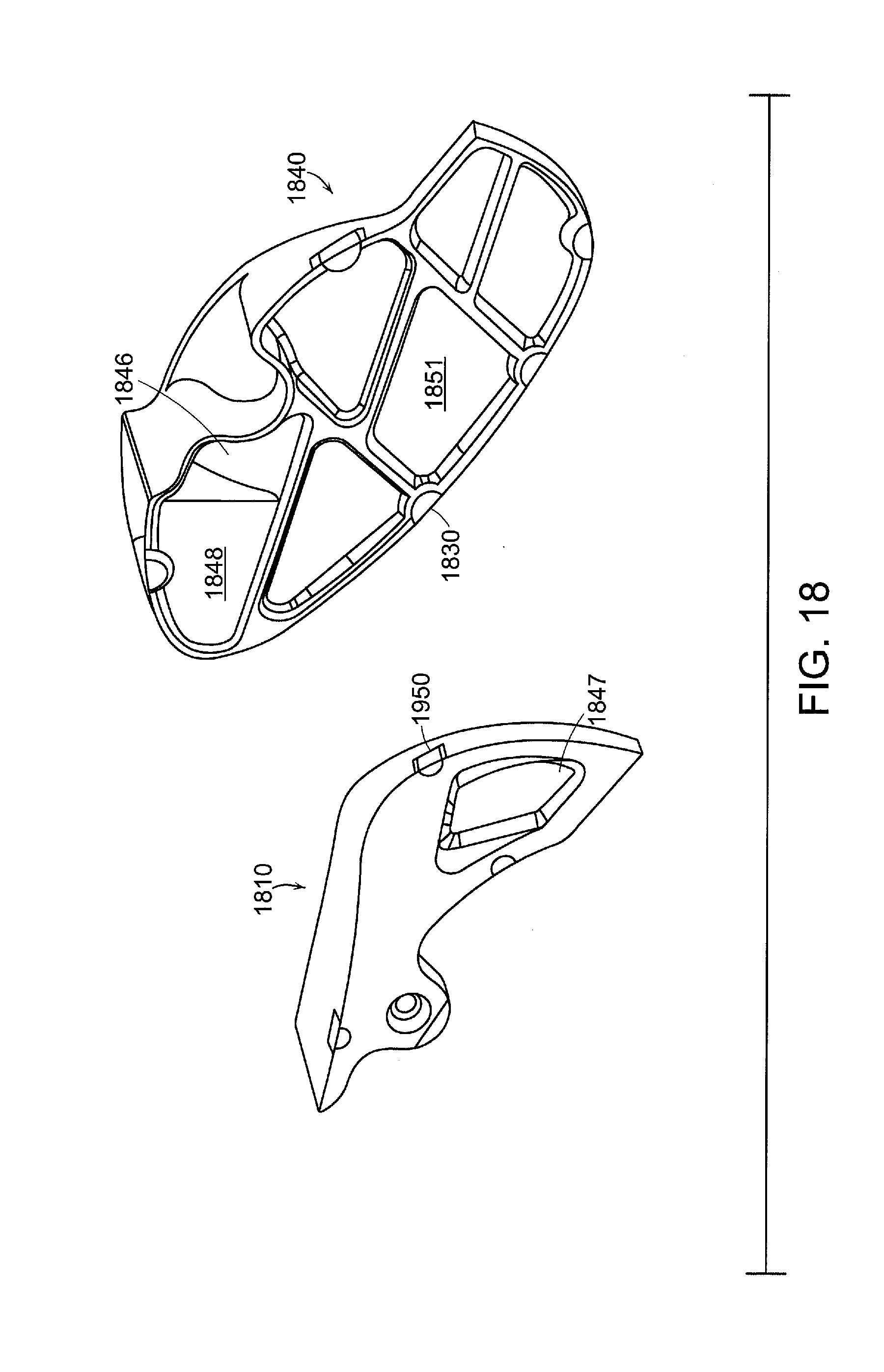
[0032] FIG. 18 shows an exploded view of an internal rear portion of a golf club head in accordance with an alternative embodiment of the present invention;
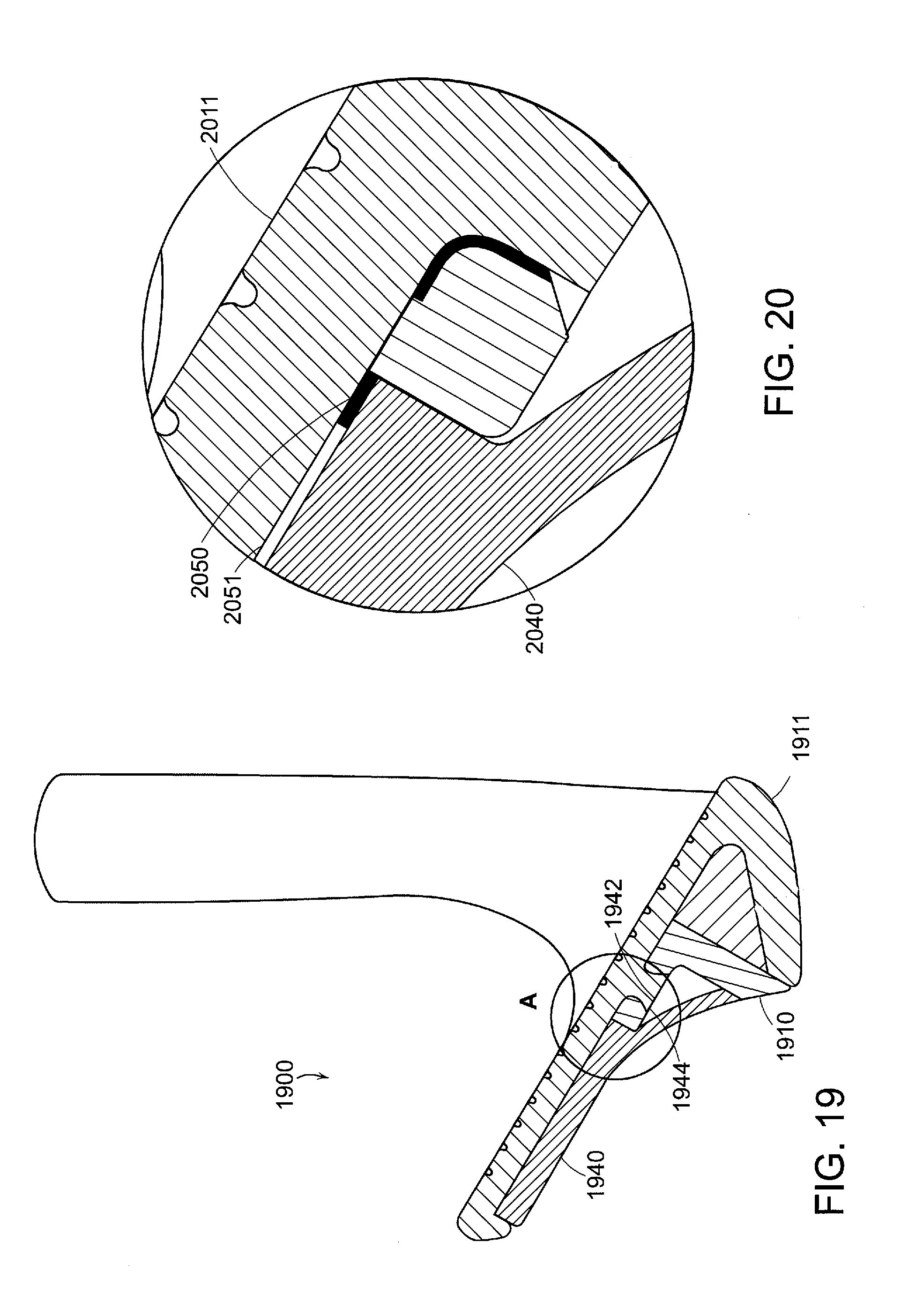
[0033] FIG. 19 shows a cross-sectional view of a golf club head in accordance with an alternative embodiment of the present invention;
[0034] FIG. 20 shows an enlarged cross-sectional view of a portion of a golf club head in accordance with an alternative embodiment of the present invention;
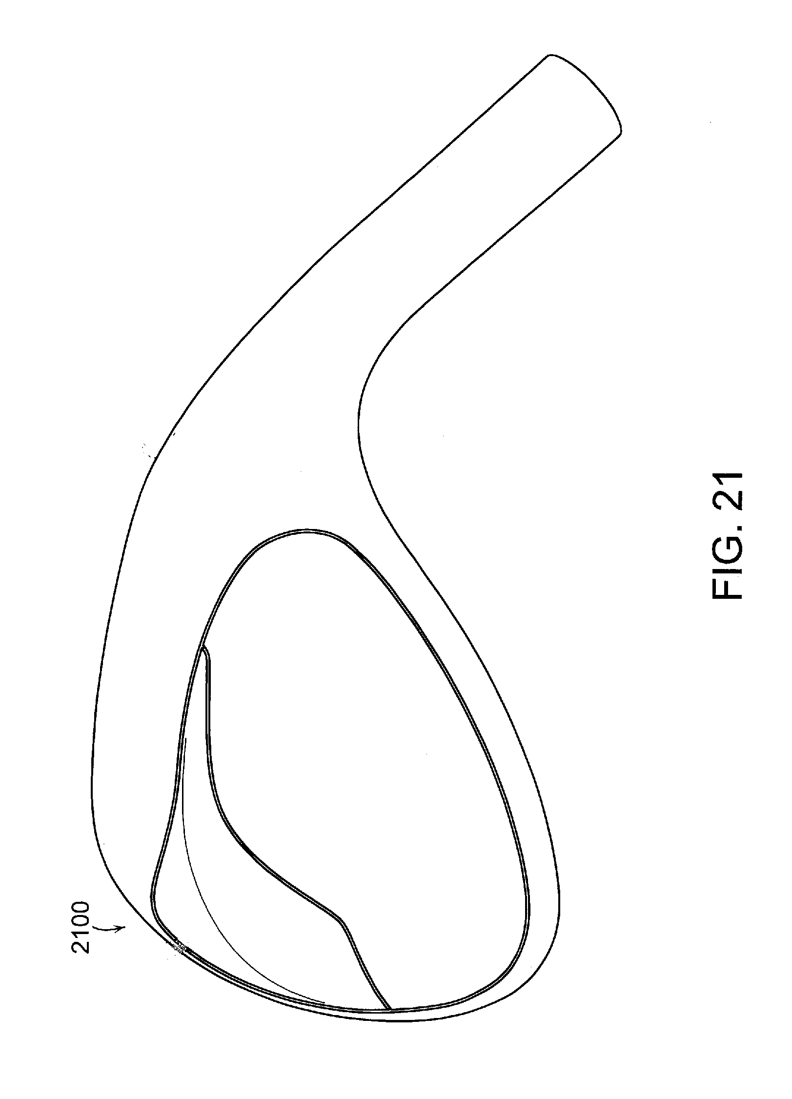
[0035] FIG. 21 shows a perspective view of a golf club head in accordance with an even further alternative embodiment of the present invention; and
[0036] FIG. 22 shows an exploded cross-sectional view of a golf club head in accordance with an even further alternative embodiment of the present invention
DETAILED DESCRIPTION OF THE INVENTION
[0037] The following detailed description describes the best currently contemplated modes of carrying out the invention. The description is not to be taken in a limiting sense, but is made merely for the purpose of illustrating the general principles of the invention, since the scope of the invention is best defined by the appended claims.
[0038] Various inventive features are described below and each can be used independently of one another or in combination with other features. However, any single inventive feature may not address any or all of the problems discussed above or may only address one of the problems discussed above. Further, one or more of the problems discussed above may not be fully addressed by any of the features described below.
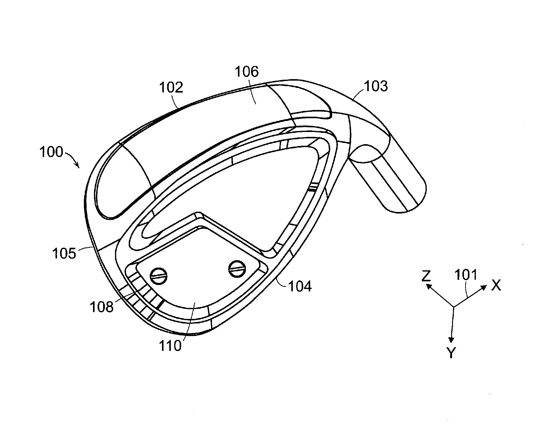
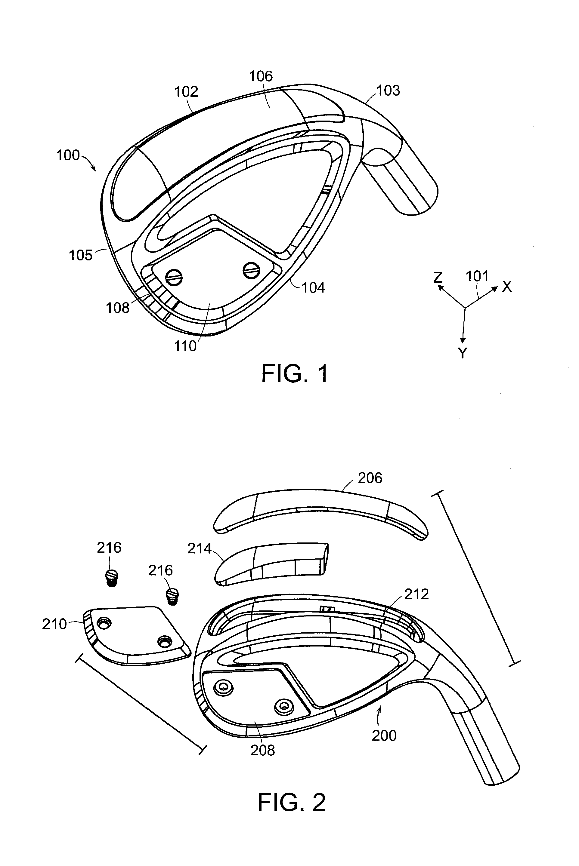
[0039] FIG. 1 of the accompanying drawings shows a perspective view of a golf club head 100 in accordance with an exemplary embodiment of the present invention. The golf club head 100 may generally have a striking face portion located at a frontal portion of the golf club head 100, a backing portion located just behind the striking face portion. The golf club head 100 may have a sole portion 102 located near a bottom "muscle portion" of the golf club head 100 and a topline portion 104 located near a top of the golf club head 100. FIG. 1 also shows the golf club having a heel portion 103 near the hosel of the golf club head 100 as well as a toe portion 105 near the extremity of the golf club head 100. The golf club head 100 in accordance with the present invention may generally have a cavity near the sole portion 102 of the golf club head where it can accommodate one or more weight members at different locations within the cavity. Because FIG. 1 shows a finished golf club head 100, the cavity is covered by up a cover 106, concealing the cavity and any weight members intended for the cavity itself. The cover 106 as shown in this current exemplary embodiment, may generally have a perimeter that is slightly smaller than the perimeter of the cavity itself, allowing room for welding material to be applied to attach the cover to the sole muscle portion of the golf club head 100. Finally, FIG. 1 also shows a weight pocket 108 located near an upper toe portion of the golf club head 100 near the back of the topline 104 of the golf club head 100. The weight pocket 108 shown in this embodiment may generally be filled with an externally exposed weight pad 110 to further help adjust the center of gravity of the golf club head 100. Alternatively speaking, it can be said that the weight pad 110 is located congruently within the weight pocket 108 to help adjust the center of gravity of the golf club head 100.
[0040] Before engaging in any further discussion regarding the structure of the golf club head, it is important here to recognize the coordinate system 101 shown in FIG. 1. The coordinate system 101 allows the orientation of the golf club head 100 to be defined, as well as setting the stage for subsequent definition of the moment of inertia about certain axis. For the purpose of this invention, the x-axis may generally refer to an axis that coincides with a heel to toe direction of the golf club head 100. The y-axis, as shown by coordinate system 101 may generally refer to the axis that goes from the top to the bottom of the golf club head 100. Finally, the z-axis may generally refer to the orientation that goes forward and backwards from the striking face portion of the golf club head 100.
[0041] FIG. 2 of the accompanying drawings shows an exploded view of a golf club head 200 in accordance with an exemplary embodiment of the present invention. The exploded view of the golf club head 200 allows the cavity 212 and the weight member 214 to be shown more clearly. It should be noted that in this exemplary embodiment, the weight member 214 is located near a toe portion of the golf club head 200 within the cavity 212 to promote a more toe biased center of gravity location. However, in alternative embodiments to be shown later, the weight member 214 could be placed near a heel portion of the cavity or a central portion of the cavity all without departing from the scope and content of the present invention. In fact, in certain embodiments, more than one weight member 214 may even be used within the cavity 212 to achieve a desired center of gravity location without departing from the scope and content of the present invention.
[0042] The exploded view of the golf club head 200 also shows the weight pocket 208 as well as the weight pad 210. Based on the location of the weight pocket 208 and weight pad 210, it can be seen that the weight pad 210 can serve to help shift the center of gravity further towards the toe portion of the golf club head 200 while at the same time raising the center of gravity higher along the y-axis. The exploded view of the golf club head 200 also shows that in the current exemplary embodiment of the present invention, the weight pad 210 may generally be secured into the weight pocket 208 via a plurality of two or more screws 216. In alternative embodiments of the present invention, the weight pad 210 may be attached to the weight pocket 208 via only one screw 216, via any other mechanical locking process, via a welding process, via a swaging process, or any other process capable of retaining the weight pad 210 without departing from the scope and content of the present invention.
[0043] FIG. 3 of the accompanying drawings shows a golf club head 300 in accordance with an exemplary embodiment of the present invention wherein the cover is removed to show the exact location of the weight member 314 within the cavity 312. The body portion of the golf club head 300 may generally be made out of steel type material with a density of approximately 7.8 g/cm.sup.3; however, numerous other materials that are have a density less than 7.8 g/cm.sup.3 such as aluminum, titanium, or the like without departing from the scope and content of the present invention. In this exemplary embodiment of the present invention, the weight member 314 may generally fit towards the toe portion of the golf club head 300, while leaving the remaining portion of the cavity hollow once the cap is placed back on. Having the weight member 314 towards the toe portion of the golf club head 300 may improve the performance of the golf club head by creating a more toe biased center of gravity location along the x-axis. Weight member 314, as shown in this current exemplary embodiment may generally be made out of a high density material such as tungsten with a density of greater than about 17 g/cm.sup.3. However, numerous other high density materials could be used depending on the desired center of gravity adjustment without departing from the scope and content of the present invention so long as it has a density greater than or equal to that of the body portion of the golf club head 300.
[0044] In the current exemplary embodiment of the present invention, the portion of the cavity 312 that is not occupied by the weight member 314 may generally remain empty and hollow to accentuate the effects of the weight member 314 in shifting the center of gravity location of the golf club head 300. However, in alternative embodiments of the present invention, the unoccupied portion of the cavity 312 may be filled with a lightweight material such as a polymer, aluminum, or any other material so long as the material has a density that is lower than that of the weighted member 314 without departing from the scope and content of the present invention.
[0045] In addition to the weight member 314, the weight pad 310 may generally also be comprised out of a high density tungsten material with a density of greater than about 17 g/cm.sup.3. Similar to the above, the exact material of the weight pad 310 is not critical, so long as it has a higher density than the body portion of the golf club head 300.
[0046] The exemplary golf club head, due to the extreme placement of the weight member 314, may also have an improved performance in the moment of inertia numbers. For example, the current inventive golf club head may have a moment of inertia about the x axis of greater than about 105 kg-mm.sup.2, a moment of inertia about the y axis of greater than about 320 kg-mm.sup.2, a moment of inertia about the z axis of greater than about 310 kg-mm.sup.2, and a moment of inertia about the shaft axis of greater than about 775 kg-mm.sup.2.
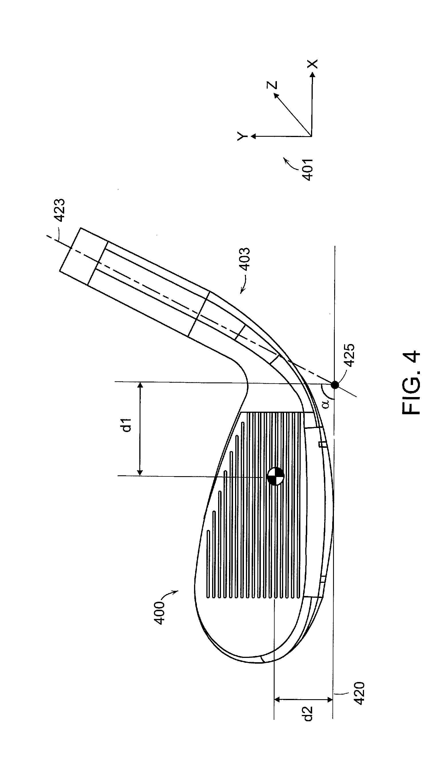
[0047] In addition to the moment of inertia numbers above, the current inventive golf club head may have a center of gravity that is significantly different from any prior art golf club head. In order to illustrate this center of gravity location, FIG. 4 is provided illustrating a frontal view of the golf club head 400 from its address position. This frontal view of the golf club head 400 allows the center of gravity 422 to be shown more clearly, as it relates to the intersect between the hosel bore axis 423 and the ground 420. The hosel bore axis 423 may generally relates to the axis centered within the bore of the hosel, and the hosel bore axis 423 intersects the ground 420 at the intersection point 425. The angle .alpha. formed between the hosel bore axis 423 and the ground 420 may generally signify the lie angle of the golf club head 400, which in terms of most wedge type golf club heads generally be about 64 degrees. In another words, the lie angle .alpha. of the current inventive golf club head 400 may generally be about 64 degrees without departing from the scope and content of the present invention.
[0048] The center of gravity 422 location, as measured from the distance of the intersection point 423 along the x-axis, may generally be at a distance d1 of greater than about 28 mm, more preferably greater than about 30 mm, and more preferably greater than about 33 mm. The center of gravity along the y-axis may generally be at a distance d2 of greater than about 20.5 mm above a ground plane 420, more preferably greater than about 21.5 mm above the ground plane 420, and most preferably greater than about 22.5 mm above the ground plane 420.
[0049] Having a center of gravity 422 location that is further away from the intersection point 425 may generally be a result of the extreme weighting that is accomplished by the current inventive golf club head 400. In a conventional golf club head, because so much weight is occupied by the hosel portion, the center of gravity 422 may generally be very close to the intersection point 425. However, in the current inventive golf club head 400, due to the extreme weighting shown in the prior figures, the center of gravity 422 may generally be further away from the intersection point 425 both along the x-axis and the y-axis.
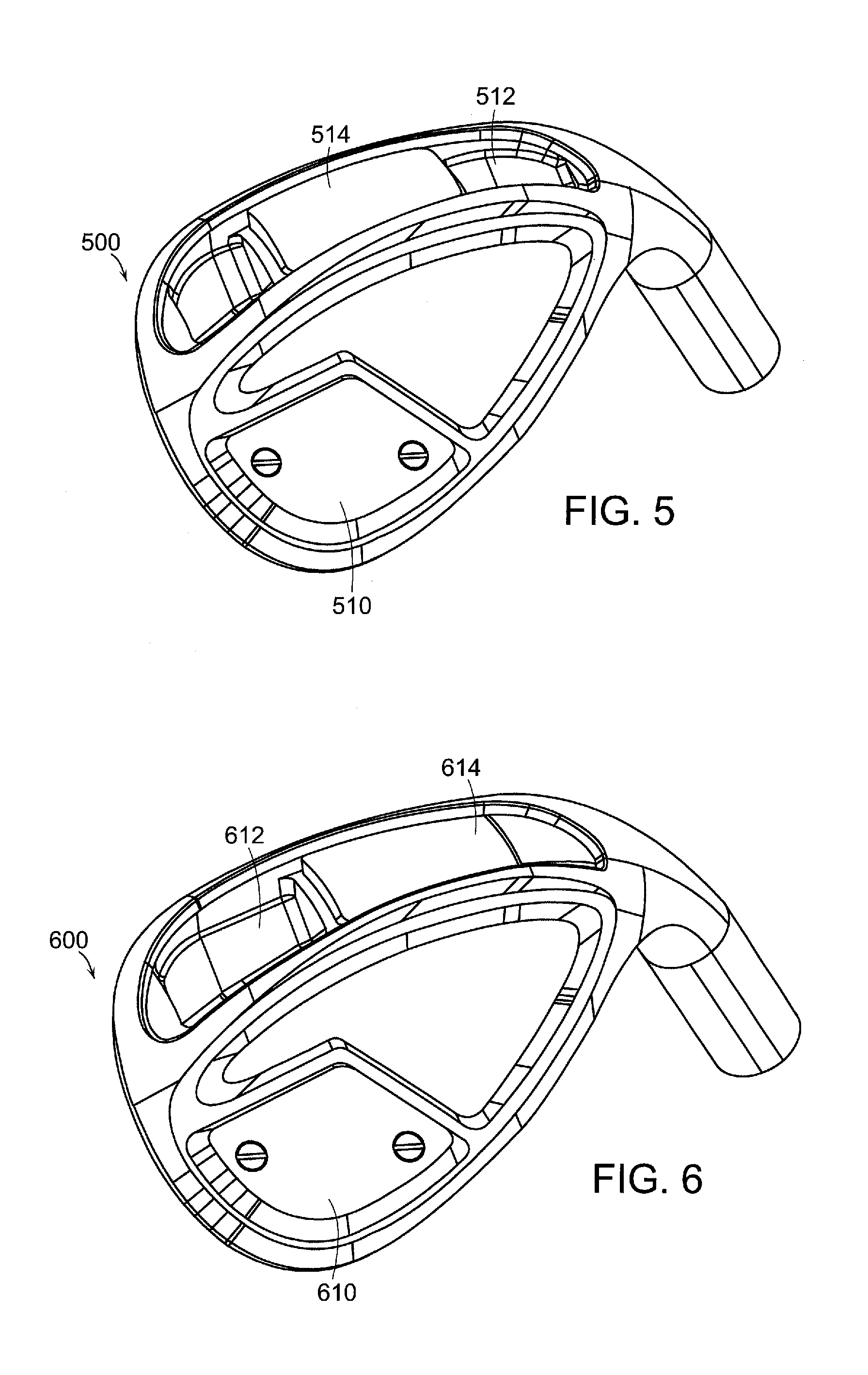
[0050] FIG. 5 of the accompanying drawings shows a perspective view of an alternative embodiment of the present invention wherein the cover is removed to show an alternative location of the weight member 514 within the cavity 512. It can be seen that the embodiment of the present invention shown in FIG. 5 is different from the embodiment shown in FIG. 3 because the placement of the weight member 514 is placed closer to the central portion of the sole, hence promoting a golf club head 500 with a more centralized center of gravity location. In this exemplary embodiment of the present invention, the golf club head may have a moment of inertia greater than about the x-axis of greater than about 100 kg-mm.sup.2, a moment of inertia about the y-axis of greater than about 300 kg-mm.sup.2, a moment of inertia about the z-axis of greater than about 300 kg-mm.sup.2, and a moment of inertia about the shaft axis of greater than about 700 kg-mm.sup.2
[0051] FIG. 6 of the accompanying drawings shows a perspective view of a further alternative embodiment of the present invention wherein the cover is removed to show an alternative location of the weight member 614 within the cavity 612. In this embodiment of the present invention the placement of the weight member 614 may be biased towards the heel portion of the golf club head 600. In this exemplary embodiment of the present invention, the golf club head may have a moment of inertia about the x-axis of greater than about 100 kg-mm.sup.2, a moment of inertia about the y-axis of greater than about 300 kg-mm.sup.2, a moment of inertia about the z-axis of greater than about 300 kg-mm.sup.2, and a moment of inertia about the shaft axis of greater than about 680 kg-mm.sup.2
[0052] In addition to the above, it can be seen that the weight member 614 could be comprised of a plurality of two or more weight pieces depending on the desired center of gravity change without departing from the scope and content of the present invention. In fact, in alternative embodiments of the present invention multiple weight pieces can be used to create the weight member 614 at different locations within the cavity 612 even if they are not concentrated at a specific location within the cavity 612.
[0053] FIG. 7 of the accompanying drawings shows a perspective view of a golf club head 700 in accordance with a further alternative embodiment of the present invention wherein the cavity 712 is located near the back side of the golf club head 700 near the sole portion instead of the bottom side of the golf club head 700. In this alternative embodiment, instead of placing weight at specific locations, a plurality of weights 714-1, 714-2, 714-3, 714-4, and 714-5 are all incorporated into the cavity 712. In this embodiment, the central weight 714-1 may help retain the remaining weights 714-2, 714-3, 714-4, and 714-5 in their respective locations when the desired weight configuration is achieved. In this embodiment, due to the fact that all 5 weights need to be present for the locking mechanism within the central weight 714-1 to work, different materials could be used for the plurality of weights. In an alternative embodiment of the present invention, the number of weights could deviate from the number articulated above to include more weights or even less weights, so long as the weights combine to fill out the entirety of the cavity. For example, the weights could be made out of different materials such as tungsten, steel, aluminum, plastic, rubber, or any other type of material that can be used to achieve a center of gravity change all without departing from the scope and content of the present invention. Finally, FIG. 7 also shows that this current embodiment of the present invention may have a weight pad 710 located near a high toe portion of the back of the golf club head 700 to further adjust the center of gravity of the golf club head 700.
[0054] FIG. 8 of the accompanying drawings shows an exploded perspective view of a golf club head 800 in accordance with the further alternative embodiment of the present invention as shown in FIG. 7. The exploded view of the golf club head 800 shown in FIG. 8 not only allows the relationship between the multiple weights 814-1, 814-2, 814-3, 814-4, and 814-5 to be shown more clearly, but it also allows the cavity 812 to be shown. A closer examination of the cavity 812 will show that the cavity 812 in addition to providing a perimeter that conforms to the geometry of the plurality of weights 814-1, 814-2, 814-3, 814-4, and 814-5, also provides additional recess 813 within the cavity 812 to further remove weight from the muscle portion of the golf club head 800. Removing weight from the muscle portion of the golf club head 800 may be desirable because it could create more discretionary mass. The discretionary mass created by the recess 813 within the cavity 812 can then be shifted to the plurality of weights 814-1, 814-2, 814-3, 814-4, and 814-5 to further adjust the center of gravity of the golf club head 800.
[0055] FIG. 9 of the accompanying drawings shows a perspective view of a golf club head 900 in accordance with a further alternative embodiment of the present invention. The golf club head 900 may have an adjustable weight member 914 that can be placed at a plurality of different locations along a horizontal guide 934 using screws that engage the screw hole 930 on the weight as well as the screw holes 932 on the guide 934. In this current embodiment shown in FIG. 9, the weight member 914 may be placed towards a heel portion of the golf club head 900 to promote a more heel biased center of gravity location.
[0056] FIG. 10 of the accompanying drawings shows a perspective view of a golf club head 1000 in accordance with a further alternative embodiment of the present invention. In this embodiment of the present invention, the golf club head 1000 may have the adjustable weight member 1014 placed towards the toe portion of the golf club head 1000, promoting a more toe biased center of gravity location.
[0057] Finally, FIG. 11 of the accompanying drawings shows a perspective view of a golf club head 1100 in accordance with a further alternative embodiment of the present invention. In this embodiment of the present invention, the golf club head 1100 may have the adjustable weight member 1114 placed towards a centralized location along the guide 1134, promoting a more neutral and centered center of gravity location.
[0058] FIG. 12 of the accompanying drawings shows a perspective view of a golf club head 1200 in accordance with an alternative embodiment of the present invention. In this exemplary embodiment of the present invention, the weight pad 1210 may be incorporated into the back portion of the golf club head 1200 blending into the contours of the rear cosmetics, creating an aesthetically pleasing look while achieving the weighting benefits desired. In addition to the weight pad 1210, FIG. 12 of the accompanying drawings also shows a back piece 1240 of the golf club head 1200 configured to compliment the weight pad 1210 to completely and congruently fill in a rear opening created by the chassis 1211 and create the back of the golf club head 1200. Alternatively speaking, it can be said that the at least one external surface of the weight pad 1210 has a curvature that identically matches at least one external surface of the back piece 1240. Please note that the curvature referred to here is the contact surface between the weight pad 1210 and the back piece 1240, not the outer surface of the components. In fact, the outer surface between the components could have different thicknesses such that there could be a step created between the different components without departing from the scope and content of the present invention.
[0059] Despite its smooth and aesthetically pleasing look, golf club head 1200 may also incorporate the extreme weighting mentioned in prior embodiments to create a more desirable CG location. To achieve this, the golf club head 1200 may incorporate multi-material technology similar to those described above. In one exemplary embodiment of the present invention, the weight pad 1210 may generally be made out of a heavy weight tungsten type material with a density of greater than about 7.8 g/cm.sup.3 to help promote the CG location described above. To further help accentuate the effects of the tungsten weight pad 1210, the back piece 1240 could be made out of a lightweight aluminum type material having a density of less than about 7.8 g/cm.sup.3. Due to the extreme weight of the weight pad 1210, the present invention utilizes an innovative bonding technique that combines traditional bonding using adhesive as well as a rivet type design. Finally, in order to create a neutral chassis 1211, the chassis 1211 of the golf club head 1200 may generally be comprised out of a material with a density of between about 2.0 g/cm.sup.3 and 8.0 g/cm.sup.3.
[0060] FIG. 13 of the accompanying drawings shows an exploded perspective view of golf club head 1300 in accordance with an alternative embodiment of the present invention wherein the interface between the various components can be shown more clearly. In this exploded perspective view, it can be seen that the rivet type design further comprises of two components, a male rivet stud 1342 being attached to the chassis 1311 within the rear opening 1313 of the chassis 1311 and a female rivet socket 1344 attached to the weight pad 1310 via a protrusion. It should be noted here that the rivet attachment mechanism is used to secure the weight pad 1310 to the chassis 1311 because the weight pad 1310 may generally be made out of a higher density material described above, and could experience more vibrations and movement of the weight when the golf club head 1300 impacts a golf ball. The current embodiment of the present invention, in addition to using the rivet described above, may actually add a layer of adhesive or epoxy to help bond the weight pad 1310 to the chassis 1311. The rivet, as referred to in this current application may cover a broader definition than one traditionally associates with a pull rivet. In fact, the rivet, as referred to in this current application, may cover an mechanism, that helps retain two components together by the deformation of the male rivet stud 1342 to expand over the female rivet socket 1344 when the male rivet stud 1342 is subjected to an external pressure.
[0061] In addition to showing the rivet attachment mechanism, FIG. 13 also shows the relationship between the back piece 1340, the weight pad 1310, and the rear opening 1313 of the chassis 1311. Due to the fact that the back piece 1340 is generally made out of a lightweight material, the back piece 1340 in this current exemplary embodiment does not generally require the usage of a rivet attachment mechanism. Rather, the attachment of the back piece 1340 to the opening 1313 of the chassis 1311 may generally be accomplished by the usage of a adhesive type substance such as epoxy.
[0062] One other feature worth noting here is that the present golf club head 1300, in order to preserve the aesthetic appearance of the golf club head 1300, has completely covered and disguised the existence of the rivet attachment mechanism from view by utilizing the back piece 1340. Alternatively speaking, it can be said that the back piece conceal the male rivet stud 1342 as well as the female rivet socket 1344 from view when combined together with the weight pad 1310 to fit inside the rear opening 1313.
[0063] Finally, the exploded view of golf club head 1300 shown in FIG. 13 also allows cavities 1312 to be shown in more detail. In this embodiment of the present invention, in order to provide more adjustability to the weighting of the golf club head 1300, the golf club head 1300 may utilize a cavity 1312 near the sole portion of the golf club head 1300 that can be filled with additional weighting elements that can further adjust the center of gravity of the golf club head 1300. In the embodiment of the present invention shown in FIG. 13, the chassis 1311 of the golf club head 1300 may have one or more cavities to further help fine tune the center of gravity location of the golf club head 1300 without departing from the scope and content of the present invention. In the embodiment shown later, the golf club could have two cavities, three cavities, or even zero cavities all without departing from the scope and content of the present invention. In order to illustrate how additional weight members (not shown in FIG. 13) can be incorporated into the weight pockets 1312, FIGS. 14 and 15 have been provided below.
[0064] FIGS. 14 and 15 of the accompanying figures shows different embodiments of the present invention wherein weight members 1414 or 1514 may be incorporated into either one of the cavities 1412 or 1512 depending on the desired center of gravity location. In FIG. 14, the weight member 1414 is incorporated into a cavity at a heel portion of the golf club head 1400, while the cavity 1412 on the toe side of the golf club head 1400 remains empty. This embodiment of the present invention could be preferred if the golf club designer needs to shift the center of gravity of the golf club head 1400 towards a heel portion of the golf club head 1400. In FIG. 15, the weight member 1514 is incorporated into a cavity at a toe portion of the golf club head 1500. Similar to the discussion above, this embodiment may be preferred if one desires a center of gravity location closer to the toe portion of the golf club head 1500. Keep in mind that although FIGS. 14 and 15 show weight members 1414 and 1514 either at the heel or toe portion of the golf club head, alternative embodiments of the present invention could incorporate weight members at either locations or none of the locations to achieve the desired center of gravity. In an even further alternative embodiments of the present invention, the weight members inserted into the cavities need not always be of high density material such as tungsten, but could be constructed out of a lightweight material such as aluminum to achieve the opposite effect all without departing from the scope and content of the present invention.
[0065] FIGS. 16 through 18 shows exploded perspective view of the weight pad 1610, 1710, and 1810 together with the back piece 1640, 1740, and 1840 to illustrate different embodiments of weight pads 1610, 1710, 1810 having a supplemental cavity 1646, 1746, and 1846 at least partially filled with a supplemental weight 1648, 1748, and 1848 in accordance with alternative embodiments of the present invention. One feature in common with all of these alternative embodiments of the present invention that allows them to be lumped together in this discussion is the feature of a supplemental cavity 1646, 1746, and 1846. In these alternative embodiments of the present invention a supplemental cavity 1646, 1746, and 1846 is created to provide further adjustment to the center of gravity location of the golf club head. In one exemplary embodiment, the supplemental cavity 1646 shown in FIG. 16 is completely filled with a higher density supplemental weight 1648, providing the maximum amount of weighting adjustment necessary. In an alternative embodiment of the present invention the supplemental cavity 1746 may be only partially filled with a supplemental weight 1748 to dial in the specific amount of weighting adjustment that is needed. In this alternate embodiment of the present invention, the supplemental weight 1748 is only partially filled at the inside of the supplemental cavity 1746. Finally, FIG. 18 shows an even further alternative embodiment of the present invention herein the supplemental weight 1848 occupies a left side on of the supplemental cavity 1846 to provide an alternate weighting placement without departing from the scope and content of the present invention; however, in another embodiments of the present invention, the supplemental weight 1848 can occupy the right side of the supplemental cavity 1846 without departing from the scope and content of the present invention.
[0066] In addition to the above, FIGS. 17 and 18 of the accompanying drawings shows additional features that may be added to alternative embodiments of the present invention to further fine tune the weighting needs of the golf club head without departing from the scope and content of the present invention. More specifically, FIGS. 17 and 18 shows two or more weight pad cutouts 1747 and 1847 at the rear internal portion of the weight pad 1710 and 1810 to further remove weight from the weight pad 1710 and 1810. It should be noted that although the intent of the weight pad cutouts 1747 and 1847 are to remove weight, they can be fitted with weighting members similar to the supplemental cavity 1746 and 1848 without departing from the scope and content of the present invention. In addition to the weight pad cutout 1747 and 1847, this embodiment of the present invention also illustrates the existence of one or more back piece cutouts 1751 and 1851 incorporated into the rear portion of the back piece 1740 and 1840. These one or more back piece cutouts 1751 and 1851 also serves to help provide fine tuning of weighting whenever needed.
[0067] It is worth noting here that in addition to the supplemental cavities 1646, 1746, and 1846 and the supplemental weight 1648, 1748, and 1848, the exploded view of the weighting mechanisms shown in FIGS. 16, 17, and 18 also allow the additional feature of a plurality of two or more tabs 1650, 1750, and 1850 to be shown in more detail. The plurality of tabs 1650, 1750, and 1850 in this exemplary embodiment of the present invention serves the purpose of creating a thin separation between either the weight pad or the back piece together with the chassis to allow a thin layer of adhesive material to fill in the gap. This thin layer of separation created by the plurality of tabs 1650, 1750, and 1850 may help increase the bond strength between the various components of the golf club head by allowing more adhesive or epoxy to be incorporated into the bonds between the different layers. The adhesive described here, in addition to help bond the different components together, may further increase the performance of the golf club head by providing dampening characteristics without departing from the scope and content of the present invention. In order to illustrate the relationship between the different components, including the plurality of tabs 1650, 1750, and 1850, cross-sectional view of the golf club head is provided.
[0068] FIG. 19 provides a cross-sectional view of a golf club head 1900 in accordance with an exemplary embodiment of the present invention. The cross-sectional view of the golf club head 1900 allows the relationship of the various components to be shown more clearly, including the chassis 1911, the back piece 1940, the weight pad 1910, as well as the male rivet stud 1942 and the female rivet socket 1944. Based on the cross-sectional view of the golf club head 1900 it can be seen that the various components all combine together to create a seamless golf club head 1900 that has significantly improved weighting adjustment capabilities all while preserving the look and feel of a traditional golf club head 1900. However, in order to really see the gap created by the tabs 1650, 1750, and 1850 discussed in the earlier example, an enlarged view of a portion of the golf club head 1900 is provided in FIG. 20.
[0069] FIG. 20 provided an enlarged cross-sectional view of a portion of a golf club head 2000 identified as circular region A. In this enlarged cross-sectional view, one of the plurality of tabs 2050 is shown more clearly to create a gap 2051 that separates the chassis 2011 from the back plate 2040. This gap 2050 may generally filled with a adhesive type material such as epoxy or any other types of adhesive all without departing from the scope and content of the present invention.
[0070] FIG. 21 shows a rear perspective view of a golf club head 2100 in accordance with an alternative embodiment of the present invention. Although this alternative embodiment of the present invention may look similar to the golf club head 1200 shown in FIG. 12 externally, the internal construction of the golf club head 2100 is significantly different. In order to see the difference, an exploded perspective view of the golf club head 2100 is shown in FIG. 22.
[0071] FIG. 22 of the accompanying shows an exploded view of golf club head 2200 showing the chassis 2211, the back piece 2240, the weight pad 2210, the cavity 2212, the male rivet stud 2242 and the female rivet socket 2244. This embodiment of the present invention, in addition to utilizing the rivet design, may also use a snap ring attachment mechanism 2254 to help retain the back piece 2240 to the chassis 2211. The golf club head 2200 in this embodiment is similar to previous embodiments in that it also uses rivets to help retain the weight pad 2210 to the chassis 2211. However, this embodiment of the present invention is different in that it utilizes one rivet mechanism and a snap ring mechanism 2254 to help retain weight member 2210 as well as the back piece 1240. In order to provide an additional layer of bonding, the present invention utilizes a through hole 2252 on the back piece 2240 to allow one of the rivet to secure two or more pieces of components to the chassis 2211. Alternatively speaking, it can be said that one rivet attachment mechanism is used to secure two or more pieces of components to the chassis without departing from the scope and content of the present invention.
[0072] Other than in the operating example, or unless otherwise expressly specified, all of the numerical ranges, amounts, values and percentages such as those for amounts of materials, moment of inertias, center of gravity locations, loft, draft angles, various performance ratios, and others in the aforementioned portions of the specification may be read as if prefaced by the word "about" even though the term "about" may not expressly appear in the value, amount, or range. Accordingly, unless indicated to the contrary, the numerical parameters set forth in the above specification and attached claims are approximations that may vary depending upon the desired properties sought to be obtained by the present invention. At the very least, and not as an attempt to limit the application of the doctrine of equivalents to the scope of the claims, each numerical parameter should at least be construed in light of the number of reported significant digits and by applying ordinary rounding techniques.
[0073] Notwithstanding that the numerical ranges and parameters setting forth the broad scope of the invention are approximations, the numerical values set forth in the specific examples are reported as precisely as possible. Any numerical value, however, inherently contains certain errors necessarily resulting from the standard deviation found in their respective testing measurements. Furthermore, when numerical ranges of varying scope are set forth herein, it is contemplated that any combination of these values inclusive of the recited values may be used.
[0074] It should be understood, of course, that the foregoing relates to exemplary embodiments of the present invention and that modifications may be made without departing from the spirit and scope of the invention as set forth in the following claims.
* * * * *
D00000
D00001
D00002
D00003
D00004
D00005
D00006
D00007
D00008
D00009
D00010
D00011
D00012
D00013
D00014
D00015

XML
uspto.report is an independent third-party trademark research tool that is not affiliated, endorsed, or sponsored by the United States Patent and Trademark Office (USPTO) or any other governmental organization. The information provided by uspto.report is based on publicly available data at the time of writing and is intended for informational purposes only.
While we strive to provide accurate and up-to-date information, we do not guarantee the accuracy, completeness, reliability, or suitability of the information displayed on this site. The use of this site is at your own risk. Any reliance you place on such information is therefore strictly at your own risk.
All official trademark data, including owner information, should be verified by visiting the official USPTO website at www.uspto.gov. This site is not intended to replace professional legal advice and should not be used as a substitute for consulting with a legal professional who is knowledgeable about trademark law.