Cinching Of Dilated Heart Muscle
Keidar; Yaron ; et al.
U.S. patent application number 16/184058 was filed with the patent office on 2019-05-23 for cinching of dilated heart muscle. The applicant listed for this patent is Valtech Cardio, Ltd.. Invention is credited to Hengchu Cao, Yaron Keidar, Nima V. Nia, Tal Reich, Stanton J. Rowe.
| Application Number | 20190151093 16/184058 |
| Document ID | / |
| Family ID | 66533797 |
| Filed Date | 2019-05-23 |


View All Diagrams
| United States Patent Application | 20190151093 |
| Kind Code | A1 |
| Keidar; Yaron ; et al. | May 23, 2019 |
CINCHING OF DILATED HEART MUSCLE
Abstract
Methods, systems, and apparatuses for treating a heart are provided. Methods can include obtaining and using an implant. One or more catheters can be used to properly position and attach the implant in a desired location in a chamber of the heart, for example, on a ventricular wall of the left ventricle between one or more papillary muscles of the left ventricle and the annulus. Then a distance along the implant or a region of the heart, for example, between the papillary muscle and the annulus, can be reduced by contracting the implant along its longitudinal axis by applying tension to a contraction member of the implant. Other embodiments are described.
| Inventors: | Keidar; Yaron; (Haifa, IL) ; Nia; Nima V.; (Mission Viejo, CA) ; Rowe; Stanton J.; (Newport Coast, CA) ; Cao; Hengchu; (Irvine, CA) ; Reich; Tal; (Moledet, IL) | ||||||||||
| Applicant: |
|
||||||||||
|---|---|---|---|---|---|---|---|---|---|---|---|
| Family ID: | 66533797 | ||||||||||
| Appl. No.: | 16/184058 | ||||||||||
| Filed: | November 8, 2018 |
Related U.S. Patent Documents
| Application Number | Filing Date | Patent Number | ||
|---|---|---|---|---|
| 62588813 | Nov 20, 2017 | |||
| Current U.S. Class: | 1/1 |
| Current CPC Class: | A61F 2250/001 20130101; A61F 2220/0016 20130101; A61F 2/2487 20130101; A61F 2220/0008 20130101; A61F 2250/0004 20130101 |
| International Class: | A61F 2/24 20060101 A61F002/24 |
Claims
1. A method for use with an implant that includes (i) an elongate sleeve defining a lumen along a longitudinal axis of the sleeve, and (ii) an elongate contraction member that extends along the sleeve, the method being for use with a heart of a subject, the method comprising: advancing a distal portion of a delivery tube into a left ventricle of the heart; advancing, within the delivery tube, the sleeve to the heart, the sleeve having a first-end portion, a second-end portion, and a mid-portion disposed longitudinally between the first-end portion and the second-end portion; within the ventricle, anchoring the sleeve in a curved path along a ventricular wall of the ventricle, such that the elongate contraction member extends outside of the sleeve between the first-end portion and the second-end portion, and a direct distance between the first-end portion and the second-end portion is shorter than a distance along the sleeve between the first-end portion and the second-end portion; subsequently, reshaping the ventricular wall by reducing the direct distance between the first-end portion and the second-end portion by pulling on the elongate contraction member such that a length of the elongate contraction member that is disposed between the first-end portion and the second-end portion becomes reduced.
2. The method according to claim 1, wherein anchoring the sleeve comprises anchoring the sleeve without capturing a chorda tendinea of the heart between the sleeve and the ventricular wall.
3. The method according to claim 1, wherein reducing the direct distance between the first-end portion and the second-end portion comprises reducing a radius of curvature of the curved path of the sleeve.
4. The method according to claim 1, wherein advancing the delivery tube into the ventricle comprises advancing the delivery tube transfemorally to the heart, transseptally into a left atrium of the heart via an interatrial septum of the heart, and into the left ventricle via a mitral valve of the heart.
5. The method according to claim 1, wherein advancing the delivery tube into the ventricle comprises advancing the delivery tube transfemorally to the heart, into a right ventricle of the heart via a tricuspid valve of the heart, and transseptally into the left ventricle via an interventricular septum of the heart.
6. The method according to claim 1, wherein advancing the delivery tube into the ventricle comprises advancing the delivery tube transapically into the ventricle.
7. The method according to claim 1, wherein advancing the sleeve to the heart comprises advancing the sleeve within the delivery tube such that, within the delivery tube, the contraction member extends outside and alongside the sleeve, between the first-end portion and the second-end portion.
8. The method according to claim 1, wherein anchoring the sleeve comprises anchoring the first-end portion to a posterior portion of the ventricular wall, and anchoring the second-end portion to an interventricular septum of the heart.
9. The method according to claim 8, wherein anchoring the sleeve further comprises anchoring the mid-portion at an apex of the heart.
10. The method according to claim 1, wherein anchoring the sleeve comprises anchoring the first-end portion to a posterior papillary muscle of the heart, anchoring the second-end portion to an anterior papillary muscle of the heart.
11. The method according to claim 10, wherein anchoring the sleeve further comprises anchoring the mid-portion at an apex of the heart.
12. The method according to claim 10, wherein anchoring the sleeve further comprises anchoring the mid-portion circumferentially around the ventricular wall.
13. The method according to claim 1, wherein reducing the direct distance between the first-end portion and the second-end portion comprises sliding the contraction member with respect to an end portion selected from the group consisting of: the first-end portion and the second-end portion.
14. The method according to claim 13, wherein the selected end portion has a housing coupled thereto, the housing defining an eyelet, and wherein sliding the contraction member comprises pulling the contraction member through the eyelet.
15. The method according to claim 14, wherein: the housing has a locking mechanism coupled thereto, the locking mechanism has an unlocked state in which the contraction member is pullable through the eyelet, and a locked state in which the locking mechanism inhibits pulling of the contraction member through the eyelet, pulling the contraction member through the eyelet comprises pulling the contraction member through the eyelet while the locking mechanism is in its unlocked state, and the method further comprises, subsequently to pulling the contraction member through the eyelet, transitioning the locking mechanism into its locked state.
16. The method according to claim 1, wherein pulling on the contraction member comprises pulling on the contraction member by actuating an adjustment mechanism coupled to the sleeve.
17. The method according to claim 16, wherein the adjustment mechanism includes a spool, and wherein actuating the adjustment mechanism comprises rotating the spool such that the contraction member collected onto the spool.
18. The method according to claim 16, further comprising, subsequently to anchoring the sleeve, advancing an adjustment tool to the adjustment mechanism, wherein actuating the adjustment mechanism comprises using the adjustment tool to actuate the adjustment mechanism.
19. The method according to claim 1, wherein anchoring the sleeve comprises progressively anchoring a plurality of sleeve-sites of the sleeve to a respective plurality of tissue sites on the ventricular wall, the plurality of sleeve-sites being distributed longitudinally along the sleeve, the plurality of sleeve sites including a first sleeve-site and a second sleeve-site, the first-end portion including the first sleeve-site, and the second-end portion including the second sleeve-site.
20. The method according to claim 19, wherein progressively anchoring the plurality of sleeve-sites comprises, for each sleeve-site of the plurality of sleeve-sites, advancing the sleeve-site out of an open distal end of the delivery tube, and driving, from inside the sleeve, a tissue-engaging element of a respective anchor through the sleeve-site and into the respective tissue site.
21-100. (canceled)
Description
CROSS-REFERENCES TO RELATED APPLICATIONS
[0001] The present application claims priority from U.S. Provisional Patent Application 62/588,813 to Keidar et al., filed Nov. 20, 2017, and entitled "Cinching of dilated heart muscle," which is incorporated herein by reference.
FIELD OF THE INVENTION
[0002] Some applications of the present invention relate in general to cardiac repair. For example, some applications of the present invention relate to reshaping the heart or portions thereof.
BACKGROUND
[0003] Ischemic heart disease and/or the shape changes of the heart can cause valvular regurgitation (e.g., mitral regurgitation). For example, this can happen by the combination of ischemic dysfunction of the papillary muscles, and the dilatation of the left ventricle that is present in ischemic heart disease, with the subsequent displacement of the papillary muscles and the dilatation of the mitral valve annulus.
[0004] Dilatation of the annulus of a native valve (e.g., the mitral valve) can prevent the valve leaflets from fully coapting when the valve is closed or should be closed. Valvular regurgitation can result in increased total stroke volume, decreased cardiac output, and heart weakening. For example, mitral regurgitation of blood from the left ventricle into the left atrium can result in increased total stroke volume and decreased cardiac output, and ultimate weakening of the left ventricle secondary to a volume overload and a pressure overload of the left atrium.
SUMMARY OF THE INVENTION
[0005] This summary is meant to provide some examples and is not intended to be limiting of the scope of the invention in any way. For example, any feature included in an example of this summary is not required by the claims, unless the claims explicitly recite the features. Also, the features described can be combined in a variety of ways. The description herein relates to systems, assemblies, methods, devices, apparatuses, combinations, etc. that may be utilized for reshaping the heart and/or a portion thereof. Various features and steps as described elsewhere in this disclosure can be included in the examples summarized here.
[0006] An implant comprising a flexible sleeve and an elongate contraction member is affixed or anchored to heart tissue (e.g., ventricular tissue), and the contraction member is subsequently tensioned in order to reshape the heart or a chamber of the heart (e.g., a ventricle or atrium).
[0007] Methods for use with an implant (e.g., the implant above or any of the implants described elsewhere herein) can include a variety of steps. For example, methods can include, and in at least one application do include, providing or obtaining the implant, which can have (i) an elongate sleeve defining a lumen along a longitudinal axis of the sleeve, and (ii) an elongate contraction member that extends along the sleeve. The methods can be for treating a heart of a subject, the heart having a right atrium, a left atrium, a mitral valve that has an annulus, and/or a left ventricle.
[0008] The various methods herein include advancing a distal portion of a catheter (e.g., a delivery catheter/tube) into a chamber of the heart. For example, advancing the distal portion of the catheter transfemorally into the left ventricle, e.g., via the mitral valve. The methods can also include, and in at least one application do include, positioning the distal portion of the catheter such that an open distal end of the catheter faces a first tissue site, the first tissue site being on a wall of a chamber of the heart (e.g., on a ventricular wall of the left ventricle) between a valve annulus and a location remote from the valve annulus (e.g., between a papillary muscle of the left ventricle and the mitral annulus). Positioning the distal portion of the catheter such that the open distal end of the catheter faces the first tissue site can include passing the distal portion of the catheter between two chordae tendineae of the heart.
[0009] The methods also include affixing or anchoring a first part of the implant and/or sleeve to the first tissue site, for example, using a first anchor or first attachment means that includes a first tissue-engaging element or portion. This can be done, for example, by passing or driving the first tissue-engaging element through the first part of the implant and/or sleeve and into the first tissue site. Affixing or anchoring the first part of the sleeve can include, and in at least one application does include, affixing or anchoring the first part of the implant and/or sleeve while the catheter remains between the two chordae tendineae.
[0010] The methods can include, and in at least one application do include, subsequently, advancing, out of the open distal end of the catheter, a second part of the implant and/or sleeve that is proximal, along the longitudinal axis, from the first part of the implant and/or sleeve, and/or repositioning the distal portion of the catheter such that the open distal end of the catheter faces a second tissue site. The second tissue site can be on a wall of a chamber of the heart (e.g., on a ventricular wall of the left ventricle) between a valve annulus and a location remote from the valve annulus (e.g., between a papillary muscle of the left ventricle and the mitral annulus, or between an annulus and a lower portion of the chamber). Repositioning the distal portion of the catheter can include, and in at least one application does include, repositioning the distal portion of the catheter without capturing a chorda tendinea of the heart between the sleeve and the ventricular wall.
[0011] The methods herein also include affixing or anchoring a second part of the implant and/or sleeve to the second tissue site using a second anchor or a second attachment means. The second anchor or second attachment means can have a second tissue-engaging element. The affixing/anchoring can be done by passing or driving the second tissue-engaging element through the second part of the implant and/or sleeve and into the second tissue site. Anchoring the second part of the implant and/or sleeve can include, and in at least one application does include, anchoring the second part of the implant and/or sleeve while the catheter remains between the two chordae tendineae.
[0012] The above steps can be repeated with additional parts of the implant and/or sleeve and additional attachment means until the implant and/or sleeve is affixed/anchored to the treatment site as desired. In one application, 2-20 parts of the implant and/or sleeve and 2-20 attachment means or anchors can be used to affix/anchor the implant and/or sleeve to 2-20 tissue sites.
[0013] The methods herein also include subsequently, reshaping the heart/chamber or reducing a distance between locations on the heart (e.g., between the papillary muscle and the annulus or annulus and a lower portion of the chamber, etc.), by contracting the implant and/or sleeve. The implant and/or sleeve can be contracted along its length or along the longitudinal axis by applying tension to the contraction member.
[0014] The methods herein can include, and in at least one application do include, advancing the first anchor or first attachment means through the catheter to the implant and into the lumen; and subsequently to affixing or anchoring the first part of the sleeve to the first tissue site, advancing the second anchor or second attachment means through the catheter to the implant and into the lumen.
[0015] Optionally, the implant can include, and in at least one application does include, a spool, and applying tension to the contraction member can include applying tension to the contraction member by rotating the spool.
[0016] The methods herein can further include, and in at least one application do include, subsequently to anchoring or affixing the second part of the sleeve, advancing an adjustment tool through the catheter to the implant. And applying tension to the contraction member can include, and in at least one application does include, applying tension to the contraction member using the adjustment tool.
[0017] The methods can further include, and in at least one application do include, identifying the subject as having heart failure with reduced ejection fraction (HFrEF). Further, advancing the distal portion of the catheter transfemorally into the left ventricle via the mitral valve can include, and in at least one application does include, advancing the distal portion of the catheter transfemorally into the left ventricle via the mitral valve responsively to the identifying.
[0018] Optionally, the catheter (e.g., delivery catheter) is a third catheter. The distal portion of the catheter can be a distal portion of the third catheter.
[0019] Advancing the distal portion of the catheter into the chamber can include, and in at least one application does include, advancing the distal portion of the catheter transfemorally into the left ventricle via the mitral valve. Further, this can include, and in at least one application does include, one or more (or all) of the following: (i) advancing a distal portion of a first catheter into the left atrium, (ii) advancing a distal portion of a second catheter out of the distal portion of the first catheter and into the left ventricle via the mitral valve; and (iii) advancing the distal portion of the third catheter out of the distal portion of the second catheter within the left ventricle. Repositioning the distal portion of the catheter can include, and in at least one application does include, repositioning the distal portion of the third catheter by withdrawing the third catheter into the second catheter.
[0020] The second catheter can include, and in at least one application does include, a plurality of second-catheter pull-wires, and advancing the distal portion of the second catheter out of the distal portion of the first catheter and into the left ventricle can include, and in at least one application does include, deflecting the distal portion of the second catheter with respect to the distal portion of the first catheter by tensioning at least one pull-wire of the second-catheter plurality of pull-wires.
[0021] The methods herein can further include, and in at least one application do include, rotationally locking the distal portion of the first catheter with respect to the second catheter, wherein deflecting the distal portion of the second catheter includes deflecting the distal portion of the second catheter while the distal portion of the first catheter remains rotationally locked to the second catheter.
[0022] The third catheter can include, and in at least one application does include, a plurality of third-catheter pull-wires, and positioning the distal portion of the catheter such that the open distal end of the catheter faces the first tissue site can include deflecting the distal portion of the third catheter with respect to the distal portion of the second catheter by tensioning at least one pull-wire of the plurality of third-catheter pull-wires.
[0023] The third catheter can be configured to be rotatable with respect to the second catheter, and the methods can further include, and in at least one application do include, rotating the third catheter with respect to the second catheter while the distal end of the third catheter is disposed in the left ventricle.
[0024] The methods herein can further include, and in at least one application do include, rotationally locking the distal portion of the second catheter with respect to the third catheter, and deflecting the distal portion of the third catheter can include, and in at least one application does include, deflecting the distal portion of the third catheter while the distal portion of the second catheter remains rotationally locked to the third catheter.
[0025] The first catheter can include, and in at least one application does include, a plurality of first-catheter pull-wires, and the methods can further include, and in at least one application do include, deflecting the distal portion of the first catheter with respect to an immediately-proximal portion of the first catheter by tensioning at least one pull-wire of the plurality of first-catheter pull-wires.
[0026] The methods herein can further include, and in at least one application do include, rotationally locking the distal portion of the first catheter with respect to the second catheter, and deflecting the distal portion of the second catheter can include, and in at least one application does include, deflecting the distal portion of the second catheter while the distal portion of the first catheter remains rotationally locked to the second catheter.
[0027] Repositioning the distal portion of the catheter such that the open distal end of the catheter faces the second tissue site can include, and in at least one application does include, deflecting again the distal portion of the third catheter with respect to the distal portion of the second catheter by tensioning at least one pull-wire of the plurality of third-catheter pull-wires.
[0028] The methods herein can further include, and in at least one application do include, advancing the first anchor to the implant and into the lumen via a channel that extends through the catheter and into the lumen, and anchoring the first part of the sleeve can include, and in at least one application does include, anchoring the first part of the sleeve while a distal end of the channel is disposed at the first part of the sleeve.
[0029] The methods herein can further include, and in at least one application do include, partially withdrawing the channel from the lumen such that the distal end of the channel becomes disposed at the second part of the sleeve, and this can be done subsequently to anchoring the first part of the sleeve, and prior to anchoring the second part of the sleeve. Further, anchoring the second part of the sleeve can include, and in at least one application does include, anchoring the second part of the sleeve while the distal end of the channel is disposed at the second part of the sleeve.
[0030] For some applications, methods for treating a subject/subject's heart or for use with an implant include providing or obtaining the implant. The implant can be the same as or similar to other implants described in this disclosure, for example, the implant can include (i) an elongate sleeve defining a lumen along a longitudinal axis of the sleeve, and (ii) an elongate contraction member that extends along the sleeve.
[0031] The various methods herein can include, and in at least one application do include, one or more or all of the following steps:
[0032] advancing a distal portion of a delivery tube/delivery catheter into a chamber of the heart (e.g., left ventricle);
[0033] advancing, within the delivery tube, a sleeve to the heart, the sleeve having a first-end portion, a second-end portion, and a mid-portion disposed longitudinally between the first-end portion and the second-end portion;
[0034] within the chamber (e.g., ventricle), affixing or anchoring the sleeve in a curved path along a wall (e.g., ventricular wall) of the chamber (e.g., ventricle). This can be done such that an elongate contraction member extends outside of the sleeve between the first-end portion and the second-end portion, and a direct distance between the first-end portion and the second-end portion is shorter than a distance along the sleeve between the first-end portion and the second-end portion;
[0035] reshaping the wall of the chamber (e.g., ventricular wall) by reducing the direct distance between the first-end portion and the second-end portion by pulling on the elongate contraction member such that a length of the elongate contraction member that is disposed between the first-end portion and the second-end portion becomes reduced.
[0036] Affixing or anchoring the sleeve can include affixing or anchoring the sleeve without capturing a chorda tendinea of the heart between the sleeve and the ventricular wall.
[0037] Reducing the direct distance between the first-end portion and the second-end portion can include reducing a radius of curvature of the curved path of the sleeve.
[0038] Advancing the delivery tube into the ventricle can include advancing the delivery tube transfemorally to the heart, transseptally into a left atrium of the heart via an interatrial septum of the heart, and into the left ventricle via a mitral valve of the heart.
[0039] Advancing the delivery tube into the chamber or ventricle can include advancing the delivery tube transfemorally to the heart, into a right ventricle of the heart via a tricuspid valve of the heart, and transseptally into the left ventricle via an interventricular septum of the heart.
[0040] Advancing the delivery tube into the chamber or ventricle can include advancing the delivery tube transapically into the ventricle.
[0041] Advancing the sleeve to the heart can include advancing the sleeve within the delivery tube such that, within the delivery tube, the contraction member extends outside and alongside the sleeve, between the first-end portion and the second-end portion.
[0042] Affixing or anchoring the sleeve can include affixing or anchoring the first-end portion to an outer wall of the chamber (e.g., a wall opposite the septum or a posterior portion of the ventricular wall), and affixing or anchoring the second-end portion to a septum (e.g., an interventricular septum) of the heart. Optionally, affixing or anchoring the sleeve can include anchoring the mid-portion at an apex of the heart.
[0043] In at least one application, affixing or anchoring the sleeve includes affixing/anchoring the first-end portion to a posterior papillary muscle of the heart, and/or affixing/anchoring the second-end portion to an anterior papillary muscle of the heart. Optionally, affixing or anchoring the sleeve can include anchoring the mid-portion circumferentially around the ventricular wall.
[0044] Reducing the direct distance between the first-end portion and the second-end portion can include, and in at least one application does include, sliding the contraction member with respect to an end portion selected from the group consisting of: the first-end portion and the second-end portion.
[0045] The selected end portion can have a housing coupled thereto. Optionally, the housing can define an eyelet or other opening, and sliding the contraction member can include pulling the contraction member through the eyelet or other opening.
[0046] The housing can have a locking component or a locking mechanism coupled thereto. The locking component or locking mechanism can have an unlocked state in which the contraction member is pullable through the eyelet or other opening, and a locked state in which the locking component or locking mechanism inhibits pulling of the contraction member through the eyelet or other opening. Pulling the contraction member through the eyelet or other opening can include, and in at least one application does include, pulling the contraction member through the eyelet while the locking mechanism is in its unlocked state. The methods can further include, and in at least one application do include, subsequently to pulling the contraction member through the eyelet or other opening, transitioning the locking mechanism into its locked state.
[0047] Optionally, pulling on the contraction member can include pulling on the contraction member by actuating an adjustment component or mechanism coupled to the sleeve.
[0048] Optionally, the adjustment component or adjustment mechanism can include a spool, and actuating the adjustment component or adjustment mechanism can include rotating the spool such that the contraction member collected onto the spool.
[0049] The methods can further include, and in at least one application do include, subsequently to anchoring the sleeve, advancing an adjustment tool to the adjustment component or adjustment mechanism, wherein actuating the adjustment component or adjustment mechanism includes using the adjustment tool to actuate the adjustment mechanism.
[0050] Affixing or anchoring the sleeve can include, and in at least one application does include, progressively affixing or anchoring a plurality of sleeve-sites of the sleeve to a respective plurality of tissue sites on the wall of the chamber (e.g., on the ventricular wall), the plurality of sleeve-sites being distributed longitudinally along the sleeve, the plurality of sleeve sites including a first sleeve-site and a second sleeve-site, the first-end portion including the first sleeve-site, and the second-end portion including the second sleeve-site. Progressively affixing or anchoring the plurality of sleeve-sites can include, and in at least one application does include, for each sleeve-site of the plurality of sleeve-sites, advancing the sleeve-site out of an open distal end of the delivery tube, and passing or driving, from inside the sleeve, a tissue-engaging element of a respective attachment means or anchor through the sleeve-site and into the respective tissue site. In at least one application, affixing/anchoring involves using 2-20 attachment means or anchors to affix/anchor 2-20 parts of the implant and/or sleeve to 2-20 tissue sites.
[0051] Apparatuses and/or implants provided or used herein, e.g., for treating a heart of a subject) can include any of the features or components described with respect to implants in this disclosure, including, for example, a flexible sleeve having a first-end portion and a second-end portion. The flexible sleeve can include a circumferential wall that circumscribes and defines a longitudinal lumen between the first-end portion and the second-end portion.
[0052] An apparatus or implant can also include an elongate contraction member.
[0053] The elongate contraction member can be configured to define a first region and a second region. The first region can be designed/configured to extend along the sleeve from the first-end portion to the second-end portion, and the second region can be designed/configured to extend, outside of the sleeve, back from the second-end portion to the first-end portion. Optionally, the first region is disposed within the lumen of the sleeve. Alternatively, the first region can weave along the sleeve forming a part of the wall of the sleeve. Optionally, the first region of the contraction member can include a first end of the contraction member, and the second region of the contraction member can include a second end of the contraction member, and the first end of the contraction member can be attached to the first-end portion of the sleeve.
[0054] An apparatus or implant herein can optionally include, and in at least one application does include, a housing. The housing can be coupled to the first-end portion of the sleeve and to the contraction member. The housing can be configured to define an eyelet or other opening. The contraction member can be configured to extend through the eyelet or opening such that pulling of the contraction member through the eyelet or opening draws the second-end portion toward the first-end portion by reducing a length of the second region.
[0055] An apparatus or implant herein can optionally include, and in at least one application does include, a locking component or a locking mechanism. If the apparatus or implant includes a housing (e.g., similar to the housing described above), the locking component or locking mechanism can be coupled to the housing. The locking component or locking mechanism can have an unlocked state and a locked state. The unlocked state can be a state in which the contraction member is moveable or tensionable (e.g., pullable through the eyelet or opening), and the locked state can be a state in which the locking component or locking mechanism inhibits movement or tensioning (e.g., inhibits pulling of the contraction member through the eyelet). For example, in the unlocked state, the contraction member can be pullable/tensionable to shorten a length of the sleeve between the first-end portion and the second-end portion, and in the locked state, the locking component or locking mechanism inhibits movement of the contraction member relative to the locking component or locking mechanism.
[0056] An apparatus or implant herein can further include, and in at least one application do include, an adjustment component or an adjustment mechanism coupled to the contraction member and configured such that actuation of the adjustment component or adjustment mechanism tensions or pulls the contraction member. For example, if it has a housing with an eyelet or opening, it can be configured such that actuation of the adjustment component or adjustment mechanism pulls the contraction member through the eyelet or other opening and into the housing. In an application, the locking mechanism, in the locked state, inhibits actuation of the adjustment component or an adjustment mechanism. In an application, the adjustment component or adjustment mechanism includes a spool, configured such that rotation of the spool pulls the second region of the contraction member through the eyelet and into the housing.
[0057] An apparatus or implant herein (or a system including the apparatus or implant), can include, and in at least one application does include, a plurality of anchors. Optionally, each anchor of the plurality of anchors can define or include an anchor head and/or a tissue-engaging element, and can be advanceable through the lumen to a respective sleeve-site of the sleeve. The tissue-engaging element of each anchor can be configured to be driven through the circumferential wall and into tissue (e.g., ventricular tissue) of the heart.
[0058] The first region can be slidably coupled to the sleeve, and the pulling of the contraction member (e.g., through the eyelet or opening) slides the first region through the sleeve.
[0059] The housing and the contraction member can be arranged with respect the sleeve such that the pulling of the contraction member (e.g., through the eyelet or opening) longitudinally compresses the sleeve.
[0060] The contraction member can be slidably coupled to the second-end portion of the sleeve, and the pulling of the contraction member (e.g., through the eyelet or opening) slides the contraction member with respect to the first portion of the sleeve.
[0061] The housing can be coupled to the second region of the contraction member, and be arranged such that the second region of the contraction member extends through the eyelet or opening of the housing.
[0062] In at least one application, the second region of the contraction member can be pullable through the eyelet or opening such that the second-end portion is drawn toward the first-end portion. The housing can include an adjustment component or an adjustment mechanism coupled to the second region of the contraction member, and be configured such that actuation of the adjustment mechanism pulls the second region (e.g., a portion thereof) of the contraction member through the eyelet or opening and into the housing.
[0063] A system herein can include one or more of the components and/or features described above or elsewhere herein. The system can include an implant or apparatus that is the same as or similar to those described above or elsewhere herein. The system can comprise one or more (e.g., three, etc.) steerable catheters for positioning the sleeve within the heart. The system can comprise a delivery catheter for advancing the sleeve into a chamber of the heart.
[0064] The present invention will be more fully understood from the following detailed description of applications thereof, taken together with the drawings, in which:
BRIEF DESCRIPTION OF THE DRAWINGS
[0065] FIGS. 1A-F are schematic illustrations of an exemplary technique for treating a heart of a subject; and
[0066] FIGS. 2A-B, 3, 4, 5, 6, and 7 illustrate exemplary schematic illustrations of an implant, and exemplary techniques for implantation thereof, in accordance with some applications of the invention.
DETAILED DESCRIPTION OF EMBODIMENTS
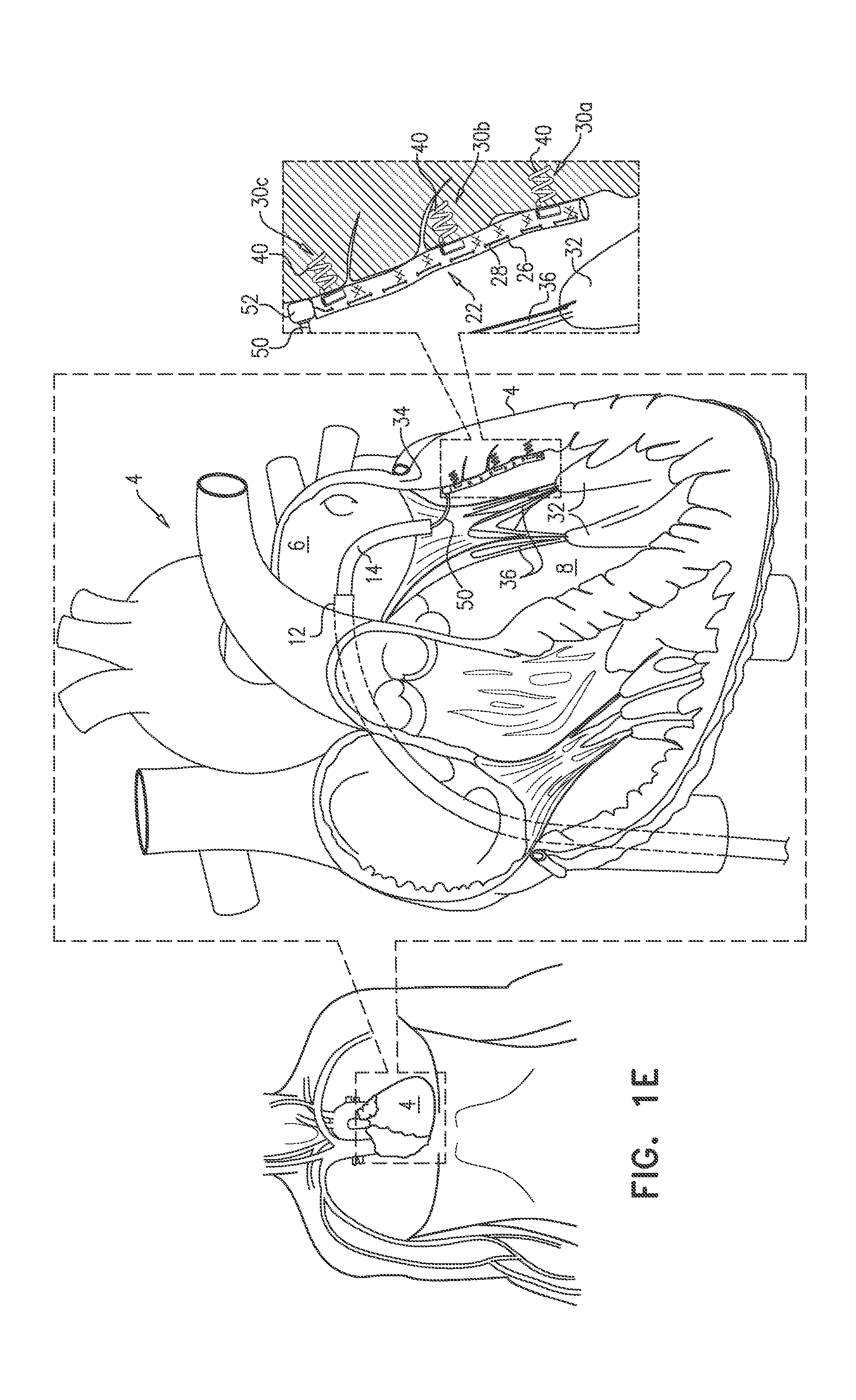
[0067] Reference is made to FIGS. 1A-F, which are schematic illustrations of an exemplary technique for treating a heart 4 of a subject. While examples herein are generally given or discussed with respect to treating or reshaping the left ventricle of a heart, the invention is not so limited and the principles, concepts, devices, apparatuses, systems, methods, etc. can be applied to treatment of other locations or regions of the heart or even other parts or organs of the body that may require reshaping.
[0068] A catheter 16 is advanced to a desired treatment location in the heart, e.g., a chamber of the heart. For example, catheter 16 can be advanced transfemorally into the left ventricle 8 via the mitral valve 10 (FIGS. 1A-C). Advancement to the treatment location is done using at least one catheter (e.g., a delivery catheter) and can be done using a plurality of catheters. Each catheter used can be steerable or configured to articulate or bend to help steer the system to the desired location.
[0069] The catheter or delivery catheter can be advanced to the desired treatment location in a number of different ways, for example, using transfemoral, transseptal, and/or transapical approaches. For some applications, advancement of catheter 16 into the left ventricle is achieved by (i) advancing a distal portion of a first catheter 12 into the left atrium 6 (FIG. 1A), (ii) advancing a distal portion of a second catheter 14 out of the distal portion of first catheter 12 and into left ventricle 8 via the mitral valve (FIG. 1B); and (iii) advancing a distal portion of catheter 16 (i.e., a third catheter) out of the distal portion of catheter 14 within the left ventricle (FIG. 1C). While three catheters are used in the example above, in some embodiments or applications, four catheters can be used. In some embodiments or applications, only two catheters or only one catheter (e.g., delivery catheter 16) can be used.
[0070] The distal portion of catheter 16 is positioned such that a distal end 17 (e.g., an open distal end) of the catheter faces a first tissue site, e.g., site 30a (FIG. 1C). For example, first tissue site 30a can be on a wall of a heart chamber, such as a ventricular wall of left ventricle 8 between a papillary muscle 32 and the mitral annulus 34, or between the apex or bottom/lower portion of the chamber and the annulus.
[0071] In some applications, implant 22 comprises an elongate flexible sleeve 26 that has a circumferential wall that circumscribes and defines a lumen along a longitudinal axis of the sleeve. In some applications, Implant 22 also comprises an elongate contraction member 28 that extends along the sleeve, e.g., extending through the lumen, being woven into the material of the sleeve, extending through loops on the outside, or otherwise extending along the outside or the inside of the sleeve.
[0072] A first part of the implant 22 and/or sleeve 26 is affixed or anchored to first tissue site 30a. This can be done using a variety of attachment means or fastening means, e.g., with anchors, sutures, clips, clamps, staples, adhesive, etc. In one embodiment or application, as shown, this is done using an anchor 40 that includes a coiled or helical tissue-engaging element 44 that can be screwed into tissue, but other types of anchors and tissue-engaging element configurations are also possible. Anchor 40 and anchoring techniques are shown and described in more detail with reference to FIG. 1D.
[0073] Subsequently, a second part of implant 22 and/or sleeve 26 that is proximal from the first part of the implant and/or sleeve is advanced out of open distal end 17 of catheter 16, the distal portion of catheter 16 is repositioned such that the open distal end faces a second tissue site 30b, and the second part of the implant and/or sleeve is affixed or anchored to the second tissue site. Again, this can be done using a variety of attachment means. In one embodiment or application, as shown, this is done using a second tissue anchor 40 (FIG. 1D). Second tissue site 30b can also be on the chamber wall, such as on the ventricular wall between papillary muscle 32 and annulus 34.
[0074] Optionally, second tissue site 30b can be closer to annulus 34 than is first site 30a. For some such applications, the repositioning of catheter 16 such that the open distal end faces second tissue site 30b can be performed by withdrawing catheter 16 into catheter 14, optionally without changing a degree of bending of the distal portion of catheter 16.
[0075] At least two parts of sleeve 26 can be anchored to corresponding tissue sites using corresponding tissue anchors or other attachment/fastening means. However, the above steps can be repeated with additional parts of the implant and/or sleeve and additional attachment means until the implant and/or sleeve is affixed/anchored to the treatment site as desired. In the example shown in the Figures, three parts of sleeve 26 are anchored to three respective tissue sites 30a, 30b, and 30c using three respective anchors 40 (FIG. 1E), but more or additional anchoring sites and anchors or other attachment/fastening means can be used. In one embodiment, 2-20 parts of the implant and/or sleeve and 2-20 attachment means or anchors can be used to affix/anchor the implant and/or sleeve to 2-20 tissue sites.
[0076] Each anchor 40 comprises a tissue-engaging element 44 and can comprise can comprise an anchor head 42. Tissue-engaging element 44 is shown as a coiled or helical portion that can be screwed or rotated into tissue, but other types of tissue-engaging elements and configurations are also possible. For some applications, the affixing or anchoring is performed by driving tissue-engaging element 44 through a portion of the implant 22, such as the circumferential wall of the corresponding part of sleeve 26 and into the corresponding tissue site. For some applications, a delivery channel 18 extends through catheter 16 and into the lumen of sleeve 26. Each anchor 40 can be delivered sequentially into the lumen of sleeve 26 via channel 18, and can be driven through the wall of the sleeve and into its tissue site using an anchor driver 46. A distal end of channel 18 can be disposed at the part of the sleeve being anchored. Between anchors, channel 18 can be partially withdrawn from the lumen of sleeve 26 such that the distal end of the channel becomes disposed at the next part of the sleeve to be anchored. The distal end of channel 18 can be used to press the part of the sleeve against the corresponding tissue site while the part of the sleeve is being anchored.
[0077] Sleeve 26 can be bent at the part of the sleeve being anchored, such that each anchor 40 can be driven in a straight line out of catheter 16 (and channel 18, if present) and through the circumferential wall of the sleeve.
[0078] Subsequently, to implantation of implant 22 (i.e., attachment/affixing/anchoring of the parts of implant 22 and/or sleeve 26 to the respective tissue sites), the implant 22 and/or sleeve 26 is contracted or reduced in length/distance from end to end to reshape the surrounding tissue and/or chamber of the heart by applying tension to the contraction member. In one embodiment, a distance between papillary muscle 32 (or lower portion of the chamber) and annulus 34 is reduced by contracting implant 22 and/or sleeve 26 along its longitudinal axis or length by applying tension to contraction member 28 (FIG. 1F).
[0079] For some subjects, if the papillary muscles and/or chordae tendineae restrain the leaflets of a native valve too much, this might prevent the leaflets from coming together and/or closing properly. For some subjects, the reduction in the distance between papillary muscle 32 and annulus 34 (e.g., by contracting the implant 22 and/or sleeve 26) may reduce mitral regurgitation by reducing tension and/or allowing the mitral leaflets to move further upstream and together during ventricular systole, thereby improving closure of mitral valve 10. Such subjects may include, for example, subjects with type IIIb mitral regurgitation and/or heart failure with reduced ejection fraction (HFrEF). Therefore, for some applications, the technique or methods of treatment include first identifying a subject as having one or more of these conditions.
[0080] The application of tension to contraction member 28 is generally achieved using an appropriate tool, such as adjustment tool 50. In FIGS. 1E-F, adjustment tool 50 is shown in contact with implant 22. For some applications, implant 22 can be implanted with adjustment tool 50 pre-coupled to implant 22. For some applications, adjustment tool 50 can be advanced to implant 22 (e.g., via at least one of catheters 12, 14 and 16) subsequent to implantation of the implant. For example, implant 22 can be implanted with a guide member attached, and adjustment tool 50 can be subsequently advanced to the implant along the guide member.
[0081] For some applications, implant 22, and the apparatus and techniques for its implantation, are implemented using technology the same as or similar to that described, mutatis mutandis, in one or more of the following publications, which are incorporated herein by reference:
[0082] U.S. Pat. No. 9,636,224 to Zipory et al.
[0083] U.S. Pat. No. 9,724,192 to Sheps et al.
[0084] US patent application publication 2015/0272734 to Sheps et al.
[0085] For some applications, implant 22 comprises an adjustment component 52 or other type of adjustment mechanism. For example, tension can be applied to contraction member 28 by actuating the adjustment component or other mechanism using tool 50. For example, adjustment component 52 can comprise a spool, drawstring(s), ratchet, tensioner, etc. Adjustment component 52 or other adjustment mechanism can comprise a lock, locking component, or other locking mechanism that locks a degree of tension of contraction member 28, e.g., by preventing further adjustment of the adjustment component or adjustment mechanism. For example, the lock, etc. may prevent rotation of a spool and/or hold the contraction member at a fixed tension, etc.
[0086] Optionally, for some applications, implant 22 may not comprise an actuatable adjustment mechanism as part of the implant, but instead can be contracted just by pulling on contraction member 28. For some such applications, implant 22 can comprise a locking component or mechanism (e.g., a lock, clamp, clip, etc.) that locks a degree of tension of contraction member 28, even in the absence of an actuatable adjustment mechanism.
[0087] For some applications, adjustment of implant 22 can be implemented using, alone or in combination, technology that is the same as or similar to that described, mutatis mutandis, in one or more of the following publications, which are incorporated herein by reference:
[0088] U.S. Pat. No. 9,636,224 to Zipory et al.
[0089] U.S. Pat. No. 9,724,192 to Sheps et al.
[0090] US patent application publication 2015/0272734 to Sheps et al.
[0091] Implant 22 can be implanted without capturing a chorda tendinea 36 between sleeve 26 and the ventricular wall. For some applications, this can be achieved by passing the distal portion of catheter 16 between two chordae tendineae when positioning the catheter at first tissue site 30a, and not withdrawing the catheter from between the two chordae tendineae until after all anchors 40 have been anchored. That is, the anchoring of all the parts of sleeve 26 can be performed while catheter 16 remains between the two chordae tendineae.
[0092] One or more of catheters (e.g., catheters 12, 14, and 16) can comprise one or more (e.g., two, three, four, etc.) pull-wires, and the distal end of the catheter can be deflectable (e.g., "steerable") by tensioning at least one of or one or more of the pull-wires. For example, within left atrium 6, the distal portion of catheter 14 can be deflected with respect to the distal portion of catheter 12. Further, within left ventricle 8, the distal portion of catheter 16 can be deflected with respect to the distal portion of catheter 14. For some applications, the distal portion of catheter 12 can be deflected with respect to a portion of catheter 12 that is proximal (e g , immediately proximal) to its distal portion, in order to facilitate transseptal access to left atrium 6.
[0093] For some applications, the catheters are configured such that the operator can rotationally lock the distal portion of catheter 12 with respect to catheter 14, and the deflecting of the distal portion of catheter 14 can be performed while the distal portion of the first catheter remains rotationally locked to the second catheter.
[0094] For some applications, the catheters of the present application, and their steering and locking, may be implemented using, alone or in combination, technology the same as or similar to that described, mutatis mutandis, in one or more of the following publications, which are incorporated herein by reference:
[0095] U.S. Pat. No. 9,636,224 to Zipory et al.
[0096] U.S. Pat. No. 9,724,192 to Sheps et al.
[0097] US patent application publication 2015/0272734 to Sheps et al.
[0098] For some applications, the operator can rotationally lock the distal portion of catheter 14 with respect to catheter 16, and the deflecting of the distal portion of catheter 16 can be performed while the distal portion of the first catheter remains rotationally locked to the second catheter. Optionally, catheter 16 can be rotatable with respect to (e.g., within) catheter 14, and the operator can rotate catheter 16 with respect to catheter 14, e.g., while the distal end of catheter 16 is disposed in left ventricle 8, for example, in order to position the open distal end of catheter 16 at the appropriate tissue site.
[0099] Reference is made to FIGS. 2A-B, 3, 4, 5, 6, and 7, which are schematic illustrations of an exemplary implant 122, and exemplary techniques for implantation thereof, in accordance with some applications of the invention.
[0100] Implant 122 comprises an elongate flexible sleeve 126 that has a circumferential wall that circumscribes and defines a lumen along a longitudinal axis of the sleeve. Implant 122 further comprises a contraction member 128 that can be elongate and extend along the sleeve. Sleeve 126 can be the same as or similar to sleeve 26, mutatis mutandis.
[0101] Sleeve 126 has a first-end portion 121, a second-end portion 125, and a mid-portion 123 longitudinally therebetween. The lumen of sleeve 126 can extend between first-end portion 121 and second-end portion 125.
[0102] Contraction member 128 can take a variety of shapes and forms. For example, contraction member 128 can be the same as or similar to contraction member 28 described above. In one embodiment or application, contraction member 128 defines a first region 130 and a second region 132. For some applications, first region 130 can extend along sleeve 126 from first-end portion 121 to second-end portion 125, and second region 132 can extend, outside of the sleeve, back from the second-end portion to the first-end portion.
[0103] For some applications, and as shown, first region 130 can extend along sleeve 126 by forming part of the circumferential wall and/or weaving in and out along the sleeve (i.e., along the circumferential wall). Alternatively, first region 130 can extend along sleeve 126 by being disposed within the lumen or extending through the lumen.
[0104] Implant 122 can comprise a housing 148 that is coupled to first-end portion 121 of sleeve 126, and/or to the contraction member 128. Housing 148 can define an opening or eyelet 149 through which contraction member 128 can extend, such that pulling of the contraction member (e.g., region 132 thereof) through the eyelet can draw second-end portion 125 toward first-end portion 121 by reducing a length of second region 132.
[0105] Implant 122 can further comprise a lock, locking device, and/or locking mechanism 151, e.g., coupled to housing 148. Lock or locking device 151 can have an unlocked state in which contraction member 128 is pullable through eyelet 149, and a locked state in which the locking mechanism inhibits pulling of the contraction member through the eyelet.
[0106] First region 130 can include a first end 131 of contraction member 128, and second region 132 can include a second end of the contraction member (not visible). Optionally, first end 131 can be attached to the first-end portion of the sleeve, e.g., as shown.
[0107] For some applications, implant 122 can comprise an adjustment component 152, or other adjustment mechanism, which can be coupled to second region 132 of contraction member 128, e.g., as shown in FIG. 2A. Adjustment component 152 can be configured such that actuation of adjustment component 152 can pull contraction member 128 (e.g., second region 132 thereof) through eyelet 149 and into housing 148. For some such applications, adjustment component 152 can be disposed within housing 148 and/or can be a component of housing 148. For such applications, lock or locking component 151, in its locked state, can inhibit actuation of the adjustment component or other adjustment mechanism. For some applications, adjustment component 152 and locking component 151 can be implemented using adjustment components or mechanisms and locking components or mechanisms described, mutatis mutandis, in one or more of the following publications, which are incorporated herein by reference:
[0108] U.S. Pat. No. 9,636,224 to Zipory et al.
[0109] U.S. Pat. No. 9,724,192 to Sheps et al.
[0110] US patent application publication 2015/0272734 to Sheps et al.
[0111] For some applications, adjustment component 152 comprises a spool, and can be configured such that rotation of the spool pulls second region 132 of contraction member 128 through eyelet 149 and into housing 148 where the spooled-in contraction member is stored on the spool.
[0112] FIG. 2B shows an optional embodiment of implant 122--implant 122a. Implant 122a can be identical or similar to implant 122, except where noted. For example, instead of housing 148, implant 122a comprises a housing 148a, which defines an opening or eyelet 149a. Implant 122a does not comprise an adjustment mechanism, and housing 148 does not collect contraction member 128 as it is pulled through eyelet 149a. Rather, contraction member 128 is pulled proximally from a site that is proximal from implant 122a, such that the contraction member is pulled through eyelet 149a and out of a proximal side of housing 148. Instead of locking component 151, implant 122a comprises a locking component 151a, which can engage contraction member 128 directly, rather than inhibiting movement of an adjustment mechanism. FIGS. 3-7 show implant 122 being used as an example, but it is to be noted that implant 122a or another implant can be used instead, mutatis mutandis.
[0113] Implant 122 is delivered via a delivery tube/catheter, such as delivery catheter 116. FIG. 3 shows implant 122 in its delivery state, within catheter 116. In the delivery state, region 132 of contraction member 128 can be disposed outside and alongside sleeve 126, and therefore between the sleeve and the wall of catheter 116. For some applications, a deployment tool 160 is used to facilitate movement of implant 122 out of catheter 116, e.g., by providing a reference force as catheter 116 is withdrawn from the implant.
[0114] Implant 122 can be implanted in the left ventricle 8 of the heart or in another chamber of the heart, e.g., the right ventricle. Implant 122 can be delivered to the chamber of the heart in a variety of ways, e.g., transfemorally, transapically, and/or transseptally. In one embodiment or application, implant 122 is delivered to the left ventricle 8 via the interatrial septum, e.g., as shown in FIG. 4. In one embodiment or application, implant 122 is delivered to the left ventricle 8 via the interventricular septum, e.g., as shown in FIG. 5. As another option, implant 122 can be delivered by a retrograde approach via the aortic valve (not shown), or transapically (not shown). While examples are given with respect to the left ventricle, the implant, delivery systems, methods, etc. described herein can be adapted for delivery to another chamber of the heart (e.g., left atrium, right atrium, and/or right ventricle) for treatment and/or to modify the shape of the chamber.
[0115] Within ventricle 8 (or within another chamber), implant 122 and/or sleeve 126 is affixed or anchored in a curved path along the ventricular wall (or other chamber wall) using an attachment means or anchor such that a direct distance between end portions 121 and 125 is shorter than a distance along the sleeve between the end portions. Sleeve 126 can be affixed/anchored using techniques described hereinabove for sleeve 26, mutatis mutandis. For example, anchors 40 can be sequentially delivered into the lumen of the sleeve, and can be used to progressively anchor respective sleeve-sites along the sleeve. That is, an exemplary method for implanting the sleeve comprises advancing progressively proximal sleeve-sites of the sleeve out of an open distal end of catheter 116, and anchoring (or otherwise fastening/attaching/affixing) the sleeve-sites to respective tissue sites. The plurality of sleeve-sites can include a first sleeve-site within first-end portion 121 and a second sleeve-site within second-end portion 125. As described for sleeve 26, mutatis mutandis, sleeve 126 can be implanted without capturing a chorda tendinea of the heart between the sleeve and the ventricular wall.
[0116] Subsequent to the anchoring (or fastening/attachment/affixing), the ventricular wall (or other chamber wall) is reshaped by cinching or contracting the implant by tensioning the contraction member. For some applications, this is done by reducing the direct distance between the first-end portion and the second-end portion by pulling on the elongate contraction member such that a length of the elongate contraction member that is disposed between the first-end portion and the second-end portion becomes reduced (e.g., reducing a radius of curvature of the curved path of the sleeve). As described hereinabove, this can be achieved with or without an adjustment component or adjustment mechanism that is part of the implant. It is believed that such reshaping of the ventricular wall may reduce mitral regurgitation and/or improve ventricular ejection fraction (and reshaping of other chambers/chamber walls may have similar advantages in other chambers).
[0117] As described hereinabove for implant 22, mutatis mutandis, implant 122 can be implanted with and adjustment tool attached thereto, or an adjustment tool can be advanced to the implant subsequent to implantation of the implant.
[0118] Subsequent to the adjustment, a lock, locking component 151 or other locking mechanism can be transitioned into its locked state, e.g., by releasing an element (not shown) that had been retaining the locking mechanism in its unlocked state.
[0119] For some applications, one of the end portions can be anchored to a portion of a wall of the chamber, e.g., an outer wall (i.e., non-septum wall), such as a ventricular wall, and the other end portion can be anchored to an interchamber (e.g., interventricular) septum of the heart, e.g., as shown in FIGS. 4 and 5. For some applications, one of the end portions can be anchored to a posterior papillary muscle, and the other end portion can be anchored to an anterior papillary muscle, e.g., as shown in FIGS. 6 and 7. For some applications, mid-portion 123 can be anchored to apex 9 of the heart (i.e., the apical part of ventricle 8), e.g., as shown in FIGS. 4, 5, and 6. For some applications, mid-portion 123 can be anchored higher in the ventricle, such as circumferentially around a lateral part of the ventricular wall, e.g., at the level of the papillary muscles, or even higher, such as shown in FIG. 7, which can allow for cinching the papillary muscles closer to each other. Similar arrangements to the foregoing may be used in other chambers, mutatis mutandis.
[0120] It is to be noted that implant 122 can be arranged inversely, with housing 148, locking mechanism 151 and/or adjustment mechanism 152 disposed at second end portion 125. Similarly, implant 122 can be implanted the other way around to that shown or described, i.e., with the position of end portions 121 and 125 reversed.
[0121] For some applications, first region 130 can be slidably coupled to sleeve 126, such that the pulling of contraction member 128 through eyelet 149 slides the first region through the sleeve. For such applications, contraction member 128 can be slidably coupled to second-end portion 125 of sleeve 126, and the pulling of the contraction member through opening or eyelet 149 slides the contraction member with respect to the first portion of the sleeve. For example, and as shown, contraction member 128 can exit second-end portion 125 at a second opening or eyelet 134, such that eyelet 134 delimits first region 130 of the contraction member from second region 132 of the contraction member. For such applications, the pulling of contraction member 128 through eyelet 149 can compress sleeve 126 longitudinally. Therefore, for such applications, in addition to reducing the direct distance between end portions 121 and 125, the pulling of contraction member 128 through eyelet 149 can also contract the tissue along the curved path in which sleeve 126 is anchored.
[0122] The above systems, platforms, devices, features, aspects, methods, etc. have generally been described with respect to particular embodiments; however, the principles described can be applied to other types of systems, platforms, devices, features, aspects, methods, etc. Further, features described in one embodiment above, including embodiments described in the Summary section, can generally be combined with features described in other embodiments herein. The scope of the present invention includes both combinations and subcombinations of the various features described hereinabove, as well as variations and modifications thereof that are not in the prior art, which would occur to persons skilled in the art upon reading the foregoing description. Methods described separately may be combined. In addition, where methods and steps described above indicate certain events occurring in certain order, the ordering of certain steps can be modified and that such modifications are in accordance with the variations of the invention. Additionally, certain of the steps may be performed concurrently in a parallel process when possible, as well as performed sequentially as described above. Many modifications can be made to adapt a particular situation or device to the teachings of the invention without departing from the essential scope thereof. Therefore, to the extent there are variations of the invention, which are within the spirit of the disclosure or equivalent to the inventions found in the claims, it is the intent that this patent will cover those variations as well.
* * * * *
D00000
D00001
D00002
D00003
D00004
D00005
D00006
D00007
D00008
D00009
D00010
D00011
D00012

XML
uspto.report is an independent third-party trademark research tool that is not affiliated, endorsed, or sponsored by the United States Patent and Trademark Office (USPTO) or any other governmental organization. The information provided by uspto.report is based on publicly available data at the time of writing and is intended for informational purposes only.
While we strive to provide accurate and up-to-date information, we do not guarantee the accuracy, completeness, reliability, or suitability of the information displayed on this site. The use of this site is at your own risk. Any reliance you place on such information is therefore strictly at your own risk.
All official trademark data, including owner information, should be verified by visiting the official USPTO website at www.uspto.gov. This site is not intended to replace professional legal advice and should not be used as a substitute for consulting with a legal professional who is knowledgeable about trademark law.