Method And Measuring System For Continuously Determining The Intra-arterial Blood Pressure
Fortin; Jurgen ; et al.
U.S. patent application number 16/078743 was filed with the patent office on 2019-05-23 for method and measuring system for continuously determining the intra-arterial blood pressure. The applicant listed for this patent is CNSYSTEMS MEDIZINTECHNIK AG. Invention is credited to Andrea Fortin, Jurgen Fortin, Klaus Popp.
| Application Number | 20190150765 16/078743 |
| Document ID | / |
| Family ID | 55587972 |
| Filed Date | 2019-05-23 |


| United States Patent Application | 20190150765 |
| Kind Code | A1 |
| Fortin; Jurgen ; et al. | May 23, 2019 |
METHOD AND MEASURING SYSTEM FOR CONTINUOUSLY DETERMINING THE INTRA-ARTERIAL BLOOD PRESSURE
Abstract
The invention describes a measuring system for the continuous non-invasive determination of blood pressure at one or more fingers. The fingers chosen for measurement and the adjacent parts of the palm rest on a supporting surface of a housing, which has the shape of a computer mouse. Inside the housing of the "CNAP Mouse", i.e. underneath the supporting surface for the hand, the pressure generating system is located. The finger sensors are mounted on the supporting surface for the hand. The forearm and the back of the hand are left free and may be used to place intra-venous or intra-arterial access elements. Since the hand will rest on the supporting surface motion artefacts are largely avoided. Tilting or turning of the sensors is hardly possible since the fit of the sensors and thus the coupling of light and pressure are optimized.
| Inventors: | Fortin; Jurgen; (Graz, AT) ; Fortin; Andrea; (Graz, AT) ; Popp; Klaus; (Windischgarsten, AT) | ||||||||||
| Applicant: |
|
||||||||||
|---|---|---|---|---|---|---|---|---|---|---|---|
| Family ID: | 55587972 | ||||||||||
| Appl. No.: | 16/078743 | ||||||||||
| Filed: | February 22, 2016 | ||||||||||
| PCT Filed: | February 22, 2016 | ||||||||||
| PCT NO: | PCT/AT2016/050035 | ||||||||||
| 371 Date: | November 7, 2018 |
| Current U.S. Class: | 1/1 |
| Current CPC Class: | A61B 2560/0425 20130101; A61B 5/02255 20130101; A61B 5/02241 20130101; A61B 5/6897 20130101; A61B 5/6826 20130101; A61B 5/70 20130101; A61B 5/0235 20130101; A61B 2562/04 20130101 |
| International Class: | A61B 5/0225 20060101 A61B005/0225; A61B 5/022 20060101 A61B005/022; A61B 5/00 20060101 A61B005/00 |
Claims
1.-16. (canceled)
17. A measuring system for the continuous determination of intra-arterial blood pressure at one or more fingers of a hand, with at least one finger sensor, with a plethysmographic system with: at least one light source, preferably LED with one or more wavelengths, and at least one light detector; and with at least one inflatable cuff, and with a pressure generating system with; at least one valve, controlled in real time by the plethysmographic system, for generating pressure in the cuff, which pressure essentially corresponds to the intra-arterial blood pressure in the finger, wherein the measuring system has a housing with a surface which serves as a supporting surface for the at least one finger and adjacent areas of the palm.
18. The measuring system according to claim 17, wherein the housing of the measuring system has essentially the dimensions and shape of a computer mouse, where the at least one finger sensor is projecting from the supporting surface for the hand.
19. The measuring system according to claim 17, wherein the pressure generating system with the at least one controlled valve is located in the housing underneath the supporting surface for the hand.
20. The measuring system according to claim 17, wherein on the top surface of the housing there is provided a receiving slot, which partitions the supporting surface essentially mirror-symmetrically into two partial surfaces and contains elements for connecting the plethysmo-graphic system to the at least one finger sensor, which preferably is configured as a double finger sensor.
21. The measuring system according to claim 20, wherein two outer elements are disposed in the receiving slot of the housing so as to be slideable in the direction of a central element, on which elements the part of the finger sensor holding the inflatable cuffs is detachably mounted.
22. The measuring system according to claim 21, wherein the outer, slideable elements contain the light sources, preferably LEDs, while the central element contains the light detectors.
23. The measuring system according to claim 17, wherein a control system, preferably a microcontroller is disposed in the housing underneath the supporting surface for the hand.
24. The measuring system according to claim 17, wherein a pump and an air reservoir are disposed in the housing underneath the supporting surface for the hand.
25. The measuring system according to claim 17, wherein the housing of the measuring system is made air-tight underneath the supporting surface for the hand, and acts as an air reservoir.
26. The measuring system according to claim 17, wherein a battery or a power pack and elements for the wireless transmission of signals are disposed in the housing underneath the supporting surface for the hand.
27. A method for the continuous determination of intra-arterial blood pressure at one or more fingers of a hand by means of at least one finger sensor, which is provided with a plethysmographic system with; at least one light source, preferably LED, and at least one light detector and with at least one inflatable cuff, where the pressure in the inflatable cuff of the finger sensor is controlled by the plethysmographic system via a pressure generating system, wherein the at least one finger which is used for measurement, is introduced into the inflatable cuff and together with the adjacent area of the palm rests on a supporting surface of the housing to keep the hand relaxed, the plethysmo-graphic system and the pressure generating system being contained in said housing.
28. The method according to claim 27, wherein the basic pressure needed for the pressure generating system is supplied via a tube system from a pressure source external to the housing.
29. The method according to claim 27, wherein the basic pressure needed for the pressure generating system is generated inside the housing by means of a built-in pump.
30. The method according to claim 27, wherein the control signals for the pressure generating system are produced outside the housing and are fed in via a cable.
31. The method according to claim 27, wherein the control signals for the pressure generating system are computed inside the housing by means of a control system.
32. The method according to claim 27, wherein the at least one finger sensor is exchangeably mounted on the supporting surface for the hand.
Description
CROSS REFERENCE TO RELATED APPLICATIONS
[0001] The present application is a U.S. National Phase Application pursuant to 35 U.S.C. .sctn. 371 of International Application No. PCT/AT2016/050035 filed Feb. 22, 2016. The entire disclosure content of this application is herewith incorporated by reference into the present application.
BACKGROUND
[0002] The invention relates to a method and a measuring system for continuously determining the intra-arterial blood pressure at one or more fingers of a hand by means of a finger sensor. The sensor comprises a plethysmographic system with at least one light source, at least one light receiver or light detector, and at least one inflatable cuff. Further there is provided a pressure generating system with at least one valve, which is controlled in real time by the plethysmographic system for generating pressure in the cuff, the pressure essentially corresponding to the intra-arterial blood pressure in the finger.
[0003] Continuous non-invasive measurement of blood pressure presents even today a serious challenge to measuring technology. The so-called "Vascular Unloading Technique" is beginning to dominate the market. This technique is based on a publication by Penaz (Digest of the 10.sup.th International Conference on Medical and Biological Engineering, 1973 Dresden) and has been improved by diverse enhancements.
[0004] The Vascular Unloading Technique begins with shining light through a finger, thus determining the pulsatile (pulse-shaped) blood flow in the finger. This method is called photo-plethysmography (PPG) and is usually implemented with the use of one or more light-emitting diodes (LEDs) working at one or more wavelengths, and one or more light-sensitive receiving diodes (photo diodes).
[0005] A control system keeps the registered flow and thus the resulting PPG signal (volume signal v(t)) constant by applying counter pressure in a cuff (cuff pressure p.sub.c(t)) around the finger. This counter pressure p.sub.c(t) is generated via a fast valve or valve system fed by a pump. The valve or valve system is controlled by the control unit, which preferably is realized as a microcomputer. The essential input signal is the PPG signal v(t), in more recent control systems the cuff pressure p.sub.c(t) is used as an additional input variable. The pressure p.sub.c(t) necessary to keep the flow or rather the PPG signal v(t) constant thus corresponds to the intra-arterial blood pressure p.sub.a(t).
[0006] In order to fulfill the real-time condition it is necessary that the cuff pressure p.sub.c(t) can be varied at least as fast as the intra-arterial blood pressure p.sub.a(t) changes. For complete fulfillment of this control condition the cuff pressure p.sub.c(t) must be able to mimic the intra-arterial pressure p.sub.a(t) in the time domain as well as in the frequency domain. The upper frequency limit of p.sub.a(t) and thus the highest rate of change of the pressure lies upwards of at least 20 Hz, presenting a serious challenge for the pressure system. As a consequence pressure generation via a valve or valve system must be located in the immediate vicinity of the cuff. If long air tubes are used the frequency limit condition cannot be met due to the low-pass characteristic of the tubes. In all known devices commercially available or described in publications, the valve or valve system or pressure generating system is therefore located on the distal forearm next to the wrist, either on the upper side or underside of the arm.
[0007] Placing the pressure generating system on the distal forearm next to the wrist has serious disadvantages: this site is often chosen for intravenous access points and intra-arterial access should also be possible at the distal end of radius in cases of emergency. These access points would be blocked by the pressure generating system and its fastening elements. The system might also slip or tilt during operation. This might have an adverse effect on the positioning of the sensors. Positioning of the sensors would moreover be improved if the finger to be measured or the corresponding hand could be held in a state of rest.
[0008] A large number of publications concerning the Vascular Unloading Technique are known: U.S. Pat. No. 4,406,289 (Wesseling et al.) describes a mechanical valve which generates the counter pressure in the finger cuff with desired accuracy if fed by a linear pump. The valve is placed in a housing at the distal forearm and supplies pressure p.sub.c(t) to the finger cuff via a short tube.
[0009] U.S. Pat. No. 4,524,777 (Kisioka et al.) describes a pressure generating system for the Vascular Unloading Technique. A constant cuff pressure P.sub.c is first generated by a linear pump on which pressure fluctuations .DELTA.p.sub.c(t) are superimposed, which are supplied by a "shaker" or "driving actuator" connected in parallel.
[0010] U.S. Pat. No. 4,726,382 (Boehmer et al.) describes a finger cuff for the Vascular Unloading Technique, which has tube fittings for supplying the cuff pressure p.sub.c(t). The length of the tubes is sufficient to reach the pressure generation system (not shown) placed on the distal forearm.
[0011] WO 2000/059369 (Fortin et al.) also describes a pressure generating system for the Vascular Unloading Technique. The valve system consists of a separate inlet and a separate outlet valve. While U.S. Pat. Nos. 4,406,289 and 4,524,777 require a relatively linear proportional pump, this system permits the use of simple, less costly pumps, since noxious harmonics are eliminated due to the arrangement of the valves. Furthermore the energy required for the simple pump is substantially reduced due to the valve principle.
[0012] WO 2004/086963 (Skrabal et al.) describes a system for the Vascular Unloading Technique, in which blood pressure can be continuously measured in one finger, while the adjacent finger ("Watch Dog") is used for quality control. After a certain time the system automatically exchanges the "measurement finger" and the "supervisor finger".
[0013] WO 2005/037097 (Fortin et al.) describes a control system for the Vascular Unloading Technique, in which a plurality of nested control loops provide for high frequency pressure variation and long time stability of accuracy.
[0014] WO 2010/050798 (Guelen et al.) essentially describes a pressure generation system attached to the distal forearm ("Frontend") with only one valve that can be connected to a finger cuff for the Vascular Unloading Technique.
[0015] WO 2011/045138 (Langewouters et al.) describes a pressure generation system for the Vascular Unloading Technique, where--similar to WO 2000/059369--energy consumption of the pump is reduced and harmonics are eliminated.
[0016] WO 2011/051819 (Fortin et al.) describes a novel kind of Vascular Unloading Technique entirely implemented by digital electronics, with improved stability and further miniaturization.
[0017] WO 2011/051822 (Fortin et al.) describes a method for the Vascular Unloading Technique, in which the measured signals v(t) and p.sub.c(t) are processed such that long term stability is improved and further hemodynamic parameters can be obtained. In particular, a method for eliminating vasomotoric fluctuations of the finger arteries and a method for determining the cardiac output are described.
[0018] WO 2012/032413 (Huber et al.) describes a novel kind of finger sensors with a disposable part.
SUMMARY
[0019] It is the object of the present invention, given a measuring system for continuous non-invasive determination of intra-arterial blood pressure as initially described, to propose improvements enhancing the patient's wearing comfort and to avoid tiring hand positions during lengthy measurement periods.
[0020] According to the invention this object is achieved by providing that the measuring system has a housing with a surface which may serve as a supporting surface for the at least one finger and adjacent parts of the palm. Preferably the housing of the measuring system should essentially have the dimensions and the outer shape of a computer mouse, with the at least one finger sensor projecting from the supporting surface for the hand.
[0021] A measuring method according to the invention using a plethysmographic system and a pressure generating system controlled by the plethysmographic system, is characterized in that the finger or fingers chosen for measurement are introduced into the inflatable cuff and, to ease tension in the hand, are placed on a supporting surface of a housing together with adjacent parts of the palm, which housing contains the pressure generating system.
[0022] The present invention combines the finger sensor, i.e. the finger cuff and its light generating system, and the pressure generating system, thereby avoiding the disadvantages cited above. The fingers chosen for measurement and the respective hand rest on a supporting surface beneath which the pressure generating system is located. One or more finger sensors, i.e. the finger cuffs including the PPG system, are disposed on the supporting surface for the hand. The forearm and the back of the hand are free and thus available for intra-venous or intra-arterial access points. Since both the fingers used for measurement and the hand rest on the supporting surface, artefacts due to motion are reduced. Turning or tilting of the sensors is hardly possible as the positioning of the sensors and thus the coupling of light and pressure are optimized.
[0023] Since the hand will rest on the supporting surface like on a computer mouse, the system is called CNAP Mouse (Continuous Non-invasive Arterial Pressure). The body or the housing of the "mouse" contains at least the pressure generating system for the Vascular Unloading Technique. The "ears" of the CNAP mouse are represented by the usually two finger sensors (cuffs including the PPG system). Two finger sensors are used to permit a longer period of measurement by interchanging the role of the fingers; while one finger is used for measuring continuous blood pressure, the other finger is at rest. The CNAP mouse of course also works with only one "ear", i.e. with only one finger sensor.
[0024] The invention will now be described in more detail, with reference to schematically presented exemplary embodiments.
BRIEF DESCRIPTION OF THE FIGURES
[0025] FIG. 1 shows a state-of-the-art measuring system, where the pressure generating system is placed at the distal end of the forearm;
[0026] FIG. 2 shows the measuring system according to the invention in the shape of a computer mouse (CNAP mouse) in a three-dimensional view;
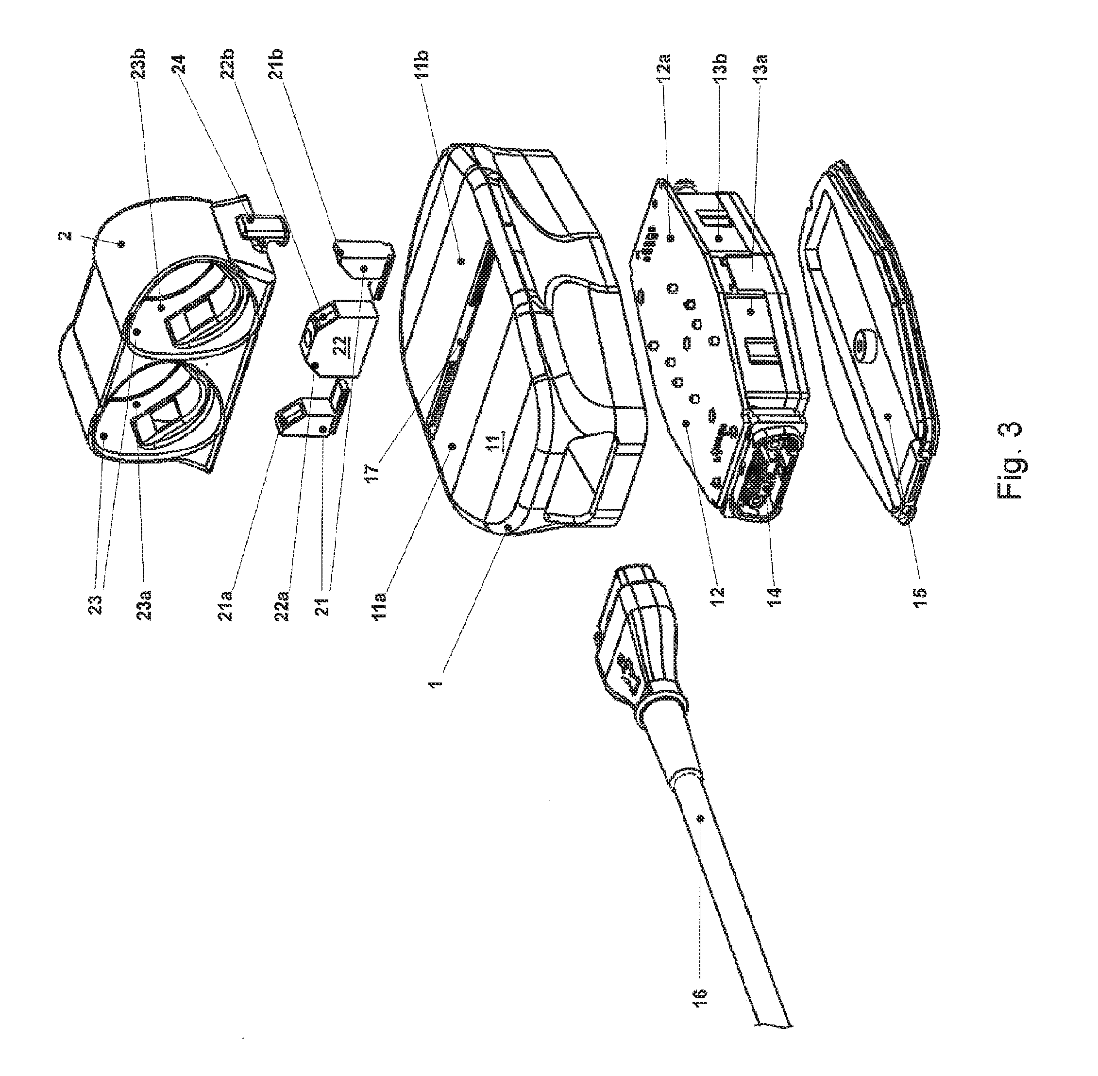
[0027] FIG. 3 shows the measuring system of FIG. 2 in an exploded view;
[0028] FIG. 4 shows the measuring system of FIG. 2 with the cuff part removed and the PPG elements visible;
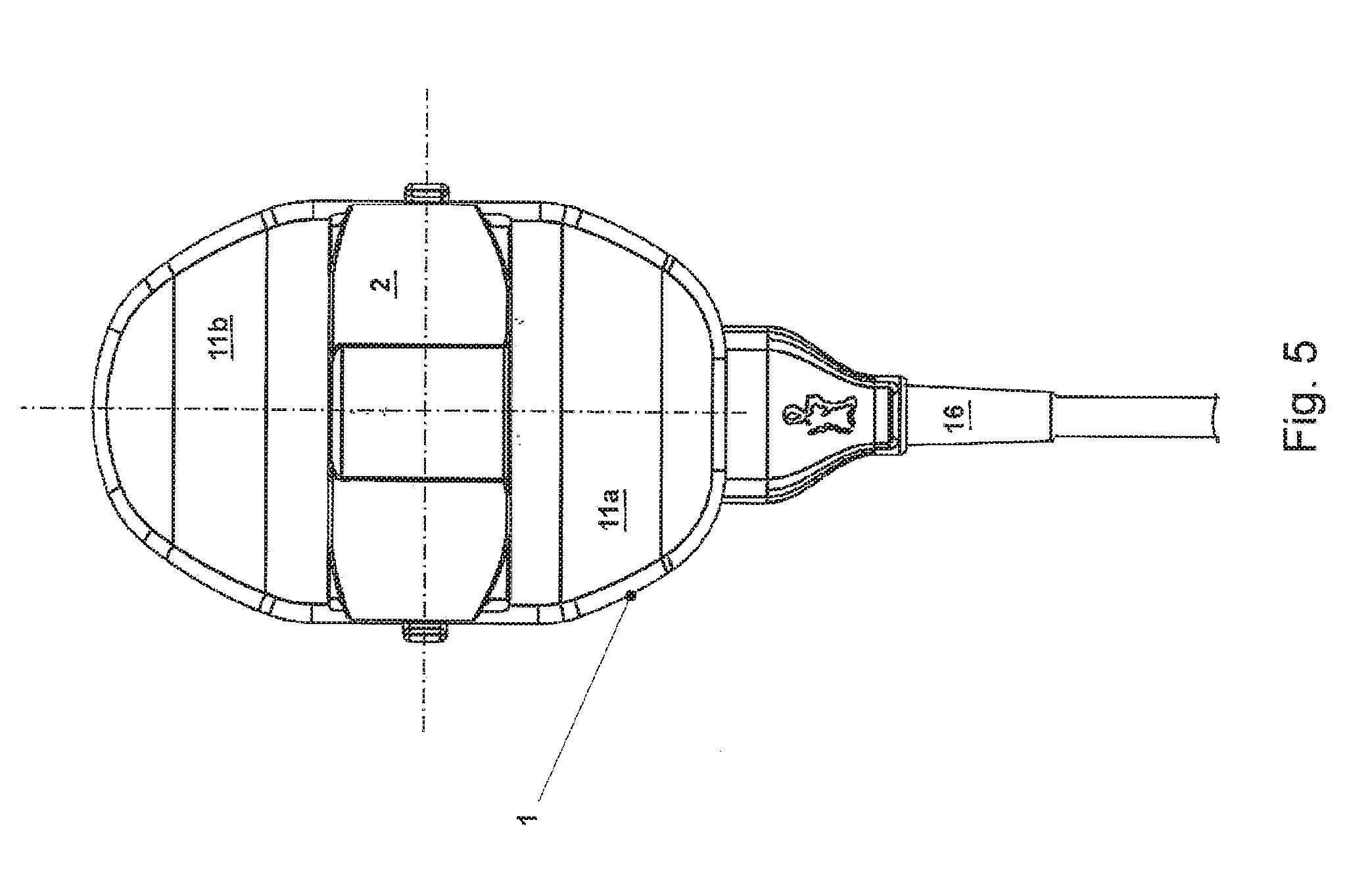
[0029] FIG. 5 shows the symmetrical design of the measuring system of FIG. 2 in a top view;
[0030] FIG. 6 shows all possible ways of applying the measuring system to the right or left hand of a patient; and
[0031] FIG. 7 shows a variant of the measuring system according to the invention in an exploded view.
DETAILED DESCRIPTION
[0032] The invention describes a measuring system for the continuous non-invasive determination of blood pressure. The combination of pressure generating system and finger sensors comprising cuff and light system--the photoplethysmographic system--is presented in detail.
[0033] In principle the Vascular Unloading Technique mimics the intra-arterial pressure in the finger cuff in real time. This is done by means of a control system which requires as input signal at least the light signal v(t) of the PPG system. More recent control systems, such as described in publications WO 2000/059369, WO 2005/037097, WO 2011/0511819 or WO 2011/051822, also use the cuff pressure p.sub.c(t) as an input variable.
[0034] The pressures obey the following equation, which arises when the air-filled cuff is applied:
p.sub.c(t)=p.sub.a(t)-p.sub.t(t) (1)
[0035] where p.sub.t(t) is the socalled "transmural pressure", i.e. the pressure difference between cuff pressure p.sub.c(t) and intra-arterial blood pressure p.sub.a(t).
[0036] The transmural pressure p.sub.t(t) acts on the diameter of the artery, which diameter can indirectly be determined from the PPG signal or volume signal v(t). As has been described above, the control system will adapt the cuff pressure p.sub.c(t) in real time such that v(t) will be kept constant, i.e. that .DELTA.v(t)=0. If this condition .DELTA.v(t)=0 is fulfilled, the transmural pressure p.sub.t(t)=0, and therefore one has
p.sub.c(t)=p.sub.a(t)-0 (2)
[0037] In order to fulfil this real-time condition, the measuring system must be able to follow the changes in intra-arterial blood pressure p.sub.a(t). Interpreting the control condition in the frequency domain the measuring system must be able to mimic pressure changes which transcend the upper limit frequency of intra-arterial blood pressure. This upper limit freqency of intra-arterial blood pressure p.sub.a(t) lies approximately at 20 Hz.
[0038] All the methods and devices described require that the cuff pressure p.sub.c(t) must be available over the total relevant frequency range with an upper limit frequency of at least 20 Hz, a requirement which presents a challenge to the pressure generating system and its valves or valve system. It is therefore important that the pressure generating system and its valve or valve system be situated in the immediate vicinity of the finger cuff. Depending on the rigidity of the connecting tube, the maximum distance will be 30 to 50 cm.
[0039] FIG. 1 shows how the pressure system 101 is connected to the finger sensor 102 in a state-of-the-art measuring system. The finger sensor 102 shown is designed as a double finger sensor for index and middle finger 100 of the right hand, permitting longer duration of measurement. The finger sensor 102 is supplied with pressure and electric energy via a double tube system 103. The pressure system 101 is attached to the distal end of the forearm by means of a fastening element 104 and is supplied via a cable 105 with electric energy and with basic pressure.
[0040] FIG. 2 shows the measuring system according to the invention, the assembled CNAP mouse. On the body or on the housing 1 of the CNAP mouse there is provided a relatively large supporting surface 11 upon which the hand may rest during the measuring operation. The finger sensors 2 are attached to the housing 1. In the example there is shown a double finger sensor, with which each finger may be measured alternatingly. The double sensor has two light sources (LEDs) 21a, 21b and at least two light sensors 22a, 22b (partly visible). The two inflatable cuffs 23a and 23b are disposed on the interior areas 23 of the finger sensors 2. The part of the finger sensor 2 which carries the inflatable cuffs 23a, 23b is removable and may be exchanged, and is attached to a locking element on the housing 1 by means of snap-on element 24.
[0041] FIG. 3 shows an exploded view of the CNAP mouse. First it is shown how the pressure generating system 12 is integrated into the body or the housing 1 of the mouse underneath the supporting surface 11 for the hand. In this case the pressure generating system 12 consists of an electronic circuit board 12a, which carries one or more valves 13a, 13b as well as the elements of the valve control electronics. Preferably, a connector 14 is also provided on the board 12a. The pressure generating system 12 is placed in the housing 1 and secured by a cover 15 on the bottom of the housing 1. A cable 16 supplies the pressure generating system 12 with basic pressure, electric energy and the signals emitted by the control system for the Vascular Unloading Technique.
[0042] On the top face of the housing 1 there are provided fittings for one or more finger sensors. On the one hand these must have electric connectors for the PPG signal, on the other hand there must be provided pressure fittings for supplying pressure to the one or more cuffs. In the variant shown, which presents the double finger system as described above, this is achieved as follows: a receiving slot 17 partitions the top of the body of the mouse 1, which is also the supporting surface 11, into two partial surfaces 11a and 11b. Into this slot two outer slideable elements 21 and a central element 22 are inserted. The slideable elements 21 contain the two LEDs 21a and 21b necessary for generating the PPG signal. The outer elements are movable in order to accommodate various sizes of the finger sensor. The element 22 sits in the middle of the slot and is not movable. It contains the two light detectors 22a and 22b.
[0043] Onto this body or housing 1 of the mouse carrying the elements 21, 22 for the PPG signal as shown, the detachable part of the finger sensor 2 may be mounted. The finger sensors may have diverse sizes or diameters. The optimum fit of the sensors may thus be adapted to the actual finger size. The sensors have an air-inflatable cuff 23a, 23b whose pressure can be controlled by the pressure generating system 12 with the required accuracy. For this purpose fitting elements are provided, which are integrated in the element 22 (not explicitly shown). Furthermore the PPG system must be integrated into the sensors. In the case shown this is realized by the double finger sensor 2 already known. The double finger sensor 2 contains on its interior wall 23 a cuff 23a, 23b for each finger. The advantage of the design of the invention lies in the fact that no electrical leads for the PPG system are necessary for the detachable part of the double finger sensor 2 containing the cuffs 23a, 23b. The PPG elements sit on the housing 1 of the mouse and are supplied with electrical power there.
[0044] FIG. 4 shows how the PPG elements 21a, 21b and 22a, 22b are attached to the housing 1 of the mouse. One can see that the LED elements 21a, 21b are movable in order to adapt to the detachable part of finger sensors of varying size. The element 22 carrying the light detectors 22a, 22b, however, is fixedly attached in the middle of the supporting surface 11. In this variant the connector 14 supplies the CNAP mouse with basic air pressure, electrical energy and control signals.
[0045] FIG. 5 shows a mirror-symmetrical variant of the invention in a top view. On the housing 1 of the CNAP mouse the finger sensor 2 is attached, which partitions the supporting surface 11 for the hand into two partial surfaces 11a and 11b. The CNAP mouse is supplied via a cable 16 with basic air pressure, electrical energy and the control signals from below (as shown) or proximally as regards the hand. There is no problem in turning the mouse around and supplying it from above or distally as regards the hand.
[0046] FIG. 6 demonstrates the advantage derived from the mirror-symmetrical design of the CNAP mouse. The mouse may be used with the fingers of the left hand as well as with those of the right hand. The pair index finger, middle finger (as shown) may be used, as well as the pair middle finger, third finger (not shown). The mouse may be served by the cable 16 either from behind (proximally as regards the hand) or from in front (distally as regards the hand). This will afford maximum flexibility of application of the device on the patient.
[0047] The supporting surface for the hand should preferably be soft, permitting hand and fingers to relax in order to avoid motion artefacts. A cushion or a gel pack may therefore be placed on the supporting surface 11.
[0048] It is furthermore of advantage if the control system 3 with the microcontroller 31 for fulfilling the real-time condition of the Vascular Unloading Technique is also included in the housing 1 of the CNAP mouse (see FIG. 7). The electronic circuit board of the control system 3 may for instance be disposed underneath the pressure generating system 12. As a result the measuring system need only be supplied with basic pressure and electrical energy.
[0049] Carrying this one step farther, it is also possible to integrate a miniature pump 33 in the housing 1 of the mouse. Between the pump 33 and the pressure generating system 12 there is usually an air reservoir 34 disposed, in order to compensate high frequency pressure fluctuations resulting from irregularities in the pump motor. According to one variant this small air reservoir 34 may also be integrated in the body of the mouse (see FIG. 7).
[0050] According to a variant of the invention space may be saved in the housing 1 of the mouse by creating an airtight cavity underneath the supporting surface for the hand which can serve as an air reservoir. The electronic circuit board will then be contained in the housing under increased air pressure, but this will not harm the electronic circuits. The air reservoir will thus not require extra volume. In this case the measuring system only has to be supplied with electrical energy.
[0051] As a further step of development a power pack or battery 35 may be integrated into the housing 1. Using wireless signal transmission via a wireless chip (see element 32 "wireless" in FIG. 7) the measuring system may function completely independently.
[0052] According to the invention it is also possible to attach only a single finger sensor in a corresponding slot on the CNAP mouse, but two individual finger sensors or more would be possible as well. The variant shown in the drawings seems to be of special practical use since the double finger system will permit long measuring times by alternatingly measuring one and the other finger.
[0053] The variants cited should be taken as examples only; any variants resulting from permutations of these will also be considered protected.
* * * * *
D00000
D00001
D00002
D00003
D00004
D00005
D00006
D00007
XML
uspto.report is an independent third-party trademark research tool that is not affiliated, endorsed, or sponsored by the United States Patent and Trademark Office (USPTO) or any other governmental organization. The information provided by uspto.report is based on publicly available data at the time of writing and is intended for informational purposes only.
While we strive to provide accurate and up-to-date information, we do not guarantee the accuracy, completeness, reliability, or suitability of the information displayed on this site. The use of this site is at your own risk. Any reliance you place on such information is therefore strictly at your own risk.
All official trademark data, including owner information, should be verified by visiting the official USPTO website at www.uspto.gov. This site is not intended to replace professional legal advice and should not be used as a substitute for consulting with a legal professional who is knowledgeable about trademark law.