Mattress Supporting System with Hinged Brackets for Headboard Support
Lee; Youn Jae
U.S. patent application number 16/256168 was filed with the patent office on 2019-05-23 for mattress supporting system with hinged brackets for headboard support. The applicant listed for this patent is Zinus Inc.. Invention is credited to Youn Jae Lee.
| Application Number | 20190150625 16/256168 |
| Document ID | / |
| Family ID | 66533664 |
| Filed Date | 2019-05-23 |


View All Diagrams
| United States Patent Application | 20190150625 |
| Kind Code | A1 |
| Lee; Youn Jae | May 23, 2019 |
Mattress Supporting System with Hinged Brackets for Headboard Support
Abstract
A bed frame assembly has hinged brackets that can be used to attach a headboard to a bed frame. Each hinged bracket has two metal plates that each have metal tongues that are rolled into curved sections. A hinge is formed by sliding a pin through staggered curved sections on opposite metal plates. The metal plates pivotally rotate about the axis of the hinge such that the hinged bracket consumed less volume in a packing box when folded flat. Screws are inserted through slots in each metal plate to secure the hinged bracket to the bed frame. Tongues on a headboard are slid into slots in the metal plates of the hinged brackets in order to attach the headboard to the bed frame.
| Inventors: | Lee; Youn Jae; (Pleasanton, CA) | ||||||||||
| Applicant: |
|
||||||||||
|---|---|---|---|---|---|---|---|---|---|---|---|
| Family ID: | 66533664 | ||||||||||
| Appl. No.: | 16/256168 | ||||||||||
| Filed: | January 24, 2019 |
Related U.S. Patent Documents
| Application Number | Filing Date | Patent Number | ||
|---|---|---|---|---|
| 14711799 | May 14, 2015 | |||
| 16256168 | ||||
| 12655859 | Jan 7, 2010 | 9107509 | ||
| 14711799 | ||||
| 12378496 | Feb 17, 2009 | 7721366 | ||
| 12655859 | ||||
| 12287440 | Oct 8, 2008 | 7600278 | ||
| 12378496 | ||||
| Current U.S. Class: | 1/1 |
| Current CPC Class: | A47C 19/12 20130101; A47C 19/022 20130101; A47C 19/122 20130101; A47C 19/024 20130101; A47C 19/005 20130101; A47C 19/02 20130101; A47C 19/025 20130101; A47C 19/04 20130101 |
| International Class: | A47C 19/12 20060101 A47C019/12; A47C 19/04 20060101 A47C019/04; A47C 19/02 20060101 A47C019/02 |
Foreign Application Data
| Date | Code | Application Number |
|---|---|---|
| Oct 19, 2007 | CN | 200720008515.1 |
| Jan 6, 2015 | CN | 20150005133.8 |
Claims
1-20. (canceled)
21. An apparatus comprising: a first planar metal plate portion that has a first slot and a first portion of a hinge; a second planar metal plate portion having a second portion of the hinge, wherein the first portion of the hinge adjoins the second portion of the hinge at a hinged edge, and wherein the first planar metal portion is pivotally attached to the second planar metal portion at the hinged edge; a first lip that meets the first planar metal plate portion at an upper edge of the first planar metal plate portion, wherein the upper edge of the first planar metal plate portion is perpendicular to the first portion of the hinge, and wherein a bottom half of the first planar metal plate portion is opposite the upper edge of the first planar metal plate portion; and a second lip that meets the second planar metal plate portion at an upper edge of the second planar metal plate portion, wherein the upper edge of the second planar metal plate portion is perpendicular to the second portion of the hinge, wherein the first planar metal plate portion has a first descending edge that is opposite the first portion of the hinge but that is not parallel to the first portion of the hinge, wherein the second planar metal plate portion has a second descending edge that is opposite the second portion of the hinge but is not parallel to the second portion of the hinge, wherein the first slot is disposed in the bottom half of the first planar metal plate portion and is oriented parallel to the upper edge of the first planar metal plate portion, and wherein the apparatus is adapted to be supported by a bed frame assembly such that no part of the bed frame assembly contacts the bottom half of the first planar metal plate portion.
22. The apparatus of claim 21, wherein the first portion of the hinge includes a first curved section and a third curved section, wherein the second portion of the hinge includes a second curved section and a fourth curved section, and wherein the second curved section is disposed between the first curved section and the third curved section.
23. The apparatus of claim 22, wherein a pin passes through the first, second, third and fourth curved sections.
24. The apparatus of claim 21, wherein the bed frame assembly includes an upper side edge bar and an outer side edge bar, wherein the first lip rests on the upper side edge bar, wherein the second lip rests on the outer side edge bar, and wherein the first planar metal plate portion hangs down from the upper side edge bar.
25. The apparatus of claim 21, wherein the bed frame assembly includes an upper side edge bar and an outer side edge bar, wherein the first planar metal plate portion is screwed into and hangs down from the upper side edge bar, and wherein the second planar metal plate portion is screwed into and hangs down from the outer side edge bar.
26. The apparatus of claim 21, further comprising: a headboard of a bed, wherein the headboard is attached to the first planar metal plate portion.
27. The apparatus of claim 26, wherein the headboard includes a tongue that slips into the first slot of the first planar metal plate portion.
28. The apparatus of claim 21, wherein the first planar metal plate portion includes a second slot, and wherein the second slot is oriented parallel to the first slot.
29. The apparatus of claim 21, wherein the first descending edge is straight and descends diagonally down from the upper edge of the first planar metal plate portion.
30. The apparatus of claim 21, wherein the first planar metal plate portion has a length along the hinged edge of less than fourteen inches.
31. The apparatus of claim 21, wherein the first lip is a means for hanging the apparatus from a side edge bar of a folding bed frame.
32. An apparatus comprising: a first planar metal plate portion that has a slot, a first rolled tongue and a second rolled tongue; a second planar metal plate portion that has a third rolled tongue and a fourth rolled tongue; a pin that passes through the first, second, third and fourth rolled tongues at a hinge axis, wherein the first planar metal plate portion is pivotally attached to the second planar metal plate portion at the hinge axis; a first lip that meets the first planar metal plate portion at an upper edge of the first planar metal plate portion, wherein the upper edge of the first planar metal plate portion is perpendicular to the first portion of the hinge, and wherein a bottom half of the first planar metal plate portion is opposite the upper edge of the first planar metal plate portion; and a second lip that meets the second planar metal plate portion at an upper edge of the second planar metal plate portion, wherein the upper edge of the second planar metal plate portion is perpendicular to the second portion of the hinge, wherein the first planar metal plate portion has a first descending edge that is opposite the first portion of the hinge but that is not parallel to the first portion of the hinge, wherein the second planar metal plate portion has a second descending edge that is opposite the second portion of the hinge but is not parallel to the second portion of the hinge, wherein the slot is disposed in the bottom half of the first planar metal plate portion and is oriented parallel to the upper edge of the first planar metal plate portion, and wherein the apparatus is adapted to be supported by a bed frame assembly such that no part of the bed frame assembly contacts the bottom half of the first planar metal plate portion.
33. The apparatus of claim 32, wherein the first planar metal plate portion is oriented perpendicular to the second planar metal plate portion when the apparatus is supported by the bed frame assembly.
34. The apparatus of claim 32, further comprising: a cardboard packing box, wherein the first planar metal plate portion is folded over the second planar metal plate portion in the cardboard packing box such that the first planar metal plate portion and the second planar metal plate portion are oriented parallel to each other.
35. The apparatus of claim 32, further comprising: a nut, wherein the pin is threaded, and wherein the nut is screwed onto the pin.
36. An apparatus comprising: a bed frame assembly with a first hinge at its middle axis at which the bed frame assembly folds, wherein the bed frame assembly has an upper side edge bar and an outer side edge bar; and an edge attachment that attaches both to the upper side edge bar and to the outer side edge bar, wherein the edge attachment hangs down from the upper side edge bar and from the outer side edge bar, wherein a first planar portion of the edge attachment is pivotally attached to a second planar portion of the edge attachment at a second hinge, and wherein the edge attachment is adapted to hold a headboard.
37. The apparatus of claim 36, wherein the first planar portion is oriented perpendicular to the second planar portion when the edge attachment is attached to both the upper side edge bar and to the outer side edge bar.
38. The apparatus of claim 36, wherein the edge attachment has a slot, and wherein a tongue on the headboard fits into the slot in the edge attachment.
39. The apparatus of claim 36, further comprising: the headboard, wherein the headboard is attached to the edge attachment at a location below the upper side edge bar.
40. The apparatus of claim 36, further comprising: the headboard, wherein the headboard has a tongue that slips into a slot in the first planar portion.
Description
CROSS REFERENCE TO RELATED APPLICATION
[0001] This application is a continuation-in-part of, and claims priority under 35 U.S.C. .sctn. 120 from, U.S. patent application Ser. No. 14/711,799 entitled "Mattress Supporting System with Locking Mechanism for Leg Supports," filed on May 14, 2015. Application Ser. No. 14/711,799, in turn, is a continuation-in-part of, and claims priority under 35 U.S.C. .sctn. 120 from, U.S. patent application Ser. No. 12/655,859 entitled "Mattress Supporting System with Headboard Attachment," filed on Jan. 7, 2010, now U.S. Pat. No. 9,107,509. Application Ser. No. 14/711,799 is also a continuation-in-part of, and claims priority under 35 U.S.C. .sctn. 119 from Chinese Patent Application No. 20150005133.8, filed on Jan. 6, 2015, in China. Application Ser. No. 12/655,859, in turn, is a continuation-in-part of, and claims priority under 35 U.S.C. .sctn. 120 from, U.S. patent application Ser. No. 12/378,496 entitled "Mattress Supporting System," filed on Feb. 17, 2009, now U.S. Pat. No. 7,721,366. Application Ser. No. 12/378,496, in turn, is a continuation-in-part of, and claims priority under 35 U.S.C. .sctn. 120 from, U.S. patent application Ser. No. 12/287,440 entitled "Folding Bed Frame," filed on Oct. 8, 2008, now U.S. Pat. No. 7,600,278. Application Ser. No. 12/287,440, in turn, is a continuation-in-part of, and claims the benefit under 35 U.S.C. .sctn. 119 from, Chinese Patent Application No. 200720008515.1, filed on Oct. 19, 2007, in China. The contents of each of the aforementioned patent documents are incorporated herein by reference.
TECHNICAL FIELD
[0002] The described embodiments relate to bedding products, and more particularly to a folding bed frame and a mattress supporting system.
BACKGROUND INFORMATION
[0003] Conventional folding bed frames are relatively heavy and awkward. FIG. 1 (prior art) shows the structure of a conventional folding bed frame including a mattress frame 1 and support legs 2. Mattress frame 1 can be folded in half. The plurality of support legs 2 are pivotally connected under the mattress frame 1. In use, a mattress (not shown) is placed on the mattress frame 1. This structure of the folding bed frame must possess a certain level of bearing strength because the mattress frame 1 must support the mattress. In order to provide bearing strength, mattress frame 1 is made with relatively thick cross-bars and thinner longitudinal bars. The thick cross-bars have relatively large intervals between them, whereas the thinner longitudinal bars are spaced at relatively small intervals. The thick cross-bars and the thinner longitudinal bars are both welded to mattress frame 1. Although the bed frame of FIG. 1 provides stable support for a mattress, the bed frame is awkward and bulky. Because this type of bed frame is typically made of metal, the crossed design of the thick cross-bars and the longitudinal bars increases the weight of the bed frame even further. Especially in the case of a double bed that supports a queen or king size mattress, the bed frame is even more awkward and difficult to carry and transport.
[0004] In addition, the bed frame of FIG. 1 is not adaptable to different mattress sizes. Even a conventional bed frame that is sized for either a single bed or a double bed does not accommodate the various dimensions of the single and double mattresses, such as single, twin, full, double, queen, king and California king. A different bed frame size must be manufactured to accommodate each different mattress dimension. Because the bed frame of FIG. 1 cannot be standardized to fit multiple mattress dimensions, the manufacturing cost of the various sizes of the bed frame is increased.
[0005] A bed frame is sought that is lighter and less awkward than the conventional bed frame and that can accommodate multiple mattress dimensions. In addition, a folding bed frame is sought that can replace a conventional box spring.
SUMMARY
[0006] A folding bed frame includes standardized right and left bed frame assemblies. The bed frame assemblies are connected by a plurality of central connecting bars to form an adjustable bedboard frame that can accommodate mattresses of differing widths. The small, standardized bed frame assemblies can be manufactured at less cost than can a conventional unitary bed frame. In addition, the folding bed frame is easy to transport when disassembled into the separate frame assemblies that are each less than half the width of a conventional bed frame for a double bed. The bedboard frame formed by the standardized frame assemblies and the central connecting bars is lighter than the conventional unitary bed frame and is therefore less expensive to transport and easier to install.
[0007] Leg supports are pivotally connected to the bottom of the bedboard frame under each bed frame assembly and support the bedboard frame and mattress. Each central connecting bar has U-shaped slots on its ends that clip over the inner side edges of the right and left bed frame assemblies. Each frame assembly has a hinge at its middle axis at which a lower half of the assembly folds over onto an upper half of the assembly to allow the frame assemblies to fit in a packing box. The leg supports fold in to fit in the packing box.
[0008] Edge attachments are attached by screws to the upper left corner of the left bed frame assembly and to the upper right corner of right bed frame assembly. A headboard of the bed attaches to the edge attachments of the folding bed frame. Tongues on the headboard slip into slots in the edge attachments.
[0009] A method of packing the folding bed frame into a packing box involves folding lower halves of the bedboard frames of bed frame assemblies over onto upper halves of the bedboard frames. The leg supports that are pivotally connected to the bedboard frames are folded in. The folded bedboard frames are then inserted into a packing box that is about half as long as the unfolded bedboard frames. The packing box has a width of little more than the width of one bed frame assembly. The packing box is about four times as thick as the folded-in leg supports plus four times as thick as an unfolded bedboard frame. Central connecting bars are inserted into the packing box and fit between the folded-in leg supports.
[0010] In one embodiment, the folding bed frame includes no central connecting bars. The folding bed frame includes right and left bed frame assemblies. The right bed frame assembly has a left inner side edge that faces the left bed frame assembly, and the left bed frame assembly has a right inner side edge that faces the right bed frame assembly. The left inner side edge is directly connected to the right inner side edge and forms a bedboard frame for a single bed.
[0011] An apparatus includes a packing box and a means for assembling a bed frame that fits mattresses of differing widths. The means is inserted into the packing box. The bed frame is adaptable to fit a mattress having an area that is larger than four times the length times the width of the packing box.
[0012] A folding bed frame comprises mutually connected left and right bed frame assemblies, one on each side. Each bed frame assembly includes a bedboard frame and a plurality of leg supports that are pivotally connected under the bedboard frame. In one aspect, a bedboard frame for a single bed is provided in which no central connecting bars are used. In another aspect, a plurality of central connecting bars span between the left and right bed frame assemblies. Central connecting bars with different lengths are selected to accommodate mattresses of different widths. Thus, a bedboard frame for double beds with different widths can be conveniently manufactured without the need to re-manufacture the bed frame assemblies. The specifications of the bed frame assemblies are standardized, which greatly reduces the manufacturing cost of the folding bed frame.
[0013] In another embodiment, an apparatus includes a bed frame assembly and an edge attachment. The bed frame assembly has a hinge at which a first portion of the bed frame assembly is adapted to fold over onto a second portion of the bed frame assembly. A leg support is pivotally connected to the bed frame assembly. The edge attachment clips over a head side edge and an outer side edge of the bed frame assembly and is adapted to hold a bed skirt taut around the bed frame assembly when the bed frame assembly is resting on the extended leg support.
[0014] The edge attachment holds the bed skirt such that more than half of the leg support is not visible behind the bed skirt when the bed frame assembly is resting on the extended leg support. The bed frame assembly also includes a second edge attachment that holds the bed skirt and that clips over the middle of the outer side edge of the bed frame assembly. A third edge attachment is attached to the head side edge and the outer side edge of the bed frame assembly and both holds the bed skirt taut around the bed frame assembly and holds a headboard.
[0015] The edge attachments at the corners of the bed frame assembly slant at an angle down and away from the bed frame assembly when no bed skirt is being held so that a bed skirt is held taut when the bed skirt is slipped on over the slanted edge attachments. A storage container with a floor height of at least twelve inches can slide past the bed skirt under the bed when the taut bed skirt is stretched.
[0016] A method for setting up a mattress support system includes the steps of: (i) removing a folded bed frame assembly and an edge attachment from a packing box, (ii) unfolding a first portion of the bed frame assembly from a second portion of the bed frame assembly that is pivotally connected to the first portion at a hinge, (iii) unfolding a leg support that is pivotally connected to the bed frame assembly, (iv) standing the unfolded bed frame on the unfolded leg support, (v) attaching the edge attachment at a corner or the bed frame assembly, (vi) slipping a bed skirt down over the edge attachment such that the bed skirt is held taut around the bed frame assembly when the bed frame assembly is standing on the unfolded leg support, and (vii) placing a mattress on top of the assembled bed frame assembly. The method also includes the steps of attaching a second edge attachment to the bed frame assembly at a second corner and attaching a headboard to the second edge attachment.
[0017] In yet another embodiment, an apparatus includes a bed frame assembly and a means for holding a bed skirt taut around the bed frame assembly when the bed frame assembly is standing on leg supports. The means is also for holding a headboard of the bed frame assembly. The bed frame assembly has a hinge at which a first portion of the bed frame assembly folds over onto a second portion of the bed frame assembly. The bed frame assembly has leg supports that are pivotally connected to the bed frame assembly.
[0018] In yet another embodiment, a mattress supporting system includes a bed frame, an edge attachment and a headboard attachment. The headboard attachment is adapted to hold a headboard. The bed frame assembly has a leg support that is pivotally connected to the bed frame assembly. The edge attachment is attached to a head side edge and to an outer side edge of the bed frame assembly. The edge attachment is adapted to hold a bed skirt taut around the bed frame assembly when the bed frame assembly is resting on the extended leg support. The headboard attachment is attached to the leg support and extends out from under the bed skirt laterally past the head side edge. The headboard attachment has an angle bracket that rests on a cross bar of the leg support when the headboard attachment is attached to the leg support.
[0019] A method of supporting a headboard includes unfolding a first portion of a bed frame assembly from a second portion of the bed frame assembly. A leg support is pivotally connected to the first portion. The first and second portions are pivotally connected at a hinge. When the bed frame assembly is unfolded, the assembly has an outer side edge and a head side edge that meet at a corner.
[0020] The leg support is unfolded, and the unfolded bed frame is stood on the unfolded leg support. An edge attachment is attached at the corner where the outer side edge and the head side edge meet. A bed skirt is slipped down over the edge attachment such that the bed skirt is held taut around the bed frame assembly. A headboard attachment is attached to the leg support such that the headboard attachment extends out from under the bed skirt laterally past the head side edge. A headboard is then attached to the headboard attachment.
[0021] The folding mattress support system replaces a conventional bed frame with rails and the box spring. The mattress support system is lighter, easier to transport, and provides more storage space beneath the mattress. The mattress support system includes bed frame assemblies, central connecting bars, edge attachments, headboard attachments and a bed skirt. Leg supports fold out from the bed frame assemblies, which themselves unfold in the middle. Central connecting bars connect inner side edges of the bed frame assemblies. Plastic edge attachments are attached at outer corners of the bed frame assemblies and hold a bed skirt taut when the frame assemblies are standing on extended leg supports. A mattress is then placed on top of the assembled mattress support system. Optionally, metal edge attachments at the head corners hold both the bed skirt and a headboard. Alternatively, headboard attachments protrude from under the bed skirt and support a headboard.
[0022] In yet another embodiment, the mattress support system is a bed frame assembly with diagonal struts that lock leg supports into place using novel locking mechanisms. The bed frame assembly has a hinge at which a first portion of the bed frame assembly is adapted to unfold from a second portion of the bed frame assembly. The bed frame assembly has a first cross bar, a second cross bar, longitudinal bars, leg supports, diagonal struts and the locking mechanisms. Opposite ends of the cross bars are attached to the longitudinal bars. A leg support is pivotally attached to the first cross bar, and a slotted bracket with a rounded slot is attached to the second cross bar. Attached to a first end of a diagonal strut is a bolt with a conical washer on the bolt. The second end of the diagonal strut is pivotally attached to the leg support, and the first end of the diagonal strut is attached to the slotted bracket by inserting the bolt into the rounded slot and by pressing the conical washer down into the rounded slot using a wing nut. The rounded slot has a round opening at the end of a channel whose width is slightly larger than the diameter of the bolt. The diameter of the round opening is larger than the width of the channel and smaller than the largest diameter of a coned portion of the conical washer.
[0023] In another embodiment, an apparatus includes a bed frame assembly and hinged brackets. Each hinged bracket attaches to the bed frame assembly to support a headboard. Each hinged bracket includes a first planar metal plate portion and a second metal plate portion that each have a set of rolled metal tongues. The rolled metal tongues are shaped to form curved sections. The curved sections of the first and second planar metal plate portions are joined with pins and nuts to form a first hinge and a second hinge. The first and second planar metal plate portions pivotally rotate about the axis of the first and second hinges such that the hinged bracket takes up less volume when placed in a packing box. The first and second planar metal plate portions each include slots into which the tongues on a headboard can be inserted. The hinged brackets attach to the upper-left and upper-right sides of the bedboard frame by screws that are inserted into slots in the first and second planar metal plate portions.
[0024] A method for assembling the mattress support system includes unfolding the bed frame assembly and the leg supports, and then locking each leg support in place by inserting a bolt into a rounded slot and pressing a conical washer into a round opening of the rounded slot. A first portion of the bed frame assembly is unfolded from a second portion of the bed frame assembly. The first portion and the second portion are pivotally connected at a hinge. A leg support is pivotally connected to the first portion. The leg support has two legs disposed in a plane, and the two legs are connected by a support bar. After the leg support is unfolded from the first portion, a diagonal strut that is pivotally attached to the support bar is rotated out of the plane of the leg support. A bolt is fixedly attached to an end of the diagonal strut opposite the support bar. A conical washer passes over the bolt and is held on the bolt by a wing nut. The bolt is inserted into a round opening of a rounded slot in a slotted bracket by rotating the diagonal strut. The slotted bracket is attached to a cross bar of the bed frame assembly. The wing nut is tightened so as to press the conical washer down into the round opening, whose diameter is smaller than the maximum diameter of the coned portion of the conical washer. After the mattress support system is assembled, a mattress is placed on top of the bed frame assembly.
[0025] Further details and embodiments are described in the detailed description below. This summary does not purport to define the invention. The invention is defined by the claims.
BRIEF DESCRIPTION OF THE DRAWINGS
[0026] The accompanying drawings illustrate embodiments of the invention.
[0027] FIG. 1 (prior art) is a schematic view of a conventional folding bed frame.
[0028] FIG. 2 is a schematic view of a novel folding bed frame that includes central connecting bars.
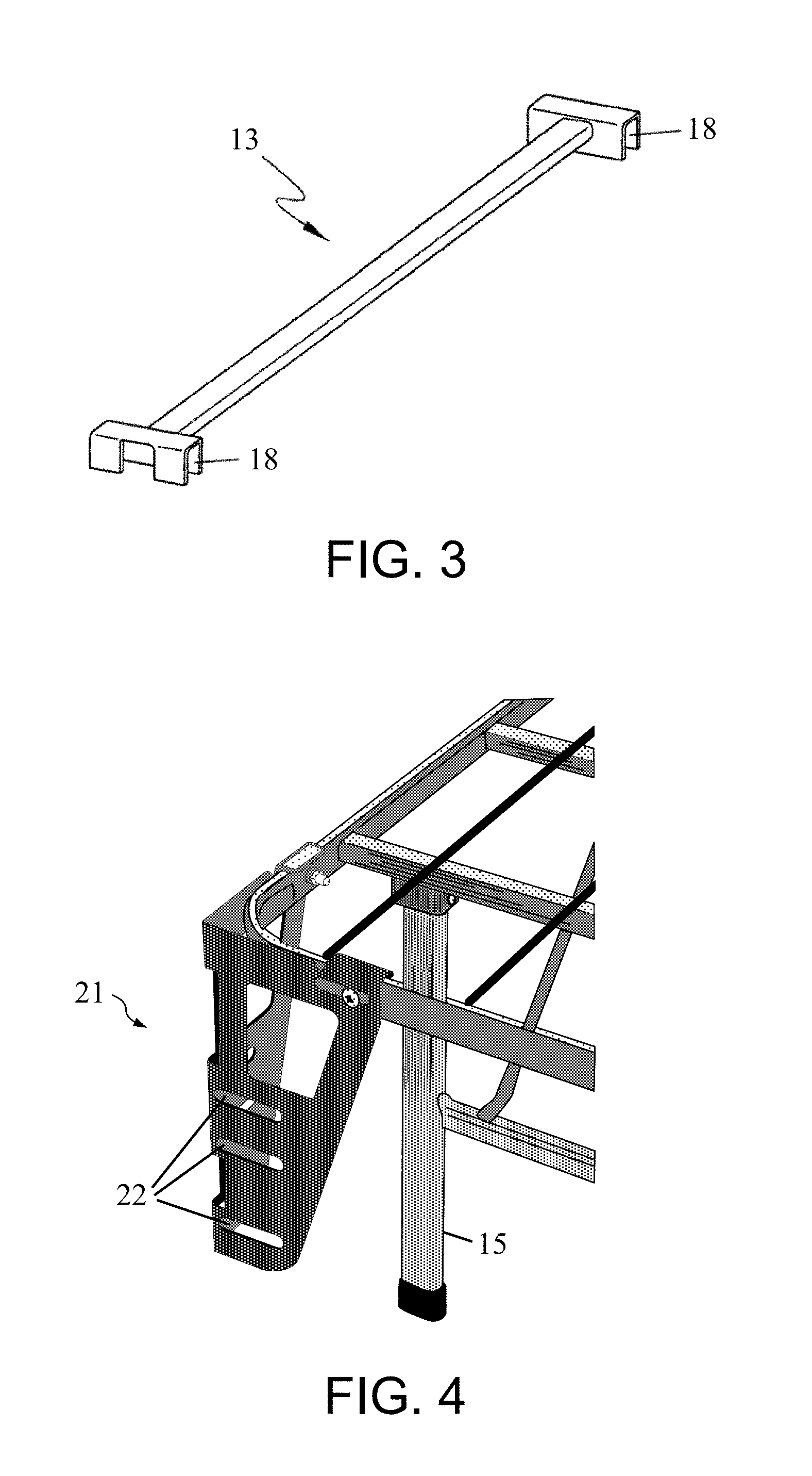
[0029] FIG. 3 is a more detailed view of one of the central connecting bars of the folding bed frame of FIG. 2.
[0030] FIG. 4 is a schematic view of an edge attachment of the bed frame of FIG. 2 to which a headboard can be attached.
[0031] FIG. 5 is a perspective, cut-away view of a king size mattress placed on the folding bed frame of FIG. 2.
[0032] FIG. 6 is a schematic view of another embodiment of the folding bed frame of FIG. 2.
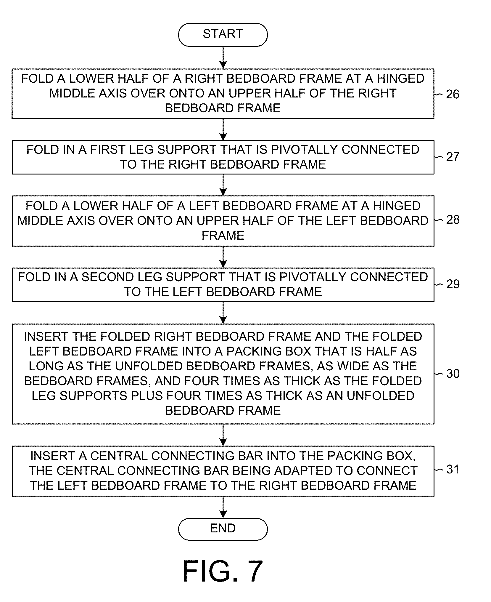
[0033] FIG. 7 is a flowchart illustrating steps of a method of packing the folding bed frame of FIG. 2 into a packing box.
[0034] FIG. 8 is a perspective view of another embodiment of folding bed frames that form a mattress support system with edge attachments that hold a bed skirt taut.
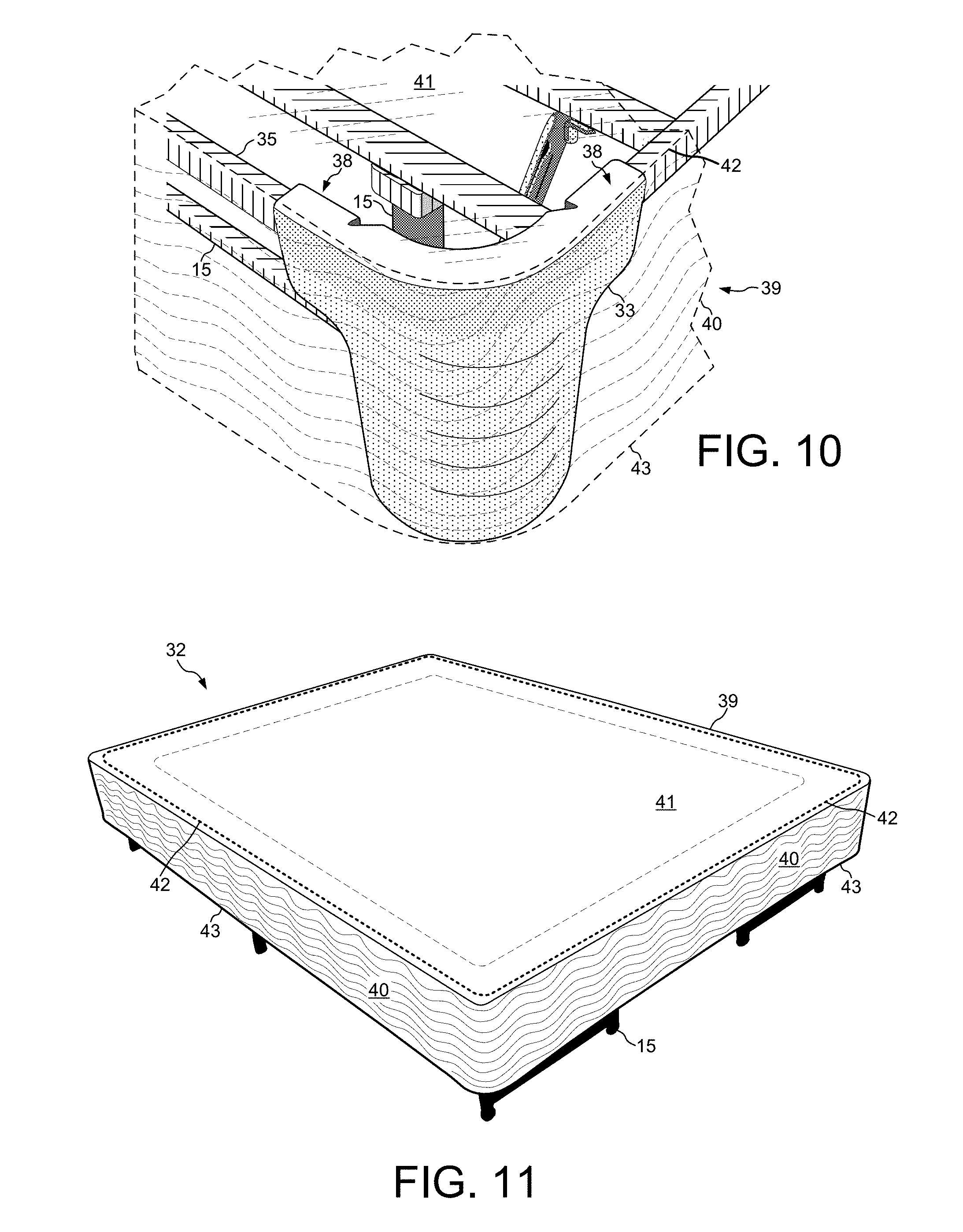
[0035] FIG. 9 shows an edge attachment of FIG. 8 in more detail.
[0036] FIG. 10 is a cut-away view of a bed skirt that has been slipped on over the edge attachment of FIG. 9.
[0037] FIG. 11 is a perspective view of the mattress support system of FIG. 8 after a bed skirt has been slipped down over edge attachments and is held taut.
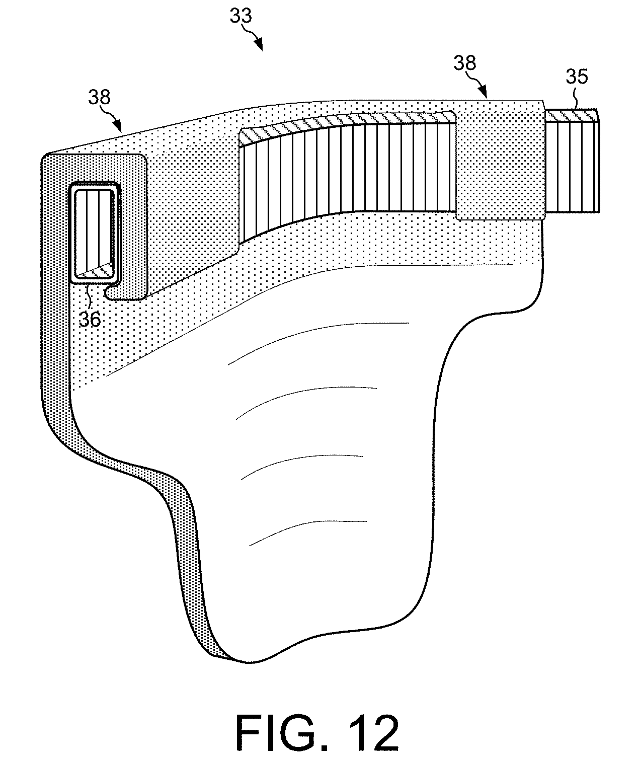
[0038] FIG. 12 is a rear view of the edge attachment of FIG. 9.
[0039] FIG. 13 illustrates a large storage container being slid past the bed skirt and inserted under the mattress support system of FIG. 8.
[0040] FIG. 14 is a perspective view illustrating how storage containers fit underneath the mattress support system of FIG. 8.
[0041] FIG. 15 is a flowchart illustrating steps of a method of assembling the mattress support system of FIG. 8.
[0042] FIG. 16 is a perspective view of a mattress on top of the assembled mattress support system of FIG. 8 after the method of FIG. 15 has been performed.
[0043] FIG. 17 is a perspective view of another embodiment in which solid plastic edge attachments cover the sides of the mattress support system in place of the bed skirt.
[0044] FIG. 18 illustrates a mattress supporting system that includes both edge attachments for holding a bed skirt as well as headboard attachments for attaching a headboard.
[0045] FIG. 19 is a more detailed view of a headboard attachment of FIG. 18.
[0046] FIG. 20 shows the headboard attachment of FIG. 19 from a different angle.
[0047] FIG. 21 shows another embodiment of a headboard attachment attached to a leg and cross bar of a mattress supporting system.
[0048] FIG. 22 shows the headboard attachment of FIG. 21 attached to a mattress supporting system over which a bed skirt has been drawn.
[0049] FIG. 23 shows another embodiment of the mattress supporting system that includes a locking mechanism for the leg supports.
[0050] FIG. 24 shows the upper portion of the bed frame assembly of FIG. 23 in more detail from the underside.
[0051] FIG. 25 shows the locking mechanism of the bed frame assembly of FIG. 24 in more detail.
[0052] FIG. 26 is a schematic diagram from above showing how a bolt on a diagonal strut passes through a channel and into a round opening of a rounded slot in a slotted bracket.
[0053] FIG. 27 is a cross-sectional schematic diagram of a bolt centered in a round opening of the rounded slot of FIG. 26 before a conical washer is lowered into the round opening.
[0054] FIG. 28 is a perspective schematic view of the locking mechanism of FIG. 27 after the conical washer has been tightened by the wing nut into the round opening of the rounded slot.
[0055] FIG. 29 is a perspective view of the locking mechanism of FIG. 27 in which the wing nut has not yet tightened the conical washer all the way down into the round opening of the rounded slot.
[0056] FIG. 30 is a flowchart illustrating steps of a method of assembling the mattress support system of FIG. 23.
[0057] FIG. 31 shows another embodiment of the mattress supporting system that includes hinged brackets to which a headboard can be attached.
[0058] FIG. 32 is a perspective view of the hinged bracket (left side) of FIG. 31 after being attached to the upper-left portion of the mattress supporting system.
[0059] FIG. 33 is a perspective schematic view of the hinged bracket of FIG. 32 in which the first planar metal portion is perpendicular to the second planar metal portion.
[0060] FIG. 34 is a perspective schematic view of the hinged bracket of FIG. 33 in which the first planar metal portion is in the same plane as the second planar metal portion.
[0061] FIG. 35 shows how the first and second planar metal plate portions of the hinged bracket are joined and folded around a hinge axis.
DETAILED DESCRIPTION
[0062] A less costly folding bed frame is disclosed that can accommodate mattresses of various dimensions. A standardized bed frame is provided that can be conveniently adjusted to various mattress widths. The folding bed frame includes a left bed frame assembly and a right bed frame assembly connected by a plurality of central connecting bars. The assembled bed frame forms a bedboard frame and a plurality of legs that are pivotally connected under the bedboard frame. The central connecting bars form part of the bedboard frame and connect the left bed frame assembly to the right bed frame assembly. Each end of each central connecting bar has a U-shaped slot opening downward. A U-shaped slot is clipped down over the inner side edge of a bed frame assembly. In one embodiment, the left and right bed frame assemblies are connected to each other via the central connecting bars through riveting or screwing.
[0063] In the description and claims, terms such as "upper", "lower", "top", "bottom", "up", and "down" are used to describe relative directions and orientations between different parts of the mattress support system, and it is to be understood that the overall structure being described can actually be oriented in any way in three-dimensional space. For example, when a first object is described as being pressed down into a second object, it is to be understood that the first object may in fact be pressed up into the second object. When a first object is referred to as being disposed "over" or "on" a second object, it is to be understood that the first object can be directly on the second object, or an intervening object may be present between the first and second objects.
[0064] The combined width of the pair of bed frame assemblies is narrower than the width of a traditional folding bed frame for a double bed. By connecting the left and right bed frame assemblies directly to each other through bolts, riveting or screwing without using the central connecting bars, a frame for a single bed is provided. A frame for a double bed is provided by spanning the plurality of central connecting bars between the left and right bed frame assemblies. Thus, the standardized left and right bed frame assemblies are adaptable to form frames for mattresses of various dimensions. In addition, the standardized left and right bed frame assemblies reduce the cost of manufacturing bed frames that accommodate different sized mattresses.
[0065] Because the central connecting bars are independent of the standardized left and right bed frame assemblies, the lengths of the bars can be easily varied. Bed frames that can accommodate different widths of mattresses can be manufactured simply by producing central connecting bars with different lengths. Central connecting bars having a specified length can be selected to match the width requirement of each bed without the need to re-manufacture a bedboard frame. Thus, the novel bed frame has a greatly reduced manufacturing cost.
[0066] Especially when configured as a frame for a double bed, the novel folding bed frame is much lighter than conventional folding bed frames with cross and longitudinal bars. The weight of the central connecting bars is less than that of the welded cross and longitudinal bars.
[0067] The novel folding bed frame is also easier to transport than a conventional folding bed frame.
[0068] Conventional frames have a single mattress frame whose size hampers the ease of transport. The novel bed frame is divided into two bed frame assemblies connected by central connecting bars. The novel bed frame can be disassembled into the two separate bed frame assemblies that are easier to carry and transport.
[0069] FIG. 2 shows a novel folding bed frame 10 that can accommodate mattresses of differing dimensions. Bed frame 10 includes a left bed frame assembly 11, a right bed frame assembly 12, and a plurality of central connecting bars 13. Each of frame assemblies 11 and 12 resembles a very narrow folding bed frame. Each of frame assemblies 11 and 12 includes a bedboard frame 14 and a plurality of leg supports 15 pivotally connected under the bedboard frame 11. The bed frame assemblies 11 and 12 stand upon the leg supports 15 when the leg supports are folded out and locked. A bedboard frame is formed by longitudinal bars 16 welded to cross bars 17. In one embodiment, the longitudinal bars 16 are metal rods. Each leg support 15 includes two legs. Three exemplary leg supports 15 are labeled in FIG. 2. Left bed frame assembly 11 differs from a conventional folding bed frame in that assembly 11 is narrower, normally less than half the width of a frame for a double bed.
[0070] FIG. 3 shows an exemplary central connecting bar 13 in more detail. Each central connecting bar is disposed between left bed frame assembly 11 and right bed frame assembly 12. Both ends of each central connecting bar 13 have a U-shaped slot 18 opening downward. The U-shaped slot 18 is clipped down over an inner side edge 19 of one of frame assemblies 11 or 12.
[0071] In another embodiment, the connection between the end of a central connecting bar 13 and an inner side edge 19 is made by inserting a narrow tip of the connecting bar through a hole in the side edge 19. Alternatively, the end of a central connecting bar 13 is bolted to the side edge 19. Other connection means can also be used to connect the central connecting bars to the inner side edges.
[0072] Folding bed frame 10 is shipped from the manufacturer to retail stores in a disassembled condition. Typically, a customer also purchases folding bed frame 10 in a disassembled condition and assembles the bed frame at home in the bedroom where the bed frame will be used. All of the disassembled pieces of folding bed frame 10 fit in a packing box having a length that is about half the length of each bed frame assembly. In the packing box, each bed frame assembly is folded at its middle axis 20, which is hinged. For example, the lower half of each bed frame assembly is folded over onto the upper half of the frame assembly in order to fit in the packing box. The packing box has a width of little more than the width of one bed frame assembly. The thickness of the box is about four times the thickness of the bedboard frame plus four times the thickness occupied by a folded leg support 15. The central connecting bars fit in the packing box between the folded-in leg supports. Thus, the area defined by the length and width of the packing box is less than a quarter of the area of the mattress that fits on the bedboard frame formed by the bed frame assemblies and the central connecting bars.
[0073] To assemble bed frame 10, bed frame assemblies 11 and 12 are first deployed. The bedboard frame 14 of each bed frame assembly is unfolded, and the three leg supports 15 of each frame assembly are folded out and locked. Right bed frame assembly 12 is placed to the right of left bed frame assembly 11. Next, the plurality of central connecting bars 13 are fixedly clipped onto the inner edges 19 of left and right bed frame assemblies 11 and 12 such that the bars transversely span between the left and right bed frame assemblies 11 and 12. The U-shaped slots 18 are clipped down over the metal bars that form the inner edges 19. Next, edge attachments 21 (not shown in FIG. 2) are attached by screws to the upper left corner of left bed frame assembly 11 and to the upper right corner of right bed frame assembly 12.
[0074] FIG. 4 shows the edge attachment 21 attached to the right head corner of right bed frame assembly 12. In this embodiment, edge attachment 21 clips over a head side edge as well as over an outer side edge of right bed frame assembly 12. Then edge attachment 21 is screwed in and hangs down from the side edge of right bed frame assembly 12. A headboard is attached to the edge attachments. Tongues on the headboard slip into slots 22 in edge attachment 21.
[0075] FIG. 5 shows a king size mattress 23 placed on 14 bedboard frame 14 of folding bed frame 10. A headboard 24 is attached to edge attachments 21. FIG. 5 illustrates that the area of bedboard frame 14 formed by the longitudinal bars 16 and cross bars 17 is limited to the sides where the bed frame assemblies are located. The central area of bedboard frame 14 is formed by the central connecting bars 13. Because the weight of the central connecting bars 13 is less than that of the longitudinal bars 16 and cross bars 17, folding bed frame 10 is lighter and less awkward. Folding bed frame 10 is also less awkward than conventional bed frames because the size of the disassembled, folded bed frame inside the packing box is smaller and can be more easily fit inside the trunk of a car or through a doorway.
[0076] Left and right bed frame assemblies 11 and 12 provide support on the side edges of mattresses of every width. Edge support is beneficial, as consumers tend to sit on the side of a mattress before getting in and out of bed. In one embodiment, some unsupported length remains at the foot of the mattress because the length of left and right bed frame assemblies 11 and 12 fits the length of a single mattress, and a headboard is attached to the head of the bed frame assemblies. In another embodiment, a central connecting bar connects the foot side edges of left and right bed frame assemblies 11 and 12 and provides support for mattress 23 at the foot of the bed.
[0077] In addition, the manufacturing cost of folding bed frame 10 is reduced because bed frame assemblies 11 and 12 are standardized, and the length of the central connecting bars 13 can be adjusted. In one embodiment, central connecting bars 13 having a length that is appropriate for the width of a certain mattress are included in the packing box. For example, shorter connecting bars are included in the packing box of a bed frame for a queen size mattress than are included in the box for a king size mattress. In another embodiment, the central connecting bars are conveniently adjustable by allowing one side of each connecting bar to telescope into the other side of the connecting bar. A screw from the outer bar then tightens into the inner bar to fix the length of the connecting bar. Alternatively, a connecting bar is made adjustable by sliding a smaller U-shaped bar inside a larger, outer U-shaped bar.
[0078] FIG. 6 shows another embodiment of folding bed frame 10 in which no central connecting bars are used. Left and right bed frame assemblies 11 and 12 are placed directly adjacent to each other. The inner side edges 19 of the bed frame assemblies 11 and 12 are attached to each other by bolts 25 and nuts. Alternatively, the bed frame assemblies 11 and 12 can be connected by screws or rivets. The bed frame of FIG. 6 has a width that is appropriate for a narrow mattress, such as an extra-long college twin mattress that measures 38 inches by 84 inches. Thus, the same standardized bed frame assemblies 11 and 12 form a bedboard frame 14 that supports mattresses of different dimensions. Not only is the manufacturing cost reduced, but the disassembled folding bed frame can be more conveniently packaged and transported.
[0079] FIG. 7 is a flowchart illustrating steps 26-31 of a method of packing folding bed frame 10 into a packing box that is conveniently sized for transporting. In a first step 26, a lower half of the bedboard frame 14 of right bed frame assembly 12 is folded over onto an upper half of the bedboard frame. Bedboard frame 14 is folded over at a hinge at middle axis 20.
[0080] In step 27, a first leg support 15 that is pivotally connected to the bedboard frame 14 of right bed frame assembly 12 is folded in. In step 28, a lower half of the bedboard frame 14 of left bed frame assembly 11 is folded over onto an upper half of the bedboard frame. In step 29, a second leg support 15 that is pivotally connected to the bedboard frame 14 of left bed frame assembly 11 is folded in. In step 30, the folded bedboard frame of right bed frame assembly 12 and the folded bedboard frame of left bed frame assembly 11 are inserted into a packing box. The packing box is about half as long as the unfolded bedboard frame of right bed frame assembly 12. The packing box has a width of little more than the width of right bed frame assembly 12. The packing box is about four times as thick as the folded first leg support plus four times as thick as the unfolded bedboard frame of right bed frame assembly 12. In step 31, a central connecting bar 13 is inserted into the packing box. The central connecting bar 13 is adapted to connect the bedboard frame of left bed frame assembly 11 to the bedboard frame of right bed frame assembly 12.
[0081] FIG. 8 illustrates another embodiment of a folding bed frame that includes edge attachments for holding a bed skirt. The folding bed frame of FIG. 8 provides a mattress supporting system 32 that performs the functions of both a conventional box spring and a conventional metal bed frame with wood rails. Thus, mattress supporting system 32 can replace conventional bed frames and box springs. Mattress supporting system 32 includes left bed frame assembly 11, right bed frame assembly 12, and central connecting bars 13. Each of the bed frame assemblies 11 and 12 includes a bedboard frame 14. The bed frame assemblies 11 and 12 stand upon leg supports 15 when the leg supports are folded out and locked. Each bed frame assembly has a hinge at its middle axis 20 at which a lower portion of the assembly unfolds from an upper portion.
[0082] Mattress supporting system 32 includes an edge attachment 33 attached to the right foot corner 34 (the lower right corner) of right bed frame assembly. (For simplicity, the remaining edge attachments are not shown in FIG. 8, but are illustrated in subsequent figures.) Edge attachment 33 clips over a foot side edge 35 and an outer side edge 36 of right bed frame assembly 12. Edge attachment 33 is adapted to hold a bed skirt taut around both bed frame assemblies of mattress supporting system 32 when the bed frame assemblies are resting on the extended leg supports 15.
[0083] In one embodiment of mattress supporting system 32, edge attachment 33 and the other edge attachments (not shown) slant at an angle 37 down and away from the bed frame assemblies when no bed skirt is being held such that a bed skirt that is slipped on over the slanted edge attachments is held taut. Edge attachment 33 slants down at an angle 37 that is about five to ten degrees from vertical. The bottom edge of the bed skirt is held taut as the bed skirt pulls the bottoms of the edge attachments inward. Thus, the long side of edge attachment 33 is oriented vertically when the bed skirt is slipped over mattress supporting system 32.
[0084] FIG. 9 shows edge attachment 33 in more detail. In one embodiment, edge attachment 33 is made of hard molded plastic. Edge attachments at the foot of a bed are preferably made of plastic instead of metal to avoid injury to the shins, feet and children as consumers walk around the foot of mattress support system 32. Plastic edge attachments are also less expensive to manufacture than metal edge attachments. In addition, plastic edge attachments are lighter weight than metal edge attachments and are therefore less expensive to transport. Where stronger edge attachments are required to hold both a bed skirt and a headboard, metal is used. Clips 38 on edge attachment 33 clip down over foot side edge 35 and outer side edge 36 such that no screws, bolts or nuts are required to attach edge attachment 33 to the side edges.
[0085] FIG. 10 is a cut-away view of a bed skirt 39 that has been slipped on over slanted edge attachment 33. Bed skirt 39 has a skirt portion 40 and center fabric 41. Skirt portion 40 has an upper edge 42 and a lower edge 43. While bed skirt 39 is slipped over the slanted edge attachments on the four corners of mattress support system 32, the edge attachments hold lower edge 43 of skirt portion 40 taut. Skirt portion 40 gives the appearance of a covering of a solid box spring. In one embodiment, center fabric 41 is made of a non-skid fabric such that a mattress placed on mattress support system 32 does not slip.
[0086] FIG. 11 shows bed skirt 39 after being slipped down over edge attachment 33 and the other edge attachments such that bed skirt 39 is held taut around bed frame assemblies 11 and 12 when the bed frame assemblies are standing on the unfolded leg supports 15. The edge attachments hold bed skirt 39 such that more than half of each leg support 15 is not visible behind bed skirt 39 when the bed frame assemblies are resting on the extended leg supports 15. Thus, mattress support system 32 appears to be a solid box spring sitting on short legs.
[0087] Although mattress support system 32 has an appearance similar to a conventional box spring, mattress support system 32 has several advantages over a conventional box spring that is supported by the metal rails of a conventional bed frame. First, mattress support system 32 is easier to move than a conventional box spring. Whereas a conventional box spring is constructed with a unitary wood frame that cannot be bent or disassembled into pieces, mattress support system 32 can be delivered in a relatively small packing box. Consequently, mattress support system 32 can be transported in an elevator and moved around the bend in a staircase, whereas a queen or king size box spring may be too large or awkward. Mattress support system 32 fits in a packing box that is about half as long as the unfolded bed frame assemblies and about as wide as the width of one bed frame assembly.
[0088] Second, mattress support system 32 is lighter than a conventional bed frame and box spring, and thus is both less expensive and easier to transport. The wood frame of a conventional box spring has solid sides, which weigh more than the edge attachments of mattress support system 32 over which the fabric of the bed skirt is stretched. Wood beams of a conventional box spring form both a top surface and a bottom surface, whereas the bottom of mattress support system 32 remains open. The leg supports of mattress support system 32 are lighter than a conventional metal bed frame with wooden rails upon which the conventional box spring sits.
[0089] Third, mattress support system 32 is quieter than a conventional box spring sitting on wooden rails of a bed frame. As a person moves on a mattress, the joints in the wood of the box spring squeak. In addition, movement of the box spring over the wooden rails also makes noise. The metal construction of mattress support system 32 is less likely to make noise as a person moves on a mattress supported by the support system.
[0090] Fourth, mattress support system 32 provides a significant amount of storage space beneath the supported mattress. Because the wood frame of a conventional box spring has solid sides and beams forming top and bottom surfaces, the volume inside a conventional box spring cannot be accessed for storage. On the other hand, mattress support system 32 is open at the bottom and permits that space between the leg supports 15 to be used for storage.
[0091] FIG. 12 is a rear view of edge attachment 33 of FIG. 9. In the view of FIG. 12, foot side edge 35 and outer side edge 36 have been cut away. FIG. 12 illustrates how a clip 38 clips down over and locks to outer side edge 36. Clip 38 holds edge attachment 33 firmly to the side edges without using separate attachment pieces, such as screws, bolts or nuts.
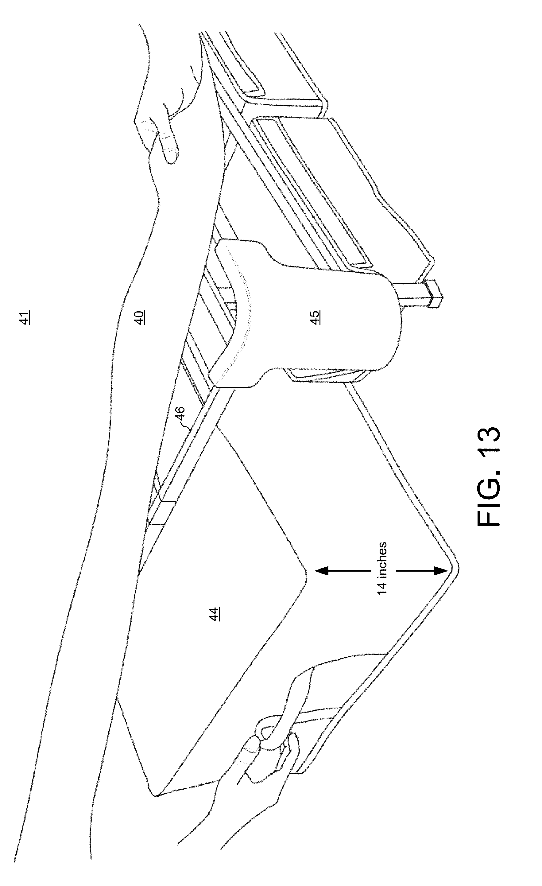
[0092] FIG. 13 illustrates the significant storage area available beneath a mattress supported by mattress support system 32. A large storage container 44 can be slid past bed skirt 39 and inserted under mattress support system 32. Storage container 44 has a floor height of more than twelve inches and would not fit under the rail of a conventional bed frame that stands only a few inches off the floor. A bed frame assembly and an edge attachment 45 are adapted to allow storage container 44 to slide under the bed frame assembly when the taut bed skirt 39 is stretched at the middle of a side between edge attachments. In FIG. 13, skirt portion 40 of bed skirt 39 has been detached from left foot edge attachment 45 to allow storage container 44 to be slid under mattress support system 32 past the skirt portion 40. In the embodiment of FIG. 13, storage container 44 has a floor height of fourteen inches and slides below outer side edge 46.
[0093] FIG. 14 is a picture of mattress support system 32 illustrating how twelve storage containers fit underneath bed frame assemblies 11 and 12 and central connecting bars 13. For purposes of illustration, mattress support system 32 is shown in FIG. 14 without bed skirt 39. In addition to large storage container 44, which fits under left bed frame assembly 11, there is an even bigger storage container 47 that fits under right bed frame assembly 12 and central connecting bars 13. A smaller storage container 48 slides under the side edges and under the diagonal support bars 49 near the foot of the mattress support system 32.
[0094] In the embodiment of FIG. 14, mattress support system 32 has six edge attachments: four at the corners and two at the middle of the sides. In addition to left foot edge attachment 45 and edge attachment 33 at the bottom right corner of mattress support system 32, FIG. 14 also shows a side edge attachment 50. Side edge attachment 50 stabilizes skirt portion 40 of bed skirt 39 at the middle of outer side edge 46 while skirt portion 40 is being held taut by left foot edge attachment 45 and a left head edge attachment 51. In one embodiment, the bottom of side edge attachment 50 holds lower edge 43 of skirt portion 40 down such that lower edge 43 forms a straight line from the bottom of left foot edge attachment 45 to the bottom of left head edge attachment 51.
[0095] FIG. 15 is a flowchart illustrating steps 54-61 of a method of setting up mattress support system 32. In a first step 54, the contents are removed from a packing box containing mattress support system 32. In the embodiment of FIG. 8, the packing box includes left bed frame assembly 11, right bed frame assembly 12, seven central connecting bars 13, six edge attachments 33, 45, 50-53 and bed skirt 39. Leg supports 15 are part of bed frame assemblies 11 and 12. Thus, right bed frame assembly 12 and edge attachment 33 are removed from the packing box.
[0096] In a step 55, the upper portion of each bed frame assembly is unfolded from the lower portion at hinges located along middle axis 20. In the folded condition in the packing box, the leg supports are folded into the outer sides of each folded bed frame assembly. In step 55, the upper portion of right bed frame assembly 12 is unfolded from the lower portion of bed frame assembly 12.
[0097] In a step 56, the leg supports 15 are unfolded. For example, a leg support 62 that is pivotally connected to the upper portion of right bed frame assembly 12 is unfolded and locked into place.
[0098] In a step 57, the unfolded bed frame assemblies 11 and 12 are stood on the unfolded leg supports 15. For example, the unfolded right bed frame assembly 12 is stood on unfolded leg supports 15, including unfolded and locked leg support 62.
[0099] In a step 58, central connecting bars 13 are fixedly clipped onto the inner side edges of bed frame assemblies 11 and 12 such that the bars transversely span between the bed frame assemblies.
[0100] In a step 59, the edge attachments are attached to the outer corners and to the middle of the outer sides of bed frame assemblies 11 and 12. For example, edge attachment 33 is clipped down over the side edges at the right foot corner of mattress support system 32. Edge attachment 50 is clipped down over outer side edge 46 halfway between left foot edge attachment 45 and left head edge attachment 51.
[0101] In a step 60, a bed skirt is slipped down over bed frame assemblies 11 and 12 and over the edge attachments. The four edge attachments 33, 45, 51, 52 at the corners of mattress support system 32 hold the bed skirt taut around the bed frame assemblies when the bed frame assemblies are standing on the unfolded leg supports. For example, bed skirt 39 is slipped down over edge attachment 33 such that skirt portion 40 of bed skirt 39 is held taut around right bed frame assembly 12. When skirt portion 40 is pulled down over the edge attachments, center fabric 41 is also pulled taut over the bedboard frames of bed frame assemblies 11 and 12.
[0102] In a step 61, a mattress 63 is placed on center fabric 41 over the assembled mattress support system 32.
[0103] FIG. 16 shows the assembled mattress support system 32 after the method of FIG. 15 has been performed. Mattress support system 32 has been set up with mattress 63 resting on top of center fabric 41.
[0104] In another embodiment, another type of edge attachment is attached to the left head corner and to the right head corner of mattress support system 32. In this embodiment, the edge attachments on the head corners of mattress support system 32 are made of metal and resemble edge attachment 21 of FIG. 4. The metal edge attachments either screw into or are clipped down over the side edges. Then bed skirt 39 is slipped down over the two plastic edge attachments at the foot corners and over the two metal edge attachments at the head corners of mattress support system 32. Slits are made in the head side of skirt portion 40 to allow tongues on a headboard to slip into slots in the metal edge attachments. Thus, the metal edge attachments are used both to hold skirt portion 40 taut around mattress support system 32, as well as to hold a headboard. As shown in FIG. 4, the metal edge attachment is adapted to hold a headboard that attaches to the edge attachment only at locations below the head side edge of the bed frame assembly.
[0105] FIG. 17 shows yet another embodiment in which the edge attachments cover the sides of mattress support system 32 in place of bed skirt 39. The embodiment of FIG. 17 has solid plastic edge attachments 64 that snap down with clips 65 over the side edges. Edge attachments 64 do not attach to the side edges at the corners, as do edge attachments 33, 45, 51, 52, but rather attach along a large section of each side edge and meet at the corners. In the embodiment of FIG. 17, there are two edge attachments per side edge. The hard plastic of edge attachments 64 may be made in different colors so as to provide beds in a variety of colors. When the sides of mattress support system 32 are covered by edge attachments 33, 45, 51, 52, mattress support system 32 has the appearance of a platform bed.
[0106] FIG. 18 illustrates another embodiment of a mattress supporting system 66 that includes both edge attachments for holding a bed skirt and separate headboard attachments for attaching a headboard. Mattress supporting system 66 includes six solid plastic edge attachments that clip over the side edges, including left foot edge attachment 45, right feet edge attachment 33, left head edge attachment 51, right head edge attachment 52, left side edge attachment 50 and right side edge attachment 53. The plastic edge attachments 51-52 are not strong enough to hold the weight of most headboards, so dual purpose metal edge attachment of the type shown in FIG. 4 would be required both to hold a bed skirt taut and to support a headboard. A headboard is attached to dual purpose edge attachment 21 of FIG. 4 by slipping tongues on the headboard into the slots 22 in edge attachment 21. Alternatively, bolts on the headboard pass through the slots 22 and are fastened by nuts or wing nuts on the opposite side of edge attachment 21.
[0107] Where edge attachment 21 holds a bed skirt, however, attaching a headboard onto edge attachment 21 requires slitting the bed skirt and passing the tongues or bolts through the slits. Cutting or puncturing the bed skirt may be considered undesirable and inconvenient. Moreover, the headboard must be removed in order to remove and replace the bed skirt. Mattress supporting system 66 includes a metal headboard attachment 67 that is separate from the plastic edge attachments 33, 45 and 50-53 that hold the bed skirt. Headboard attachment 67 permits a bed skirt to be replaced without removing the headboard. In addition, the bed skirt need not be punctured or slit in order to allow bolts or tongues to pass from the headboard through the bed skirt to the edge attachments.
[0108] Mattress supporting system 66 includes left bed frame assembly 11, right bed frame assembly 12, and central connecting bars 13. The bed frame assemblies 11 and 12 stand upon leg supports 15 when the leg supports are folded out and locked. Each leg support 15 includes two legs and a cross bar. For example, the upper left leg support 15 includes an outer leg 68 and a cross bar 69. Headboard attachment 67 attaches to leg 68 and extends under the bed skirt laterally past head side edge 70. Mattress supporting system 66 also includes a second metal headboard attachment (not shown in FIG. 18) that is a mirror image of headboard attachment 67 and that attaches to the outer leg of the upper right leg support. The headboard attaches to headboard attachment 67 only at locations below head side edge 70 of left bed frame assembly 11. The headboard also attaches to the second headboard attachment at locations below the head side edge of right bed frame assembly 12.
[0109] FIG. 19 shows headboard attachment 67 of FIG. 18 in more detail. Headboard attachment 67 has a main face 71 with slots 72 and a side surface 73. Side surface 73 prevents a person from cutting her shin on the edge of main face 71 while walking around the upper left corner of mattress supporting system 66 when a headboard is not attached to headboard attachment 67. Tongues on a headboard slip into the slots 72 in headboard attachment 67. Alternatively, bolts attached to the headboard pass through the slots 72 and are tightened by nuts or wing nuts. Headboard attachment 67 also includes a separate fastening portion 74 and an angle bracket 75 that protrudes from a flange 76. Fastening portion 74 is used to clamp headboard attachment 67 to leg 68 by tightening wing nuts 77. When headboard attachment 67 is tightened around leg 68, angle bracket 75 rests on cross bar 69 of the leg support and prevents a heavy headboard from causing headboard attachment 67 to slip down leg 68.
[0110] FIG. 20 is a view of headboard attachment 67 from a different angle. FIG. 20 shows fastening portion 74 loosened from the main body of headboard attachment 67. Leg 68 is clamped between flange 76 and fastening portion 74 using bolts and wing nuts.
[0111] FIG. 21 shows another embodiment of headboard attachment 67 attached to leg 68 and cross bar 69. The embodiment of FIG. 21 does not include a side surface 73. The view of FIG. 21 is shown without left head edge attachment 51.
[0112] FIG. 22 shows the embodiment of FIG. 21 attached to a mattress supporting system over which a bed skirt 78 has been drawn. Bed skirt 78 has skirt portion 40 and center fabric 41. FIG. 22 shows upper edge 42 and lower edge 43 of skirt portion 40. Slanted edge attachment 51 holds lower edge 43 of skirt portion 40 taut. Skirt portion 40 gives the appearance of a covering of a solid box spring. FIG. 22 also shows a dashed outline of a headboard 79 that is attached to headboard attachment 67 and to the second headboard attachment located at the right head corner of the mattress supporting system.
[0113] FIG. 23 illustrates one of the bed frame assemblies of another embodiment of the mattress supporting system 66 that includes locking mechanisms for the upper and lower leg supports. In the embodiment of FIG. 18, a separate headboard attachment 67 is attached to upper leg support 15 and must support the heavy headboard 79. Thus, the leg support 15 must support the combined weight of the mattress, the occupant of the bed and the headboard. The bed frame assembly 80 of FIG. 23 includes sturdy diagonal struts 81-84 with locking mechanisms 85-88, respectively, that prevent the upper and lower leg supports 89-90 from angling away from vertical under the combined weight.
[0114] Bed frame assembly 80 includes a plurality of leg supports 89-91 pivotally connected to a bedboard frame 92. Assembly 80 stands upon the leg supports 89-91 when the leg supports are folded out and locked. Bedboard frame 92 is formed by longitudinal bars 93-96 welded to cross bars 97-104. Each leg support 89-91 includes two legs and a support bar. For example, upper left leg support 89 includes two legs 105-106 and support bar 107. Bed frame assembly 80 has a hinge at its middle axis at which the lower portion of bedboard frame 92 unfolds from the upper portion. In the embodiment of FIG. 23, the middle axis lies along a middle plane formed by the two legs 108-109 of the middle leg support 91. Hinges on either side of the middle plane pivotally attach the longitudinal bars 93-96 of the upper and lower portions of the bedboard frame 92 to the middle leg support 91. The hinges are fixedly attached to the middle leg support 91. The upper and lower leg supports 89-90 are pivotally attached to cross bars 97 and 104, respectively.
[0115] After the upper portion of assembly 80 is unfolded from the lower portion, the upper and lower leg supports 89-90 can be unfolded. For example, upper leg support 89 that is pivotally connected to the upper portion of bedboard frame 92 is unfolded and locked into place by diagonal struts 81-82 and locking mechanisms 85-86. Before upper leg support 89 is unfolded, the plane of legs 105-106 is parallel to the plane of the upper portion of bedboard frame 92. In addition, the diagonal struts 81-82 are not yet attached to cross bar 98, but are instead parallel to the plane of legs 105-106. Thus, the diagonal struts 81-82 are pivotally attached to support bar 107 and are rotated out of the plane of legs 105-106 after upper leg support 89 is unfolded.
[0116] FIG. 24 shows the upper portion of bed frame assembly 80 in more detail from the underside of bedboard frame 92 after upper leg support 89 has been unfolded and after the diagonal struts 81-82 have been rotated out of the plane of legs 105-106. Struts 81-82 are rotated in opposite directions to reach slotted brackets 110-111 attached to cross bar 98. For example, diagonal strut 82 is rotated clockwise in the perspective of FIG. 24 to reach a slotted bracket 110 that is welded to cross bar 98. The locking mechanism 86 is formed between slotted bracket 110 and the end of diagonal strut 82.
[0117] FIG. 25 shows the locking mechanism 86 in more detail from the underside of bedboard frame 92 before diagonal strut 82 has completely reached slotted bracket 110. A bolt 112 is fixedly attached to the end of diagonal strut 82. A conical washer 113 slides along bolt 112 and is held on the bolt by a wing nut 114. FIG. 25 also shows a conical washer and wing nut on a bolt at the end of the other diagonal strut 81. Diagonal strut 81 is still in the plane of upper support leg 89 and has not yet been rotated so that the end of the strut reaches the slotted bracket 111. Diagonal strut 82 is being rotated such that bolt 112 will pass into a rounded slot 115 in slotted bracket 110. Rounded slot 115 has a channel 116 that is only slightly wider than the diameter of bolt 112. A round opening 117 at the end of the channel 116 has a diameter larger than the width of the channel.
[0118] FIG. 26 is a schematic diagram from above showing how bolt 112 passes through channel 116 and into the round opening 117 of rounded slot 115 as diagonal strut 82 is rotated. Wing nut 114 is not shown in FIG. 26. Conical washer 113 is raised above slotted bracket 110 as bolt 112 passes through channel 116. Then the coned portion of conical washer 113 fits into the round opening 117 once bolt 112 is centered in the round opening. From the upside-down perspective of FIG. 25, the coned portion fits down into the round opening 117.
[0119] FIG. 27 is a cross-sectional schematic diagram of bolt 112 centered in the round opening 117 of rounded slot 115 before conical washer 113 is lowered into the round opening 117. In the right-side-up orientation of FIG. 23, conical washer 113 rises up into the round opening 117 as wing nut 114 is tightened. In one embodiment, conical washer 113 has a coned portion and a cylindrical portion. The diameter of the cylindrical portion of conical washer 113 is larger than the diameter of the round opening 117. In another embodiment, conical washer 113 has only the coned portion, and the maximum diameter of the coned portion is larger than the diameter of the round opening 117. After conical washer 113 is lowered into round opening 117 and wing nut 114 is tightened to prevent conical washer 113 from rising up, the sides of the coned portion of conical washer 113 prevent bolt 112 from passing out of the narrower channel 116.
[0120] FIG. 28 is a perspective schematic view of locking mechanism 86 after conical washer 113 has been tightened by wing nut 114 into the round opening 117 of rounded slot 115. The sides of the lower coned portion of conical washer 113 press against the sides of the round opening 117. FIG. 28 shows that the largest diameter of the coned portion is larger than the diameter of the round opening 117.
[0121] FIG. 29 is a perspective view of locking mechanism 86 in which bolt 112 has been rotated into rounded slot 115 but conical washer 113 has not yet been tightened by wing nut 114 all the way down into the round opening 117.
[0122] FIG. 30 is a flowchart illustrating steps 118-12X of a method of setting up mattress support system 66 of FIG. 23. In a first step 118, the contents are removed from a packing box containing mattress support system 66. In the embodiment of FIG. 23, the packing box includes only the components of bed frame assembly 80. Bed frame assembly 80 includes the upper and lower portions of bedboard frame 92, leg supports 89-91, diagonal struts 81-84 and locking mechanisms 85-88.
[0123] In a step 119, the upper portion of bed frame assembly 80 is unfolded along a middle axis from the lower portion. The upper portion and the lower portion are pivotally connected at a hinge. In the folded condition in the packing box, the leg supports 89-90 are folded into the bottom sides of the upper and lower portions of the bed frame assembly. Each leg support has two legs disposed in a plane, and the two legs are connected by a support bar.
[0124] In a step 120, the leg supports 89-90 are unfolded. For example, upper leg support 89 that is pivotally connected to the upper portion of bedboard frame 92 is unfolded to an orientation perpendicular to the upper portion. Middle leg support 91 need not be separately unfolded because the middle support is left standing when the upper and lower portions of bedboard frame 92 are unfolded from one another. After the upper and lower leg supports 89-90 are unfolded, the diagonal struts 81-84 can be conveniently locked into place using the locking mechanisms 85-88.
[0125] In a step 121, the diagonal struts 81-82 are rotated out of the planes of the leg supports 89-90. For example, diagonal strut 81 that is pivotally attached to support bar 107 of upper leg support 89 is rotated out of the plane of the leg support, and diagonal strut 82 that is pivotally attached to support bar 107 is also rotated out of the plane of upper leg support 89. Bolt 112 is fixedly attached to an end of diagonal strut 82 opposite support bar 107, and conical washer 113 passes over bolt 112 and is held on bolt 112 by wing nut 114.
[0126] In a step 122, the bolts at the ends of the diagonal struts are rotated into rounded slots in slotted brackets that are attached to cross bars. For example, bolt 112 is inserted through channel 116 and into round opening 117 of rounded slot 115 in slotted bracket 110 by rotating diagonal strut 82. Slotted bracket 110 is attached to cross bar 98 of bedboard frame 92.
[0127] In a step 123, the wing nuts are tightened so as to press the coned portions of the conical washers into the round openings in the slotted brackets, which prevents the bolts from slipping out of the rounded slots and thereby locks the unfolded leg supports in place. For example, wing nut 114 is tightened so as to press conical washer 113 down into round opening 117 such that the sides of the lower coned portion of conical washer 113 press against the sides of the round opening 117.
[0128] In a step 124, the unfolded bed frame assembly 80 is stood on the unfolded and locked leg supports 89-91. For example, the unfolded bed frame assembly 80 is stood on the leg supports 89-91, including the unfolded and locked leg support 89.
[0129] In a step 125, a headboard attachment is attached to upper leg support 89. Because leg support 89 is locked into place by diagonal struts 81-82 and locking mechanisms 85-86, the leg support is stable enough to hold the headboard attachment and the headboard.
[0130] In a step 126, a mattress is placed on top of the assembled bed frame assembly 80.
[0131] FIG. 31 is a perspective view of two hinged brackets for headboard support of the bed frame assembly 80 of FIG. 23. The view of FIG. 31 is from the upper side of the bed frame assembly 80. The upper side of the bedboard frame 92 includes an upper side edge bar 128 and the two longitudinal bars 93 and 94. The longitudinal bars 93 and 94 are also referred to as outer side edge bars. A hinged bracket (right side) 129 is secured to the longitudinal bar 94 and the upper side edge bar 128. A hinged bracket (left side) 130 is secured to the longitudinal bar 93 and the upper side edge bar 128. Both hinged brackets 129 and 130 have the same design and are manufactured in the same way. In the embodiment shown in FIG. 31, the hinged brackets 129 and 130 are secured to the bedframe assembly 80 using screws.
[0132] FIG. 32 shows the upper-left portion of bed frame assembly 80 in more detail after the hinged bracket (left side) 130 has been unfolded and secured to the bedboard frame 92. The hinged bracket 130 includes a first planar metal plate portion 131, a second planar metal plate portion 142, a first hinge 153 and a second hinge 157. The first planar metal plate portion 131 includes a first lip 134, a first slot 135, a second slot 136, and a third slot 137. The first lip 134 rests on top of the upper side edge bar 128. The first planar metal plate portion is screwed into an outer edge of upper side edge bar 128 through the third slot 137. The first planar metal plate portion 131 hangs down from the upper side edge bar 128. In one embodiment, the headboard of the bed frame assembly 80 is attached to the hinged bracket 130 below the upper side edge bar 128.
[0133] The second planar metal plate portion 142 includes a second lip 145, a fourth slot 146, a fifth slot 147, and a sixth slot 148. The second lip 145 rests on top of the longitudinal bar 93. The second planar metal plate portion 142 is screwed into an outer edge of the longitudinal bar 93 through the sixth slot 148. The first planar metal plate portion 131 is pivotally attached to the second planar metal plate portion 142 at the second hinge 157.
[0134] Similarly, the hinged bracket (right side) 129 mirrors the components of the hinged bracket (left side) 130. For example, the hinged bracket 129 has a first metal plate portion that includes a first lip, a first slot, a second slot, and a third slot. In this example, the first lip rests on top of the longitudinal bar 94, and the first planar metal portion is screwed into an outer edge of the longitudinal bar 94. Furthermore, in this example, the hinged bracket 129 has a second metal plate portion that includes a second lip, a fourth slot, a fifth slot, and a sixth slot, wherein the second lip rests on top of the upper side edge bar 128 and the second planar metal portion is screwed into an outer edge of the upper side edge bar 128 (see FIG. 31). In the embodiment shown in FIG. 32, the first planar metal plate portion 131 is oriented perpendicular to the second planar metal plate portion 142, and the hinged bracket 130 is supported by the bed frame assembly 80. The hinged bracket 129 is also supported by the bed frame assembly 80 in a similar fashion to that of the hinged bracket 130.
[0135] Furthermore, the hinged brackets 129 and 130 are adapted to hold a headboard of a bed. For example, the hinged bracket 130, shown in FIG. 32, includes the first slot 135 and the second slot 136, wherein each slot is capable of receiving a tongue of the headboard. In another example, the tongue of the headboard slides into the fourth slot or the fifth slot of the hinged bracket 129.
[0136] FIG. 33 is a perspective schematic view of the hinged bracket (left side) 130. The view of FIG. 33 is the reverse view of FIG. 32 without the bedframe assembly 80. The hinged bracket 130 includes the first planar metal plate portion 131, the second planar metal plate portion 142, the first hinge 153, and the second hinge 157.
[0137] The first planar metal plate portion 131 includes a first upper edge 132, a first descending edge 133, the first lip 134, the first slot 135, the second slot 136, the third slot 137, a seventh slot 158, an eighth slot 159, and a first opening 162. The first planar metal plate portion 131 also includes a first curved section 140 and a third curved section 141, as shown in FIG. 34. Each curved section is made from a rolled tongue that extends from the first planar metal plate portion 131 opposite the first descending edge 133. The first curved section 140 and the third curved section 141 together form a first portion of the first hinge 139, as shown in FIG. 33.
[0138] The second planar metal plate portion 142 includes a second upper edge 143, a second descending edge 144, the second lip 145, the fourth slot 146, the fifth slot 147, the sixth slot 148, a ninth slot 160, a tenth slot 161, a second opening 163. The second planar metal plate portion 142 also includes a second curved section 151 and a fourth curved section 152 (see FIG. 34). The second curved section 151 and the fourth curved section 152 together form a second portion of the first hinge 150 as shown in FIG. 33.
[0139] The first hinge 153 includes the first portion 139 of the first hinge, the second portion 150 of the first hinge, a pin 154, and a nut 155. The pin 154 slides through the first curved section 140, the second curved section 151, the third curved section 141, and the fourth curved section 152. The lower end of the pin 154 is secured using the nut 155. The first portion 139 of the hinge adjoins the second portion 150 of the hinge at a hinged edge of the hinged bracket 130. The first planar metal plate portion 131 and the second planar metal plate portion 142 are adjoined at a hinge axis 156. The first planar metal plate portion 131 and second planar metal plate portion 132 rotate axially around the hinge axis 156. The first planar metal plate portion 131 has a length along its hinged edge of less than fourteen inches.
[0140] The second hinge 157 comprises a first portion of the second hinge 164, a second portion of the second hinge 165, a pin 179 and a nut 180. The first portion of the second hinge 164 includes a fifth curved section 166 and a seventh curved section 167, which are part of the first planar metal plate portion 131 (see FIG. 34). The second portion of the second hinge 165 includes a sixth curved section 168 and an eighth curved section 169, which are part of the second planar metal plate portion 142 (see FIG. 34). The pin 179 slides through both the first portion 164 and the second portion 165 of the second hinge 157 and is secured using the nut 180. The first hinge 153 and the second hinge 157 are disposed along the hinged axis 156.
[0141] In one embodiment, the first planar metal plate portion 131 has a top half and a bottom half. The top half of the first planar metal plate portion 131 includes the first upper edge 132, the first lip 134, the third slot 137, the first portion of the first hinge 139, and the first opening 162. The bottom half of the first planar metal plate portion 131 includes the first slot 135, the eighth slot 159, and the first portion of the second hinge 164. The first lip 134 aligns the first upper edge 132 of the first planar metal plate portion 131 with the upper side edge bar 128 (see FIG. 32). The first upper edge 132 of the first planar metal plate portion 131 is perpendicular to the first portion of the first hinge 139. The bottom half of the first planar metal plate portion 131 is opposite the first upper edge 132 of the first planar metal plate portion 131. The first descending edge 133 is opposite the first portion of the first hinge 139 but is not parallel to the first portion of the first hinge 139. The hinged bracket 130 is designed such that no part of the bed frame assembly 80 contacts the bottom half of the first planar metal plate portion 131 (see FIG. 32).
[0142] Furthermore, in this embodiment, the second planar metal plate portion 142 has a top half and a bottom half. The top half of the second planar metal plate portion 142 includes the second upper edge 143, the second lip 145, the sixth slot 148, the second portion of the first hinge 150, and the second opening 163. The bottom half of the second planar metal plate portion 142 includes the fourth slot 146, the tenth slot 161, and the second portion 165 of the second hinge 157. The second lip 145 aligns the second upper edge 143 of the second planar metal plate portion 142 with the longitudinal bar 93 (see FIG. 32). The second upper edge 143 of the second planar metal plate portion 142 is perpendicular to the second portion of the first hinge 150. The bottom half of the second planar metal plate portion 142 is opposite the second upper edge 143 of the second planar metal plate portion 142. The second descending edge 144 is opposite the second portion of the first hinge 150 but is not parallel to the second portion of the first hinge 150. The hinged bracket 130 is designed such that no part of the bed frame assembly 80 contacts the bottom half of the second planar metal plate portion 142 (see FIG. 32).
[0143] FIG. 34 is a perspective schematic view of the hinged bracket (left side) 130 of FIG. 33 in a flat open orientation in which the first planar metal portion 131 is on the same plane as the second planar metal portion 142. FIG. 34 shows that the first planar metal plate portion 131 includes the first curved section 140, the third curved section 141, the fifth curved section 166, and the seventh curved section 167. The second planar metal portion 142 includes the second curved section 151, the fourth curved section 152, the sixth curved section 168, and the eight curved section 169.
[0144] The second curved section 151 of the second planar metal portion 142 is adjacent to both the first curved section 140 and the third curved section 141 of the first planar metal portion 131. The sixth curved section 168 of the second planar metal portion 142 is adjacent to both the fifth curved section 166 and the seventh curved section 167 of the first planar metal portion 141.
[0145] FIG. 35 shows how the first and second planar metal plate portion of the hinged bracket 130 are pivotally adjoined around a hinge axis 156. The first planar metal plate portion 131 includes a first metal tongue 171, a third metal tongue 172, a fifth metal tongue 175, and a seventh metal tongue 176 that are opposite the first descending edge 133. The second planar metal plate portion 142 includes a second metal tongue 173, a fourth metal tongue 174, a sixth metal tongue 177, and an eighth metal tongue 178 that are opposite the second descending edge 144.
[0146] In a next manufacturing step, the first metal tongue 171, the third metal tongue 172, the fifth metal tongue 175, and the seventh metal tongue 176 are shaped (rolled) to form the first curved section 140, the third curved section 141, the fifth curved section 166, and the seventh curved section 167, respectively. The second metal tongue 173, the fourth metal tongue 174, the sixth metal tongue 177, and the eighth metal tongue 178 are rolled to form the second curved section 151, the fourth curved section 152, the sixth curved section 168, and the eighth curved section 169, respectively.
[0147] The first portion 139 of the first hinge 153 includes the first curved section 140 and the third curved section 141 (see FIGS. 33-34). The second portion 150 of the first hinge 153 includes the second curved section 151 and the fourth curved section 152 (see FIGS. 33-34). The first portion 164 of the second hinge 157 includes the fifth curved section 166 and the seventh curved section 167 (see FIGS. 33-34). The second portion 165 of the second hinge 157 includes the sixth curved section 168 and the eighth curved section 169 (see FIGS. 33-34).
[0148] In a next manufacturing step, the pin 154 is slid through the first and second portions of the first hinge and is secured by the nut 155, creating the first hinge 153. The pin 179 is inserted through the first and second portions of the second hinge and is secured by the nut 180, creating the second hinge 157. The first hinge 153 and second hinge 157 are aligned with the hinge axis 156. The first planar metal plate portion 131 and the second planar metal plate portion 142 rotate pivotally about the hinge axis 156. In a packaging step, the first planar metal plate portion 131 and the second planar metal plate portion 142 are rotated open such that they are oriented in the same plane. Alternatively, the first planar metal plate portion 131 is folded over the second planar metal plate portion 142 such that the planes of both plates are parallel to each other. Either packaging step reduces the width of the bracket 130 in the packing box compared to a bracket whose planar plates are fixed at a right angle to one another. Thus, by folding the hinged bracket 130 closed or completely open, the volume occupied by the bracket in the packing box is reduced. FIG. 35 shows the first planar metal plate portion 131 folded over the second planar metal plate portion 142 as the hinged bracket 130 would be shipped in a packing box.
[0149] The hinged bracket (right side) 129 is designed in the same way as the hinged bracket (left side) 130. The only difference between bracket 129 and bracket 130 is how each bracket is attached to the bedboard frame 92 (see FIG. 31).
[0150] Although certain specific embodiments are described above for instructional purposes, the teachings of this patent document have general applicability and are not limited to the specific embodiments described above. For example, in another embodiment, the hinged brackets 129 and 130 each have more or less than two hinges. In yet another embodiment, the first planar metal portion 131 and the second planar metal portion 142 each have more or less than five slots. Accordingly, various modifications, adaptations, and combinations of various features of the described embodiments can be practiced without departing from the scope of the invention as set forth in the claims.
* * * * *
D00000
D00001
D00002
D00003
D00004
D00005
D00006
D00007
D00008
D00009
D00010
D00011
D00012
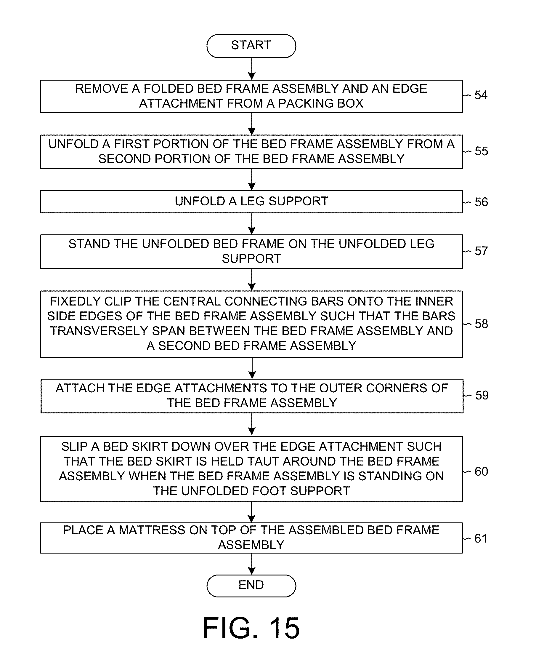
D00013
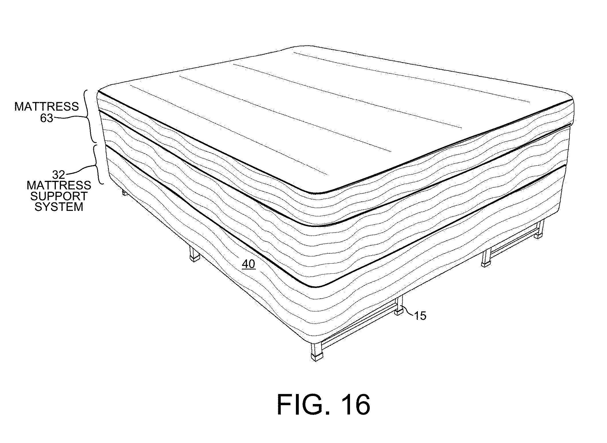
D00014

D00015
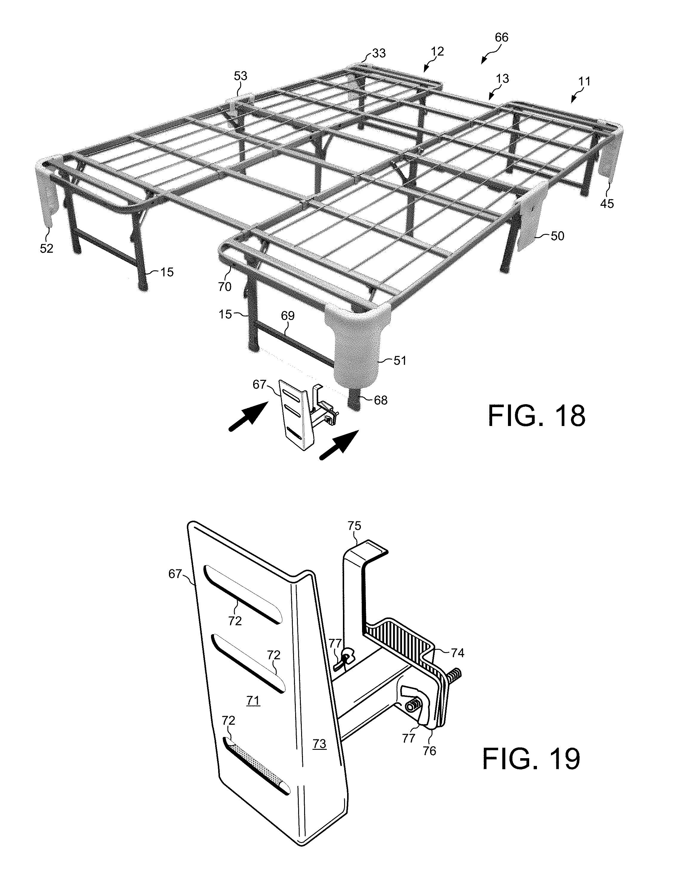
D00016
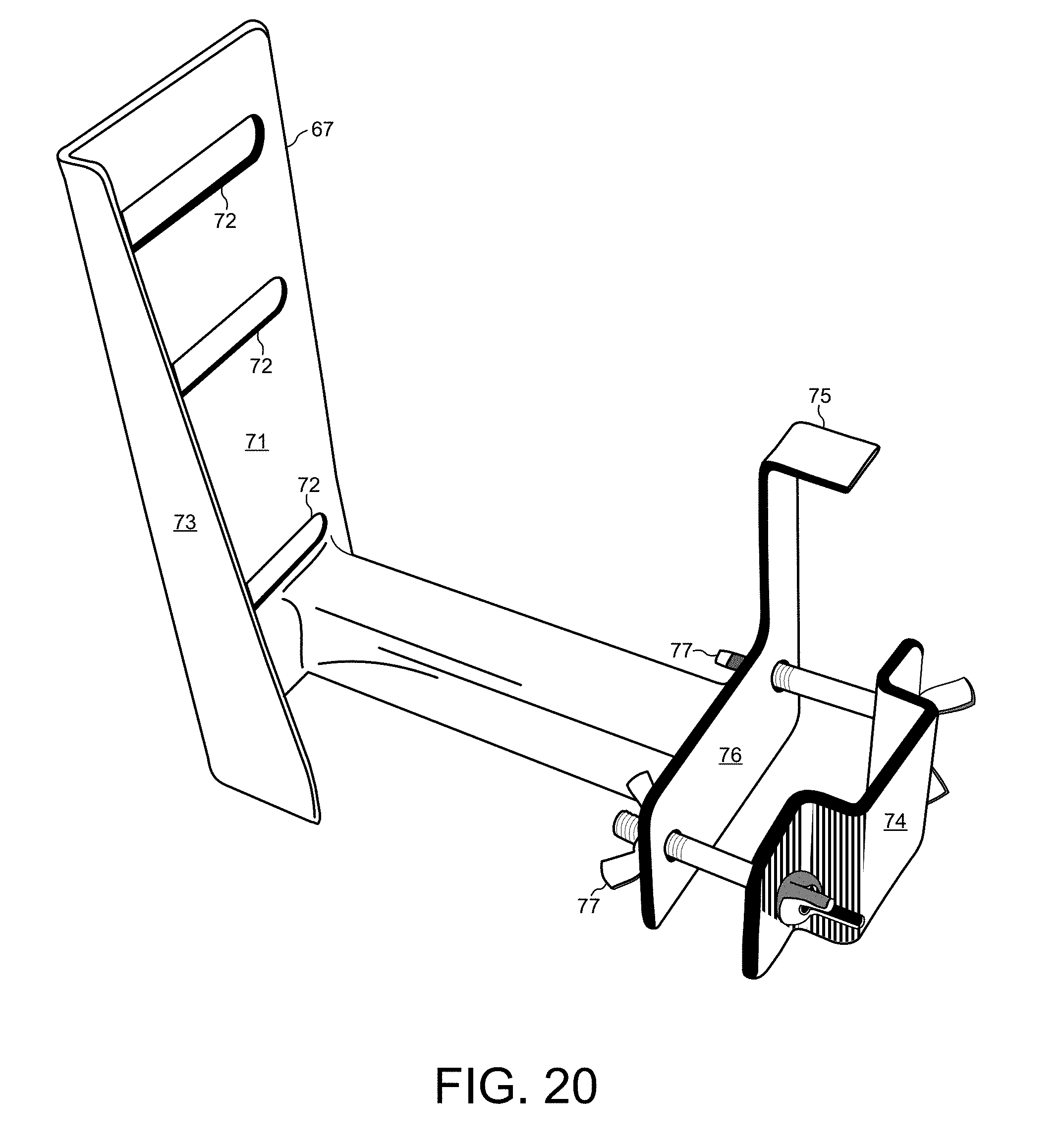
D00017

D00018

D00019

D00020

D00021

D00022

D00023

D00024

D00025

D00026

D00027

D00028

XML
uspto.report is an independent third-party trademark research tool that is not affiliated, endorsed, or sponsored by the United States Patent and Trademark Office (USPTO) or any other governmental organization. The information provided by uspto.report is based on publicly available data at the time of writing and is intended for informational purposes only.
While we strive to provide accurate and up-to-date information, we do not guarantee the accuracy, completeness, reliability, or suitability of the information displayed on this site. The use of this site is at your own risk. Any reliance you place on such information is therefore strictly at your own risk.
All official trademark data, including owner information, should be verified by visiting the official USPTO website at www.uspto.gov. This site is not intended to replace professional legal advice and should not be used as a substitute for consulting with a legal professional who is knowledgeable about trademark law.