Conforming Membrane For Manufacturing Footwear
Kolb; Michael ; et al.
U.S. patent application number 16/196137 was filed with the patent office on 2019-05-23 for conforming membrane for manufacturing footwear. The applicant listed for this patent is NIKE, Inc.. Invention is credited to Lonnie Ballard, Joseph Johnson, Peter Kim, YoungSam Kim, Michael Kolb.
| Application Number | 20190150572 16/196137 |
| Document ID | / |
| Family ID | 65036885 |
| Filed Date | 2019-05-23 |


| United States Patent Application | 20190150572 |
| Kind Code | A1 |
| Kolb; Michael ; et al. | May 23, 2019 |
CONFORMING MEMBRANE FOR MANUFACTURING FOOTWEAR
Abstract
A low-pressure operation conforming membrane for manufacturing an article of footwear includes a perimeter portion having a thickness in a range of 1 to 15 millimeters forming an outer perimeter of the conforming membrane. The conforming membrane also includes a transition portion having a thickness in a range of 1 to 4 millimeters between a first surface and a second surface with the transition portion extending interior to the outer perimeter. The conforming membrane also includes a conforming portion extending from the transition portion in a direction of the second surface and forming a receiving cavity, the conforming portion having a thickness in a range of 1 to 4 millimeters. The perimeter portion, the transition portion, and the conforming portion are a unitary construction comprising a common material composition.
| Inventors: | Kolb; Michael; (Portland, OR) ; Ballard; Lonnie; (Austin, TX) ; Johnson; Joseph; (Austin, TX) ; Kim; Peter; (Saha-gu, KR) ; Kim; YoungSam; (Saha-gu, KR) | ||||||||||
| Applicant: |
|
||||||||||
|---|---|---|---|---|---|---|---|---|---|---|---|
| Family ID: | 65036885 | ||||||||||
| Appl. No.: | 16/196137 | ||||||||||
| Filed: | November 20, 2018 |
Related U.S. Patent Documents
| Application Number | Filing Date | Patent Number | ||
|---|---|---|---|---|
| 62589936 | Nov 22, 2017 | |||
| Current U.S. Class: | 1/1 |
| Current CPC Class: | A43B 9/12 20130101; A43B 13/04 20130101; A43B 5/00 20130101; A43D 2200/50 20130101; A43B 9/00 20130101; A43D 25/10 20130101; B29D 35/0054 20130101; A43D 25/20 20130101; B29D 35/10 20130101 |
| International Class: | A43D 25/10 20060101 A43D025/10; A43B 5/00 20060101 A43B005/00; A43B 13/04 20060101 A43B013/04; A43B 9/12 20060101 A43B009/12; A43D 25/20 20060101 A43D025/20 |
Claims
1. A conforming membrane for aiding in the joining of a first article and a second article, the conforming membrane comprising: a perimeter portion having a thickness in a range of 1 to 15 millimeters forming an outer perimeter of the conforming membrane; a transition portion having a thickness in a range of 1 to 4 millimeters between a first surface and a second surface, wherein the transition portion extends interior to the outer perimeter formed by the perimeter portion; and a conforming portion extending from the transition portion in a direction of the second surface and forming a receiving cavity, the conforming portion having a thickness in a range of 1 to 4 millimeters, wherein the perimeter portion, the transition portion, and the conforming portion are a unitary construction comprising a common material composition.
2. The conforming membrane of claim 1, wherein the first article is a foamed polymer-based article.
3. The conforming membrane of claim 2, wherein the first article is a footwear midsole and the second article is a footwear upper.
4. The conforming membrane of claim 1, wherein the perimeter portion further comprises a first surface and a second surface, both of the perimeter portion first surface and the perimeter portion second surface are positioned on a common side of the transition second surface as the conforming portion.
5. The conforming membrane of claim 1, wherein the perimeter portion has a thickness in a range of 8 to 12 millimeters.
6. The conforming membrane of claim 1, wherein the outer perimeter defines a planar area of 0.08 to 0.15 square meters.
7. The conforming membrane of claim 1, wherein the outer perimeter has a longitudinal length in a range of 400 to 500 millimeters and a transverse length in a range of 200 to 300 millimeters.
8. The conforming membrane of claim 1, wherein the transition portion completely borders the conforming portion and joins the conforming portion and the perimeter portion.
9. The conforming membrane of claim 1, wherein the conforming portion has a durometer in a range of 60 to 61 Asker C.
10. The conforming membrane of claim 1, wherein the conforming portion has a tensile strength in a range of 84 to 90 kg/cm.sup.3.
11. The conforming membrane of claim 1, wherein the conforming portion has an elongation percentage of at least 540 percent elongation prior to failure of the conforming portion.
12. The conforming membrane of claim 1, wherein the transition portion and the conforming portion have a same durometer, tensile strength, or elongation.
13. The conforming membrane of claim 1, wherein the conforming portion extends in a range of 70 to 110 millimeters from the transition portion second surface.
14. The conforming membrane of claim 1, wherein the conforming portion extends in a range of 80 to 100 millimeters from the transition portion second surface.
15. The conforming membrane of claim 1, wherein the receiving cavity has a greater width in a transverse direction at a first half in a longitudinal direction than a width in the transverse direction at a second half in the longitudinal direction.
16. The conforming membrane of claim 1, wherein the conforming portion has a thickness of 2 millimeters.
17. The conforming membrane of claim 1, wherein the material composition comprises natural rubber, silicon dioxide, and calcium carbonate.
18. The conforming membrane of claim 1, wherein the material composition is comprised of 75% to 85% by weight rubber and 5% to 15% silicon dioxide.
19. The conforming membrane of claim 1, wherein the material composition is comprised of 5% to 15% by weight silicon dioxide and 5% to 15% calcium carbonate.
20. The conforming membrane of claim 1, wherein the material composition is comprised of a dispersible silica in a range of 8% to 12% by weight of the material composition.
21. A press having a conforming membrane for aiding in the joining of a first article and a second article, the press comprising: the conforming membrane comprising: (1) a perimeter portion having a thickness in a range of 1 to 15 millimeters forming an outer perimeter of the conforming membrane; (2) a transition portion having a thickness in a range of 1 to 4 millimeters between a first surface and a second surface, wherein the transition portion extends interior to the outer perimeter formed by the perimeter portion; and (3) a conforming portion extending from the transition portion in a direction of the second surface and forming a receiving cavity, the conforming portion having a thickness in a range of 1 to 4 millimeters, wherein the perimeter portion, the transition portion, and the conforming portion are a unitary construction comprising a common material composition; and a pressure source fluidly coupled with the press to control a pressure differential between the transition first surface and the transition second surface of 0.5 to 3.9 bar.
22. A method of manufacturing an article of footwear using a conforming membrane for joining a footwear sole portion and a footwear upper, the method comprising: positioning the footwear upper on a securing element; closing the conforming membrane over the footwear upper on the securing element and the footwear sole portion, with a first surface of the conforming membrane contacting the footwear sole portion and the footwear upper, the conforming membrane comprising: (1) a perimeter portion having a thickness in a range of 5 to 15 millimeters forming an outer perimeter of the conforming membrane; (2) a transition portion having a thickness in a range of 1 to 4 millimeters between a first surface and a second surface, wherein the transition portion extends interior to the outer perimeter formed by the perimeter portion; and (3) a conforming portion extending from the transition portion in a direction of the second surface and forming a receiving cavity, the conforming portion having a thickness in a range of 1 to 4 millimeters, wherein the perimeter portion, the transition portion, and the conforming portion are a unitary construction comprising a common material composition; generating a pressure differential experienced on the first surface of the conforming membrane and an opposite second surface of the conforming membrane, wherein a pressure at the second surface of the conforming membrane is a greater pressure than a pressure at the first surface; and after a predefined time period, reducing the pressure differential.
23. The method of claim 22, wherein the pressure differential is in a range of 0.5 bar to 3.9 bar.
24. The method of claim 22, wherein the predefined time period is at least 25 seconds.
Description
CROSS-REFERENCE TO RELATED APPLICATIONS
[0001] This application claims the benefit of U.S. Provisional Application No. 62/589,936 entitled "Conforming Membrane for Manufacturing Footwear," and filed Nov. 22, 2017. The entirety of the aforementioned application is incorporated by reference herein.
TECHNICAL FIELD
[0002] Directed to a press membrane used in the joining of two articles.
BACKGROUND
[0003] Traditionally an article of footwear may be manufactured by adhering a sole portion with a lasted upper portion. Pressure, temperature, and/or time are adjusted to achieve a bond between the sole and the lasted upper. The application of pressure may be accomplished with a press effective to aid in supplying a compressive force between the sole and the lasted upper as an adhesive or other joining material bonds the sole and the lasted upper.
BRIEF SUMMARY
[0004] Aspects hereof contemplate a conforming membrane for aiding in the joining of a first article and a second article. The conforming membrane includes a perimeter portion having a thickness in a range of 1 to 15 millimeters ("mm") forming an outer perimeter of the conforming membrane. The conforming membrane also includes a transition portion having a thickness in a range of 1 to 4 mm between a first surface and a second surface. The transition portion extends interior to the outer perimeter formed by the perimeter portion. The conforming membrane also includes a conforming portion extending upwardly from the transition portion in a direction of the second surface and forming a receiving cavity. The conforming portion has a thickness in a range of 1 to 4 mm. The perimeter portion, the transition portion, and the conforming portion are a unitary construction comprising a common material composition.
[0005] This summary is provided to enlighten and not limit the scope of methods and systems provided hereafter in complete detail.
DESCRIPTION OF THE DRAWINGS
[0006] The present invention is described in detail herein with reference to the attached drawing figures, wherein:
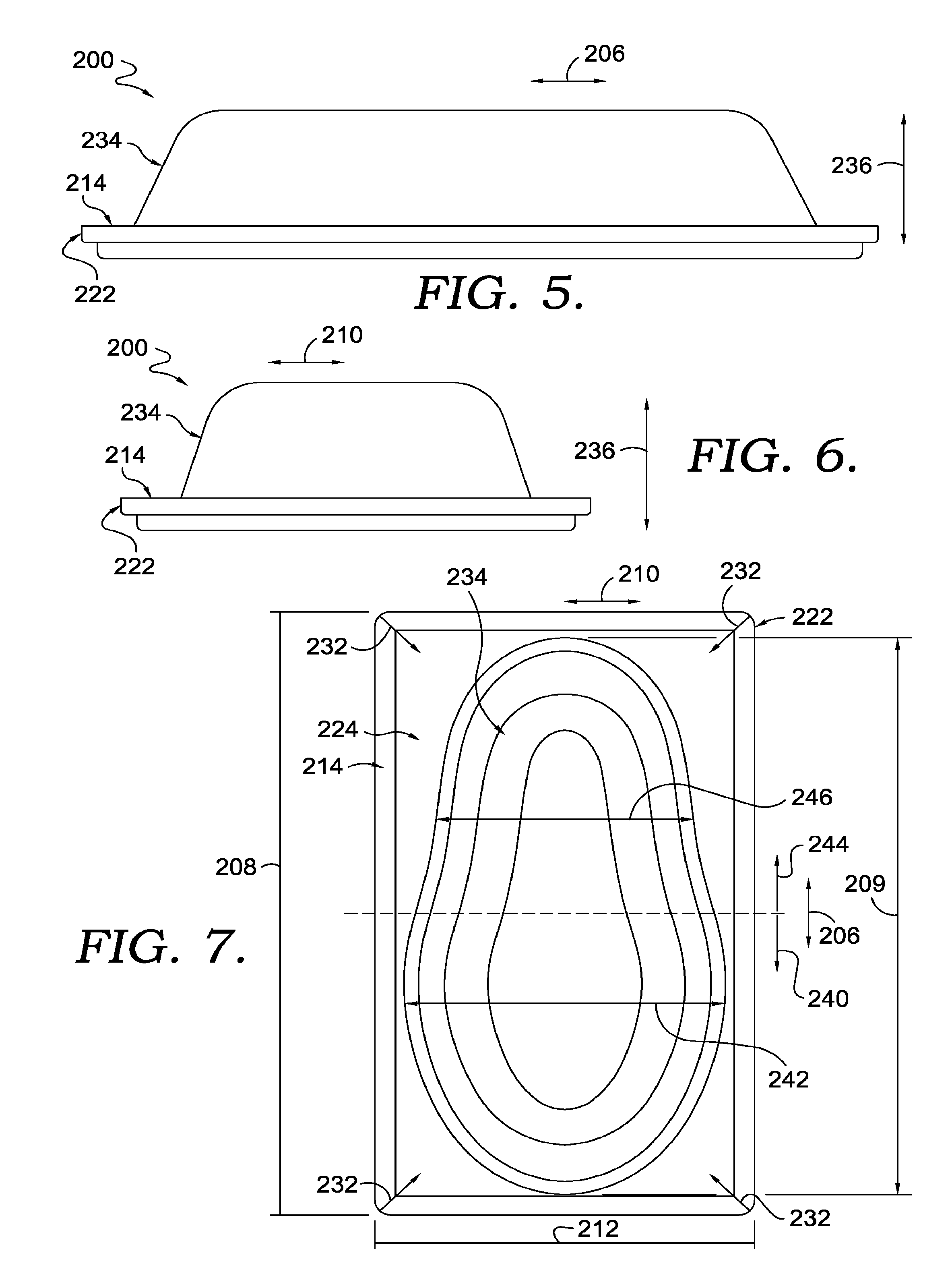
[0007] FIG. 1 depicts a press having a conforming membrane, in accordance with aspects hereof;
[0008] FIG. 2 depicts the press of FIG. 1 in a closed and secured configuration, in accordance with aspects hereof;
[0009] FIG. 3 depicts a cross sectional view of the press along cutline 3-3 of FIG. 2, in accordance with aspects hereof;
[0010] FIG. 4 depicts a perspective view of a conforming membrane, in accordance with aspects hereof;
[0011] FIG. 5 depicts a side view of the conforming membrane of FIG. 4, in accordance with aspects hereof;
[0012] FIG. 6 depicts a front view of the conforming membrane of FIG. 4, in accordance with aspects hereof;
[0013] FIG. 7 depicts a plan view of the conforming membrane of FIG. 4, in accordance with aspects hereof;
[0014] FIG. 8 depicts a cross-sectional view of the conforming membrane along cutline 8-8 of FIG. 4, in accordance with aspects hereof; and
[0015] FIG. 9 depicts a flow chart illustrating an exemplary method of manufacturing an article of footwear with a conforming membrane, in accordance with aspects hereof.
DETAILED DESCRIPTION
[0016] Manufacturing of footwear, such as athletic shoes, is traditionally performed by joining different portions. For example, a footwear upper is a portion of an article of footwear that extends around a wearer's foot to secure the article of footwear to the wearer. The upper may be formed from a variety of materials, such as leather, films, textiles, printed materials, and the like. The upper, in some examples, is a portion of the footwear the includes a securing structure, such as lacing apertures for a lace, an ankle opening for allowing the donning and doffing of a wearer's foot, and other structures. The shape of the upper is determined, in part, at the time it is joined with other portions. In some manufacturing scenarios, a cobblers last, also referred to as a "last" is inserted into the upper (or the upper is formed about the last) causing the upper to acquire a shape of the last. When an upper is placed on a last or otherwise formed around a last, the combination is commonly referred to as a "lasted upper." A lasted upper is an upper having a last providing support and dimensional guidance to the upper during a manufacturing process. As additional portions/components are joined with the lasted upper, the shape of the upper becomes more solidified such that dimensional shape is maintained or at least influenced by the last once the last is removed.
[0017] Another common component of an article of footwear is a sole. A sole may be referred to as a "bottom unit" in some examples. A sole may be a collection of multiple components, such as an outsole, a midsole, and/or an insole. Additional components may also be incorporated, such a cushioning element (e.g., springs), stability elements (e.g., torsion bars), and the like that in combination form a sole. The sole is traditionally a portion that extends between the upper and an underlying ground on to which a wearer of the footwear moves.
[0018] A sole may be formed from a variety of materials. For example, a sole may be formed from leather, felt, textile, and/or polymer-based materials (e.g., natural or synthetic). Different portions of the sole may be formed from different materials. For example, an outsole (e.g., ground contacting portion) may be formed from a rubber (e.g., synthetic or natural) and a midsole portion may be formed from a foamed polymer (e.g., ethylene-vinyl acetate (EVA), polyurethane (PU)). As will be discussed hereinafter, the conforming membrane may be adapted to aid in joining an upper with a sole comprised of a foamed material, such as EVA or PU. Other foamed materials include, but are not limited to low-density polyethylene, polyimide foam, polypropylene foam, polystyrene foam, polyvinyl chloride foam, silicone foam, and the like.
[0019] The upper is traditionally joined with the sole. In some examples the upper and the sole are joined through a stitching operation. In another example, the upper is joined with the sole through a bonding process. The bonding process may be accomplished with welding, fusing, and/or adhesive joining. In an exemplary aspect, an adhesive material (e.g., liquid, paste, film) is applied to at least one of a sole-contacting surface of the upper and/or the upper-contacting surface of the sole. The adhesive may be active or activated to cause a joining (e.g., mechanical bond and/or chemical bond) between the upper and the sole. The joining may be enhanced through an application of pressure, such as applying a force through the upper to the sole and/or applying a force through the sole to the upper. In addition to pressure, it is contemplated that thermal energy (e.g., heat) may be applied to the upper and/or the sole to aid in the joining of the upper and the sole. Further yet, it is contemplated that providing a prescribed time period in which thermal energy and/or pressure is applied to the upper and/or the sole aids in achieving a joining between the upper and the sole. As will be discussed hereinafter, the conforming membrane is effective to provide a sufficient pressure at intended locations to aid in a joining of an upper and a sole, such as through use of an adhesive or other bonding material.
[0020] However, in some traditional joining techniques when applied to joining a compressible sole element (e.g., EVA, PU, or other foamed polymer-based materials) with a lasted upper, the application of pressure causes a permanent, unintended deformation to the compressible sole during the joining processes and therefore deforms the compressible sole in an unintended shape as it is joined to the upper. Stated differently, traditional presses lacking a conformable membrane as provided herein may cause a deformation of a sole portion, wherein the deformation is maintained, at least in part, subsequent to the joining of the upper and the deformed sole. As indicated previously, the construction of an article of footwear may use rely on a successive layering and joining of materials and portions to maintain a shape of the upper as defined by a last once the last is removed after the joining occurs. However, if the lasted upper is joined with a sole that is deformed by a traditional press, once the last is removed after the joining of the sole and the upper, the sole may return toward (completely or partially) the original, non-deformed shape of the sole. This return of the sole to a pre-deformed shape after being joined with the upper may cause a deformation of the upper relative to the shape of the upper as defined by the last. Therefore, a traditional press that applies pressure to a sole to aid in a joining of the sole and an upper may introduce deformation of the sole during the press operation that results in an unintended deformation of the sole and/or the upper subsequent to the press operation.
[0021] It is appreciated that different sole materials may be more susceptible to unintended, permanent deformation. As a result, a traditional press may produce acceptable results for some footwear material combinations. However, as materials advance and application of a greater number of materials (e.g., foamed polymers) are utilized in the components forming the article of footwear, advancement in the press allows for integration of those materials into an article of footwear. For example, soles formed from certain materials produced unsatisfactory bonding (e.g., bonding gaps) when a traditional press is used to join the sole and a lasted upper. When press application from a traditional press lasts over a prescribed time (e.g., 30 seconds, 25 second), the material deforms and causes insufficient bonding. Additionally, a reduced force may be applied to compensate for the non-conforming nature of a traditional press. However, a reduction in force (or time) may result in an insufficient joining (e.g., incomplete bond). Further yet, a traditional press may cosmetically deform one or more portions (e.g., foamed sole portions) as force is applied linearly through the press as opposed in a surrounding manner accomplished by aspects of the conforming membrane provided herein.
[0022] As such, aspects provided herein are directed to a conforming membrane for aiding in the joining of a first article and a second article. A conforming membrane is a membrane that conforms to the lasted upper and the sole to envelope the lasted upper and sole in a compressive force that is normal to a variety of surfaces (e.g., sole ground contacting surface, sole sidewalls, upper medial side, upper, lateral side, upper heel end, upper, toe box). This multi-directional compressive force provided by a conforming membrane secures the sole and lasted upper for a bonding/joining process without deforming a foamed material, such as a sole portion. This is contrary to a traditional press that fails to sufficiently conform around the lasted upper and the sole and/or that relies on a higher pressure to cause the conformance of the press material. A traditional press instead concentrates pressure through the sole in a more linear manner as opposed to the multi-directional compressive force provided by a conforming membrane. Additionally, a traditional press that may have a "conforming" membrane may only be "conforming" when under significantly higher pressure than that provided in connection with aspects hereof.
[0023] The conforming membrane includes a perimeter portion having a thickness in a range of 1 to 15 millimeters ("mm") forming an outer perimeter of the conforming membrane. In some aspects, the perimeter portion has a thickness in a range of 5 to 15 mm, 8 to 12 mm, or about 10 mm in another example. The conforming membrane also includes a transition portion having a thickness in a range of 1 to 4 mm between a first surface and a second surface. The transition portion extends interior to the outer perimeter formed by the perimeter portion. The conforming membrane also includes a conforming portion extending from the transition portion in a direction of the second surface and forming a receiving cavity. The conforming portion has a thickness in a range of 1 to 4 mm. The perimeter portion, conforming portion and the transition portion may have a same thickness, or a different thickness. The conforming portion and the transition portion may have a same thickness, or a different thickness. The perimeter portion, the transition portion, and the conforming portion are a unitary construction comprising a common material composition.
[0024] Further, aspects contemplate implementing a conforming membrane with a manufacturing of an article of footwear such that a method of manufacturing an article of footwear using a conforming membrane for joining a footwear sole portion and a footwear upper includes positioning the footwear upper on a securing element (e.g., a press support). The method includes closing the conforming membrane over the footwear upper on the securing element and the footwear sole portion. In this example a first surface of the conforming membrane contacts the footwear sole portion and the footwear upper. The conforming membrane may be the conforming membrane in the preceding paragraph or any derivation provided herein. The method continues with reducing the pressure differential after a predefined period of time (e.g., greater than 25 seconds, greater than 30 seconds, greater than 35 seconds). The pressure differential may be in a range of 0.5 to 3.9 bar (i.e., 50 kilopascals to 390 kilopascals), in an exemplary aspect.
[0025] The conforming membrane and contemplated method of use provides a tool to join an upper and a sole with reduced deformation of the upper and/or sole relative to a traditional press (e.g., membrane press). In some examples, characteristics of the conforming membrane, such as thickness and material composition allow the membrane to conform around a sole portion and an upper portion to apply pressure (and heat in some examples) across multiple surfaces (e.g., toebox, heel counter, upper medial side, upper lateral side, across the sole-to-upper transition (e.g., biteline), sidewalls of the sole) during a joining of the upper portion and the sole portion at lower pressure. This is in contrast to a thicker or different material composition of a traditional press membrane that applies a more linear force that extends linearly through the sole and/or upper (as opposed to around from multiple directions) at higher pressures (e.g., 4 bar or greater) causing a deformation of the sole and/or upper during a press operation.
[0026] Turing to the figures in general and FIG. 1 specifically, which depicts a press 100 having a lasted upper 252 and sole 250 secured to a securing element 102, in accordance with aspects hereof. At a high level, the press 100 is adapted to maintain an upper and sole in a relative position to each other while being joined. For example, an adhesive may be applied (e.g., sprayed, painted, rolled, laid, printed) to the sole, the upper, or a combination of the sole and upper. Additionally, it is contemplated that the upper 252 and/or the sole 250 may be formed from one or more materials that join under pressure and/or heat to the other component (e.g., hot-melt adhesive, meltable polymer). The sole 250 and the upper 252 then have a pressure applied by a conforming membrane 200 that is housed in a membrane vessel 116 (e.g., a lid). As the membrane vessel 116 is positioned over the sole 250 and the upper 252, the combination of components are at least partially received in a receiving cavity 238 of the conforming membrane 200. The receiving cavity is an intentional deformation (e.g., molded or otherwise formed) from a planar configuration of the conforming membrane 200 to allow for multiple surfaces (e.g., medial side, lateral side, toe box at a toe end 254, a heel counter at a heel end 256, biteline) of the to-be-formed footwear to be contacted by the conforming membrane 200 during a press operation. The membrane vessel 116 may be secured in a closed, operational configuration to the press 100 by a membrane securement 114, such as a releasable latching mechanism. The membrane securement 114 is effective to maintain the membrane vessel 116 and associated conforming membrane 200 in a position relative to the article of footwear to which pressure will be applied.
[0027] With respect to pressure, it is contemplated that pressure may be applied to the sole 250 and the upper 252 in one or more ways by the press 100. For example, the securing element 102 may be effective to apply a linear force, such as through a pneumatic cylinder, a linear actuator, and the like. This linear force is transferred through a last 120 (as best seen in FIG. 3) to the upper 252 and the sole 250 where resistance to the linear force is met by the conforming membrane 200 contacting the upper 252 and/or the sole 250. Additionally or alternatively, it is contemplated that the securing element 102 is effective to adjust a position of the upper 252 and the sole 250 within the receiving cavity 238. For example, the securing element 102 may raise or lower (with reference to the vertical position the press 100 of FIG. 1 as depicted) the footwear components based on a intended pressure, component size, component shape, and the like. The securing element 102, in some aspects may be static and un-moveable.
[0028] Pressure may alternatively or additionally be generated by the press 100 through pressurization of the conforming membrane 200. In an exemplary aspect also depicted in FIG. 3, a positive pressure relative to ambient pressure may be introduced to a volume enclosed by the membrane vessel 116 and the conforming membrane 200. The increased pressure forms a pressure differential on opposing surfaces of the conforming membrane 200. The pressure differential cause the conforming membrane 200 to conform around the upper 252 and the sole 250 as the conforming membrane 200 deforms under the pressure differential. It is this deformation that causes the conforming membrane 200 to wrap around portions of the upper 252 and the sole 250 generating a pressure that maintains the upper 252 and the sole 250 in fixed relative positions during a joining operation. Depending on the differential in pressure, a sufficient pressure may be exerted on the upper 252 and the sole 250 to aid in joining (e.g., bonding through adhesive curing) of those components. Exemplary pressure differentials include 0.5 bar up to 3.9 bar relative to ambient pressures. Above 3.9 bar, in an exemplary aspect, the conforming membrane may mechanically fail after a number of press cycles or the article being pressed may unintentionally, permanently deform during the press operation. While pressure differentials above and below 0.5 bar to 3.9 bar are contemplated, aspects herein implement pressure differentials in the provided range to reduce unintentional deformation of the pressed article. Less conforming membranes of traditional presses may operate with a pressure differential at or above 4 bar in order to conform and comply with the pressed article. This increased pressure may allow a tradition press membrane to conform, but it can damage or otherwise insert unintended deformations into a pressed article, such as a portion of an article of footwear. Therefore, implementations of the conforming membrane provided herein operate at a lower pressure differential to achieve a conformance of the membrane to the pressed article than that of a traditional press membrane. In additional aspect, the pressure differential expressed in bar pressure is in a range of 1 to 3, 1 to 2, 1 to 1.5, 1 to 1.3, 1 to 1.2, 1.1 to 1.4, and/or 1.25 to 1.35 bar. The various pressure differential windows provide flexibility based on materials to be bonded, press times, degree of conformance of the membrane, and the like. Therefore, based on the factors contemplated herein, various pressure differential ranges may be applied to achieve a bonding of footwear component while minimizing unintentional, permanent deformation of the footwear components.
[0029] FIG. 2 depicts the press 100 having the membrane vessel 116 in a closed and secured configuration, in accordance with aspects hereof. The closed configuration is a configuration that allows the press 100 to effectively apply pressure to footwear components during a joining operation. Also depicted are input mechanisms for the press 100. A time control 110, a pressure control 112, and a temperature control 118 are depicted. The input mechanisms allow a user to adjust the namesake parameters (e.g., time, temperature, pressure). However, it is contemplated that one or more of the input mechanisms are omitted or altered in exemplary aspects. For example, computer instructions may be communicated to the press from a controller that controls the time, pressure, and/or time applied to a specific (or general) component. Further, it is contemplated that one or more of time, temperature, or pressure may not be adjusted in some examples.
[0030] FIG. 3 depicts a cross-sectional view along cutline 3-3 of FIG. 2, in accordance with aspects hereof. A toe-to-heel perspective is provided illustrating the securing element 102 maintaining the last 120 in a position that allows the upper 252 and the upper 250 to be contacted by the conforming membrane 200. FIG. 3 depicts the conforming membrane 200 during a pressure differential causing the conforming membrane 200 to conform to the lasted upper 252 and sole 250. A pressure source 106 provides an exemplary source of the pressure to form the pressure difference. The pressure source may provide a compressible or non-compressible material (e.g., gas or liquid) into a membrane chamber 104 from an exterior source (e.g., tank, pump, and compressor). The membrane chamber 104 is enclosed and formed by the membrane vessel 116 and the conforming membrane 200. The membrane chamber 104 is effective to receive a pressurizing material (e.g., pressurized air) and provide a volume for the pressurizing material to surround and exert force on portions of the conforming membrane 200 from within the membrane chamber 104. Pressure may be controlled with one or mechanisms, such as a regulator and the like. Unlike a traditional press membrane that operates at 4 bar and above, aspects herein contemplate operating at lower pressures (e.g., 0.5 to 3.9 bar), therefore a traditional macro-level control of pressure may result in unintentional permanent deformation of a pressed article as the macro-level control (e.g., analog regulator with 1 bar or greater tolerances) has a large operating tolerance for pressure. This large tolerance could result in a greater pressure differential at the conforming membrane provided herein causing an unintended, permanent deformation of the pressed article. As such, this macro-level control of pressure for a pressure differential at or above 4 bar is ineffective to control a pressure differential having a range of 0.5 to 3.9 bar, in exemplary aspect. Further to this, a macro-level control of pressure for a pressure differential at or above 4 bar is ineffective to control a pressure differential having a range of 1 to 2 bar, in exemplary aspect. Therefore, aspects hereof contemplate upgrading the pressure control mechanism to a micro-level control (e.g., a digital regulator with 0.9 bar or less tolerance) that is able to maintain a pressure differential within a tighter tolerance range than that of a pressure mechanism of a traditional press. Increase pressure tolerance control may provide greater durability of the conforming membrane (e.g., reduces over pressurization potential) and allows for more consistent operation at lower pressures provided herein. Stated differently, as aspects herein contemplate operating at a lower pressure differential than a standard press, greater control of the pressure differential increases results from the conforming membrane press, in exemplary aspects hereof.
[0031] Also depicted in FIG. 3 is an optional heating source 108. The heating source 108 may be a resistive heating element, an infrared heating element, an induction heating element, and the like. Alternatively, it is contemplated that the pressurized material may be heated externally to the membrane chamber 104 and introduced at an elevated (or reduced) temperature relative to ambient conditions, in some aspects. Heat may be used to activate, melt, or cure one or more materials, such as a bonding material. For example, a low-melt adhesive that has a deformation temperature (e.g., melting temperature) that is lower than the membrane, the upper, and the sole may be positioned between the upper and the sole. Prior to conforming or subsequent to conforming the conforming membrane 200 around portions of the sole and the upper, heat may be generated or applied to activate the low-melt adhesive. The thermal energy may then be reduced while maintaining pressure from the conforming membrane 200 until the low-melt adhesive (or any bonding material) has a sufficient bond between the components. It is contemplated that the heating source 108 is optional and may be omitted altogether in aspects contemplated herein.
[0032] FIG. 3 introduces three regions of the conforming membrane 200. A perimeter portion 214, a transition portion 224, and a conforming portion 234 that will be discussed in greater detail in FIGS. 4-8 hereinafter. As depicted in FIG. 3, the conforming membrane 200 wraps around and surrounds portions of the upper 252 and the sole 250 from multiple directions on multiple surfaces. It is this conformance to multiple surfaces and components that allows the conforming membrane 200 to effectively join the upper 252 and the sole 250.
[0033] As previously provided, a less-conforming (or non-conforming) membrane of a traditional press could instead permanently deform the sole 250, such as compressing a foam material, during a pressing operation as it fails to sufficient conform and therefore applies a more focused and unidirectional pressure to the sole. The permanent deformation that result in an unacceptable pressed part may also result from operating a traditional press membrane at a higher pressure (e.g., 4 bar and higher) to achieve a level of conformance of the traditional press membrane to the pressed component. The higher pressure differential used on a traditional press compensates for a less conforming membrane material, which translates to a potentially damaging force being applied to the pressed article. This unintentional deformation may be further exaggerated if thermal energy is applied to the process to activate or cure a bonding material. The increased thermal energy may cause the material forming the sole (e.g., PU, EVA) to become more compliant and therefore more susceptible to unintentional deformation under a pressure from a press. As such, having a compliant membrane that surround from multiple directions the various surfaces of the components to be joined, the pressure of the press is applied across a greater surface area in a greater number of degrees of direction allowing the same materials that may unintentionally deform under a traditional membrane to be effectively joined with the conforming membrane 200.
[0034] FIG. 4 depicts a perspective view of the conforming membrane 200, in accordance with aspects hereof. A longitudinal direction 206 and a transverse direction 210 are generally illustrated for reference purposes. As it is contemplated that the conforming membrane is used in connection with articles of footwear, the conforming membrane has a receiving cavity that is formed in a general shape of an article of footwear portion intended to be received. This general and intentional deformation limits creases or other membrane deviations when place under a pressure differential to form a smooth conformance to the underlying footwear components. Stated differently, in some examples the receiving cavity has a shape similar to the article to which it is intended to conform under a pressure differential. This coordination between the receiving cavity shape and the footwear article allows for a more uniform conformance by the membrane to the to-be-joined components under a pressure differential.
[0035] The perimeter portion 214, the transition portion 224, and the conforming portion 234 of the conforming membrane 200 are depicted in FIG. 4. Additionally, an outer perimeter 222 is depicted as forming an outermost portion of the conforming membrane 200. A conforming membrane second surface 204 is also depicted. The conforming membrane second surface 204 is opposite a conforming membrane first surface 202, as best seen in FIG. 8.
[0036] FIG. 5 depicts a side view of the conforming membrane 200, in accordance with aspects hereof. A z-direction 236 is illustrated. The z-direction 236 is a direction in which the conforming portion 234 extends from the transition portion 224. FIG. 6 depicts a front view of the conforming membrane 200, in accordance with aspects hereof.
[0037] FIG. 7 depicts a plan view of the conforming membrane 200 of FIGS. 4-6, in accordance with aspects hereof. Several exemplary positional elements are depicted in FIG. 7. For example, a receiving cavity first half 240 and a receiving cavity second half 244 are depicted along the longitudinal direction 206. Additionally a series of arrow indicators 232 are depicted to illustrate an "internal" direction in the plan view plane of the conforming membrane 200 relative to the outer perimeter 222.
[0038] The conforming portion 234 includes the receiving cavity 238. The receiving cavity first half 240 has a maximum width 242 and the receiving cavity second half 244 has an exemplary width 246. The width of the receiving cavity portions are measured in the transverse direction 210. As the receiving cavity is shaped to conform to an article of footwear, the maximum width 242 of the receiving cavity first half 240 is greater than any width of the receiving cavity second half 244 (e.g., width 246), in this example. It is contemplated that the receiving cavity may have any shape depending on the article to be compressed by the conforming membrane.
[0039] The conforming membrane 200 has a length 208 in the longitudinal direction 206 measured from the outer perimeter 222. The conforming membrane 200 has a width 212 in the transverse direction 210 measured from the outer perimeter 222. The length 208 is contemplated to be in a range of 400 to 500 mm, in an exemplary aspect. The length 208 is contemplated to be in a range of 425 to 475 mm, in an exemplary aspect. The length 208 is contemplated to be in a range of 450 to 465 mm, in an exemplary aspect. The width 212 is contemplated to be in a range of 200 to 300 mm, in an exemplary aspect. The width 212 is contemplated to be in a range of 210 to 250 mm, in an exemplary aspect. The width 212 is contemplated to be in a range of 220 to 240 mm, in an exemplary aspect. In view of the provided exemplary ranges, it is contemplated that the outer perimeter 222 may define a planar surface area of 0.08 to 0.15 square meters. This area allows for sufficient conforming membrane material to conform to the components to be compressed while minimizing material and weight associated with the conforming membrane 200. The length and width may depend on a style, size, or type of article to be compressed by the conforming membrane 200.
[0040] Additionally, the conforming portion 234 has a maximum length 209. The length 209 is contemplated to be in a range of 350 to 450 mm, in an exemplary aspect. The length 209 is contemplated to be in a range of 375 to 425 mm, in an exemplary aspect. The length 209 is contemplated to be in a range of 395 to 415 mm, in an exemplary aspect. The maximum width 242 is contemplated to be in a range of 150 to 250 mm, in an exemplary aspect. The maximum width 242 is contemplated to be in a range of 175 to 225 mm, in an exemplary aspect. The maximum width 242 is contemplated to be in a range of 190 to 210 mm, in an exemplary aspect. The receiving cavity length 209 and width 242 are selected, in an exemplary aspect to provide a sufficiently sized receiving cavity for the components to be received while limiting excess conforming membrane material. For example, the length and width of the receiving cavity 238 may be 1 to 10% greater than similar measurements of the components to be received therein to achieve easy insertion and extraction without introducing unintentional deformations as the membrane conforms to the underlying components.
[0041] FIG. 8 depicts a cross section along cutline 8-8 of the conforming membrane 200 from FIG. 4, in accordance with aspects hereof. The perimeter portion 214 has a perimeter portion first surface 218 and a perimeter portion second surface 220 with a thickness 216 defined there between. The transition portion 224 has a transition portion first surface 228 and a transition portion second surface 230 and a thickness 226 defined there between. The conforming portion 234 has a conforming portion first surface 235 and a conforming portion second surface 237 and a thickness 248 there between.
[0042] Thickness of the conforming portion 234, the transition portion 224, and the perimeter portion 214 affect the ability of the conforming membrane 200 to conform to an article under a pressure differential. Historical membranes in a historical press may have a greater thickness in the various portions. The greater thickness traditionally may have been implemented to allow materials forming the traditional membranes to have a greater longevity during industrial application. However, the conforming membrane 200 may be operated at different conditions (e.g., temperature, pressure, time) as a result of the more compliant parts to be joined and/or formed from different materials and therefore can deviate to a thinner (e.g., less) thickness) than a traditional membrane. In some examples, as a thickness in a portion of the conforming membrane reduces, the conforming membrane may become more compliant and able to conform to the underlying article. However, if the thickness is reduced too much, the conforming membrane may suffer from fatigue and failure for practical industrial application. As such, in an exemplary aspect ranges of various thicknesses are contemplated to provide a sufficient compliance to the conforming membrane 200 while achieving sufficient service life.
[0043] The perimeter portion thickness 216 is contemplated to be in a range of 1 to 15 mm, in accordance with aspects hereof. The perimeter portion thickness 216 is contemplated to be in a range of 5 to 15 mm, in accordance with aspects hereof. The perimeter portion thickness 216 is contemplated to be in a range of 8 to 12 mm, in accordance with aspects hereof. The perimeter portion thickness 216 is contemplated to be about 10 mm, in accordance with aspects hereof. The transition portion thickness 226 is contemplated to be in a range of 1 to 4 mm, in accordance with aspects hereof. The transition portion thickness 226 is contemplated to be about 2 mm, in accordance with aspects hereof. The conforming portion thickness 248 is contemplated to be in a range of 1 to 4 mm, in accordance with aspects hereof. The conforming portion thickness 248 is contemplated to be about 2 mm, in accordance with aspects hereof. The perimeter portion thickness 216, the transition portion thickness 226, and the conforming portion thickness 248 may be the same in exemplary aspects. The perimeter portion thickness 216, the transition portion thickness 226, and/or the conforming portion thickness 248 may be different in exemplary aspects.
[0044] In an exemplary aspect, the conforming portion 234 and the transition portion 224 are contemplated to have a similar thickness. This common thickness may allow the transition portion 224 to similarly comply as the conforming portion 234 during a pressure differential preventing areas of greater elongation in the conforming portion 234. In some examples, the transition portion 224 completely borders or encircles the conforming portion 234. Stated differently, the transition portion 224 provides functional transition between the perimeter portion 214 and the conforming portion 234 that extends in a z-direction. By surrounding the conforming portion 234, the transition portion 224 allows the conforming portion 234 to conform to a received article even at an outermost portion of the conforming portion 234.
[0045] The perimeter portion thickness 216 may be greater than the transition thickness 226, in an exemplary aspect, to increase longevity, service life, and concentration of compressive energy around a received article. As thickness of the conforming membrane affects functional characteristics (e.g., elongation), the conforming membrane 200 is more susceptible to deformation with a pressure differential at locations having a smaller thickness (i.e., thinner regions). Therefore, by reducing the thickness of the conforming membrane 200 at the receiving cavity 238 and proximate the article to be received, the conforming membrane 200 conforms more around the received article than at the perimeter portion 214 having a greater thickness. As the perimeter portion 214 has a greater thickness resulting in fewer conformances, the perimeter portion 214 may be less susceptible to fatigue failure from repeated conformance during pressure differential cycles, in an exemplary aspect.
[0046] FIG. 8 depicts an extension height 258 of the conforming portion 234 from the transition portion 224. The height 258 is in a range of 70 to 110 mm, in accordance with aspects hereof. The height 258 is in a range of 80 to 100 mm, in accordance with aspects hereof. The height 258 is about (e.g., within 10%) of 90 mm, in accordance with aspects hereof. A traditional membrane may have a height that is significantly less than those of the conforming membrane 200. In those examples, the lesser height prohibits the membrane from surrounding multiple surfaces of the article and therefore a deformation-susceptible material (e.g., foamed polymer of a sole) may deform under a directional compression of a traditional membrane. The conforming membrane 200 having a greater height than a traditional membrane is allowed to instead surround a sole portion and at least part of an upper to envelope the article in a unitary pressure rather than a directional pressure (e.g., linearly from the membrane toward a securing element).
[0047] In an exemplary aspect, the perimeter portion first surface 218 and the perimeter portion second surface 220 are positioned above the transition portion second surface 230. Further, it is contemplated in an exemplary aspect that the perimeter portion first surface 218 and the perimeter portion second surface 220 are positioned on a common side of the transition portion second surface 230 as the conforming portion 234 extends (e.g., upwardly in FIG. 8). This offsetting between the perimeter portion 214 and the transition portion 224 allows for greater conformance of the conforming membrane 200 about the received article in an inner direction relative to the outer perimeter 222. Stated differently, the offsetting in vertical placement of the perimeter portion 214 and the transition portion 224 allows for a transfer of vertical displacement for horizontal conformance as a pressure differential is applied, in an exemplary aspect.
[0048] The conforming membrane 200 is formed from a conforming material. In one aspect, the conforming membrane is formed from material composition comprising a rubber (e.g., natural rubber), silicon dioxide (i.e., silica), and calcium carbonate. Additional materials may be included in the composition. In an exemplary aspect, the material composition of the conforming membrane 200 is comprised of 75% to 85% by weight rubber and 5% to 15% by weight silicon dioxide. In an exemplary aspect, the material composition of the conforming membrane 200 is comprised of 5% to 15% by weight calcium carbonate and 5% to 15% by weight silicon dioxide. In an exemplary aspect, the material composition of the conforming membrane 200 is comprised of 8% to 12% by weight of a dispersible silica. In an exemplary aspect, the material composition of the conforming membrane 200 is comprised of 75% to 85% by volume rubber and 5% to 15% by volume silicon dioxide. In an exemplary aspect, the material composition of the conforming membrane 200 is comprised of 5% to 15% by volume calcium carbonate and 5% to 15% by volume silicon dioxide. In an exemplary aspect, the material composition of the conforming membrane 200 is comprised of 8% to 12% by volume of a dispersible silica. Percentage of composition is determined prior to combination, in exemplary aspects.
[0049] It is contemplated that the conforming membrane is a unitary material extending between two or more portions. For example, it is contemplated that the conforming portion 234 and the transition portion 224 are formed from a common material such that the composition of material forming the portions is homogenous. Similarly, it is contemplated that the perimeter portion 214, the transition portion 224, and the conforming portion 234 are unitary and formed from a common material. A unitary construction is a single entity having a uniform material composition. For example, two or more portions of the conforming membrane may be produced simultaneously. In an example, a molding operation may be performed that forms the two or more portions in combination. In an alternative manufacturing process, it is contemplated that a common material is subtractively formed (e.g., milled) to form the conforming membrane. In this example, the portions formed from the subtractive method are unitary as they all begin with a common source material without subsequent joining.
[0050] Functional characteristics of the conforming membrane 200 may be quantified to provide a range of a conforming membrane suitable for exemplary aspects hereof. For example, the conforming membrane 200, at least in the conforming portion 234, may have a hardness of 60-61 Asker C as measured on an ASKER Type C Durometer, in accordance with aspects hereof. The conforming membrane 200, at least in the conforming portion 234, may have a maximum tensile strength in a range of 84 to 90 kg/cm.sup.3 range, in accordance with aspects hereof. The maximum tensile strength may be tested using a test such as the ASTM D638-14 testing protocol. The conforming membrane 200, at least in the conforming portion 234, may have a maximum elongation until destruction of at least 540%, in accordance with aspects hereof. The maximum elongation may be tested using a test such as the ASTM D-638 testing protocol.
[0051] The material composition and resulting functional characteristics of the conforming membrane 200 provide a suitable material for use as a membrane to join two or more footwear portions without deforming or damaging a foamed polymer component, such as an EVA or PU midsole element, in an exemplary aspect. The material composition provided herein for the conforming membrane 200 is contemplated to save in labor, cost, and/or material. For example, operating at a lower pressure than a traditional membrane press to achieve conformance of the membrane to the underlying pressed article reduces subsequent interventions to correct unintentional deformations of the pressed materials. Additionally, with a conforming membrane that operates at a lower pressure, energy savings are achieved by the use of lower pressure needs. Additionally, operating a conforming membrane at a lower pressure with the contemplated material composition allows for a thinner membrane that reduces material use for forming the membrane, which reduces material costs, in an exemplary aspect.
[0052] Turning to FIG. 9 illustrating a method 900 of manufacturing an article of footwear using a conforming membrane for joining a footwear sole portion and a footwear upper, in accordance with aspects hereof. At a block 902 a footwear upper is positioned on a securing element. The footwear upper may be a lasted upper where the last is secured to the securing element. At a block 904, the conforming membrane, such as the conforming membrane 200 provided herein, is closed on the footwear upper and a footwear sole portion. In this example, the footwear upper and the footwear sole are positioned in an intended relative position to each other. An adhesive or other bonding material may be applied prior to joining the two components.
[0053] At a block 906, a pressure differential is generated between opposing surfaces of the conforming membrane. For example, a pressurized fluid (e.g., gas or liquid) may be inserted into a membrane cavity where the conforming membrane is more compliant than the other materials forming the membrane cavity. As a result, the membrane cavity deforms and conforms around the lasted upper and sole creating a compressive force to secure the sole with the lasted upper. The compressive force is applied to both the upper and the sole at multiple surfaces inclusive of a junction between the sole and the upper. This enveloping compression maintains the sole in a defined location relative to the upper during a joining operation.
[0054] At a block 908, the pressure differential is reduced after a predefined period of time. This tie period may be 20 seconds, 25 seconds, 30 seconds, or any time appropriate to allow for the joining of the sole with the upper.
[0055] Other steps contemplated, but not illustrated in FIG. 9 include, but are not limited to, application of thermal energy, extraction of thermal energy (e.g., cooling), and adjusting a time, pressure, and/or temperature.
[0056] The following is a non-limiting exemplary listing of parts provided in the figures. [0057] Press--100 [0058] Securing element--102 [0059] Membrane chamber--104 [0060] Pressure source--106 [0061] Heating source--108 [0062] Time control--110 [0063] Pressure control--112 [0064] Membrane securement--114 [0065] Membrane vessel--116 [0066] Temperature control--118 [0067] Conforming membrane--200 [0068] Conforming membrane first surface--202 [0069] Conforming membrane second surface--204 [0070] Longitudinal direction--206 [0071] Longitudinal length--208 [0072] Receiving cavity length 209 [0073] Transverse direction--210 [0074] Transverse width--212 [0075] Perimeter portion--214 [0076] Perimeter portion thickness--216 [0077] Perimeter portion first surface--218 [0078] Perimeter portion second surface--220 [0079] Outer perimeter--222 [0080] Transition portion--224 [0081] Transition portion thickness--226 [0082] Transition portion first surface--228 [0083] Transition portion second surface--230 [0084] Arrow indicators of an interior direction--232 [0085] Conforming portion--234 [0086] Conforming portion first surface--235 [0087] Z-direction--236 [0088] Conforming portion second surface--237 [0089] Receiving cavity--238 [0090] Receiving cavity first half--240 [0091] Receiving cavity first half maximum width--242 [0092] Receiving cavity second half--244 [0093] Receiving cavity second half width--246 [0094] Conforming portion thickness--248 [0095] Sole--250 [0096] Upper--252 [0097] Toe end--254 [0098] Heel end--256
[0099] Many different arrangements of the various components depicted, as well as components not shown, are possible without departing from the spirit and scope of the present disclosure. Embodiments of the present disclosure have been described with the intent to be illustrative rather than restrictive. Alternative embodiments will become apparent to those skilled in the art that do not depart from its scope. A skilled artisan may develop alternative means of implementing the aforementioned improvements without departing from the scope of the present disclosure.
[0100] It will be understood that certain features and subcombinations are of utility and may be employed without reference to other features and subcombinations and are contemplated within the scope of the claims. Not all steps listed in the various figures need be carried out in the specific order described.
* * * * *
D00000
D00001
D00002
D00003
D00004
XML
uspto.report is an independent third-party trademark research tool that is not affiliated, endorsed, or sponsored by the United States Patent and Trademark Office (USPTO) or any other governmental organization. The information provided by uspto.report is based on publicly available data at the time of writing and is intended for informational purposes only.
While we strive to provide accurate and up-to-date information, we do not guarantee the accuracy, completeness, reliability, or suitability of the information displayed on this site. The use of this site is at your own risk. Any reliance you place on such information is therefore strictly at your own risk.
All official trademark data, including owner information, should be verified by visiting the official USPTO website at www.uspto.gov. This site is not intended to replace professional legal advice and should not be used as a substitute for consulting with a legal professional who is knowledgeable about trademark law.