Helmet Having A Temperature Control Mechanism For Controlling The Temperature
ZOREF; David
U.S. patent application number 16/198200 was filed with the patent office on 2019-05-23 for helmet having a temperature control mechanism for controlling the temperature. This patent application is currently assigned to David ZOREF. The applicant listed for this patent is David ZOREF. Invention is credited to David ZOREF.
| Application Number | 20190150550 16/198200 |
| Document ID | / |
| Family ID | 66534744 |
| Filed Date | 2019-05-23 |


View All Diagrams
| United States Patent Application | 20190150550 |
| Kind Code | A1 |
| ZOREF; David | May 23, 2019 |
HELMET HAVING A TEMPERATURE CONTROL MECHANISM FOR CONTROLLING THE TEMPERATURE
Abstract
A helmet adapted to control the temperature within the helmet is disclosed. The helmet contains therein a pipe designed to drive therein a cooled or heated liquid. The pipe is positioned with the helmet such that the pipe is in partial contact with the user's head body part when wearing the helmet.
| Inventors: | ZOREF; David; (Kfar-Saba, IL) | ||||||||||
| Applicant: |
|
||||||||||
|---|---|---|---|---|---|---|---|---|---|---|---|
| Assignee: | ZOREF; David Kfar-Saba IL |
||||||||||
| Family ID: | 66534744 | ||||||||||
| Appl. No.: | 16/198200 | ||||||||||
| Filed: | November 21, 2018 |
Related U.S. Patent Documents
| Application Number | Filing Date | Patent Number | ||
|---|---|---|---|---|
| 62590298 | Nov 23, 2017 | |||
| Current U.S. Class: | 1/1 |
| Current CPC Class: | F25B 21/04 20130101; F25B 2321/0252 20130101; A42B 3/125 20130101; A42B 3/285 20130101; F25B 2321/0251 20130101; A42B 3/286 20130101 |
| International Class: | A42B 3/28 20060101 A42B003/28; A42B 3/12 20060101 A42B003/12; F25B 21/04 20060101 F25B021/04 |
Claims
1. A helmet, comprising: a helmet shell, the helmet shell having an inner shape conforming a person's head body part; a liquid container adapted to contain liquid, wherein the liquid container is structured with an entry point for the liquid and an exit point for the liquid; a pipe being partially positioned within the inner shape of the helmet shell and transporting therein a liquid, the pipe having a first pipe entry point for the liquid to enter therein and a first pipe exit point for the liquid to exit therefrom, such that the pipe is to be in partial contact with the person's head body part when wearing the helmet; a thermoelectric module configured to adjust the temperature of at least one surface connected to the thermoelectric module, the at least one surface is attached to the liquid container such that the temperature of the liquid within the liquid container is affected by the temperature of the at least one surface; and a pump having an inlet flange and an outlet flange, wherein a second pipe entry point is connected to the inlet flange, wherein a second pipe exit point is connected to the outlet flange, wherein the pump when powered drives the liquid through the pipe and the thermoelectric module, such that the temperature of the liquid in the pipe is affected by the temperature within the liquid container.
2. The helmet of claim 1, further comprising: a power source configured to activate the pump and the thermoelectric module.
3. The helmet of claim 1, wherein the pipe includes a plurality of hollow metallic components that are embedded within a plurality of sections of the pipe such that the metallic components are to be in at least partial contact with the person's head body part when wearing the helmet, wherein the pump when powered drives the liquid through the plurality of hollow metallic components.
4. A detachable comfort padding for use with a helmet for controlling a temperature within the helmet, the detachable comfort padding comprises: a pipe mounted within the detachable comfort padding, wherein the pipe is partial contact with a head body part of a person wearing the helmet, the pipe having at least a pipe entry point and at least a pipe exit point adapted to accept a liquid flowing therein.
5. The detachable comfort padding of claim 4, wherein the pipe is embedded within a designated slit of the detachable comfort padding.
6. The detachable comfort padding of claim 4, wherein the pipe entry point is designed to insert a liquid into the pipe and the pipe exit point designed to remove the liquid out of the pipe.
7. The detachable comfort padding of claim 4, wherein the pipe is connected to a pump and further connected to a liquid container.
8. The detachable comfort padding of claim 7, wherein the liquid container is connected to a thermoelectric module.
9. The detachable comfort padding of claim 8, wherein the thermoelectric module is configured to adjust the temperature of the liquid when the liquid is within the liquid container.
10. The detachable comfort padding of claim 9, wherein the liquid within the liquid container is driven by the pump throughout the pipe.
11. The detachable comfort padding of claim 4, wherein the pipe includes a plurality of hollow metallic components that are embedded within a plurality of sections of the pipe such that the metallic components are to be in at least partial contact with the person's head body part when wearing the helmet.
Description
CROSS-REFERENCE TO RELATED APPLICATIONS
[0001] This application claims the benefit of U.S. Provisional Application No. 62/590,298 filed on Nov. 23, 2017, the contents of which are hereby incorporated by reference.
TECHNICAL FIELD
[0002] The disclosure generally relates to helmets, and more specifically to a helmet having means for controlling the temperature within the helmet.
BACKGROUND
[0003] There are many occasions in which wearing of a helmet is necessary or highly desirable. Exemplary a few instances where wearing a helmet for a relatively long period of time is required include a motorcycle police officer, a race car driver, and a military tank driver. Considerable discomfort can result from wearing a helmet, especially the full-face type, for even a short period of time particularly in very warm or cold weather.
[0004] When used in free-flowing environments, such as when riding a motorcycle, there may be sufficient airflow into the helmet. However, when used in substantially closed or dirty environments, it would be advantageous to control the temperature within the helmet without depending on airflow.
SUMMARY
[0005] A summary of several example embodiments of the disclosure follows. This summary is provided for the convenience of the reader to provide a basic understanding of such embodiments and does not wholly define the breadth of the disclosure. This summary is not an extensive overview of all contemplated embodiments, and is intended to neither identify key or critical elements of all embodiments nor to delineate the scope of any or all aspects. Its sole purpose is to present some concepts of one or more embodiments in a simplified form as a prelude to the more detailed description that is presented later. For convenience, the term "certain embodiments" may be used herein to refer to a single embodiment or multiple embodiments of the disclosure.
[0006] Certain embodiments disclosed herein include an element a helmet comprising: a helmet shell, the helmet shell having an inner shape conforming a person's head body part; a liquid container adapted to contain liquid, wherein the liquid container is structured with an entry point for the liquid and an exit point for the liquid; a pipe being partially positioned within the inner shape of the helmet shell and transporting therein a liquid, the pipe having a first pipe entry point for the liquid to enter therein and a first pipe exit point for the liquid to exit therefrom, such that the pipe is to be in partial contact with the person's head body part when wearing the helmet; a thermoelectric module configured to adjust the temperature of at least one surface connected to the thermoelectric module, the at least one surface is attached to the liquid container such that the temperature of the liquid within the liquid container is affected by the temperature of the at least one surface; and a pump having an inlet flange and an outlet flange, wherein a second pipe entry point is connected to the inlet flange, wherein a second pipe exit point is connected to the outlet flange, wherein the pump when powered drives the liquid through the pipe and the thermoelectric module, such that the temperature of the liquid in the pipe is affected by the temperature within the liquid container.
[0007] Certain embodiments disclosed herein include a detachable comfort padding for use with a helmet for controlling a temperature within the helmet, the detachable comfort padding. The padding comprises: a pipe mounted within the detachable comfort padding, wherein the pipe is partial contact with a head body part of a person wearing the helmet, the pipe having at least a pipe entry point and at least a pipe exit point adapted to accept a liquid flowing therein.
BRIEF DESCRIPTION OF THE DRAWINGS
[0008] The subject matter that is regarded as the disclosure is particularly pointed out and distinctly claimed in the claims at the conclusion of the specification. The foregoing and other objects, features and advantages of the disclosure will be apparent from the following detailed description taken in conjunction with the accompanying drawings.
[0009] FIG. 1A is a schematic diagram of a helmet adapted to control a temperature within the helmet according to an embodiment.
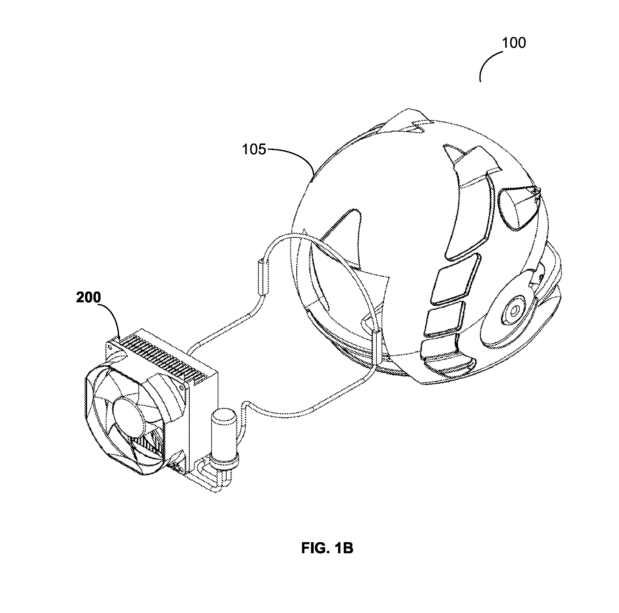
[0010] FIG. 1B is a schematic diagram shows the liquid temperature monitoring assembly outside the helmet in an isometric view.
[0011] FIG. 2A is a schematic diagram of a liquid temperature monitoring assembly according to an embodiment.
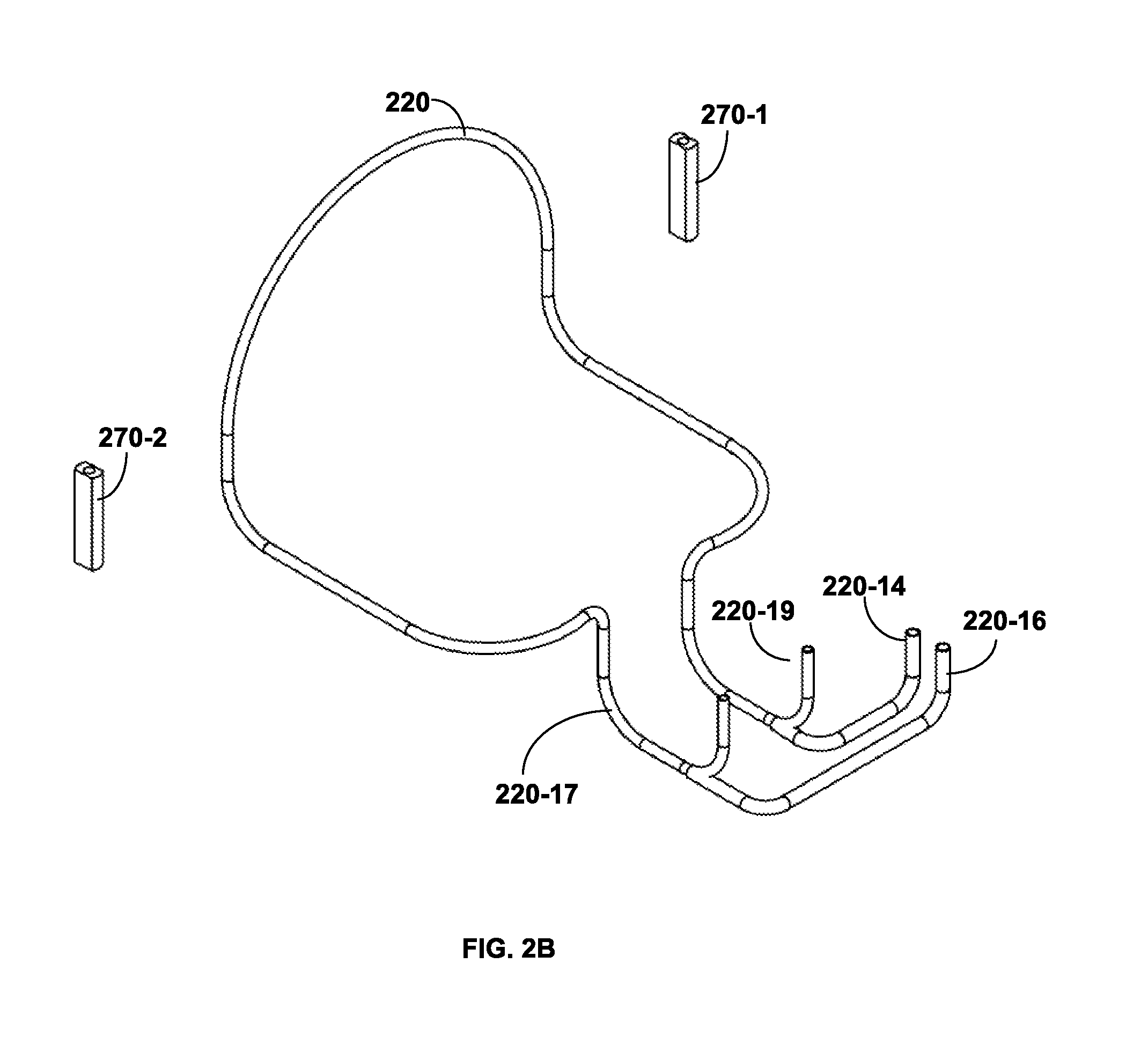
[0012] FIG. 2B is a schematic diagram of a pipe and a plurality of metallic components that are part of the liquid temperature monitoring assembly according to an embodiment.
[0013] FIG. 2C is a schematic diagram of the liquid temperature monitoring assembly according to an embodiment.
[0014] FIG. 3 is a schematic diagram from a bottom isometric view of the helmet including therein the liquid temperature monitoring assembly according to an embodiment.
[0015] FIG. 4A is a schematic diagram from a bottom view of the helmet including therein the liquid temperature monitoring assembly according to an embodiment.
[0016] FIG. 4B is a cutaway diagram from a side view of the helmet including therein the liquid temperature monitoring assembly according to an embodiment.
[0017] FIG. 4C is a schematic diagram from a front view of the helmet including therein the liquid temperature monitoring assembly according to an embodiment.
[0018] FIG. 5A is a schematic diagram from a bottom view of a detachable comfort padding for use with a helmet for controlling a temperature within the helmet according to an embodiment.
[0019] FIG. 5B is a schematic diagram from a top view of a detachable comfort padding for use with a helmet for controlling a temperature within the helmet according to an embodiment.
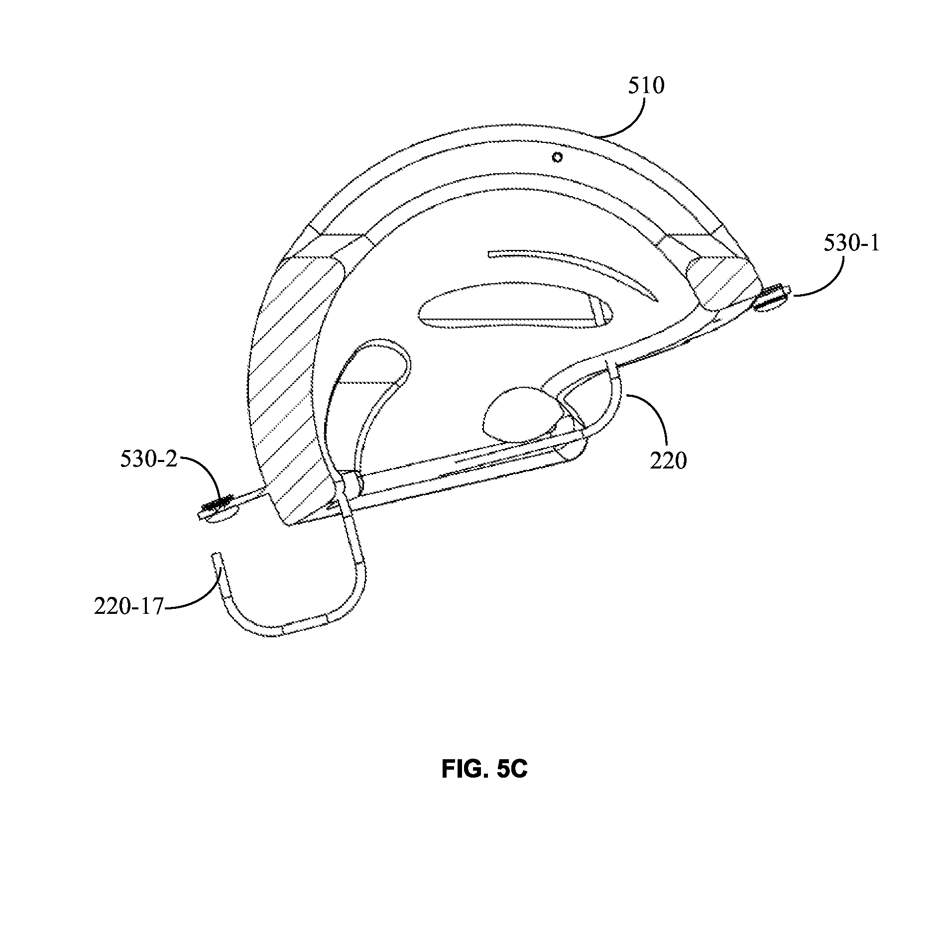
[0020] FIG. 5C is a schematic diagram from a side view of a detachable comfort padding for use with a helmet for controlling a temperature within the helmet according to an embodiment.
DETAILED DESCRIPTION
[0021] The embodiments disclosed by the disclosure are only examples of the many possible advantageous uses and implementations of the innovative teachings presented herein. In general, statements made in the specification of the present application do not necessarily limit any of the various claimed disclosures. Moreover, some statements may apply to some inventive features but not to others. In general, unless otherwise indicated, singular elements may be in plural and vice versa with no loss of generality. In the drawings, like numerals refer to like parts through several views.
[0022] A helmet configured to control the temperature within the helmet is disclosed. The helmet contains therein a pipe designed to drive through the pipe a cooled or heated liquid. The pipe is positioned with the helmet such that the pipe is in partial contact with the user's head body part when wearing the helmet.
[0023] FIG. 1A shows an example schematic diagram of a helmet 100 having a temperature control mechanism for controlling the temperature within the helmet 100 according to an embodiment. The helmet 100 includes a helmet shell 105 having an inner shape to generally conform to a person's head body part, and a liquid temperature monitoring assembly 200 that is further discussed herein below. The liquid temperature monitoring assembly may be connected to the helmet 100 or embedded within the helmet 100 as further described herein below. The liquid temperature monitoring assembly 200 facilitates the control of the temperature within the helmet.
[0024] FIG. 1B shows an example schematic diagram of the liquid temperature monitoring assembly in an isometric view. The liquid temperature monitoring assembly 200, as shown in FIG. 1B, is positioned outside the helmet 100, such that, several components that are usually located within the helmet 100, e.g. a pipe that is further described herein below, may be shown. It should be noted that the pipe and other components of the liquid temperature monitoring assembly 200 are utilized to increase and reduce the temperature within the helmet 100.
[0025] FIG. 2A shows an example schematic diagram of a liquid temperature monitoring assembly 200 adapted to control a temperature within the helmet 100 according to an embodiment. The liquid temperature monitoring assembly 200 includes a liquid container 210 containing therein a liquid. The liquid may be, for example, water, antifreeze, glycol-water mixture, and so on. The liquid container is further described herein below with respect of FIG. 3.
[0026] The helmet 100 further includes a pipe 220 positioned within the inner shape of the helmet shell 105 and transporting therein the liquid, such that the pipe is to be in partial contact with the person's head body part when wearing the helmet. The pipe 220 is further discussed with respect of FIG. 2B.
[0027] The liquid temperature monitoring assembly 200 further includes a thermoelectric module 230 configured to increase and reduce the temperature of at least one surface (not shown) connected to the module 230. The surface may be made of a conductive material such as a metal. The surface may be attached to the liquid container 210 such that the temperature of the liquid within the liquid container 210 is affected by the temperature of the surface. The thermoelectric module 230 may further include a fan 250 and a heatsink 260 designed to exchange the heat generated by the surface.
[0028] The helmet 100 further includes a pump 240. According to an embodiment, when the pump 140 is powered, the drive is structured to drive the liquid through the pipe 120 and the thermoelectric module 230, such that the temperature of the liquid in the pipe 120 is affected by the temperature within the liquid container 110. According to one embodiment, a power source is configured to activate the pump 140 and the thermoelectric module 130. The power source may be, for example, a battery, a rechargeable battery, a plurality of batteries, the motorcycle battery, and the like. The components of the pump 140 are further described with respect of FIG. 3.
[0029] The liquid temperature monitoring assembly 200 further includes a plurality of hollow metallic components 270-1 through 270-N (N is an integer number greater than 1). The hollow metallic components 270 may be embedded within a plurality of sections of the pipe 220 such that the hollow metallic components 270 are to be in at least partial contact with the person's head body part when wearing the helmet, allowing the liquid to flow throughout the pipe 220.
[0030] The hollow metallic components 270 enhance the cooling and heating capabilities of the pipe 220 such that when the head body part of the person touches the hollow metallic components 270, the effect of the liquid temperature monitoring assembly 200 is enhanced, as opposed to using only the pipe 220 for controlling the helmet 100 temperature. It should be noted that multiple hollow metallic components 270 may be integrated within the pipe 220. It should further be noted that the temperature in a section where a metallic component is positioned can be colder, when cold is desirable, and warmer, when heat is desirable, in comparison to the sections in which only the pipe 220 is positioned.
[0031] FIG. 2B shows an example exploded schematic diagram of the pipe 220 according to an embodiment. The pipe 220 may include a first pipe entry point 220-14 for the liquid to enter therein and a first pipe exit point 220-16 for the liquid to exit therefrom. In an embodiment, the pipe 220 may include a second pipe entry point 220-17 and a second pipe exit point 220-19 as further described herein below. FIG. 2B also shows an exploded view that presents two example hollow metallic components 270-1 and 270-2 that may be attached to an external side of the pipe 220. In an embodiment, the metallic components may be embedded within the pipe 220.
[0032] FIG. 2C shows an example schematic diagram of the liquid temperature monitoring assembly 200 according to an embodiment. Several components such as the fan 250, the heatsink 260, the pipe 220 and the hollow metallic component 270, are shown.
[0033] FIG. 3 shows an example bottom isometric schematic diagram of the helmet 100 according to an embodiment. The liquid container 210 includes an entry point 210-11 for the liquid and an exit point 210-13 for the liquid. In an embodiment, the first pipe entry point 220-17 is connected to the entry point 210-11 and the first pipe exit point 220-19 is connected to the exit point 210-13. The pump 240 includes an inlet flange 240-17 and an outlet flange 240-19. In an embodiment, the second pipe entry point 220-17 is connected to the inlet flange 240-17 and the second pipe exit point 220-19 is connected to the outlet flange 240-19. Thus, when the pump 240 is powered, the pump 240 drives the liquid through the pipe 220 and the thermoelectric module 230, such that the temperature of the liquid in the pipe 220 is affected by the temperature within the liquid container 210.
[0034] According to one embodiment, the pipe 220 is connected to the pump 240 and further connected to a liquid container 210 as further described herein above. The liquid container 210 is connected to the thermoelectric module (shown in FIG. 2A). The thermoelectric module (shown in FIG. 2A) is configured to affect the temperature of the liquid, when the liquid is within the liquid container 210. That is to say, when the thermoelectric module 230 generates cold, the surface attached thereto is affected and therefore the liquid container 210 affixed to the surface is affected too. Thus, the liquid within the liquid container 210 cools.
[0035] According to yet further embodiment, the cooled or heated liquid, generated by the thermoelectric module 230, is driven using the pump 240 from the liquid container 210 throughout the pipe 220 and goes back into the liquid container 210 for continuing the process.
[0036] FIGS. 4A, 4B and 4C show a schematic diagram of the inner shape of the helmet 100 having a pipe 220 therein according to an embodiment. The helmet shell 105 is the external side of the helmet 100 designed to protect the user from being injured. The pipe 220 is positioned within the inner shape of the helmet 100 such that the pipe 220 is to be in partial contact with the user's head body part when wearing the helmet 100. According to an embodiment, the pipe 220 may be connected to and/or embedded within a comfort padding (not shown) of the helmet 100 or other interior components of the helmet 100. Also described in FIG. 4 are the pump 240, the inlet flange 240-17 and the outlet flange 240-19.
[0037] According to one embodiment, at least a portion of the pipe 220 may be positioned within the helmet 100, however the liquid temperature monitoring assembly 200 designed to heat and cool the liquid with the pipe 220, may be in a carrier such as a designated backpack.
[0038] FIG. 5A shows an example diagram of a detachable comfort padding for use with a helmet for controlling a temperature within the helmet according to an embodiment. A pipe 220 is mounted within a detachable comfort padding 510 such that the pipe 220 is to be in partial contact with a head body part of a person wearing the helmet. The pipe 220 may include a plurality of entry points and a pipe exit points adapted to accept a liquid flowing therein. In an embodiment, the pipe 220 is embedded within a designated slit of the detachable comfort padding.
[0039] The detachable comfort padding 510 may be attached to an inner side of different helmets using a plurality of connecting elements 530, such as the connecting elements 530-1 through 530-3. The connecting elements 530 may be for example, buttons, straps, etc. Thus, the detachable comfort padding 510 having therein the pipe 220 may be installed in various existing types of helmets. Examples for such elements include, Shoei.RTM. helmets, LS2.RTM. helmets, AGV.RTM. helmets, and so on. According to an embodiment, the pipe 220 is embedded within a designated slit of the detachable comfort padding 410.
[0040] FIG. 5B shows an example schematic diagram from a top view of a detachable comfort padding 510 for use with a helmet for controlling a temperature within the helmet according to an embodiment. The detachable comfort padding 510 includes a plurality of entry points and a pipe exit points adapted to accept a liquid flowing through the pipe 220, such as the pipe entry point 220-17 and the pipe exit point 220-19.
[0041] FIG. 5C shows an example schematic diagram from a side view of a detachable comfort 510 padding for use with a helmet for controlling a temperature within the helmet according to an embodiment.
[0042] As used herein, the phrase "at least one of" followed by a listing of items means that any of the listed items can be utilized individually, or any combination of two or more of the listed items can be utilized. For example, if a system is described as including "at least one of A, B, and C," the system can include A alone; B alone; C alone; 2A; 2B; 2C; 3A; A and B in combination; B and C in combination; A and C in combination; A, B, and C in combination; 2A and C in combination; A, 3B, and 2C in combination; and the like.
[0043] It should be understood that any reference to an element herein using a designation such as "first," "second," and so forth does not generally limit the quantity or order of those elements. Rather, these designations are generally used herein as a convenient method of distinguishing between two or more elements or instances of an element. Thus, a reference to first and second elements does not mean that only two elements may be employed there or that the first element must precede the second element in some manner. Also, unless stated otherwise, a set of elements comprises one or more elements.
[0044] All examples and conditional language recited herein are intended for pedagogical purposes to aid the reader in understanding the principles and the concepts contributed by the inventor to furthering the art, and are to be construed as being without limitation to such specifically recited examples and conditions. Moreover, all statements herein reciting principles, aspects, and embodiments, as well as specific examples thereof, are intended to encompass both structural and functional equivalents thereof. Additionally, it is intended that such equivalents include both currently known equivalents as well as equivalents developed in the future, i.e., any elements developed that perform the same function, regardless of structure.
* * * * *
D00000
D00001
D00002
D00003
D00004
D00005
D00006
D00007
D00008
D00009
D00010
D00011
D00012
XML
uspto.report is an independent third-party trademark research tool that is not affiliated, endorsed, or sponsored by the United States Patent and Trademark Office (USPTO) or any other governmental organization. The information provided by uspto.report is based on publicly available data at the time of writing and is intended for informational purposes only.
While we strive to provide accurate and up-to-date information, we do not guarantee the accuracy, completeness, reliability, or suitability of the information displayed on this site. The use of this site is at your own risk. Any reliance you place on such information is therefore strictly at your own risk.
All official trademark data, including owner information, should be verified by visiting the official USPTO website at www.uspto.gov. This site is not intended to replace professional legal advice and should not be used as a substitute for consulting with a legal professional who is knowledgeable about trademark law.