Hysterectomy Model
Black; Katie ; et al.
U.S. patent application number 16/249276 was filed with the patent office on 2019-05-16 for hysterectomy model. The applicant listed for this patent is Applied Medical Resources Corporation. Invention is credited to Katie Black, Natasha Felsinger, Gregory Hofstetter.
| Application Number | 20190147766 16/249276 |
| Document ID | / |
| Family ID | 56194598 |
| Filed Date | 2019-05-16 |


View All Diagrams
| United States Patent Application | 20190147766 |
| Kind Code | A1 |
| Black; Katie ; et al. | May 16, 2019 |
HYSTERECTOMY MODEL
Abstract
A surgical simulator for surgical training is provided. The simulator includes a frame defining an enclosure and a simulated tissue model located inside an enclosure. The simulated tissue model is adapted for practicing hysterectomies and includes at least a simulated uterus and a simulated vagina. The simulated tissue model is suspending inside the enclosure with two planar sheets of silicone such that the tissue model is located between the two sheets each of which form a fold and are in turn connected to the frame. The frame may be shaped like a cylinder and located inside a cavity of a larger laparoscopic trainer having a penetrable simulated abdominal wall. The tissue model is interchangeable and accessible laterally through an aperture provided in a support leg of the trainer.
| Inventors: | Black; Katie; (Rancho Santa Margarita, CA) ; Hofstetter; Gregory; (Rancho Santa Margarita, CA) ; Felsinger; Natasha; (Rancho Santa Margarita, CA) | ||||||||||
| Applicant: |
|
||||||||||
|---|---|---|---|---|---|---|---|---|---|---|---|
| Family ID: | 56194598 | ||||||||||
| Appl. No.: | 16/249276 | ||||||||||
| Filed: | January 16, 2019 |
Related U.S. Patent Documents
| Application Number | Filing Date | Patent Number | ||
|---|---|---|---|---|
| 15202327 | Jul 5, 2016 | 10223936 | ||
| 16249276 | ||||
| PCT/US2016/036664 | Jun 9, 2016 | |||
| 15202327 | ||||
| 62173180 | Jun 9, 2015 | |||
| Current U.S. Class: | 434/273 |
| Current CPC Class: | G09B 23/285 20130101; G09B 23/281 20130101 |
| International Class: | G09B 23/28 20060101 G09B023/28 |
Claims
1. A surgical simulator for surgical training comprising: a simulated pelvis defining an enclosure having and inner surface, an outer surface and at least one opening; a simulated tissue model including a simulated uterus; a first sheet of silicone; and a second sheet of silicone, the simulated tissue model being suspended by at least one of the first sheet and the second sheet within the enclosure of the simulated pelvis.
2. The surgical simulator of claim 1 wherein the simulated tissue model is connected to and located between the first and second sheets of silicone.
3. The surgical simulator of claim 1 wherein the first sheet and the second sheet are connected to the simulated pelvis.
4. The surgical simulator of claim 1 wherein the simulated uterus further comprises a simulated cervix located inside the simulated uterus.
5. The surgical simulator of claim 4 wherein the simulated cervix is made of a solid high durometer silicone and includes a slit.
6. The surgical simulator of claim 5 wherein the simulated uterus further comprises simulated fallopian tubes connected to simulated ovaries.
7. The surgical simulator of claim 6 wherein the simulated uterus is made of a foam material combined with silicone.
8. The surgical simulator of claim 4 wherein the simulated uterus weighs 300 to 500 grams.
9. The surgical simulator of claim 1 wherein the simulated uterus has a bulbous portion at a distal end connected to a simulated vagina having a tubular portion at a proximal end, the tubular potion having a lumen accessible through the at least one opening of the simulated pelvis.
10. A surgical simulator for surgical training comprising: a simulated pelvic frame defining a lumen therethrough; and a simulated tissue model comprising a simulated colon located within the lumen of the simulated pelvic frame.
11. The surgical simulator of claim 10 wherein the simulated pelvic frame being cylindrical and comprises a first surface interconnected to a second surface.
12. The surgical simulator of claim 11 wherein the first surface defines an inner surface of the simulated pelvic frame, the simulated colon being laid on the first surface along a vertical axis.
13. The surgical simulator of claim 12 wherein the simulated tissue model further comprises a simulated bladder located within the lumen of the simulated pelvic frame.
14. The surgical simulator of claim 13 further comprising a silicone sheet connected to the simulated bladder and the simulated pelvic frame, the simulated bladder being disposed between the silicone sheet and the simulated pelvic frame.
15. The surgical simulator of claim 13 wherein the simulated bladder is connected to the first surface along the vertical axis.
16. The surgical simulator of claim 12 wherein the second surface defines an outer surface of the simulated pelvic frame.
17. The surgical simulator of claim 16 wherein the simulated pelvic frame is compressible.
18. The surgical simulator of claim 17 wherein the simulated pelvic frame is made of a flexible foam material.
19. The surgical simulator of claim 16 wherein the simulated pelvic frame includes one or more cutouts extending between the first surface and the second surface.
20. The surgical simulator of claim 10 further comprising a webbing connected to the simulated pelvis frame and the simulated tissue model, the webbing suspending the simulated tissue model within the simulated pelvis frame.
Description
CROSS-REFERENCE TO RELATED APPLICATIONS
[0001] This patent application is a continuation of U.S. patent application Ser. No. 15/202,327 entitled "Hysterectomy model" filed on Jul. 5, 2016 which is a continuation of International Patent Application PCT/US2016/036664 entitled "Hysterectomy model" filed on Jun. 9, 2016 which claims priority to and benefit of U.S. Provisional Patent Application Ser. No. 62/173,180 entitled "Hysterectomy model" filed on Jun. 9, 2015, the entire disclosures of all these applications are hereby incorporated by reference as if set forth in full herein.
FIELD OF THE INVENTION
[0002] This application is generally related to surgical training tools, and in particular, to simulated tissue structures and models for teaching and practicing various surgical techniques and procedures related but not limited to laparoscopic, endoscopic and minimally invasive surgery.
BACKGROUND OF THE INVENTION
[0003] Medical students as well as experienced doctors learning new surgical techniques must undergo extensive training before they are qualified to perform surgery on human patients. The training must teach proper techniques employing various medical devices for cutting, penetrating, clamping, grasping, stapling, cauterizing and suturing a variety of tissue types. The range of possibilities that a trainee may encounter is great. For example, different organs and patient anatomies and diseases are presented. The thickness and consistency of the various tissue layers will also vary from one part of the body to the next and from one patient to another. Different procedures demand different skills. Furthermore, the trainee must practice techniques in various anatomical environs that are influenced by factors such as the size and condition of the patient, the adjacent anatomical landscape and the types of targeted tissues and whether they are readily accessible or relatively inaccessible.
[0004] Numerous teaching aids, trainers, simulators and model organs are available for one or more aspects of surgical training. However, there is a need for models or simulated tissue elements that are likely to be encountered in and that can be used for practicing endoscopic and laparoscopic, minimally invasive, transluminal surgical procedures. In laparoscopic surgery, a trocar or cannula is inserted to access a body cavity and to create a channel for the insertion of a camera such as a laparoscope. The camera provides a live video feed capturing images that are then displayed to the surgeon on one or more monitors. At least one additional small incision is made through which another trocar/cannula is inserted to create a pathway through which surgical instruments can be passed for performing procedures observed on the monitor. The targeted tissue location such as the abdomen is typically enlarged by delivering carbon dioxide gas to insufflate the body cavity and create a working space large enough to accommodate the scope and instruments used by the surgeon. The insufflation pressure in the tissue cavity is maintained by using specialized trocars. Laparoscopic surgery offers a number of advantages when compared with an open procedure. These advantages include reduced pain, reduced blood and shorter recovery times due to smaller incisions.
[0005] Laparoscopic or endoscopic minimally invasive surgery requires an increased level of skill compared to open surgery because the target tissue is not directly observed by the clinician. The target tissue is observed on monitors displaying a portion of the surgical site that is accessed through a small opening. Therefore, clinicians need to practice visually determining tissue planes, three-dimensional depth perception on a two-dimensional viewing screen, hand-to-hand transfer of instruments, suturing, precision cutting and tissue and instrument manipulation. Typically, models simulating a particular anatomy or procedure are placed in a simulated pelvic trainer where the anatomical model is obscured from direct visualization by the practitioner. Ports in the trainer are employed for passing instruments to practice techniques on the anatomical model hidden from direct visualization. Simulated pelvic trainers provide a functional, inexpensive and practical means to train surgeons and residents the basic skills and typical techniques used in laparoscopic surgery such as grasping, manipulating, cutting, tying knots, suturing, stapling, cauterizing as well as how to perform specific surgical procedures that utilized these basic skills. Simulated pelvic trainers are also effective sales tools for demonstrating medical devices required to perform these laparoscopic procedures.
[0006] One procedure is a hysterectomy in which the uterus is removed. The hysterectomy may be performed vaginally extracting the uterus through the vaginal canal or abdominally through a small incision in the abdomen. The vaginal hysterectomy is historically hard to train on as the field of view is limited. Unlike laparoscopic procedures, there is no camera that is projecting the surgery onto a screen and unlike open procedures there is not a wide incision that can be viewed by multiple people. As such, the best way to teach a vaginal hysterectomy is through a simulated model. Therefore, there is a need for a model for training hysterectomy procedures.
SUMMARY OF THE INVENTION
[0007] According to one aspect of the invention, a surgical simulator for surgical training is provided. The surgical simulator includes a simulated pelvic frame having a proximal end and a distal end. The simulated pelvis defines an enclosure having and inner surface, an outer surface and at least one opening at the proximal end. The surgical simulator includes a simulated tissue model including a simulated uterus having a bulbous portion at a distal end connected to a simulated vagina having a tubular portion at a proximal end. The simulated tissue model is connected to the simulated pelvis such that the simulated tissue model is suspended within the enclosure of the simulated pelvis with the bulbous portion of the simulated uterus located near the distal end and the tubular portion of the simulated vagina located near the proximal end of the simulated pelvis. The tubular portion has a lumen accessible through the at least one opening in the simulated pelvis.
[0008] According to another aspect of the invention, a surgical simulator for surgical training is provided. The simulator includes a simulated pelvic frame having an inner surface and an outer surface defining a substantially uniform thickness therebetween. The simulated pelvic frame has a substantially cylindrical shape. The cylindrical shape includes an open proximal end and an open distal end defining a lumen therebetween. The simulated pelvic frame has a longitudinal axis and a top end and a bottom end. The simulated tissue model includes one or more of a simulated uterus, vagina, cervix, fallopian tube, ovary, ligament, vasculature, bladder, and colon. The simulated tissue model is removably connected to the simulated pelvic frame such that the simulated tissue model is suspended within the lumen and allowed to pendulate in response to manipulation by a user.
[0009] According to another aspect of the invention, a surgical simulator for surgical training is provided. The simulator includes a base, a top cover connected to and spaced apart from the base to define an internal cavity between the top cover and the base. The simulator includes at least two legs spaced apart from each other and interconnecting and spacing apart the top cover and base. One leg of the at least two legs has an aperture facing the internal cavity. The simulator further includes a simulated uterus at a distal end connected to a simulated vagina at a proximal end. The simulated vagina defines a lumen having a proximal opening. The proximal opening is interconnected with the aperture such that the aperture provides an access port to the lumen of the simulated vagina. The simulated vagina and simulated uterus extending into the internal cavity. The one or more of the simulated uterus and simulated vagina is suspended inside the internal cavity.
BRIEF DESCRIPTION OF THE DRAWINGS
[0010] FIG. 1 is a top perspective view of a surgical training device according to the present invention.
[0011] FIG. 2 is an antero-cephalad, top perspective view of a model according to the present invention.
[0012] FIG. 3A is a top perspective view of a pelvic frame according to the present invention.
[0013] FIG. 3B is a top perspective view of a pelvic frame according to the present invention
[0014] FIG. 3C is a top perspective view of a pelvic frame according to the present invention.
[0015] FIG. 3D is a top view of a pelvic frame in a flat orientation according to the present invention.
[0016] FIG. 4A is a caudal end view of a model inside a surgical training device according to the present invention.
[0017] FIG. 4B is a lateral side view of a model inside a surgical training device according to the present invention.
[0018] FIG. 4C is a lateral side view of a model inside a surgical training device according to the present invention.
[0019] FIG. 4D is an antero-caudal, top perspective view of a model inside a surgical training device according to the present invention.
[0020] FIG. 4E is a cephalad end view of a model inside a surgical training device according to the present invention.
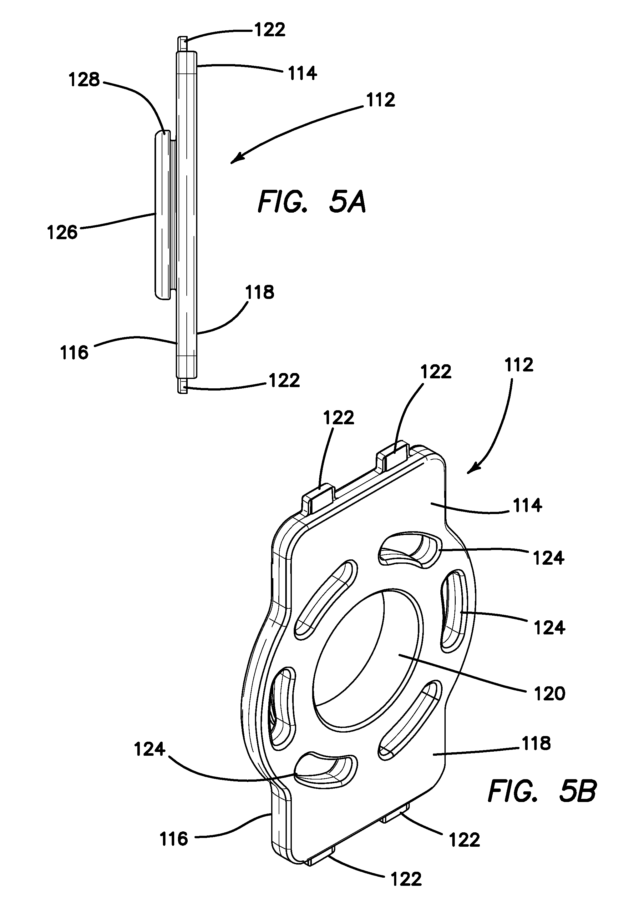
[0021] FIG. 5A is a side view of a transvaginal adapter according to the present invention.
[0022] FIG. 5B is a top perspective view of a transvaginal adapter according to the present invention.
[0023] FIG. 6A is a side view of a transvaginal adapter according to the present invention.
[0024] FIG. 6B is a top perspective view of a transvaginal adapter according to the present invention.
DETAILED DESCRIPTION OF THE INVENTION
[0025] A surgical training device 10 that is configured to mimic the torso of a patient such as the abdominal region is shown in FIG. 1. The surgical training device 10 provides a body cavity 12 substantially obscured from the user for receiving simulated or live tissue or model organs or training models of the like described in this invention. The body cavity 12 is accessed via a tissue simulation region 14 that is penetrated by the user employing devices to practice surgical techniques on the tissue or practice model found located in the body cavity 12. Although the body cavity 12 is shown to be accessible through a tissue simulation region, a hand-assisted access device or single-site port device may be alternatively employed to access the body cavity 12. An exemplary surgical training device is described in U.S. Patent Application Ser. No. 13/248,449 entitled "Portable Laparoscopic Trainer" filed on Sep. 29, 2011 and incorporated herein by reference in its entirety. The surgical training device 10 is particularly well suited for practicing laparoscopic or other minimally invasive surgical procedures.
[0026] Still referencing FIG. 1, the surgical training device 10 includes a top cover 16 connected to and spaced apart from a base 18 by at least one leg 20. FIG. 1 shows a plurality of legs 20. The surgical training device 10 is configured to mimic the torso of a patient such as the abdominal region. The top cover 16 is representative of the anterior surface of the patient and the space 12 between the top cover 16 and the base 18 is representative of an interior of the patient or body cavity where organs reside. The surgical trainer 10 is a useful tool for teaching, practicing and demonstrating various surgical procedures and their related instruments in simulation of a patient undergoing a surgical procedure. Surgical instruments are inserted into the cavity 12 through the tissue simulation region 14 as well as through pre-established apertures 22 in the top cover 16. Various tools and techniques may be used to penetrate the top cover 16 to perform mock procedures on simulated organs or practice models placed between the top cover 16 and the base 18. The base 18 includes a model-receiving area 24 or tray for staging or holding a simulated tissue model or live tissue. The model-receiving area 24 of the base 18 includes frame-like elements for holding the model (not shown) in place. To help retain a simulated tissue model or live organs on the base 18, a clip attached to a retractable wire is provided at locations 26. The retractable wire is extended and then clipped to hold the tissue model in position substantially beneath the tissue simulation region 14. Other means for retaining the tissue model include a patch of hook-and-loop type fastening material (VELCRO.RTM.) affixed to the base 18 in the model receiving area 24 such that it is removably connectable to a complementary piece of hook-and-loop type fastening material (VELCRO.RTM.) affixed to the model.
[0027] A video display monitor 28 that is hinged to the top cover 16 is shown in a closed orientation in FIG. 1. The video monitor 28 is connectable to a variety of visual systems for delivering an image to the monitor. For example, a laparoscope inserted through one of the pre-established apertures 22 or a webcam located in the cavity and used to observe the simulated procedure can be connected to the video monitor 28 and/or a mobile computing device to provide an image to the user. Also, audio recording or delivery means may also be provided and integrated with the trainer 10 to provide audio and visual capabilities. Means for connecting a portable memory storage device such as a flash drive, smart phone, digital audio or video player, or other digital mobile device is also provided, to record training procedures and/or play back pre-recorded videos on the monitor for demonstration purposes. Of course, connection means for providing an audio visual output to a screen larger than the monitor is provided. In another variation, the top cover 10 does not include a video display but includes means for connecting with a laptop computer, a mobile digital device or tablet and connecting it by wire or wirelessly to the trainer.
[0028] When assembled, the top cover 16 is positioned directly above the base 18 with the legs 20 located substantially around the periphery and interconnected between the top cover 16 and base 18. The top cover 16 and base 18 are substantially the same shape and size and have substantially the same peripheral outline. The internal cavity is partially or entirely obscured from view. In the variation shown in FIG. 1, the legs include openings to allow ambient light to illuminate the internal cavity as much as possible and also to advantageously provide as much weight reduction as possible for convenient portability. The top cover 16 is removable from the legs 20 which in turn are removable or collapsible via hinges or the like with respect to the base 18. Therefore, the unassembled trainer 10 has a reduced height that makes for easier portability. In essence, the surgical trainer 10 provides a simulated body cavity 12 that is obscured from the user. The body cavity 12 is configured to receive at least one surgical model accessible via at least one tissue simulation region 14 and/or apertures 22 in the top cover 16 through which the user may access the models to practice laparoscopic or endoscopic minimally invasive surgical techniques.
[0029] A model 30 for practicing hysterectomies and, in particular, for practicing vaginal hysterectomies according to the present invention is shown in FIG. 2. The model 30 is configured to be placed inside the surgical training device 10 described above or other similar surgical trainer. The model 30 includes a simulated uterus 32 connected to a frame 34 with a first sheet 36 and a second sheet 38. The simulated uterus 32 includes a bulbous portion 40 defining a hollow simulated uterine cavity 42. The bulbous portion 40 is connected to a tubular portion 44 defining a vaginal canal 46 having an opening 48. The simulated uterus 32 further includes a simulated cervix 50 (shown in FIG. 4A) located inside the simulated uterus 32 in a location substantially between the uterine cavity 42 and the vaginal canal 46. The simulated cervix 50 includes a slit 52. The simulated cervix 50 is made of a solid, high durometer silicone.
[0030] The simulated uterus 32 further includes simulated fallopian tubes 54 connected to ovaries 56. The simulated uterus 32, fallopian tubes 54 and ovaries 56 are made of silicone or other elastomeric material and may include other material such as foam material combined with the silicone. The simulated uterus 32 is made of silicone or lighter foam such as urethane or silicone foam or a combination of the two. The silicone construction imparts the simulated uterus 32 with a more realistic weight when the attached simulated cervix 50 is being pulled and manipulated. The simulated uterus 32 made of foam makes the simulated uterus 32 easier to suspend inside the simulated pelvic cavity. Also, when removing the simulated uterus 32 the lightweight foam flexes more easily than a simulated uterus 32 made of higher durometer silicone allowing a larger simulated uterus 32 to be placed into the model 30 and still be removed. The foam uterus 32 would compress and flex as it is being removed through the vaginal opening 48 similar to an actual surgery. The simulated uterus 32 is approximately 300-500 grams and the simulated uterus 32 is composed of a selected durometer foam to accurately represent the size and weight of a real uterus that could normally be removed vaginally without significant morcellation. In another variation, the simulated uterus 32 is a combination of silicone and foam to give a more realistic look to the simulated uterus 32 while still having the flexibility of the foam. The foam can be cast and then the silicone can be applied over the foam such as, for example, on a rotational mold. The simulated uterus 32 is generally pink in color and the fallopian tubes 54 and ovaries are clear or white in color. Furthermore, the simulated uterus 32 may include embedded tumors, cysts and/or ectopic pregnancies in the fallopian tubes 54. The model 30 may further include simulated vasculature 58 such as blood vessels. The simulated vasculature 58 is made of solid or hollow tubular silicone or other suitable elastomer. Liquid may be included inside the hollow tubing of the simulated vasculature 58. The simulated vasculature 58 that simulates blood vessels may be red in color. The model 30 may also include simulated ligaments 59 such as the uteralsacral ligament 59 and made of silicone material as seen in FIGS. 2 and 4E. The model 30 may further include the round and tubo ovarian ligaments 61 attached to the frame 34 shown in FIG. 2.
[0031] With additional reference to FIGS. 3A-3D, the frame 34 comprises a cylindrical-like shape defining an interior/lumen 60. The frame 34 includes a first surface 62 interconnected to a second surface 64 defining a thickness therebetween. The first surface 62 defines the inner surface of the cylindrical-like shape of the frame 34 and the second surface 64 defines an outer surface of the cylindrical-like shape of the frame 34. The frame 34 is made of flexible foam material that is also slightly compressible. The frame 34 includes one or more cutouts 66 extending between the first surface 62 and the second surface 64 to define an outer perimeter and apertures. In one variation, the frame 34 is made of a sheet of foam material that is cut according to a pattern shown in FIG. 3D. FIG. 3D illustrates the outer perimeter having a top 68 and a bottom 70 interconnected by a first side and a second side 72, 74. The top 68 includes two curved portions 76a, 76b interconnected at a first protrusion 78 along a vertical axis. The two curved portions 76a, 76b represent the left and right illium/iliac crest. The bottom 70 includes a second protrusion 80 along the vertical axis. The first protrusion 78 represents the sacrum of a human pelvis and the second protrusion 80 represents the coccyx. The first side 72 includes a first lower lobe 82 having a first aperture 86 and the second side 74 includes a second lower lobe 84 having a second aperture 88. The first and second lower lobes 82, 84 represent the left and right ischium and the first aperture 86 and the second aperture 88 represent the obturator foramen of the human pelvis. A piece of foam having a thickness is cut to have the flat pattern shape shown in FIG. 3D. Then the piece of foam is curved such that the first lower lobe 82 and second lower lobe 84 join together in a cylinder-like configuration. Where the two lobes 82, 84 are joined, represent the pubic bone/pubis/pubis symphysis. The two lobes 82, 84 can be joined by adhesive or connected in another suitable manner. In another variation, the two lobes 82, 84 are not joined together but remain spaced apart in a semi-cylindrical-like or split cylinder configuration. The frame 34 is bendable and may be made of a material that retains its shape after bending such as aluminum. Also, the clips 26 and wire that are connected to the trainer 10 may be used to hold the two lobes 82, 84 in an upward orientation and in a cylindrical-like configuration while inside the trainer 10. The anatomy of the pelvis is shown in FIG. 7.
[0032] The frame 34 is made of soft, compressible, semi-rigid foam that can be die cut and then formed into the correct shape with adhesive. If the frame 34 is made of harder plastic, it could be a thin thermoform that is initially formed into the correct shape or a thicker plastic that is cut into the pelvis shape and then formed into a cylindrical shape with heat. The frame 34 may also be made of deformable metal that holds its shape. The frame 34 is not a perfect replica of the anatomy and need only include certain features selected to practice certain procedures that require those specific features as anatomical reference points or visual landmarks for the practitioner. For example, for practicing a vaginal hysterectomy, the important features of the pelvis are the restriction of the pelvic inlet and the attachments to the pelvic sidewall. For practicing a transanal total mesorectal excision (taTME), the L-shape of the sacrum is an important landmark. For hernia procedures, the pubic tubercle is an important landmark. The frame 34 can be made to have all anatomically correct features or only the ones needed for the specific procedure. As such, the frame 34 and model 30 can be used for the simulation of a vaginal hysterectomy, abdominal hysterectomy, colectomy, hernia, taTME, and other pelvic procedures. In another variation, the frame 34 forms a conical shape or frusto-conical shape having an open proximal and open distal ends.
[0033] With reference back to FIG. 2, the model 30 may further include a simulated bladder 90. The simulated bladder 90 is a hollow, air-filled component typically made of silicone or other elastomeric material. In another variation, the simulated bladder contains liquid. The simulated bladder 90 is connected to the frame 34 with adhesive or other means. It is connected to the first surface 62 or inner surface of the frame 34. The simulated bladder 90 is attached in alignment with the vertical axis in the location of where the two lobes 82, 84 are in juxtaposition in a location representative of the pubis. When connected the simulated bladder 90 extends into the lumen 60 of the frame 34. The simulated bladder 90 may further include a simulated ureter 94. In one variation, the simulated ureter 94 is connected to the simulated bladder 90. The simulated ureter is made of solid or hollow tubular silicone.
[0034] Still referencing FIG. 2, the model 30 may further include a simulated colon 92 or bowel portion. The simulated colon 92 is a tubular structure that includes a lumen. The simulated colon 92 is laid on the first surface 62 inside the interior 60 of the frame 34 and substantially along the vertical axis and against the second protrusion 80 of the frame 34. Adhesive may be used to attach the simulated colon 92 to the frame 34. The simulated colon 92 is made of silicone or other suitable elastomeric material and colored pink or other suitable color and may or may not include simulated tumors.
[0035] The first sheet 36 is a thin layer of clear silicone material having a top surface 96 and a bottom surface 98 and a first end 100 and a second end 102. The first sheet 36 is transparent and at least one of the top surface 96 and the bottom surface 98 is textured in one variation. The first sheet 36 is attached to the simulated uterus 32. In particular, the bottom surface 98 of the first sheet 36 near the first end 100 is attached along at least a portion of the length of simulated uterus 32 to one or more of the bulbous portion 40 and tubular portion 44 as shown in FIG. 2. The first sheet 36 is then folded back toward the top of the model 30 and toward the first end 100 of the first sheet 36 creating a fold near the tubular portion 44 of the simulated uterus 32. At least a portion of the first sheet 36 near the second end 102 of the first sheet 36 is attached to the frame 34 such that the bottom surface 98 of the first sheet 36 is adhered to the frame 34 in the general location of where the two lobes 82, 84 are in juxtaposition to create a cylinder-like configuration for the frame 34. The attachment of the first sheet 36 may also serve to hold the frame 34 in the cylindrical-like configuration. Adhesive is used to attach the bottom surface 98 of the first sheet 36 to the frame 34. The bottom surface 98 of the first sheet 36 is attached to the first surface 62 or inner surface of the frame 34 and then folded around a portion of the first side 72 and second side 74 of the frame 34. If a simulated bladder 90 is employed in the model 30, then the second end 102 of the first sheet 36 is also attached with adhesive to the outer surface of the simulated bladder 90 capturing the simulated bladder 90 between the frame 34 and the first sheet 36. A portion of the second end 102 of the first sheet 36 is folded around the edge of the frame 34 and attached to the second surface 64 of the frame 34 such that at least part of the second end 102 of the first sheet 36 is resident above the second or outer surface 64 of the frame 34 as visible in FIG. 4D. The first sheet 36 is sized and configured to suspend the simulated uterus 32 inside the interior 60 of the frame 34. Simulated vasculature 58 may be attached to the top surface 96 or bottom surface 98 of the first sheet 36. The configuration of the first sheet 36 forms a pocket-like structure wherein the top surface 96 of the first sheet 36 is folded and at least in part facing itself. The first sheet 36 creates a webbing of suspension that simulates the peritoneum layer.
[0036] The second sheet 38 is a thin layer of clear silicone material having a top surface 104 and a bottom surface 106 and a first end 108 and a second end 110. The second sheet 38 is transparent and at least one of the top surface 104 and the bottom surface 106 is textured in one variation. The second sheet 38 is attached to the simulated uterus 32. In particular, the bottom surface 106 of the second sheet 38 near the first end 108 is attached along at least a portion of the length of simulated uterus 32 to one or more of the bulbous portion 40 and tubular portion 44 on a side opposite from where the first sheet 36 is attached. The first sheet 36 is attached to the anterior side of the model 30 which is also the anterior side of the simulated uterus 32. The second sheet 38 is attached to the posterior side of the model 30 which is also the posterior side of the simulated uterus 32. After being attached to the posterior side of the simulated uterus 32, the second sheet 38 is then folded back toward the top of the model 30 and toward the first end 108 of the second sheet 38 creating a fold near the tubular portion 44 of the simulated uterus 32. At least a portion of the second sheet 38 near the second end 110 of the second sheet 38 is attached to the frame 34 such that the bottom surface 106 of the second sheet 38 is adhered to the frame 34 in the general location of the second protrusion 80. Adhesive is used to attach the bottom surface 106 of the second sheet 38 to the frame 34. The bottom surface 106 of the second sheet 38 is attached to the first surface 62 or inner surface of the frame 34 and may be folded around the edge of the frame 34 such that at least part of the second end 110 of the second sheet 38 is connected to second or outer surface 64 of the frame 34. If a simulated colon 92 is employed in the model 30, then the second end 110 of the second sheet 38 is also attached with adhesive to the outer surface of the simulated colon 92 or at least overlaying and not attached with adhesive such that at least a portion of the simulated colon 92 is captured or located between the frame 34 and the second sheet 38. The second sheet 38 is sized and configured to suspend the simulated uterus 32 inside the interior 60 of the frame 34 if the model 30 is turned over. Simulated vasculature 58 may be attached to the top surface 104 or bottom surface 106 of the second sheet 38. The configuration of the second sheet 38 forms a pocket-like structure wherein the top surface 104 of the second sheet 38 is folded and at least in part facing itself. The second sheet 38 creates a suspended webbing that simulates the peritoneum layer.
[0037] With reference now to FIGS. 4A-4E, the model 30 is shown placed inside a surgical training device 10 of the like described with respect to FIG. 1. The model 30 is shown inside the body cavity 12 and oriented such that the top 68 of the frame 34 is in the cephalad direction of the simulated training device 10 and the vaginal opening 48 of the simulated uterus 32 faces the caudal direction of the simulated training device 10. The model 30 can be connected to the surgical training device 10 with the clips 26 attached to the trainer 10. The retractable clips 26 can be pulled out and the clips 26 attached to any portion of the model 30 such as to the frame 34 of the model 30. Also, the second or outer surface 64 of the model 30 may include a hook-and-loop type fastener configured to attach to a complementary portion of hook-and-loop type fastener connected to the base 18 of the trainer 10. Together with one or more fasteners such as the clips 26 and/or hook-and-loop type fasteners, the model 30 is securely attached to the trainer 10 such that it can be manipulated in simulated surgery without dislodging the model 30 from the body cavity 12 of the trainer 10. The model 30 is further connected to the trainer 10 via a transvaginal adapter 112 that is sized and configured to connect between the top cover 16 and the base 18 as an additional leg 20 positioned at the caudal direction of the surgical training device 10.
[0038] Turning now to FIGS. 5A-5B and 6A-6B, there is shown a transvaginal adapter 112. With reference also back to FIG. 1, there is shown a top cover supported above the base by five legs 20. In one variation, a sixth leg 20 is provided as shown in FIGS. 4A-4D in the form of the transvaginal adapter 112. The trainer 10 may be assembled with an optional sixth support structure or leg which is configured for simulating transvaginal surgery including transvaginal hysterectomies.
[0039] The transvaginal adapter 112 includes a flat plate 114 having an inner surface 116 for facing toward the interior of the trainer and an outer surface 118 for facing outwardly towards the user. The plate 114 has a rectangular shape and includes an aperture 120 passing through the plate 108 from the inner surface 116 to the outer surface 118. In one variation, the aperture 120 is circular in shape. In another variation, the aperture 120 is elongate elliptical oval-like in shape and oriented vertically along the longitudinal axis of the adapter 112. In another variation, the aperture 120 is elongate elliptical oval-like in shape and oriented perpendicularly to the longitudinal axis of the adapter. As shown in FIGS. 5A-6B, the plate 114 also includes means such as tabs 122 or a U-shaped channel for inserting to connect the transvaginal adapter 112 to the top cover 16 and to the base 18 to help support and space apart the top cover 16. The transvaginal adapter 112 is located between the top cover 16 and the base 18 and provides a side access aperture 16 lateral to the trainer 10 or substantially perpendicular to the top cover 16 and the base 18. The plate 114 further includes a plurality of molding apertures 124 surrounding or encompassing the main aperture 120 configured for overmolding a soft simulated vaginal tissue interface made of silicone or the like. In another variation the interface is insertable into the aperture 120 of the transvaginal adapter 112. The tissue interface (not shown) includes an aperture that is substantially coaxial with the plate aperture 120. At the inner surface of the transvaginal adapter 112, a tubular extension 126 is integrally provided and extends into the simulated body cavity 12 of the trainer 10. The tubular extension 126 is longer in FIGS. 6A-6B in comparison to the tubular extension 126 of FIGS. 5A-5B. The tubular extension 126 is sized and configured such that the tubular portion 44 of the simulated uterus 32 can be stretched around the extension 126 and secured to the transvaginal adapter 112 such that the vaginal canal 46 is supported in an open configuration, coincident with and accessible through the aperture 120 of the adapter 112 as shown in FIGS. 4A-4D. The tubular extension 126 serves as a connector connecting the model 30 with the trainer 10 in a manner that permits the interior of the uterus to be accessed as in real surgery. In one variation, the tubular extension 126 is a cylindrically-shaped extension having a radially-extending distal flange 128 that extends around at least a portion of the extension 128 to help secure and retain the model 30 attached to the trainer 10. The tubular portion 44 of the model 20 is attached to the tubular extension 126 by pulling the tubular portion 44 over the distal flange 128, if one is provided, and over and around the tubular extension 126 the outer diameter of which is the same or slightly larger than the relaxed inner diameter of the tubular portion 126 to keep the tubular portion 44 secured to the transvaginal adapter 112. The transvaginal adapter 112 can be made of flexible or rigid material. If the adapter 112 is made of rigid material it will tend to simulate an already retracted vaginal canal 46. If the adapter 112 is made of flexible material or soft material, the adapter 112 is suited for practicing retraction. In another variation, the transvaginal adapter 112 has a tubular extension 126 that is made of soft flexible material and plate 114 made of rigid material or surrounded by rigid material to keep the top cover 16 of the trainer 10 supported which would still allow the practitioner to practice retraction at the opening of the vaginal canal 46 at the adapter 112.
[0040] In use, the model 30 is placed inside the surgical training device 10 and held in place with a hook-and-loop type fastener and/or retracting clips 26. The tubular portion 44 is attached to the transvaginal adapter 112 by stretching the vaginal opening 48 over the tubular extension 126 of the adapter 112. A curtain may be employed that is placed around the sides of the trainer 30 to further conceal the model 30 such that the only visualization is through the simulated vaginal canal 46. The vaginal canal 46 is then retracted using a surgical retractor. The vaginal canal 46 is made of a flexible thermoplastic elastomer (TPE). The TPE provides resistance as it is retracted and wants to spring back to its original shape which permits the user to practice realistic retraction. The transvaginal adapter 112 of FIGS. 6A-6B having a longer tubular extension 126 is used to simulate an already retracted vaginal canal. Hence, the transvaginal adapter 112 permits the practitioner to practice the hysterectomy procedure without needing extra-hands and assistance to perform the retraction. If the transvaginal adapter 112 of FIGS. 5A-5B having the shorter tubular extension 126 is used, the practitioner will practice retracting the vaginal canal 46 with retractors and the help of extra hands during the procedure. The transvaginal adapter 112 can be made of rigid or flexible material or rigid and flexible material as described above and selected for the purpose of practicing retraction of the vaginal canal 46 or not. Next, the simulated cervix 50 is grasped and pulled towards the opening 48 of the vaginal canal 46. The simulated cervix 50 is made of high durometer silicone relative to the surrounding tubular portion 44. The simulated cervix 50 is also made as a solid component which allows it to be grasped with real surgical tools and pulled on without fear of the silicone ripping or tearing. The simulated cervix 50 is incised circumferentially and the practitioner is able to practice carefully dissecting the vaginal mucosa off of the simulated cervix 50. A sheet of cotton or other webbing-like substance can be included in the model 30 between the vaginal canal 46 and the simulated bladder 90. As described above, the simulated bladder 90 is a hollow, air-filled component. If the practitioner cuts to high while dissecting the simulated vaginal mucosa and the simulated bladder 90 is accidentally incised, the simulated bladder 90 could pop and give immediate feedback to the practitioner especially if the simulated bladder 90 contains fluid.
[0041] The model 30 advantageously includes a second sheet 38 forming a fold between the simulated uterus 32 and the frame 34. Also, the suspension of the simulated uterus 32 within the frame 34 advantageously creates a realistic response when the simulated uterus 32 is being incised and manipulated. Also, in the variation in which the simulated uterus is made of lighter foam material, the simulated uterus will remain suspended, hang and swing in response to being manipulated with surgical instruments. At least portions of the simulated uterus and simulated vagina are held in suspension inside the enclosure defined by the pelvic frame and connected thereto or directly connected to the enclosure defined by the trainer. The suspension advantageously permits the fold of the second sheet to be accessed to practice posterior colpotomy into the posterior cul-de-sac incision by incising the peritoneum forming the recto-uterine fold. The suspended simulated uterus 32 allows for the existence of the recto-uterine peritoneum fold. As previously described, the simulated uterus 32 is pendent inside the frame 34 made of foam material that mimics a human pelvis. The simulated uterus 32 is suspended by a folded first sheet of silicone material on the anterior side of the simulated uterus 32 and a folded second sheet of silicone material on the posterior side of the simulated uterus 32. The frame 34 can be made of any material such as plastic or harder foam material. The frame 34 serves as an attachment area for the various simulated portions of the anatomy including the broad ligament, ovaries 56 and fallopian tubes 54. The elasticity of the silicone of these anatomical components allows the simulated uterus 32 to be pulled and manipulated and still remain attached to the frame 34. A frame 34 made of semi-rigid foam may also move as the simulated uterus is being manipulated. A more rigid frame 34 would move less. The practitioner then divides the uteralsacral ligaments 59. The practitioner then performs an anterior colpotomy into the anterior cul-de-sac by incising the first sheet 38 simulating the peritoneum forming the vesico-uterine fold. The practitioner divides the tubo ovarian and round ligaments 61 on each side of the simulated uterus 32. Due to the foam frame 34, the round and tubo ovarian ligaments 59 remain realistically attached to the frame 34 after they have been divided from the simulated uterus 32. The simulated uterus 32 is then freed and removed. The practitioner then practices to suture the vaginal cuff closed by passing a needle and suture through the tubular portion 44 of the model 32 to close the vaginal canal 46 opening. Suturing the vaginal cuff in real surgery is another difficult part of the vaginal hysterectomy due to the space limitations. The tubular portion 44 that is made of TPE holds the suture without tearing and limits the space allowed for instruments during the suturing process. The model 30 allows the practitioner to practice numerous difficult procedures on one model.
[0042] Any portion of the model 30 can be made of one or more organic base polymer including but not limited to hydrogel, single-polymer hydrogel, multi-polymer hydrogel, rubber, latex, nitrile, protein, gelatin, collagen, soy, non-organic base polymer such as thermo plastic elastomer, Kraton, silicone, foam, silicone-based foam, urethane-based foam and ethylene vinyl acetate foam and the like. Into any base polymer one or more filler may be employed such as a fabric, woven or non-woven fiber, polyester, nylon, cotton and silk, conductive filler material such as graphite, platinum, silver, gold, copper, miscellaneous additives, gels, oil, cornstarch, glass, dolomite, carbonate mineral, alcohol, deadener, silicone oil, pigment, foam, poloxamer, collagen, gelatin and the like. The adhesives employed may include but are not limited to cyanoacrylate, silicone, epoxy, spray adhesive, rubber adhesive and the like.
[0043] It is understood that various modifications may be made to the embodiments and variations disclosed herein. Therefore, the above description should not be construed as limiting, but merely as exemplifications of preferred embodiments. Those skilled in the art will envision other modifications within the scope and spirit of the present disclosure.
* * * * *
D00000
D00001
D00002
D00003
D00004
D00005
D00006
D00007
D00008
D00009
D00010
D00011
XML
uspto.report is an independent third-party trademark research tool that is not affiliated, endorsed, or sponsored by the United States Patent and Trademark Office (USPTO) or any other governmental organization. The information provided by uspto.report is based on publicly available data at the time of writing and is intended for informational purposes only.
While we strive to provide accurate and up-to-date information, we do not guarantee the accuracy, completeness, reliability, or suitability of the information displayed on this site. The use of this site is at your own risk. Any reliance you place on such information is therefore strictly at your own risk.
All official trademark data, including owner information, should be verified by visiting the official USPTO website at www.uspto.gov. This site is not intended to replace professional legal advice and should not be used as a substitute for consulting with a legal professional who is knowledgeable about trademark law.