Ice-making Appliance
Jimenez; Benjamin G. ; et al.
U.S. patent application number 15/810470 was filed with the patent office on 2019-05-16 for ice-making appliance. This patent application is currently assigned to WHIRLPOOL CORPORATION. The applicant listed for this patent is WHIRLPOOL CORPORATION. Invention is credited to Darci Cavali, Benjamin G. Jimenez, Rishikesh Vinayak Kulkarni, Mahalingappa Mulimani, Ayodhya Ram, Rogerio Rodrigues, Jr., Anuj Sharma, Richard A. Spletzer.
| Application Number | 20190145683 15/810470 |
| Document ID | / |
| Family ID | 64184005 |
| Filed Date | 2019-05-16 |


| United States Patent Application | 20190145683 |
| Kind Code | A1 |
| Jimenez; Benjamin G. ; et al. | May 16, 2019 |
ICE-MAKING APPLIANCE
Abstract
An icemaker for a refrigerated appliance is provided herein. The icemaker includes an ice tray having a plurality of ice-forming compartments. Each of the ice-forming compartments includes sidewalls and a base that defines an internal freezing chamber. A duct system has upper and lower baffles. The upper baffle directs chilled air above the ice tray and the lower baffle directs chilled air below the ice tray. A deflector is operably coupled with the upper baffle. The deflector has a transition portion offset from a body portion. A diverter is disposed between the deflector and the ice tray. The diverter defines a plurality of variously sized slots therein.
| Inventors: | Jimenez; Benjamin G.; (Burns Harbor, MI) ; Sharma; Anuj; (St. Joseph, MI) ; Kulkarni; Rishikesh Vinayak; (St. Joseph, MI) ; Cavali; Darci; (St. Joseph, MI) ; Ram; Ayodhya; (Pune, IN) ; Spletzer; Richard A.; (St. Joseph, MI) ; Mulimani; Mahalingappa; (Pune, IN) ; Rodrigues, Jr.; Rogerio; (Stevensville, MI) | ||||||||||
| Applicant: |
|
||||||||||
|---|---|---|---|---|---|---|---|---|---|---|---|
| Assignee: | WHIRLPOOL CORPORATION BENTON HARBOR MI |
||||||||||
| Family ID: | 64184005 | ||||||||||
| Appl. No.: | 15/810470 | ||||||||||
| Filed: | November 13, 2017 |
| Current U.S. Class: | 62/130 |
| Current CPC Class: | F25C 1/24 20130101; F25C 2700/12 20130101; F25D 2317/063 20130101; F25C 2400/10 20130101; F25C 5/06 20130101; F25C 1/04 20130101; F25C 2500/08 20130101 |
| International Class: | F25C 1/24 20060101 F25C001/24; F25C 5/06 20060101 F25C005/06 |
Claims
1. An icemaker for a refrigerated appliance, the icemaker comprising: an ice tray having a plurality of ice-forming compartments; a duct system having upper and lower baffles, wherein the upper baffle directs chilled air above the ice tray and the lower baffle directs chilled air below the ice tray; a deflector operably coupled with the upper baffle, the deflector having a transition portion offset from a body portion; and a diverter disposed between the deflector and the ice tray, the diverter defining a plurality of variously sized slots therein.
2. The icemaker of claim 1, wherein the plurality of variously sized slots includes a first slot and a second slot having an area less than the first slot, the second slot disposed on an opposing side of the first slot from the duct system.
3. The icemaker of claim 1, wherein the body portion of the deflector extends over at least a portion of the ice tray.
4. The icemaker of claim 1, further comprising: a water outlet disposed over the ice tray and positioned on an opposing side of the deflector from the duct system.
5. The icemaker of claim 4, further comprising: a heater disposed on the water outlet and configured to produce heat.
6. The icemaker of claim 1, wherein the lower baffle includes an upwardly directed border section that is configured to direct chilled air at a bottom of the ice tray.
7. The icemaker of claim 3, further comprising: a thermistor operably coupled with the ice tray.
8. An icemaker for a refrigerated appliance, the icemaker comprising: an ice tray having a plurality of ice-forming compartments; a duct system having upper and lower baffles, wherein the upper baffle directs chilled air above the ice tray and the lower baffle directs chilled air below the ice tray; a deflector operably coupled with the upper baffle, the deflector having a transition portion offset from a body portion; and a diverter disposed between the deflector and the ice tray.
9. The icemaker of claim 8, wherein the deflector defines a plurality of slots therein.
10. The icemaker of claim 8, further comprising: a thermistor operably coupled with the ice tray.
11. The icemaker of claim 8, wherein an ice bin is disposed below the ice tray and a return vent is disposed proximately to the ice bin.
12. The icemaker of claim 8, wherein a top surface of the body portion of the deflector extends in a substantially parallel direction to the ice tray.
13. The icemaker of claim 8, wherein a top surface of the body portion of the deflector includes a first section that extends in a substantially parallel direction to the ice tray and a second section that is offset from the first section.
14. The icemaker of claim 9, wherein the plurality of slots includes a first slot and a second slot having an area less than the first slot, the second slot disposed on an opposing side of the first slot from the duct system.
15. The icemaker of claim 9, wherein the ice tray extends further from the duct system than the deflector.
16. An icemaker for a refrigerated appliance, the icemaker comprising: an ice tray having a plurality of ice-forming compartments; a duct system having upper and lower baffles, wherein the upper baffle directs chilled air above the ice tray and the lower baffle directs chilled air below the ice tray; and a diverter disposed above the ice tray and defining a plurality of slots therein.
17. The icemaker of claim 16, further comprising: a deflector operably coupled with the upper baffle, the deflector disposed between the ice tray and the deflector.
18. The icemaker of claim 16, wherein the plurality of slots includes a first slot and a second slot having an area less than the first slot, the second slot disposed on an opposing side of the first slot from the duct system.
19. The icemaker of claim 17, wherein the ice tray extends further from the duct system than the deflector.
20. The icemaker of claim 17, further comprising: a water outlet disposed over the ice tray and positioned on an opposing side of the deflector from the duct system.
Description
BACKGROUND
[0001] Ice-making assemblies are commonly disposed within refrigerated appliances. It is therefore desired to develop ice-making appliances and assemblies for creating equalized airflow within the ice-making appliance for ensuring even ice formation.
BRIEF SUMMARY OF THE INVENTION
[0002] In at least one aspect, an icemaker for a refrigerated appliance is provided herein. The icemaker includes an ice tray having a plurality of ice-forming compartments. A duct system has upper and lower baffles. The upper baffle directs chilled air above the ice tray and the lower baffle directs chilled air below the ice tray. A deflector is operably coupled with the upper baffle. The deflector has a transition portion offset from a body portion. A diverter is disposed between the deflector and the ice tray. The diverter defines a plurality of variously sized slots therein.
[0003] In at least another aspect, an icemaker for a refrigerated appliance is provided herein. The icemaker includes an ice tray having a plurality of ice-forming compartments. A duct system has upper and lower baffles. The upper baffle directs chilled air above the ice tray and the lower baffle directs chilled air below the ice tray. A deflector is operably coupled with the upper baffle. The deflector has a transition portion offset from a body portion. A diverter is disposed between the deflector and the ice tray.
[0004] In yet another aspect, an icemaker for a refrigerated appliance is provided herein. The icemaker includes an ice tray having a plurality of ice-forming compartments. A duct system has upper and lower baffles. The upper baffle directs chilled air above the ice tray and the lower baffle directs chilled air below the ice tray. A diverter defines a plurality of variously sized slots therein disposed above the ice tray.
[0005] These and other features, advantages, and objects of the present device will be further understood and appreciated by those skilled in the art upon studying the following specification, claims, and appended drawings.
BRIEF DESCRIPTION OF THE DRAWINGS
[0006] In the drawings:
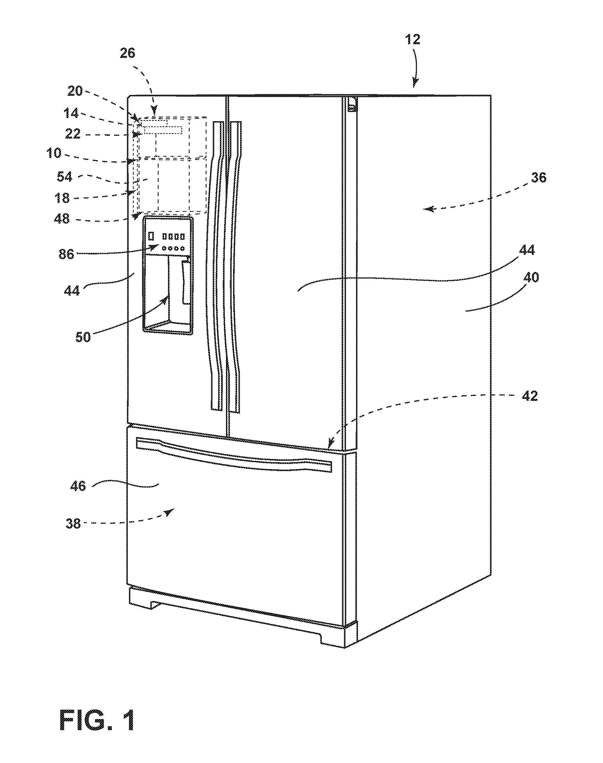
[0007] FIG. 1 is a front perspective view of a refrigerated appliance incorporating an icemaker;
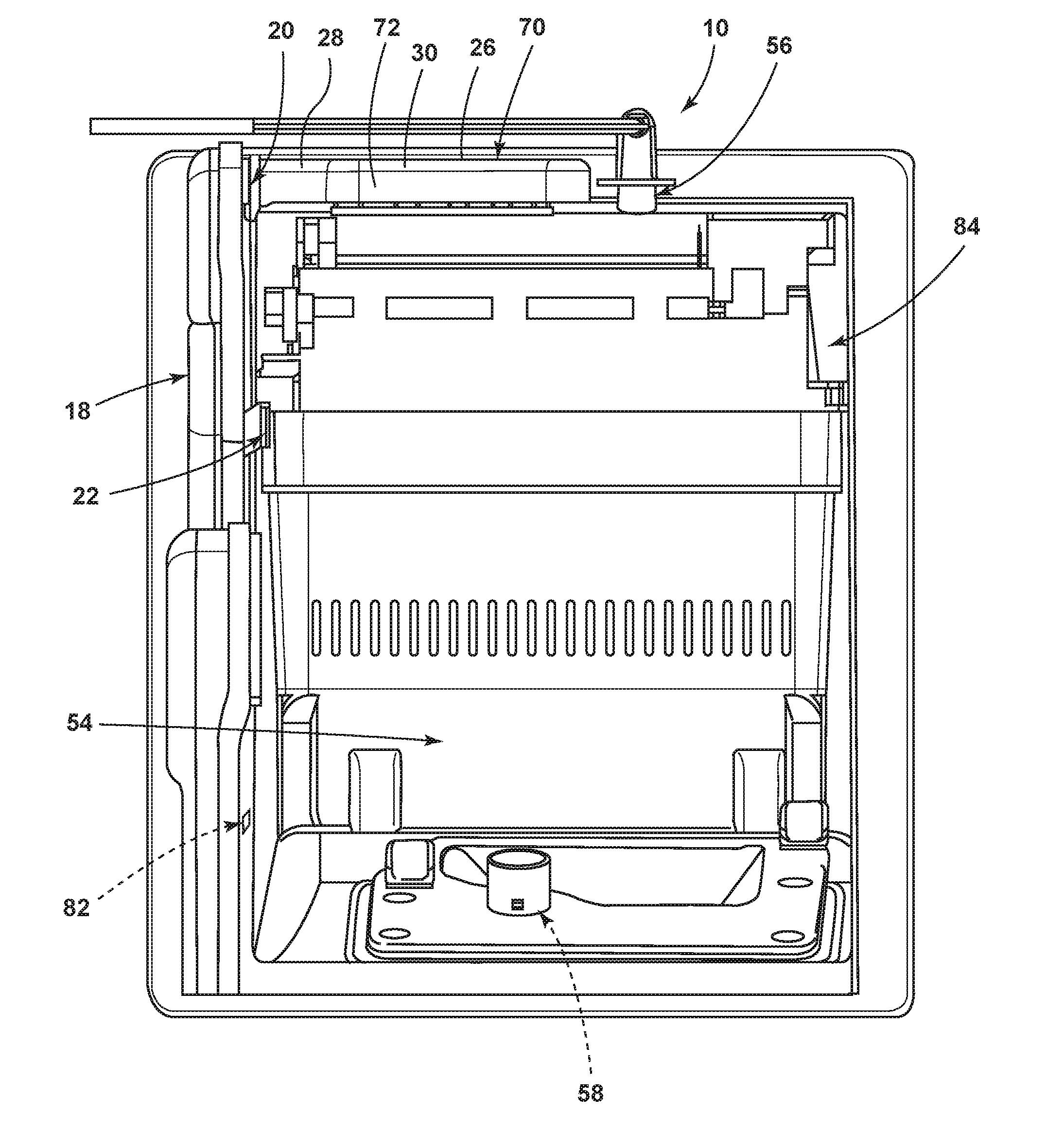
[0008] FIG. 2 is a side perspective view of an icemaker for a refrigerated appliance incorporating an upper baffle and a lower baffle, according to some examples;
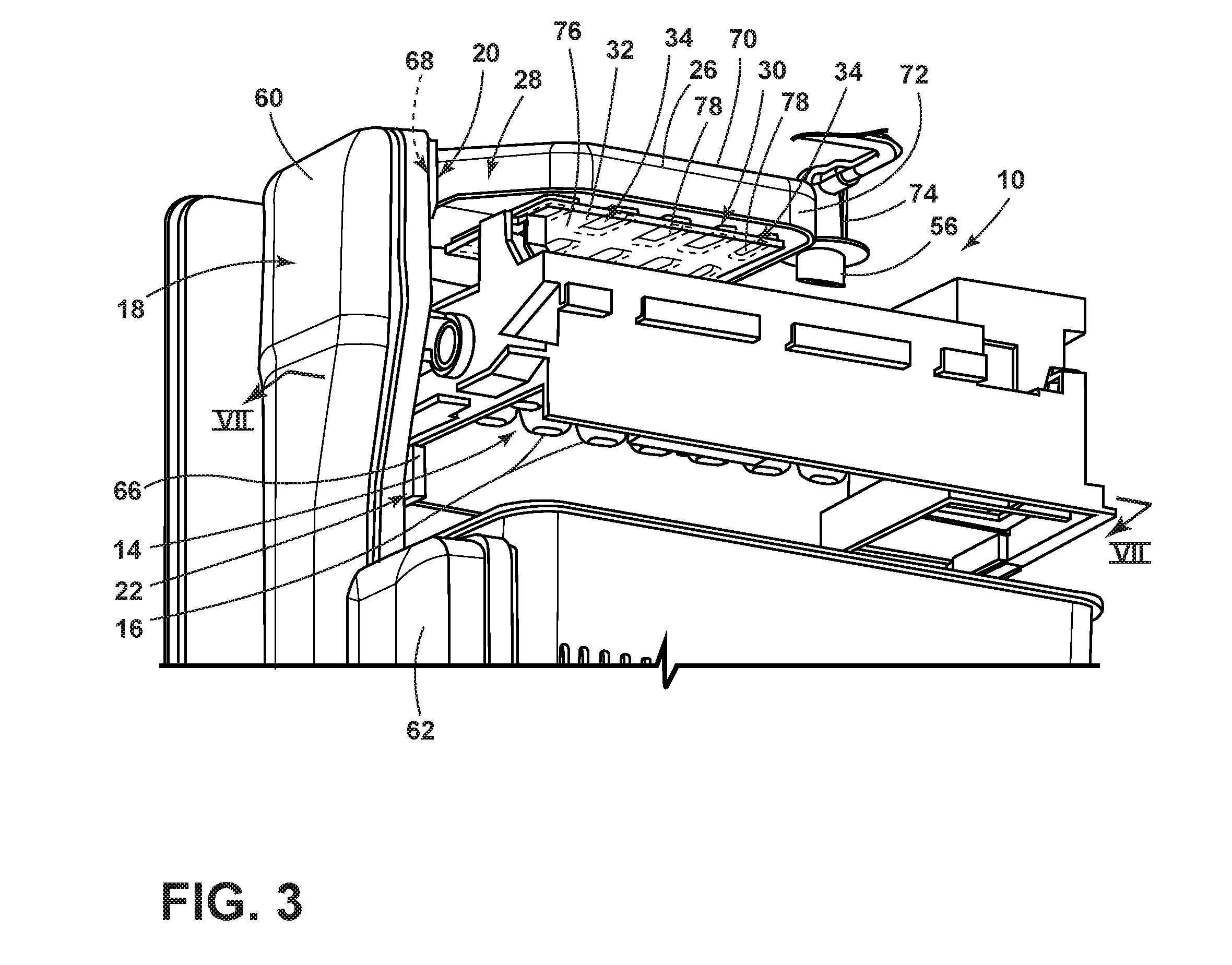
[0009] FIG. 3 is a bottom perspective view of the icemaker, according to some examples;
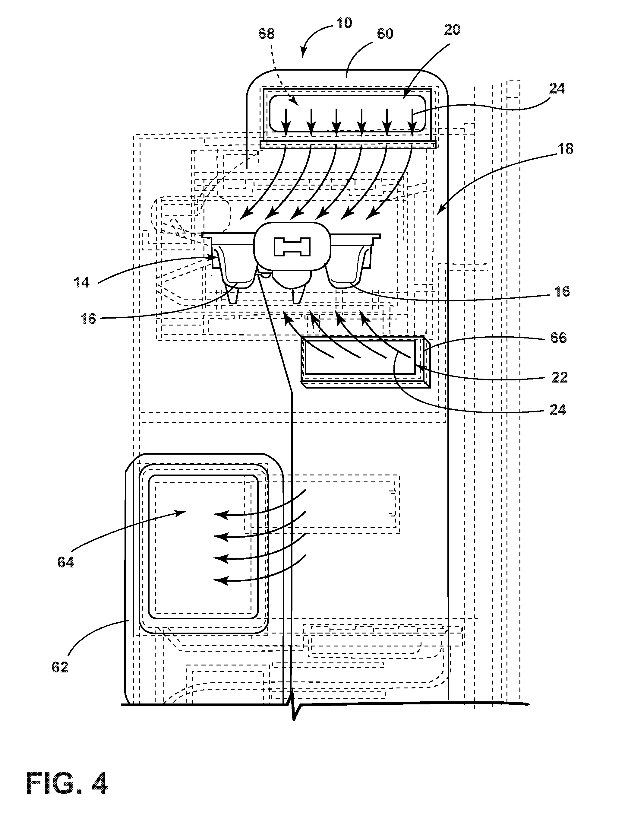
[0010] FIG. 4 is a side plan view of a duct system that supplies chilled air for the icemaker and an ice tray disposed between the upper baffle and the lower baffle, according to some examples;
[0011] FIG. 5A is a top plan view of the ice tray, according to some examples;
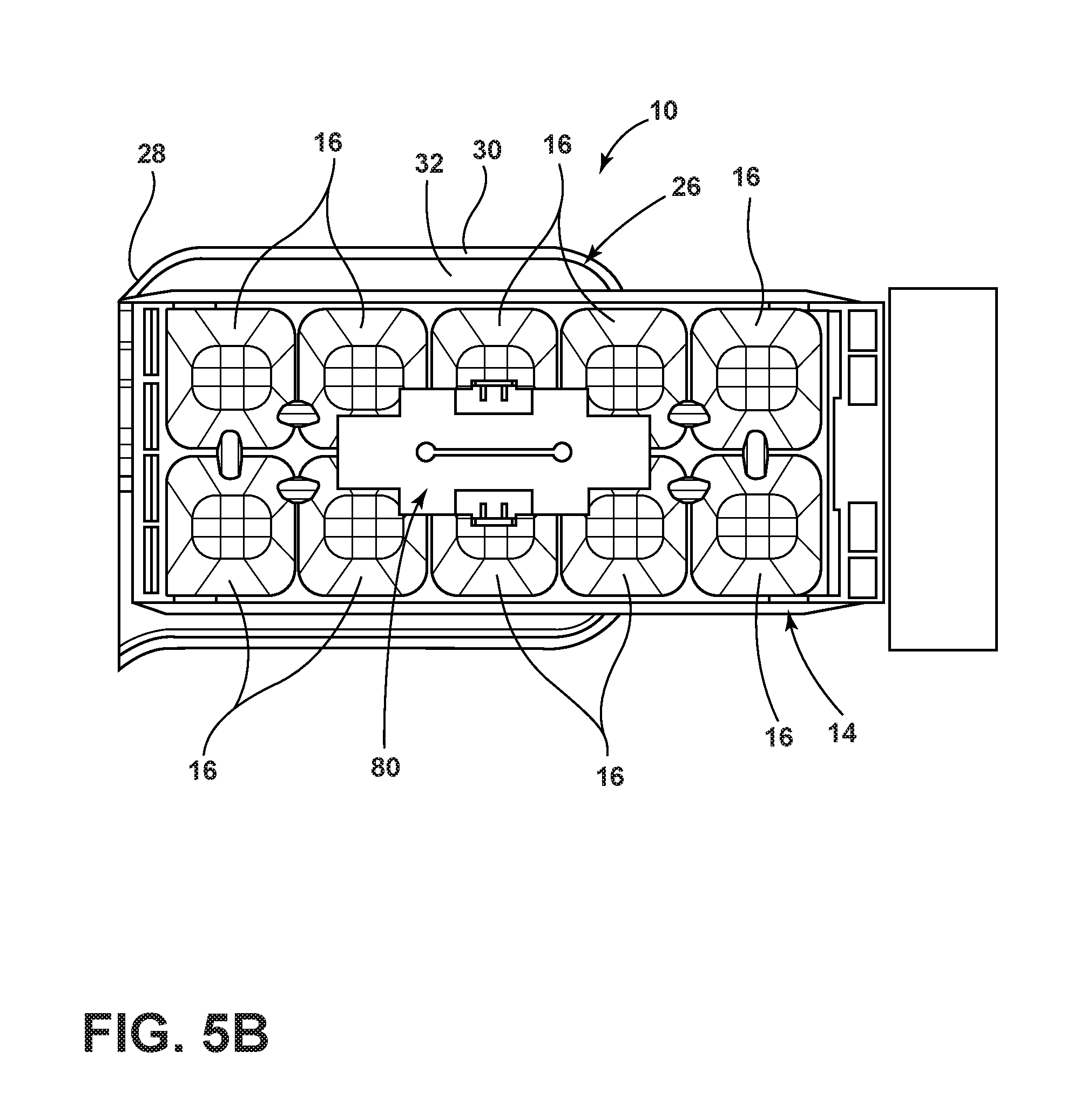
[0012] FIG. 5B is a bottom plan view of the ice tray, according to some examples;
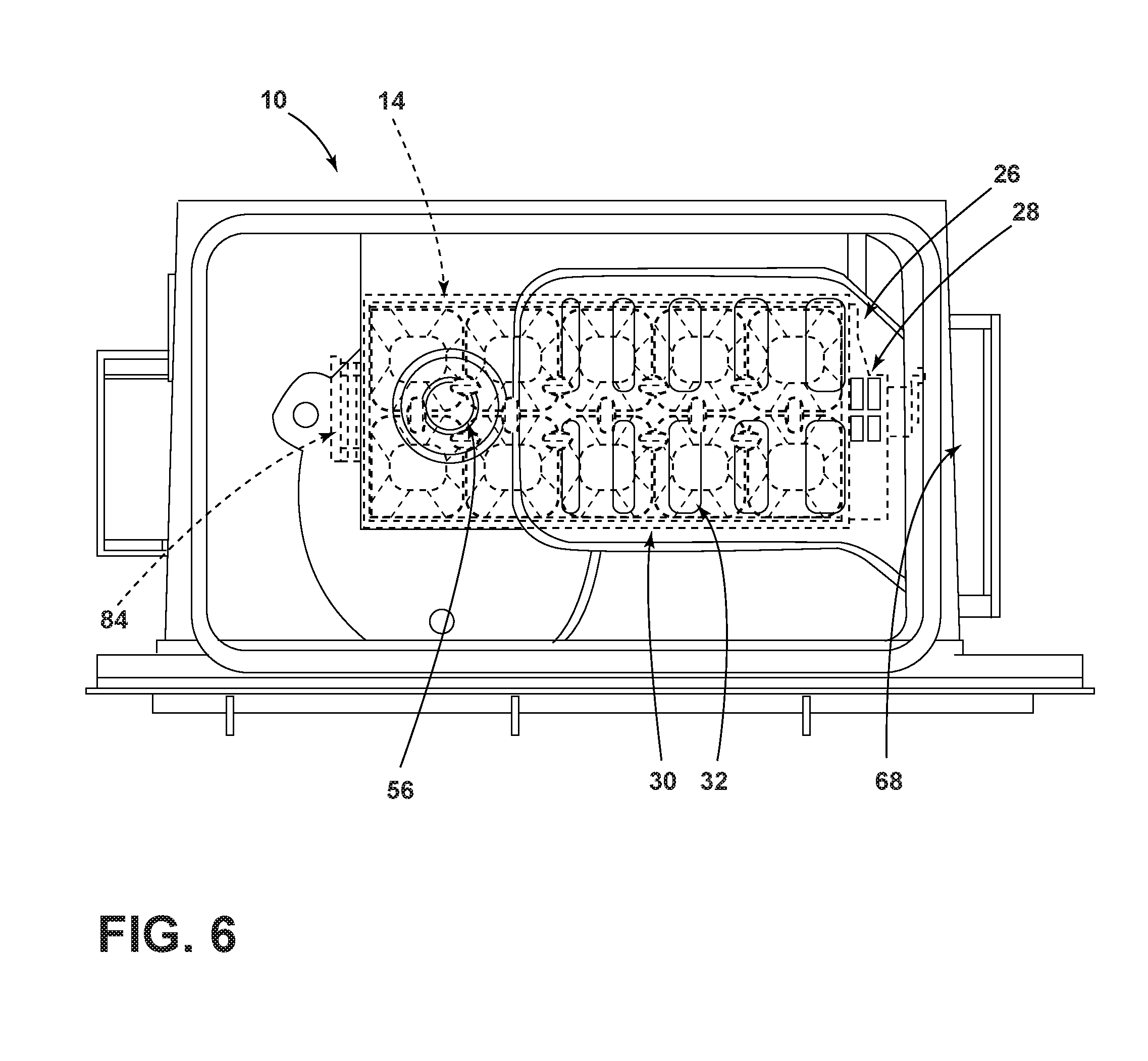
[0013] FIG. 6 is a top plan view of the deflector, according to some examples;
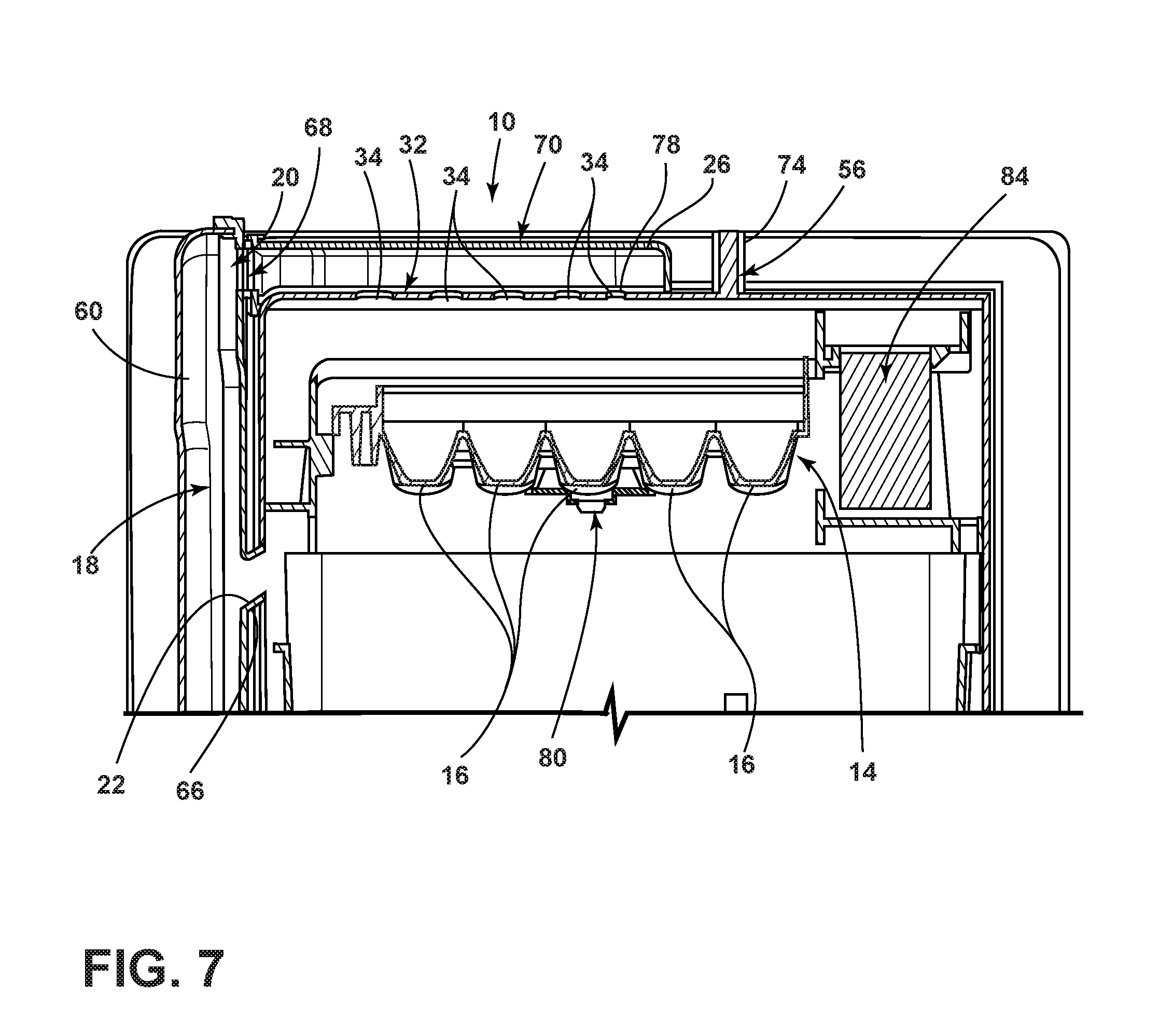
[0014] FIG. 7 is a cross-sectional view taken along the line VII-VII of FIG. 3 illustrating the icemaker according to some examples;
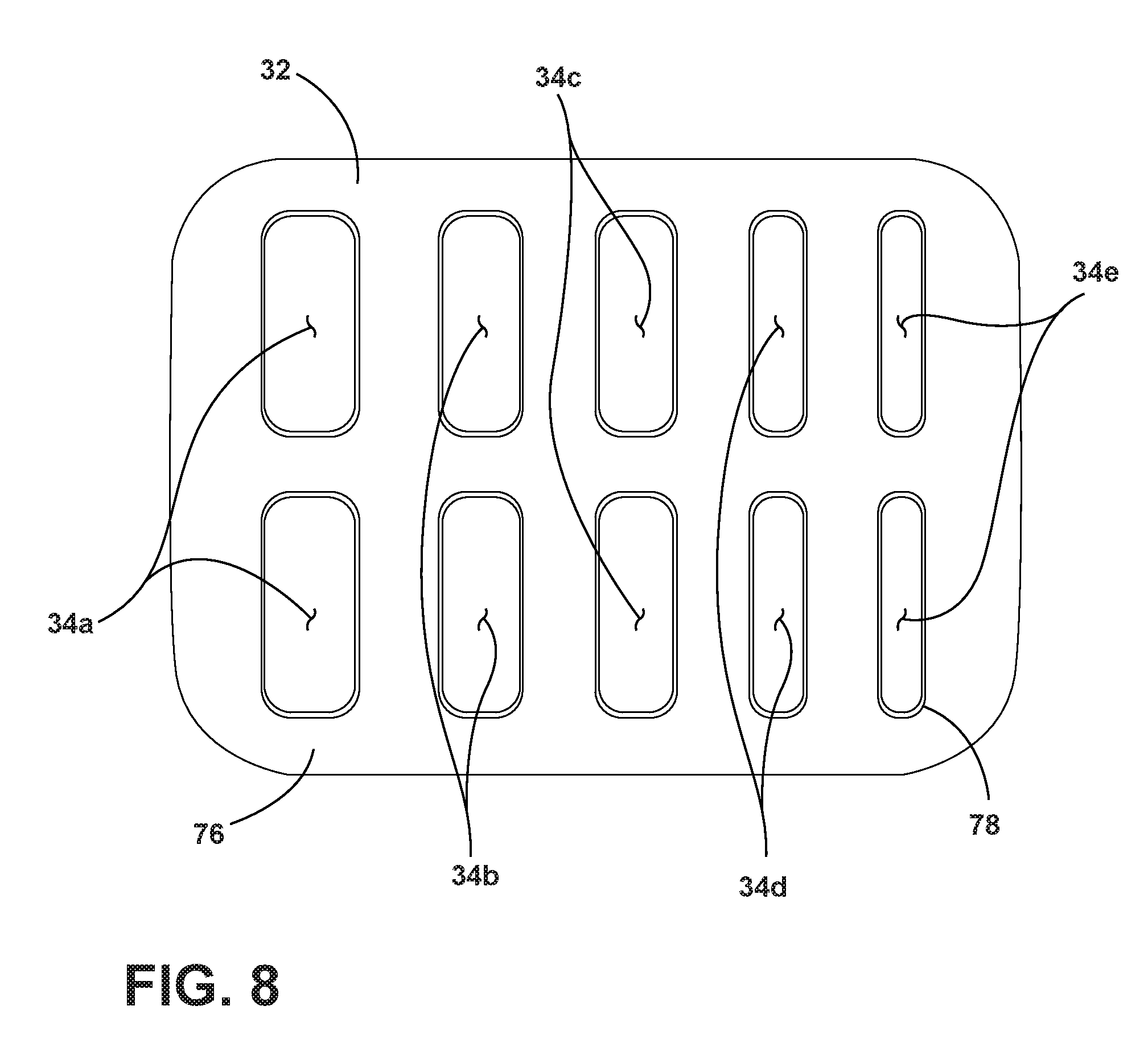
[0015] FIG. 8 is a top plan view of the diverter defining variously sized slots therealong, according to some examples;
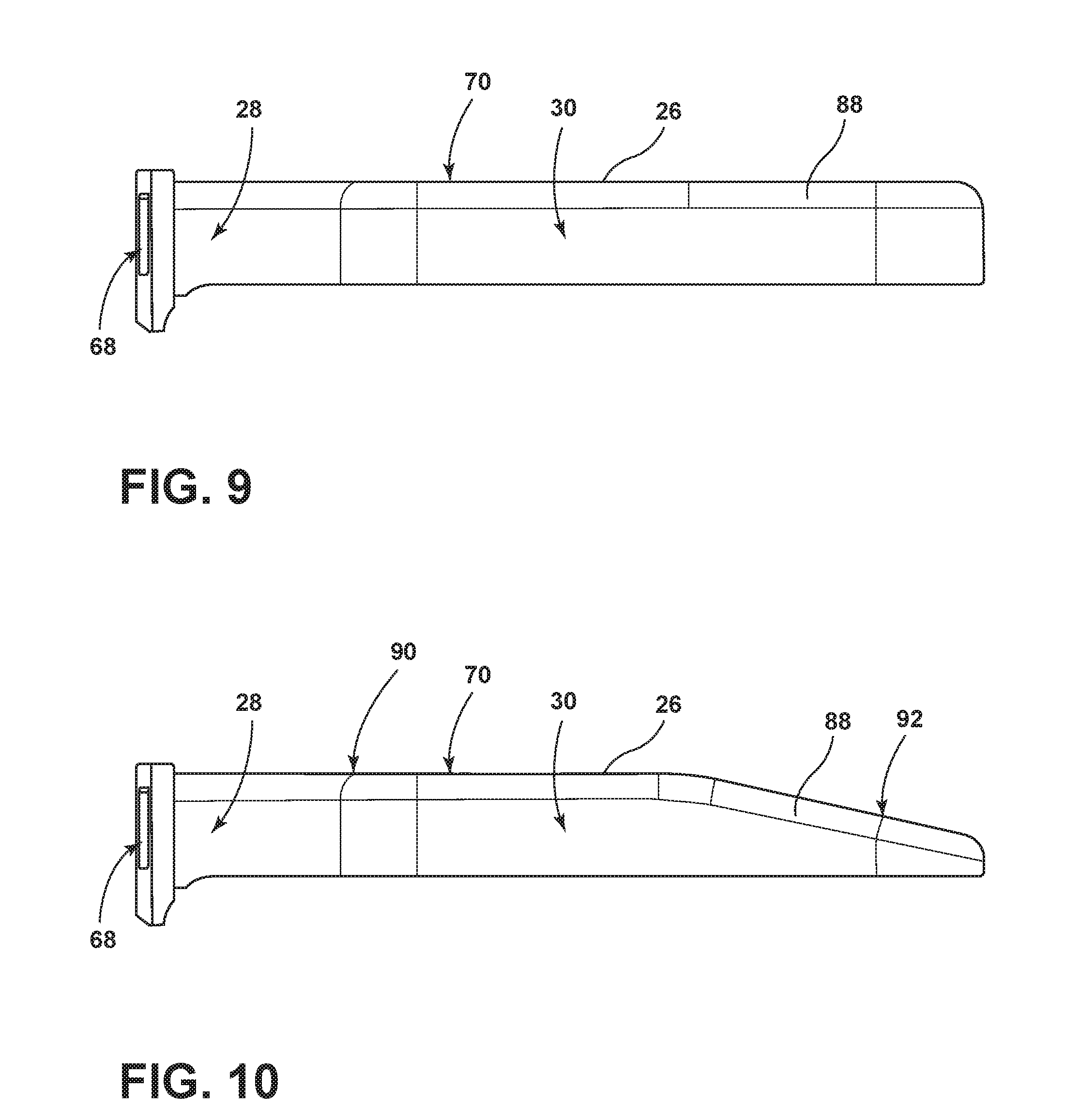
[0016] FIG. 9 is a side plan view of the deflector according to some examples; and
[0017] FIG. 10 is a side plan view of the deflector according to some examples.
DETAILED DESCRIPTION
[0018] For purposes of description herein, the terms "upper," "lower," "right," "left," "rear," "front," "vertical," "horizontal," and derivatives thereof shall relate to the invention as oriented in FIG. 1. However, it is to be understood that the invention may assume various alternative orientations, except where expressly specified to the contrary. It is also to be understood that the specific devices and processes illustrated in the attached drawings, and described in the following specification are simply exemplary examples of the inventive concepts defined in the appended claims. Hence, specific dimensions and other physical characteristics relating to the examples disclosed herein are not to be considered as limiting, unless the claims expressly state otherwise.
[0019] As required, detailed examples of the present invention are disclosed herein. However, it is to be understood that the disclosed examples are merely exemplary of the invention that may be embodied in various and alternative forms. The figures are not necessarily to a detailed design and some schematics may be exaggerated or minimized to show function overview. Therefore, specific structural and functional details disclosed herein are not to be interpreted as limiting, but merely as a representative basis for teaching one skilled in the art to variously employ the present invention.
[0020] In this document, relational terms, such as first and second, top and bottom, and the like, are used solely to distinguish one entity or action from another entity or action, without necessarily requiring or implying any actual such relationship or order between such entities or actions. The terms "comprises," "comprising," or any other variation thereof, are intended to cover a non-exclusive inclusion, such that a process, method, article, or apparatus that comprises a list of elements does not include only those elements but may include other elements not expressly listed or inherent to such process, method, article, or apparatus. An element preceded by "comprises . . . a" does not, without more constraints, preclude the existence of additional identical elements in the process, method, article, or apparatus that comprises the element.
[0021] As used herein, the term "and/or," when used in a list of two or more items, means that any one of the listed items can be employed by itself, or any combination of two or more of the listed items can be employed. For example, if a composition is described as containing components A, B, and/or C, the composition can contain A alone; B alone; C alone; A and B in combination; A and C in combination; B and C in combination; or A, B, and C in combination.
[0022] With reference to FIGS. 1-10, an icemaker 10 for a refrigerated appliance 12 is provided herein. The icemaker 10 includes an ice tray 14 having a plurality of ice-forming compartments 16. A duct system 18 has upper and lower baffles 20, 22. The upper baffle 20 directs chilled air 24 above the ice tray 14 and the lower baffle 22 directs the chilled air 24 below the ice tray 14. A deflector 26 is operably coupled with the upper baffle 20. The deflector 26 has a transition portion 28 offset from a body portion 30. A diverter 32 is disposed between the deflector 26 and the ice tray 14. The deflector 26 defines a plurality of variously sized slots 34 therein.
[0023] Referring to FIGS. 1 and 2, reference numeral 10 generally designates the refrigerated appliance 12 with the icemaker 10. The icemaker may be used as a stand-alone appliance or within another appliance, such as a refrigerator. The ice-making process may be induced, carried out, stopped, and the ice is harvested with little, or no, user input. FIG. 1 generally shows a refrigerator of the French-door bottom mount type, but it is understood that this disclosure could apply to any type of refrigerator, such as a side-by-side, two-door bottom mount, or a top-mount type refrigeration unit.
[0024] As shown in FIGS. 1 and 2, the refrigerated appliance 12 may have a refrigerated compartment 36 configured to refrigerate consumables and a freezer compartment 38 configured to freeze consumables during normal use. Accordingly, the refrigerated compartment 36 may be kept at a temperature above the freezing point of water and generally below a temperature of from about 35.degree. F. to about 50.degree. F., more typically below about 38.degree. F. and the freezer compartment 38 may be kept at a temperature below the freezing point of water.
[0025] In some instances, the refrigerated appliance 12 has a cabinet 40 and a liner within the cabinet 40 to define the refrigerated compartment 36 and the freezer compartment 38. A mullion 42 may separate the refrigerated compartment 36 and the freezer compartment 38.
[0026] The refrigerated appliance 12 may have one or more doors 44, 46 that provide selective access to the interior volume of the refrigerated appliance 12 where consumables may be stored. As shown, the refrigerated compartment doors are designated 44, and the freezer door is designated 46. It is appreciated that the refrigerated compartment 36 may only have one door 44.
[0027] The icemaker 10 may be positioned within the door 44 and in an icemaker receiving space 48 of the appliance to allow for delivery of ice through the door 44 in a dispensing area 50 on the exterior of the appliance. The dispensing area 50 may be at a location on the exterior below the level of an ice storage bin 54 to allow gravity to force the ice down an ice dispensing chute in the refrigerated appliance door 44. The chute extends from the storage bin 54 to the dispenser area 50 and ice may be pushed into the chute using an electrically power-driven auger 58.
[0028] The refrigerated appliance 12 may also have a water inlet that is fastened to and in fluid communication with a household supply of potable water. The water inlet may be fluidly engaged with one or more of a water filter, a water reservoir, and a refrigerated appliance water supply line. The water supply line may include one or more nozzles and one or more valves. The water supply line may supply water to one or more water outlets 56. For example, a first outlet may dispense water in the dispensing area and a second outlet 56 may dispense water into the ice tray 14. The refrigerated appliance 12 may also have a control board or controller that sends electrical signals to the one or more valves when prompted by a user through a user interface 86, which may be on the front face of a door 44, that water is desired or if an ice-making cycle is to begin.
[0029] The icemaker 10 may be located at an upper portion of the icemaker receiving space 48. The ice storage bin 54 may be located below the icemaker 10 such that as ice is harvested, the icemaker 10 uses gravity to transfer the ice from the icemaker 10 to the ice storage bin 54.
[0030] As shown in FIGS. 3 and 4, the refrigerated appliance 12 may also have one or more ducts that form the duct system 18. In some examples, the duct system 18 may include a supply duct 60 and a return duct 62. The supply duct 60 may be disposed in close proximity to the ice tray 14 to direct chilled air 24 at the tray and water disposed within the tray. The return duct 62 may be disposed in close proximity to the ice bin. Accordingly, the chilled air 24 may be directed toward the ice tray 14, circulated through the ice bin, and exit through a return vent 64 defined by the return duct 62. In some examples, the return vent 64 is proximate the ice bin.
[0031] In some examples, the supply duct 60 includes the upper baffle 20 and the lower baffle 22. The upper baffle 20 is disposed above the ice tray 14 and may direct the chilled air 24 in a downward and/or horizontal direction. The lower baffle 22 may include an upwardly directed rim section 66 that is configured to direct the chilled air 24 at a bottom side of the ice tray 14. Accordingly, chilled air 24 may be directed at two opposing sides of the ice tray 14, which may decrease the amount of time needed to freeze water in the trays during the ice-making process. In some examples, the rim section 66 may be an additional component that is operably coupled to the lower baffle 22. Alternatively, the rim section 66 may be integrally formed with the lower baffle 22 and/or the supply duct 60. Moreover, in some instances, the rim section 66 is configured to direct the chilled air 24 at the bottom side of the ice tray 14 with no obstacles between the rim section 66 and the ice tray 14.
[0032] The deflector 26 is operably coupled with the upper baffle 20 and is configured to redirect air from the upper baffle 20 towards various portions of the ice tray 14. Accordingly, the deflector 26 includes an entry portion 68 that is proximate the upper baffle 20. The deflector 26 further includes a top surface 70 and a peripheral portion 72 extending therefrom. As the chilled air 24 is directed outwardly from the upper baffle 20, the chilled air 24 is substantially maintained below the deflector 26. Moreover, the deflector 26 is configured to direct the chilled air 24 downwardly and towards the ice tray 14.
[0033] In some examples, the deflector 26 may be disposed over a portion of the ice tray 14. Or, in other words, the second water supply outlet 56 is disposed over the ice tray 14 on an opposing side of the deflector 26 from the upper baffle 20. A heater 74 is installed on the second water supply outlet 56. The heater 74 heats the outlet to prevent blockages thereof. The heater 74 may include an electric heating medium that generates heat upon receiving electric power or the like. The heater 74 heats the bottom portion of the outlet 56 before the water supply is operated so that the water can be easily disposed within the ice tray 14.
[0034] Referring to FIGS. 5A-6, the upper and lower baffles 20, 22 may be offset from the ice tray 14. Accordingly, the deflector 26 may have a transition portion 28 that directs air from the upper baffle 20 to the body portion 30 over the ice tray 14. The body portion 30 may be operably coupled with an air diverter 32 that directs the chilled air 24 within the body portion 30 through predefined slots 34 within the diverter 32.
[0035] Referring to FIGS. 3-7, the diverter 32 may include a base 76 that defines the plurality of slots 34. A border 78 may surround each of the plurality of slots 34. In some instances, the border 78 extends upwardly from the base 76 and encompasses each respective slot. Each slot defines an opening area through which the chilled air 24 is directed. In some examples, a first pair of slots 34a (FIG. 8) closest to the upper baffle 20 has a first opening area. An adjacently disposed second pair of slots 34b on an opposing side of the first pair of slots 34a from the upper baffle 20 has a second opening area that is smaller than the first opening area. Likewise, a third pair of slots 34c is disposed on opposing side of the second pair of slots 34b from the first pair of slots 34a and has a third opening area that is less than the second opening area. A fourth pair of slots 34d defines a fourth opening area and has a smaller opening area than the third area. Lastly, a fifth pair of slots 34e defines a fifth opening area that is less than the fourth area. It will be appreciated, however, that any of the slots 34a, 34b, 34c, 34d, 34e may have an opening area that is equal to any number, or all, of the remaining slots. Moreover, the slots 34a, 34b, 34c, 34d, 34e may be varied in any other pattern without departing from the scope of the present disclosure. Furthermore, in some instances, any and/or all of the slots 4a, 34b, 34c, 34d, 34e disposed on the diverter 32 may be of an equal size to one another without departing from the scope of the present disclosure.
[0036] In some instances, the fifth pair of slots 34e has a smaller opening area such that the chilled air 24 is directed therethrough at a higher pressure and/or velocity than the first pair of slots 34a. For example, the airflow velocity can be calculated by the following formula: air velocity=air flow/area of the duct. Accordingly, as the size of the slot is decreased, the airflow velocity is increased. The airflow may be increased to reach portions of the tray that extend beyond the diverter 32. Additionally, and/or alternatively, the airflow may be increased to decrease the amount of time before the chilled air 24 reaches the ice tray 14 to increase the efficiency of the water freezing process.
[0037] As illustrated in FIGS. 5A-6, the air diverter 32 may be disposed over a portion of the ice tray 14. However, it will be appreciated that in other examples the diverter 32 may be disposed over the whole ice tray 14 without departing from the teachings provided herein. As illustrated, the ice tray 14 includes five longitudinally aligned compartments 16 in which ice may be formed and the diverter 32 extends over four of the five longitudinally aligned compartments 16. As the chilled air 24 is directed from the upper baffle 20 and through the deflector 26 and the slots 34 in the diverter 32, the chilled air 24 is forced away from the duct system 18 causing a first end portion of the ice tray 14 that is proximate the duct system 18 and a second end portion of the ice tray 14 on an opposing side of the ice tray 14 to be contacted by the chilled air 24.
[0038] In some examples, the ice tray 14 may incorporate a temperature sensor 80, for example, a thermistor or other temperature-sensing element positioned beneath the ice tray 14 in close proximity to the compartments 16 so as to sense a temperature of that volume. Temperatures above the freezing point generally indicate incomplete freezing of the cubes, whereas temperatures below freezing indicate that the cube has frozen and no additional phase change is occurring. As provided herein, the first end portion of the ice tray 14 may be proximate the duct system 18 while the second end portion of the ice tray 14 may be disposed further from the duct system 18. The temperature sensor 80 may be disposed outwardly of a portion of the ice tray 14 that is directly contacted by the chilled air as a temperature of the non-directly contacted portions of the ice tray. It will be appreciated, however, that the temperature sensor may be disposed in any practicable location without departing from the scope of the present disclosure.
[0039] In operation, the icemaker 10 may begin an ice-making cycle when a controller in electrical communication with an ice level sensor 82 (FIG. 2), ice level input measuring system and/or device detects an actual ice level is below a predetermined ice level. To begin the ice-making process, the icemaker 10 checks whether the ice tray 14 is in the home position, such as an upright or horizontal position. If the ice tray 14 is not in its home position, the controller may send a signal to a motor 84 to rotate the ice tray 14 back to its home position. Once the ice tray 14 is determined to be in its home position, the controller determines whether any previous harvests were completed. If the previous harvest was completed, the controller may send an electrical signal to open a valve in fluid communication with the icemaker 10. Either after a predetermined amount of valve open time or when the controller senses that a predetermined amount of water has been delivered to the ice tray 14, a signal will be sent by the controller to the valve to close the valve. The predetermined amount of water may be based on the size of the ice tray 14 and/or the speed at which a user would like ice and may be set at the point of manufacture or based on an input from a user into a user interface 86 (FIG. 1). The water outlet 56 may be positioned above the ice tray 14, such that the water falls with the force of gravity into the ice tray 14.
[0040] After the ice tray 14 is filled, or if the controller determines that the previous harvest was incomplete, the freeze timer may be started, and the chilled air 24 at a temperature below the freezing point of water is forced through the supply duct 60 of the duct system 18 of the icemaker. The air may be forced by one or more fan or any other method of moving air known in the art. As provided herein, the duct system 18 includes an upper baffle 20 that directs air from the duct system 18 above the ice tray 14 and a lower baffle 22 that directs air at a bottom side of the ice tray 14.
[0041] During the freezing process, the controller may determine if a refrigerated appliance door 44 has been opened. If the door 44 is determined to be open at any time, the freeze timer is paused until the door 44 is closed. After some time, substantially all or all of the water will be frozen into ice. The controller may detect this by using the thermistor or another sensor. During the freezing process, the controller also may determine if the temperature of the ice tray 14 or the temperature within the ice compartment 16 is above a certain temperature for a certain amount of time. This temperature may be between 20.degree. F. and 30.degree. F., and more typically from about 22.degree. F. to about 28.degree. F. If the controller determines that the temperature was above the specified temperature for longer than the specified time, the freeze timer may reset.
[0042] When the freeze timer reaches a predetermined time and/or when the thermistor sends an electrical signal to the controller that a predetermined temperature of the ice tray 14 is met, the controller may read this as the water is frozen, and it may begin the harvesting process. Consequently, the controller will send a signal to the motor 84 to begin rotating. As the motor 84 begins rotating, the ice tray 14, which is rotationally engaged with the motor 84 at the second end portion, rotates with it. The ice tray 14 may begin at a substantially horizontal position. The motor 84 rotates the ice tray 14 to a predetermined angle. When the motor 84 and tray reach the predetermined angle, the first end portion of the ice tray 14 may be prevented from rotating any further by a bracket stop. With the first end portion held in place by the bracket stop, the motor 84 continues to rotate the ice tray 14 to a second predetermined angle. By continuing to rotate the second end portion, a twist is induced in the ice tray 14. The twist in the ice tray 14 induces an internal stress between the ice and the ice tray 14, which separates the ice from the ice tray 14. The twist angle may be any angle sufficient to break the ice loose from the ice tray 14. After the rotation is complete, the motor 84 returns to its home position. If the controller determines that the ice tray 14 reached the harvest position and back to home position, the cycle may begin again.
[0043] Referring to FIGS. 9 and 10, as provided herein, the deflector 26 includes the body portion 30 and the transition portion 28. In some examples, the deflector 26 may be integrally formed with a portion of the duct system 18. The body portion 30 is disposed over the ice tray 14 while the transition portion 28 may be offset from the body portion 30 and configured to couple to the duct system 18 around the upper baffle 20. The entry portion 68 of the deflector 26 may surround the upper baffle 20. In other examples, the entry portion 68 may partially surround or otherwise be operably coupled with the upper baffle 20.
[0044] With further reference to FIGS. 9 and 10, the body portion 30 of the deflector 26 may be of any practicable geometry without departing from the scope of the present disclosure. For example, as illustrated in FIG. 9, the body portion 30 of the deflector 26 may have a linear top surface 70. A radiused portion 88 may couple the body portion 30 to the peripheral portion 72. Alternatively, as illustrated in FIG. 10, the top surface 70 of the body portion 30 may have a first linear section 90 and a second section 92 that is angled downwardly from the first section 90. Like the example illustrated in FIG. 9, the radiused portion 88 couples the top surface 70 to the peripheral portion 72.
[0045] A variety of advantages may be derived from the use of the present disclosure. For example, use of the icemaker provided herein may decrease the freezing time for making ice within a refrigerated appliance. The use of the deflector provided herein may assist in directing chilled air towards the ice tray to further assist in the ice-making process. Furthermore, a diverter may be used in conjunction with the deflector for directing air in desired locations at various pressures based on the slot sizing disposed within the diverter. The ice-making assembly provided herein may be more efficient and/or cheaper to manufacture than ice-making systems currently available.
[0046] It will be understood by one having ordinary skill in the art that construction of the described invention and other components is not limited to any specific material. Other exemplary examples of the invention disclosed herein may be formed from a wide variety of materials, unless described otherwise herein.
[0047] For purposes of this disclosure, the term "coupled" (in all of its forms, couple, coupling, coupled, etc.) generally means the joining of two components (electrical or mechanical) directly or indirectly to one another. Such joining may be stationary in nature or movable in nature. Such joining may be achieved with the two components (electrical or mechanical) and any additional intermediate members being integrally formed as a single unitary body with one another or with the two components. Such joining may be permanent in nature or may be removable or releasable in nature unless otherwise stated.
[0048] Furthermore, any arrangement of components to achieve the same functionality is effectively "associated" such that the desired functionality is achieved. Hence, any two components herein combined to achieve a particular functionality can be seen as "associated with" each other such that the desired functionality is achieved, irrespective of architectures or intermedial components. Likewise, any two components so associated can also be viewed as being "operably connected" or "operably coupled" to each other to achieve the desired functionality, and any two components capable of being so associated can also be viewed as being "operably coupleable" to each other to achieve the desired functionality. Some examples of operably coupleable include, but are not limited to, physically mateable and/or physically interacting components and/or wirelessly interactable and/or wirelessly interacting components and/or logically interacting and/or logically interactable components. Furthermore, it will be understood that a component preceding the term "of the" may be disposed at any practicable location (e.g., on, within, and/or externally disposed from the appliance) such that the component may function in any manner described herein.
[0049] It is also important to note that the construction and arrangement of the elements of the invention as shown in the exemplary examples is illustrative only. Although only a few examples of the present innovations have been described in detail in this disclosure, those skilled in the art who review this disclosure will readily appreciate that many modifications are possible (e.g., variations in sizes, dimensions, structures, shapes and proportions of the various elements, values of parameters, mounting arrangements, use of materials, colors, orientations, etc.) without materially departing from the novel teachings and advantages of the subject matter recited. For example, elements shown as integrally formed may be constructed of multiple parts or elements shown as multiple parts may be integrally formed, the operation of the interfaces may be reversed or otherwise varied, the length or width of the structures and/or members or connectors or other elements of the system may be varied, the nature or number of adjustment positions provided between the elements may be varied. It should be noted that the elements and/or assemblies of the system might be constructed from any of a wide variety of materials that provide sufficient strength or durability, in any of a wide variety of colors, textures, and combinations. Accordingly, all such modifications are intended to be included within the scope of the present innovations. Other substitutions, modifications, changes, and omissions may be made in the design, operating conditions, and arrangement of the desired and other exemplary examples without departing from the spirit of the present innovations.
[0050] It will be understood that any described processes or steps within described processes may be combined with other disclosed processes or steps to form structures within the scope of the present invention. The exemplary structures and processes disclosed herein are for illustrative purposes and are not to be construed as limiting.
[0051] It is also to be understood that variations and modifications can be made on the aforementioned structures and methods without departing from the concepts of the present invention, and further it is to be understood that such concepts are intended to be covered by the following claims unless these claims by their language expressly state otherwise.
* * * * *
D00000
D00001
D00002
D00003
D00004
D00005
D00006
D00007
D00008
D00009
D00010
XML
uspto.report is an independent third-party trademark research tool that is not affiliated, endorsed, or sponsored by the United States Patent and Trademark Office (USPTO) or any other governmental organization. The information provided by uspto.report is based on publicly available data at the time of writing and is intended for informational purposes only.
While we strive to provide accurate and up-to-date information, we do not guarantee the accuracy, completeness, reliability, or suitability of the information displayed on this site. The use of this site is at your own risk. Any reliance you place on such information is therefore strictly at your own risk.
All official trademark data, including owner information, should be verified by visiting the official USPTO website at www.uspto.gov. This site is not intended to replace professional legal advice and should not be used as a substitute for consulting with a legal professional who is knowledgeable about trademark law.