System And Method For Operating A Portable Air Heater
Huggins; Mark ; et al.
U.S. patent application number 16/182712 was filed with the patent office on 2019-05-16 for system and method for operating a portable air heater. The applicant listed for this patent is TTI (MACAO COMMERCIAL OFFSHORE) LIMITED. Invention is credited to Mark Huggins, Devin E. Kilarski, Scott P. Kippes, Benjamin M. Williams.
| Application Number | 20190145663 16/182712 |
| Document ID | / |
| Family ID | 66431986 |
| Filed Date | 2019-05-16 |


View All Diagrams
| United States Patent Application | 20190145663 |
| Kind Code | A1 |
| Huggins; Mark ; et al. | May 16, 2019 |
SYSTEM AND METHOD FOR OPERATING A PORTABLE AIR HEATER
Abstract
A portable forced air heater including a housing, a heating element located within the housing, a sensor configured to sense a characteristic of the portable heater, a communications device configured to communicate with an external device, and a controller having an electrical processor and memory. The controller is configured to receive, from the sensor, the characteristic of the portable heater, and output, via the communications device, a signal indicative of the characteristic of the portable heater to the external device.
| Inventors: | Huggins; Mark; (Anderson, SC) ; Williams; Benjamin M.; (Simpsonville, SC) ; Kippes; Scott P.; (Piedmont, SC) ; Kilarski; Devin E.; (Greenville, SC) | ||||||||||
| Applicant: |
|
||||||||||
|---|---|---|---|---|---|---|---|---|---|---|---|
| Family ID: | 66431986 | ||||||||||
| Appl. No.: | 16/182712 | ||||||||||
| Filed: | November 7, 2018 |
Related U.S. Patent Documents
| Application Number | Filing Date | Patent Number | ||
|---|---|---|---|---|
| 62584432 | Nov 10, 2017 | |||
| Current U.S. Class: | 392/365 |
| Current CPC Class: | F24H 9/2085 20130101; F24H 2240/01 20130101; F24H 3/0417 20130101; F24H 9/2071 20130101; H05B 3/00 20130101; F24H 3/0488 20130101; F24H 3/025 20130101; G05D 23/19 20130101; F24H 3/022 20130101 |
| International Class: | F24H 9/20 20060101 F24H009/20; F24H 3/02 20060101 F24H003/02 |
Claims
1. A portable forced air heater comprising: a housing; a heating element located within the housing; a sensor configured to sense a characteristic of the portable heater; a communications device configured to communicate with an external device; and a controller having an electrical processor and memory, the controller configured to receive, from the sensor, the characteristic of the portable heater, and output, via the communications device, a signal indicative of the characteristic of the portable heater to the external device.
2. The portable heater of claim 1, further comprising a battery receptacle located on the housing, the battery receptacle configured to receive a rechargeable battery pack.
3. The portable heater of claim 2, wherein the controller receives power from the rechargeable battery pack.
4. The portable heater of claim 2, wherein the rechargeable battery pack is used in conjunction with a power tool when removed from the battery receptacle.
5. The portable heater of claim 1, wherein the external device is at least one selected from a group consisting of an external computer, a smartphone, a tablet, a smart watch, and a server.
6. The portable heater of claim 1, wherein the characteristic is at least one selected from a group consisting of a fuel level, a battery capacity, a temperature, an oxygen level, and an angle.
7. The portable heater of claim 1, wherein the housing includes an accessory component, wherein the accessory component is at least one selected from a group consisting of a light source, a speaker, a thermostat, a Universal Serial Bus (USB) output, an alternating-current (AC) receptacle, a battery charger, a fluid pump, a wireless-connectivity hub, and an insect repellant device.
8. A portable forced air heater comprising: a housing; a heating element located within the housing; a communications device configured to communicate with an external device; and a controller having an electrical processor and memory, the controller configured to receive from the external device, via the communications device, a control signal, and control a component of the portable forced air heater according to the control signal.
9. The portable forced air heater of claim 8, wherein the component is at least one selected from a group consisting of a fan, the heating element, an oscillation motor, a light source, a speaker, a thermostat, a Universal Serial Bus (USB) output, an alternating-current (AC) receptacle, a battery charger, a fluid pump, a wireless-connectivity hub, and an insect repellant device.
10. The portable heater of claim 8, further comprising a battery receptacle located on the housing, the battery receptacle configured to receive a rechargeable battery pack.
11. The portable heater of claim 10, wherein the controller receives power from the rechargeable battery pack.
12. The portable heater of claim 10, wherein the rechargeable battery pack is used in conjunction with a power tool when removed from the battery receptacle.
13. The portable heater of claim 8, wherein the external device is at least one selected from a group consisting of an external computer, a smartphone, a tablet, a smart watch, and a server.
14. The portable heater of claim 8, wherein the housing includes an accessory component, wherein the accessory component is at least one selected from a group consisting of a light source, a speaker, a thermostat, a Universal Serial Bus (USB) output, an alternating-current (AC) receptacle, a battery charger, a fluid pump, a wireless-connectivity hub, and an insect repellant device.
15. The portable heater of claim 8, wherein the control signal relates to a temperature setting of the portable forced air heater.
16. A method of operating a portable forced air heater including a housing and a heating element located within the housing, the method comprising: sensing, via a sensor, a characteristic of the portable forced air heater; analyzing, via a controller having an electronic processor, the characteristic; and outputting, via a communications device, a signal indicative of the characteristic to an external device.
17. The method of claim 16, wherein the external device is at least one selected from a group consisting of an external computer, a smartphone, a tablet, a smart watch, and a server.
18. The method of claim 16, wherein the characteristic is at least one selected from a group consisting of a fuel level, a battery capacity, a temperature, an oxygen level, and an angle.
19. A method of operating a portable forced air heater including a housing and a heating element located within the housing, the method comprising: receiving from an external device, via a communications device, a control signal; and controlling, via a controller having an electronic processor, a component of the portable forced air heater based on the control signal.
20. The method of claim 19, wherein the external device is at least one selected from a group consisting of an external computer, a smartphone, a tablet, a smart watch, and a server.
21. The method of claim 19, wherein the control signal relates to a temperature setting of the portable forced air heater.
Description
RELATED APPLICATION
[0001] This application claims the benefit to U.S. Provisional Patent Application No. 62/584,432, filed on Nov. 10, 2017, the entire contents of which are incorporated herein by reference.
FIELD
[0002] Embodiments relate to forced air heaters, and more specifically, to portable forced air heaters.
SUMMARY
[0003] One embodiment provides a portable forced air heater including a housing, a heating element located within the housing, a sensor configured to sense a characteristic of the portable heater, a communications device configured to communicate with an external device, and a controller having an electrical processor and memory. The controller is configured to receive, from the sensor, the characteristic of the portable heater, and output, via the communications device, a signal indicative of the characteristic of the portable heater to the external device.
[0004] Another embodiment provides a portable forced air heater a housing, a heating element located within the housing, a communications device configured to communicate with an external device, and a controller having an electrical processor and memory. The controller is configured to receive from the external device, via the communications device, a control signal, and control a component of the portable forced air heater according to the control signal.
[0005] Another embodiment provides a method of operating a portable forced air heater including a housing and a heating element located within the housing. The method including sensing, via a sensor, a characteristic of the portable forced air heater. The method further including analyzing, via a controller having an electronic processor, the characteristic. The method further including outputting, via a communications device, a signal indicative of the characteristic to an external device.
[0006] Another embodiment provides a method of operating a portable forced air heater including a housing and a heating element located within the housing. The method including receiving from an external device, via a communications device, a control signal. The method further including controlling, via a controller having an electronic processor, a component of the portable forced air heater based on the control signal.
[0007] Other aspects of the application will become apparent by consideration of the detailed description and accompanying drawings.
BRIEF DESCRIPTION OF THE DRAWINGS
[0008] FIG. 1 is a front perspective view of a portable heater according to some embodiments.
[0009] FIG. 2 is a rear perspective view of the portable heater of FIG. 1 according to some embodiments.
[0010] FIG. 3 is a cross-sectional perspective view of the portable heater of FIG. 1, taken along line 3 of FIG. 1 according to some embodiments.
[0011] FIG. 4 is a rear elevation view of the portable heater of FIG. 1, depicting the portable heater having a battery pack removed according to some embodiments.
[0012] FIG. 5 is a rear elevation view of the portable heater of FIG. 1, depicting the portable heater having a battery pack coupled thereto according to some embodiments.
[0013] FIG. 6 is a front perspective view of a portable heater according to some embodiments.
[0014] FIG. 7 is a rear perspective view of the portable heater of FIG. 6 according to some embodiments.
[0015] FIG. 8 is a side elevation view of a portable heater according to some embodiments.
[0016] FIG. 9 is a block diagram of a control system of the portable heater according to some embodiments.
[0017] FIG. 10 is a flow chart illustrating an operation of a portable heater according to some embodiments.
[0018] FIG. 11 is a display of an external device for use with a portable heater according to some embodiments.
[0019] FIG. 12 is a flow chart illustrating an operation of a portable heater according to some embodiments.
[0020] FIG. 13 is a display of an external device for use with a portable heater according to some embodiments.
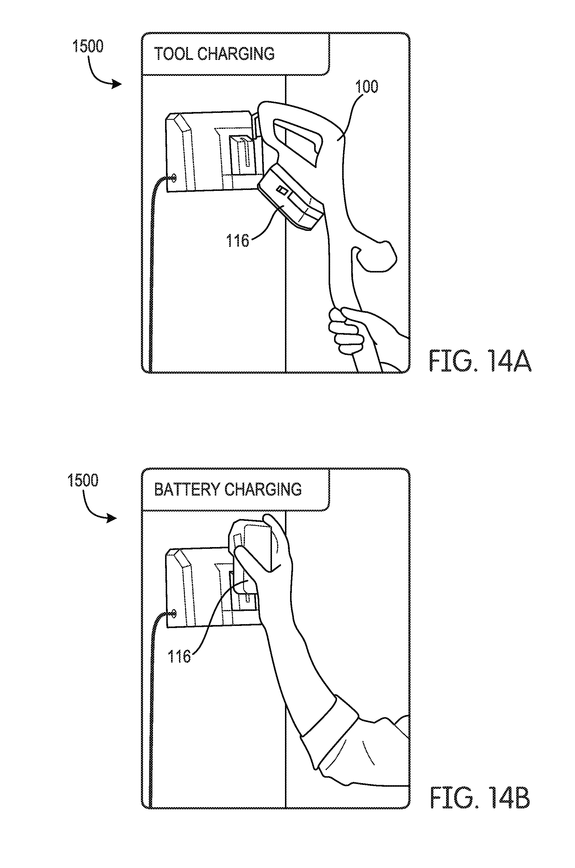
[0021] FIGS. 14A and 14B are front views of a battery charger of the portable heater according to some embodiments.
DETAILED DESCRIPTION
[0022] Before any embodiments of the application are explained in detail, it is to be understood that the application is not limited in its application to the details of construction and the arrangement of components set forth in the following description or illustrated in the following drawings. The application is capable of other embodiments and of being practiced or of being carried out in various ways.
[0023] FIG. 1 illustrates a heater 100 according to some embodiments. In some embodiments, heater 100 is portable. Furthermore, in some embodiments, the heater 100 is a forced air heater. Although illustrated as a portable forced heater, in other embodiments, the heater 100 is an oscillating heater. In some embodiments, the oscillating heater includes an oscillation motor configured to rotate, or oscillate, a heating element.
[0024] The heater 100 includes a housing 102 having a handle 112 configured to be grasped by an operator to maneuver the heater 100, and a base 106 coupled to the housing 102. The base 106 may include a support bar 110, a control panel 114, and a fuel inlet 126 selectively attachable to a hose 108, the hose 108 being in fluid communication with a fuel source (for example, propane, butane, etc.). In other embodiments, the fuel source is in direct fluid communication with the fuel inlet 126.
[0025] Located within housing 102 is a heating element (for example, a combustion chamber 138 (FIG. 3)). A cylinder 104 may be disposed within the housing 102 and defines the combustion chamber 138 (FIG. 3) configured to burn an air/fuel mixture to produce heat. In some embodiments, in addition to or in lieu of a combustion chamber 138, the heater 100 includes an electric heating element (for example, one or more resistive heating elements).
[0026] The heater 100 is configured to receive a battery pack 116 (FIG. 2) at the base 106. The battery pack 116 is a removable and rechargeable battery pack and may include one or more battery cells. In some embodiments, the battery pack 116 is an 18-volt battery pack having one or more lithium-ion battery cells. In other embodiments, the battery pack 116 may include fewer or more battery cells such that the battery pack 116 is a 12-volt battery pack, a 14.4-volt battery pack, or the like. Additionally or alternatively, the battery cells may have chemistries other than lithium-ion such as, for example, nickel-cadmium, nickel metal-hydride, or the like. In some embodiments, the battery pack 116 may be removed from the heater 100 and used in conjunction with other devices (for example, power tools (including, but not limited to, a drill, a driver, and a saw), lawn/garden equipment (including, but not limited to, a blower, a weed whacker, a hedger, and a lawn mower).
[0027] FIGS. 2 and 4-5 illustrate a power port 118 disposed in a rearward portion of the base 106. In other embodiments, the power port 118 may be disposed in one or more side portions of the base 106, and the heater 100 may alternatively include two or more power ports 118 power sources. Power port 118 includes battery receptacle 128 physically and electrically attachable to the battery pack 116. In some embodiments, the power port 118 additionally or alternatively includes an AC power receptacle 130 configured to receive an AC power source. In such embodiments, the heater 100 may be powered at least by one of a DC power source (for example, the battery pack 116) or an AC power source (for example, an AC power plug). In such embodiments, the battery receptacle 128 and the AC power receptacle 130 are combined into a single power port 118.
[0028] As illustrated in FIGS. 4-5, in some embodiments, the power port 118 is configured such that only one of the battery pack 116 and the AC power source may be connected to the heater 100 at one time. For example, when the battery pack 116 is inserted into the battery receptacle 128, the AC power receptacle 130 is obstructed by the battery pack 116 such that the AC power source may not be inserted into AC power receptacle 130. Likewise, when the AC power source is inserted into the AC power receptacle 130, the battery receptacle 128 is obstructed such that the battery pack 116 may not be inserted into the battery receptacle 128.
[0029] With reference to FIG. 3, in some embodiments the heater 100 includes a fan 110 and thermostat 122 disposed inside the combustion chamber 138. The thermostat 122 acts as a switch that opens when the heater 100 exceeds a predetermined temperature. In such embodiments, a controller (for example, controller 1005 of FIG. 9) recognizes that the thermostat is open, and shuts off one or more components (for example, a gas valve, etc.), while keeping the fan 110 in operation. The controller may not measure the temperature directly, but instead may react to the opening of the thermostat 122. In some embodiments, the thermostat 122 may be a temperature sensor (for example, a temperature sensor as discussed below in relation to sensors 1030).
[0030] In operation, the heater 100 produces between approximately 30,000 and approximately 60,000 BTU, and operates for up to approximately 12 hours to approximately 15 hours (for example, approximately 14.3 hours) when fluidly coupled to a twenty pound propane tank. In the same or other embodiments, the heater 100 produces between approximately 60,000 and approximately 120,000 BTU, and operates for up to approximately 6 hours to approximately 8 hours (for example, approximately 7.2 hours) when fluidly coupled to a twenty pound propane tank. Heater 100 may operate from approximately 2 hours to approximately 9 hours while drawing power from approximately a 1.5 Ah battery pack to approximately a 7 Ah battery pack.
[0031] In the same or alternative embodiments, the heater 100 includes a thermocouple 124 positioned adjacent a flame during operation of the heater 100. In such embodiments, the thermocouple 124 generates a voltage that energizes a gas solenoid valve. In some embodiments, the voltage generated by the thermocouple 124 may hold the gas solenoid valve in an open position while the flame is on. When the flame is extinguished, the thermocouple 124 does not generate a voltage and the gas solenoid valve may close automatically.
[0032] FIGS. 6-7 illustrate a portable heater 200 according to another embodiment. This embodiment may employ much of the same structure and has many of the same properties as the heater 100 described above in connection with FIGS. 1-5. Accordingly, the following description focuses primarily upon the structure and features that vary from the embodiments described above in connection with FIGS. 1-5. Features and elements in the embodiment of FIGS. 6-7 corresponding to features and elements in the embodiments described above in connection with FIGS. 1-5 are numbered in the 200 series of reference numbers.
[0033] In the illustrated embodiment, portable heater 200 includes a housing 202, which may have a handle 212 graspable by an operator to maneuver the heater 200, and a base 206 attached to the housing 202. In some embodiments, eater 200 has a weight and dimension less than that of heater 100, such that heater 200 is more easily lifted and carried by an operator. Likewise, the heater 200 may be made from the same or different materials than the heater 100, to promote portability. The heater 200 may include a continuous electronic ignition.
[0034] With reference to FIG. 7, heater 200 includes a power port 218 disposed in a side portion of the base 206. Power port 218 includes a battery receptacle physically and electrically attachable to a battery pack 216. Additionally or alternatively, the power port 218 may include an AC power receptacle, such that the power port 218 can receive a DC power source or an AC power source, in a manner similar to that described above with respect to power port 118.
[0035] Heater 200 also includes a fuel inlet 226 disposed in a rearward portion of the base 206. The fuel inlet 226 directly receives a valve portion of a fuel tank (for example, a one pound propane tank). In some embodiments, the fuel inlet 226 additionally receives a hose in fluid communication with a remote fuel tank. As illustrated in FIG. 7, the heater 200 includes a support member 234 that supports the fuel tank when the fuel tank is directly attached to the heater 200. In this way, an operator may maneuver and carry heater 200 together with the attached fuel tank while only grasping the handle 212.
[0036] In operation, the heater 200 may produce up to approximately 20,000 BTU, and operate for up to approximately two hours while coupled to a one pound propane tank.
[0037] FIG. 8 illustrates a portable heater 300 according to another embodiment. This embodiment employs much of the same structure and has many of the same properties as the embodiments of the heaters 100 and 200 described above in connection with FIGS. 1-7. Accordingly, the following description focuses primarily upon the structure and features that vary from the embodiments described above in connection with FIGS. 1-7. Features and elements in the embodiment of FIG. 8 corresponding to features and elements in the embodiments described above in connection with FIGS. 1-7 are numbered in the 300 series of reference numbers.
[0038] In the illustrated embodiment, portable heater 300 includes a housing 302, which may have a first handle 312 graspable by an operator to maneuver the heater 300, and a base 306 attached to the housing 302. The base 306 may include one or more wheels 336 allowing an operator, while grasping the first handle 312, to maneuver the heater 300 without fully lifting the heater 300 off of the ground. In some embodiments, heater 300 may also include a second handle 338 attached to a rearward portion of the base 306. While grasping the second handle 338, the operator may lift one end of the heater 300 and roll the other end of the heater 300 (via the wheels 336) along the ground to maneuver the heater 300.
[0039] Heater 300 may also include a fuel inlet 326 disposed in a rearward portion of the base 306. In the illustrated embodiment, the fuel inlet 326 receives a hose in fluid communication with a remote fuel tank containing kerosene.
[0040] Heater 300 also includes a power port 318 disposed in the rearward portion of the base 306, below the fuel inlet 326. The power port 318 includes some or all of the features and elements described above with respect to FIGS. 1-7. In some embodiments, the heater 300 may include two or more power ports 318. In the same or other embodiments, the power port 318 may include two or more battery receptacles, and/or two or more AC power receptacles, and the heater 300 may draw power from two or more attached battery packs simultaneously.
[0041] In operation, the heater 200 produces up to approximately 75,000 BTU, and operates for up to approximately eight hours while coupled to a five pound kerosene tank. The heater may operate up to one hour while drawing power from two 4 Ah battery receptacles.
[0042] FIG. 9 illustrates a block diagram of a control system 1000 of the heater (for example heater 100, 200, and/or 300) according to some embodiments. The control system 1000 includes a controller 1005 electrically and/or communicatively coupled to a power supply 1010 and an input/output device 1015. The controller 1005 includes a plurality of electrical and electronic components that provide power, operational control, and protection to the components and devices within the controller 1005 and/or the heater 100. For example, the controller 1005 includes, among other things, a processing unit 1020 (for example, a microprocessor, a microcontroller, or another suitable programmable device) and a memory 1025. In some embodiments, the controller 1005 is implemented partially or entirely on a printed circuit board or a semiconductor.
[0043] The power supply 1010 supplies power to the controller 1005. In some embodiments, the power supply 1010 is, or includes, the battery receptacle 128, the battery pack 116, and/or the AC power receptacle 130. In some embodiments of operation, the power supply 1010 further includes a power converter configured to convert the power from the battery pack 116 and/or AC power receptacle 130 to a nominal direct-current (DC) power for use by the controller 1005.
[0044] The input/output device (I/O) device, or communications device, 1015 provides a communication link 1026 between controller 1005 and one or more external devices 1027 (for example, an external computer, a laptop, a tablet, a smartphone, a smart watch, a server, etc.). For example, the I/O device, or communications device, 1015 provides communication between the heater 100, 200, 300 and an external device 1027. In some embodiments, the external device is remote from the heater 100, 200, 300. The communication link 1026 may be wired and/or wireless. In some embodiments, the wireless communication link 1026 may be, but is not limited to, a radio frequency (RF) communications link, a Bluetooth communications link, a cellular communications link, and a WiFi communications link. Additionally, in some embodiments, the wireless communication link 1026 may be part of a local area network (LAN), a neighborhood area network (NAN), a home area network (HAN), or personal area network (PAN). In yet another embodiment, the wireless communication link may be part of a wide area network (WAN) (for example, the Internet, a TCP/IP based network, a cellular network, such as, for example, a Global System for Mobile Communications [GSM] network, a General Packet Radio Service [GPRS] network, a Code Division Multiple Access [CDMA] network, an Evolution-Data Optimized [EV-DO] network, an Enhanced Data Rates for GSM Evolution [EDGE] network, a 3GSM network, a 4GSM network, a Digital Enhanced Cordless Telecommunications [DECT] network, a Digital AMPS [IS-136/TDMA] network, or an Integrated Digital Enhanced Network [iDEN] network, etc.).
[0045] The controller 1005 may further be communicatively and/or electrically coupled to various components of the heater 100. For example, in the illustrated embodiment, the controller 1005 is further communicatively and/or electrically coupled to the fan 1028 (for example, fans 110, 210, and/or 310), the heating element 1029 (for example, combustion chamber 138 and/or an electric heating element), and one or more sensors 1030.
[0046] The one or more sensors 1030 are configured to sense one or more characteristics of the heater 100. In some embodiments, the one or more sensors may include a temperature sensor (for example, to thermistors, thermocouples, negative temperature coefficient (NTC) thermistors, resistance temperature detectors (RTDs), semiconductor-based sensors, and/or optical temperature sensors), an accelerometer, a proximity sensor, a voltage sensor, a current sensor, a gas sensor (for example, a carbon monoxide sensor and/or an oxygen sensor), a pressure sensor, and a load sensor. The various characteristics may include, but are not limited to, a fuel (for example, propane and/or butane) level, a battery capacity (for example, remaining charge, remaining time of use, time till complete charge, a voltage level, etc.), a temperature, an oxygen level, and an angle of the heater 100.
[0047] In operation, the one or more sensors 1030 sense the one or more characteristics and outputs the one or more sensed characteristics to the controller 1005. The controller 1005 analyzes the characteristics. In some embodiments, analysis of the characteristics includes comparing a sensed characteristic to a predetermined threshold. For example, the controller 1005 may receive an angle (or signal indicative of an angle) of the heater 100 from one or more accelerometers. The controller 1005 may then compare the sensed angle to a predetermined threshold. If the angle of the heater 100 crosses the predetermined threshold, the controller 1005 may output an alert (for example, an audible alert and/or a visual alert). In some embodiments, the controller 1005 may output the alert to the external device 1027. In some embodiments, the controller 1005 may shut down the heater 100 if the sensed characteristic crosses the predetermined threshold.
[0048] In some embodiments, the controller 1005 outputs sensed characteristics and/or alerts to the external device 1027 (for example, via the I/O device 1015 and the communication link 1026). For example, the controller 1005 may output a current fuel level of the fuel tank, a currently capacity (including remaining operation time) of the battery pack 116, a tip over alert, an oxygen depletion alert, a current temperature of the heater 100, an over heat alert, and a proximity alert (for example, if the heater 100 is too close to an external object).
[0049] In one exemplary embodiment of operation, the controller 1005 may receive a fuel level (or signal indicative of the fuel level) from one or more sensors 1030. In some embodiments, the fuel level may be determined by a pressure sensor and/or a load sensor (for example, a load sensor sensing a weight of a connected propane tank). The controller 1005 may then output the fuel level to the external device 1027. In some embodiments, the controller 1005 may compare the sensed fuel level to a predetermined threshold. If the fuel level crosses the predetermined threshold, the controller 1005 may output an alert (for example, an audible alert and/or a visual alert). In some embodiments, the controller 1005 may output the alert to the external device 1027.
[0050] In another exemplary embodiment of operation, the controller 1005 may receive a battery charge level (or signal indicative of the charge level) from one or more sensors 1030. In some embodiments, the fuel level may be determined by a voltage sensor, current sensor, and/or power sensor. The controller 1005 may then output the charge level to the external device 1027. In some embodiments, the controller 1005 may compare the sensed charge level to a predetermined threshold. If the charge level crosses the predetermined threshold, the controller 1005 may output an alert (for example, an audible alert and/or a visual alert). In some embodiments, the controller 1005 may output the alert to the external device 1027.
[0051] Additionally, in some embodiments, the external device 1027 may provide operational controls to the controller 1005 via the I/O device 1015 and the communication link 1026. For example, a user (via the external device 1027) may power the heater 100 on/off, operate the temperature output by the heater 100 up/down, and power the fan 110 on/off. In some embodiments, the external device 1027 may automatically turn the heater 100 down, or off, when a telephone call is received.
[0052] In one exemplary embodiment of operation, controller 1005 receives a temperature control signal from the external device 1027. The controller 1005 controls the fan 1028 and/or the heating element 1029 in accordance with the temperature control signal.
[0053] FIG. 10 is a flow chart illustrating a process 1100 of the heater 100, 200, 300 according to some embodiments. It should be understood that the order of the steps disclosed in process 1100 could vary. Furthermore, additional steps may be added to the sequence and not all of the steps may be required.
[0054] One or more characteristics of the heater 100, 200, 300 are sensed via one or more sensors 1030 (block 1105). The controller 1005 receives the one or more sensed characteristics (block 1110). The controller 1005 outputs one or more signal indicative of the one or more sensed characteristics to the external device 1027 (block 1115). As stated above, in some embodiments, the controller 105 compares the one or more sensed characteristics to one or more predetermined thresholds. If a sensed characteristic crosses a predetermined threshold, the controller 1005 may output an alert to the external device 1027.
[0055] FIG. 11 illustrates a display 1200 of the external device 1027 according to some embodiments. In some embodiments, display 1200 may be used by, or in conjunction with, an application of the device 1027. Display 1200 may include a gauge window 1205 and an alert window 1210. In other embodiments, display 1200 may include more or less windows related to the heater 100, 200, 300.
[0056] The gauge window 1205 may provide a user with information concerning the heater 100, 200, 300, for example, but not limited to, various levels and/or capacities of the heater 100, 200, 300. Although illustrating a battery level and a fuel level, in other embodiments, the display 1200 may display only one level or greater than two levels.
[0057] The alert window 120 may provide the user with an alert concerning the heater 100, 200, 300, for example, but not limited to, a tilt warning. Although illustrating a tilt warning, in other embodiments, the display 1200 may display other warnings (for example, low-oxygen warnings, low battery warning, low fuel warning, etc.). Additionally, although illustrating a single warning, in other embodiments, multiple warnings may be illustrated.
[0058] FIG. 12 is a flow chart illustrating a process 1300 of the heater 100, 200, 300 according to some embodiments. It should be understood that the order of the steps disclosed in process 1300 could vary. Furthermore, additional steps may be added to the sequence and not all of the steps may be required.
[0059] The controller 1005 receives, from an external device, a control signal (block 1305). In some embodiments, the control signal is based on an input by a user controlling the external device. The controller 1005 controls the heater 100, 200, 300, or a component of the heater 100, 200, 300, based on the received control signal (block 1310). In some embodiments, the component of the heater 100, 200, 300, may be the fan 1028, the heating element 1029, an oscillation motor (for example, an oscillation motor in electrical and/or communicative connection with the controller 1005), and/or one or more components, or accessory components, 1035. Additionally, in some embodiments, the control signal relates to a temperature setting of the heater 100, 200, 300.
[0060] FIG. 13 illustrates a display 1400 of the external device 1027 according to some embodiments. In some embodiments, display 1400 may be used by, or in conjunction with, an application of the device 1027. Display 1400 may include a temperature setting window 1405. Although illustrating a temperature setting window, in other embodiments, the display 1400 may allow the user to control other setting (for example, on/off setting, etc.). Additionally, although illustrating a single setting window, in other embodiments, multiple setting windows may be illustrated.
[0061] Returning to FIG. 9, in some embodiments, the controller 1005 may further be connected to one or more additional components, accessories, or accessory components, 1035 of the heater 100, 200, 300. For example, the additional components 1035 may include, but are not limited to, an electronic ignition, one or more light sources (for example, light-emitting diodes (LEDs)), a speaker, a thermostat, a Universal Serial Bus (USB) output, an alternating-current (AC) receptacle, a battery charger, a fluid pump, a wireless-connectivity hub, and an insect repellant device.
[0062] In some embodiments, the electronic ignition is configured to provide an activation energy to ignite a flame within the combustion chamber 138. In such an embodiment, the electronic ignition may be controlled by the external device 1027 (for example, via the I/O device 1015 and the communication link 1026). In some embodiments, the speaker may be configured to output audio signals received from the external device 1027 (for example, via the I/O device 1015 and the communication link 1026). In such an embodiment, the communication link 1026 may be Bluetooth, WiFi, and/or SKAA.
[0063] In some embodiments, the USB output is configured to output a nominal USB voltage (for example, approximately 5 VDC). In such an embodiment, the heater 100, 200, 300 may further include a power converter (for example, a DC-DC converter, a DC-AC inverter, and/or a AC-DC converter) configured to receive power from a power source (for example, the battery pack 116 and/or the AC power receptacle 130) and convert the power to the nominal USB voltage. In some embodiments, the AC power receptacle 130 is configured to output a nominal AC voltage (for example, approximately 120 VAC). In such an embodiment, the heater 100, 200, 300 may further include a power converter (for example, a DC-DC converter, a DC-AC inverter, and/or a AC-DC converter) configured to receive power from a power source (for example, the battery pack 116 and/or the AC power receptacle 130) and convert the power to the nominal AC voltage. In some embodiments, the battery charger is configured to output a nominal charging voltage to a rechargeable battery (for example, a rechargeable power tool battery pack, a rechargeable battery for hand warmers, etc.). In such an embodiment, the heater 100, 200, 300 may further include a power converter (for example, a DC-DC converter, a DC-AC inverter, and/or a AC-DC converter) configured to receive power from a power source (for example, the battery pack 116 and/or the AC power receptacle 130) and convert the power to the nominal charging voltage. In some embodiments, various characteristics of the rechargeable battery may be monitored (for example, by controller 1005). In such an embodiment, the various characteristics may be used to control charging of the rechargeable battery.
[0064] In some embodiments, the fluid pump is configured to pump a fluid. In such an embodiment, the fluid may then be heated by the heating element 1029 while being pumped. In some embodiments, the wireless-connectivity hub is configured to provide the external device 1027, other connected devices, with Internet. In some embodiment, the wireless-connectivity hub provides internet via WiFi. In other embodiments, the wireless-connectivity hub provides internet via another wireless communication link (for example, Bluetooth). In yet another embodiment, the wireless connectivity hub provides cellular service to the external device 1027, or other connected devices.
[0065] In some embodiments, the insect repellant device is configured to output an insect repellant (for example, an insect repellant gas). In other embodiments, the insect repellant device may be an electrical discharge insect control system configured to attract and kill insects. In yet another embodiment, the insect repellant device may be configured to attract and trap insects. In such an embodiment, the insect repellant device may use propane to attract the insects.
[0066] FIGS. 14A and 14B illustrate a battery charger 1500 according to some embodiments. Battery charger 1500 is configured to charge battery pack 116. As illustrated in FIG. 14A, battery charger 1500 is configured to couple to the heater (for example, heater 100, 200, 300). Once coupled to the heater, battery charger 1500 is operable to charge battery pack 116 that is coupled to the heater via battery receptacle 128. As illustrated in FIG. 14B, battery charger 1500 is further configured to receive, and charge, the battery pack 116 directly. In some embodiments, the heater (for example heater 100, 200, 300) may include a battery charger. In such an embodiment, the heater is configured to charge battery pack 116 when receiving AC power (for example, via AC power receptacle 130.
[0067] Thus, embodiments provide, among other things, a forced air heater having remote monitoring and control. Various features and advantages of the application are set forth in the following claims.
* * * * *
D00000
D00001
D00002
D00003
D00004
D00005
D00006
D00007
D00008
D00009
D00010
D00011
D00012

D00013
XML
uspto.report is an independent third-party trademark research tool that is not affiliated, endorsed, or sponsored by the United States Patent and Trademark Office (USPTO) or any other governmental organization. The information provided by uspto.report is based on publicly available data at the time of writing and is intended for informational purposes only.
While we strive to provide accurate and up-to-date information, we do not guarantee the accuracy, completeness, reliability, or suitability of the information displayed on this site. The use of this site is at your own risk. Any reliance you place on such information is therefore strictly at your own risk.
All official trademark data, including owner information, should be verified by visiting the official USPTO website at www.uspto.gov. This site is not intended to replace professional legal advice and should not be used as a substitute for consulting with a legal professional who is knowledgeable about trademark law.