Exhaust Channel Of Microturbine Engine
LEE; CHIH-CHUAN ; et al.
U.S. patent application number 15/810374 was filed with the patent office on 2019-05-16 for exhaust channel of microturbine engine. The applicant listed for this patent is NATIONAL CHUNG SHAN INSTITUTE OF SCIENCE AND TECHNOLOGY. Invention is credited to CHIH-CHUAN LEE, YUNG-MAO TSUEI, SING-MAW WU.
| Application Number | 20190145284 15/810374 |
| Document ID | / |
| Family ID | 66433312 |
| Filed Date | 2019-05-16 |
| United States Patent Application | 20190145284 |
| Kind Code | A1 |
| LEE; CHIH-CHUAN ; et al. | May 16, 2019 |
EXHAUST CHANNEL OF MICROTURBINE ENGINE
Abstract
An exhaust channel of a microturbine engine, characterized by a tapering pipe for reducing the speed at which a high-temperature gas is discharged from the turbine and ensuring that the high-temperature gas induced into a recuperator produces a uniform, low-speed flow field, with a view to preventing any noticeable vortex region from developing in the channel, minimizing the pressure loss in the channel, and enhancing the heat exchange efficiency of the recuperator.
| Inventors: | LEE; CHIH-CHUAN; (TAICHUNG CITY, TW) ; TSUEI; YUNG-MAO; (TAICHUNG CITY, TW) ; WU; SING-MAW; (TAICHUNG CITY, TW) | ||||||||||
| Applicant: |
|
||||||||||
|---|---|---|---|---|---|---|---|---|---|---|---|
| Family ID: | 66433312 | ||||||||||
| Appl. No.: | 15/810374 | ||||||||||
| Filed: | November 13, 2017 |
| Current U.S. Class: | 165/52 |
| Current CPC Class: | F28F 2009/029 20130101; F05D 2220/76 20130101; F28D 21/0003 20130101; F05D 2250/82 20130101; F28D 2021/0026 20130101; F28F 13/08 20130101; F01D 25/30 20130101; F05D 2250/324 20130101; F02C 6/18 20130101; F28D 9/0062 20130101 |
| International Class: | F01D 25/30 20060101 F01D025/30; F28F 13/08 20060101 F28F013/08 |
Claims
1. An exhaust channel of a microturbine engine, comprising: an expanding segment being a tapering pipe and having an expanding segment outlet and an expanding segment inlet of a smaller diameter than the expanding segment outlet; A bending segment being a U-shaped curved tube and having a bending segment outlet and a bending segment inlet in communication with the expanding segment outlet; a heat exchange segment being a pipe and having a heat exchange segment outlet and a heat exchange segment inlet in communication with the bending segment outlet, wherein the heat exchange segment contains cooling fins; and A rear exhaust segment being a pipe, being in communication with the heat exchange segment outlet, and being of a larger diameter than the heat exchange segment.
2. The exhaust channel of a microturbine engine of claim 1, wherein the expanding segment has a tapering angle no greater than 7.degree..
3. The exhaust channel of a microturbine engine of claim 1, wherein a rate of change in cross-sectional area of the bending segment is expressed by 0.1<(.DELTA.A/.DELTA.L)<0.2, where cross-sectional area and length of the bending segment are denoted by .DELTA.A and .DELTA.L, respectively.
4. The exhaust channel of a microturbine engine of claim 1, wherein an included angle between the bending segment outlet and the heat exchange segment inlet is no greater than 5.degree..
5. The exhaust channel of a microturbine engine of claim 1, wherein the rear exhaust segment has a larger internal volume than the heat exchange segment.
6. The exhaust channel of a microturbine engine of claim 1, wherein the expanding segment, the bending segment, the heat exchange segment and the rear exhaust segment are each made of sheet metal and then welded together.
7. The exhaust channel of a microturbine engine of claim 1, wherein the expanding segment, the bending segment, the heat exchange segment and the rear exhaust segment are integrated.
Description
FIELD OF THE INVENTION
[0001] The present invention relates to turbine engine exhaust pipe design technologies and, more particularly, to an exhaust channel of a microturbine engine for use in microturbine power generation systems.
BACKGROUND OF THE INVENTION
[0002] A microturbine generator is a device which uses a gas turbine to drive an electrical generator to generate electrical power. However, its operation principle differs from a typical gas turbine's as follows: air compressed by a centrifugal compressor is introduced into a recuperator to undergo heat exchange with gas discharged from the turbine to thereby increase internal energy of the air and reduce fuel consumption; then the air enters a combustion chamber to undergo combustion; and, finally, a large amount of fuel is injected to produce the work required for driving the electrical generator to generate electrical power. Therefore, the recuperator is a main component of the microturbine generator. The compressed air and the high temperature gas have to undergo heat exchange by the recuperator. As a result, channel design regarding the introduction of the high-temperature gas from the outlet of the turbine into the recuperator must take the position of the recuperator into consideration, ensure that the high-temperature gas enters the recuperator at a low flow rate and uniformly, and reduce pressure loss to therefore enhance the heat exchange efficiency of the recuperator. Therefore, channel design is a crucial technology.
[0003] The recuperator of any type of conventional microturbine generator is either an annular recuperator or an independent recuperator. The annular recuperator encloses the combustion chamber to reduce the length of the microturbine. The independent recuperator is placed outside or behind the microturbine. The compressed air must enter the recuperator at a reduced low flow rate in order to stay in the recuperator longer, because the compressed air has to undergo high-efficiency heat exchange during a short flow path in the recuperator. The area of the outlet of the turbine is 20 times less than the area of the inlet of the recuperator, expander channel design difficult and important. Furthermore, its space is limited because of the short distance between the channel of the turbine outlet and the recuperator inlet. Moreover, its diffusion area is large, and thus a flow separation and a vortex are likely to develop in the channel, that will decrease the kinetic energy of the fluid and increase the pressure loss at the channel. The above drawbacks of the prior art add to the difficulties in channel design.
SUMMARY OF THE INVENTION
[0004] To overcome the aforesaid drawbacks of the prior art, the present invention provides an exhaust channel of a microturbine engine, characterized by a tapering channel for reducing the speed at which a high-temperature gas is exit from the turbine and ensuring that the high-temperature gas introduced into the recuperator produces a uniform, low-speed flow field, with a view to preventing any noticeable return region from developing in the channel, minimizing the pressure loss in the channel, and enhancing the heat exchange efficiency of the recuperator.
[0005] The present invention provides an exhaust channel of microturbine engine, comprising: an expanding segment being a tapering pipe and having an expanding segment outlet and an expanding segment inlet of a smaller diameter than the expanding segment outlet; a bending segment being a U-shaped curved tube and having a bending segment outlet and a bending segment inlet in communication with the expanding segment outlet; a heat exchange segment being a pipe and having a heat exchange segment outlet and a heat exchange segment inlet in communication with the bending segment outlet, wherein the heat exchange segment contains cooling fins; and a rear exhaust segment being a pipe, being in communication with the heat exchange segment outlet, and being of a larger internal volume than the heat exchange segment.
[0006] In an embodiment of the present invention, the expanding segment has a tapering angle no greater than 7.degree..
[0007] In an embodiment of the present invention, the rate of change in cross-sectional area of the bending segment is expressed by 0.1<(.DELTA.A/.DELTA.L)<0.2, where cross-sectional area and length of the bending segment are denoted by .DELTA.A and .DELTA.L, respectively.
[0008] In an embodiment of the present invention, the included angle between the bending segment outlet and the heat exchange segment inlet is no greater than 5.degree..
[0009] In an embodiment of the present invention, the expanding segment, the bending segment, the heat exchange segment and the rear exhaust segment are each made of sheet metal and then welded together.
[0010] In an embodiment of the present invention, the expanding segment, the bending segment, the heat exchange segment and the rear exhaust segment are integrated.
[0011] The above summary, the detailed description below, and the accompanying drawings further explain the technical means and measures taken to achieve predetermined objectives of the present invention and the effects thereof. The other objectives and advantages of the present invention are explained below and illustrated with the accompanying drawings.
BRIEF DESCRIPTION OF THE DRAWINGS
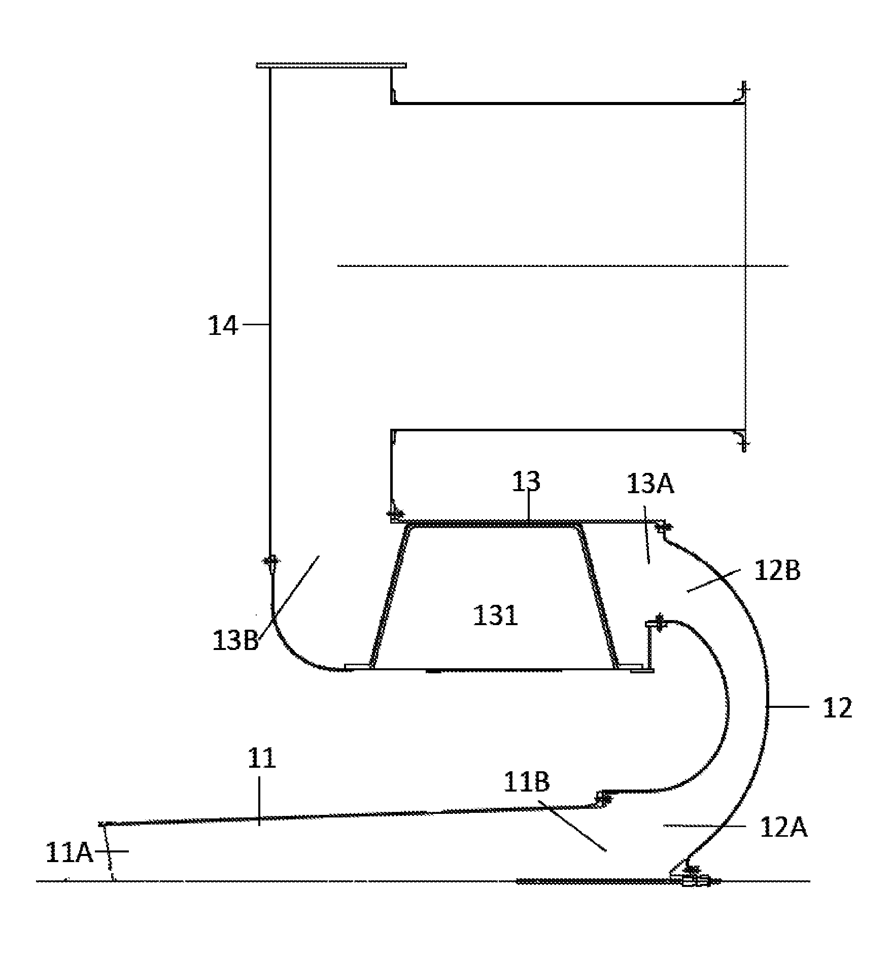
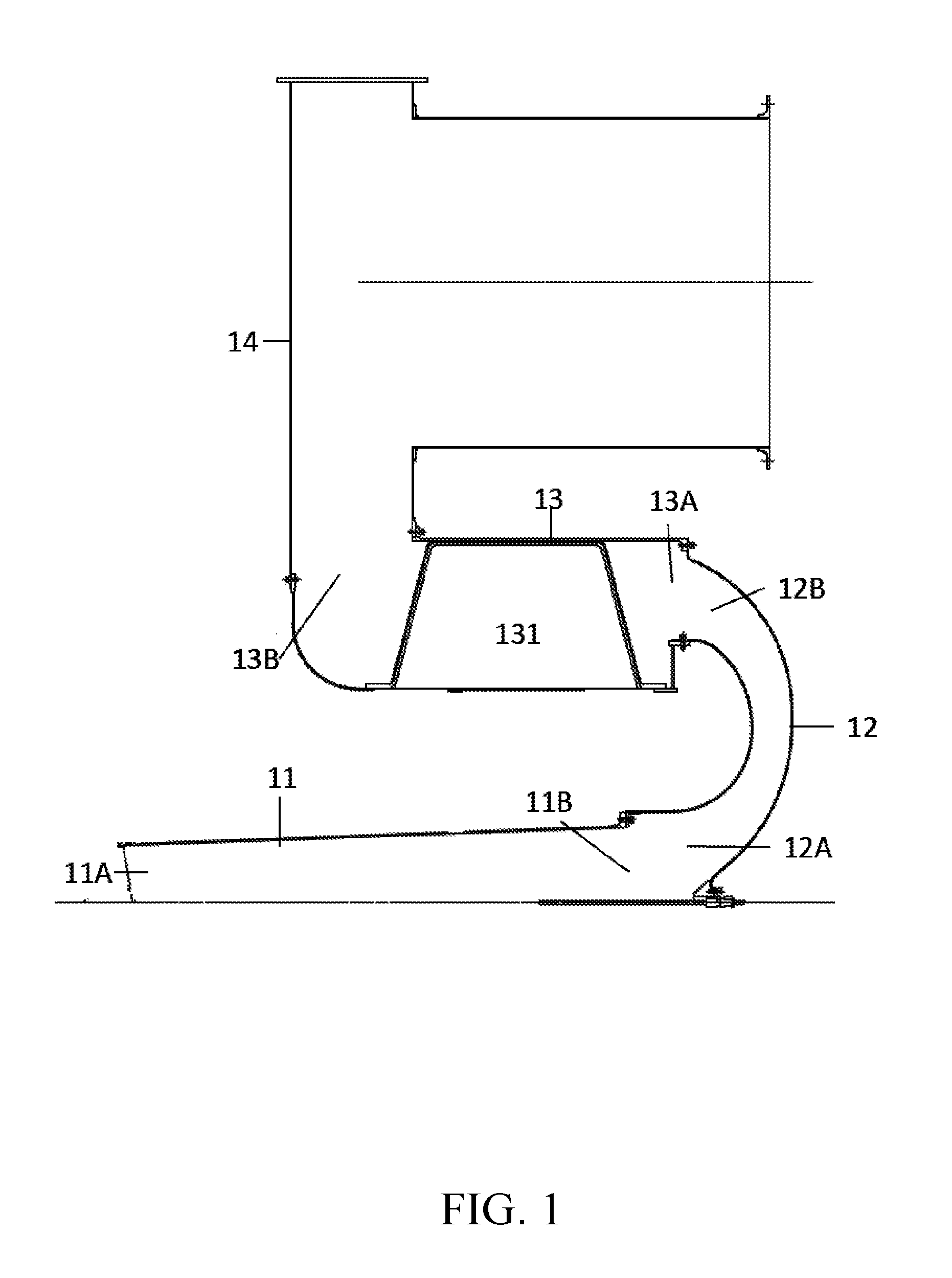
[0012] FIG. 1 is a schematic view of an exhaust channel of a microturbine engine according to an embodiment of the present invention.
DETAILED DESCRIPTION OF THE PREFERRED EMBODIMENTS
[0013] Implementation of the present invention is hereunder illustrated by a specific embodiment. Improved in the art can easily understand other advantages and effects of the present invention by referring to the disclosure contained in the specification.
[0014] Referring to FIG. 1, there is shown a schematic view of an exhaust channel 1 of a microturbine engine according to an embodiment of the present invention. As shown in the diagram, the exhaust channel 1 of a microturbine engine comprises: an expanding segment 11 being a tapering pipe and having an expanding segment outlet 11B and an expanding segment inlet 11A of a smaller diameter than the expanding segment outlet 11B; a bending segment 12 being a U-shaped curved tube and having a bending segment outlet 12B and a bending segment inlet 12A in communication with the expanding segment outlet 11B; a heat exchange segment 13 being a pipe and having a heat exchange segment outlet 13B and a heat exchange segment inlet 13A in communication with the bending segment outlet 12B, wherein the heat exchange segment 13 contains cooling fins 131; and a rear exhaust segment 14 being a pipe or hollow-cored casing, being in communication with the heat exchange segment outlet 13B, and being of a larger internal volume than the heat exchange segment 13.
[0015] To reduce the speed at which a high-temperature gas is discharged from the microturbine engine, the present invention has technical features as follows: the expanding segment is a tapering pipe such that the flow rate of the gas passing the expanding segment is reduced but not to an overly low level, otherwise the heat exchange efficiency of subsequent segments will deteriorate. In a preferred embodiment of the present invention, the expanding segment has a tapering angle no greater than 7.degree..
[0016] To enhance its heat exchange efficiency, a recuperator of an exhaust channel of a microturbine generator must be positioned as close to an exhaust pipe of a microturbine engine as possible to transfer the heat from the high-temperature gas and the heat from the exhaust pipe to the recuperator and thus enhance the heat exchange efficiency. Hence, the engine exhaust pipe and the recuperator segment are parallel, near each other, and in communication with each other by a curved tube. Distribution of streamlines and speed of the gas in the channel depends on the cross-sectional area and angle of the curved tube. In an embodiment of the present invention, the rate of change in cross-sectional area of the bending segment is expressed by 0.1<(.DELTA.A/.DELTA.L)<0.2, where .DELTA.A denotes cross-sectional area of the bending segment, and .DELTA.L denotes length of the bending segment, with a view to preventing an overly large rate of change in cross-sectional area from affecting the streamlines of the gas. The included angle between the bending segment outlet and the heat exchange segment inlet is no greater than 5.degree..
[0017] In an embodiment of the present invention, the rear exhaust segment is of a larger internal volume than the heat exchange segment to prevent generation of exhaust rear pressure and thus reduction in working efficiency of the microturbine engine, and reduce exhaust resistance confronting the outgoing gas, which may even return to cause a reflow in the channel.
[0018] In an embodiment of the present invention, to enhance production efficiency and reduce difficulties in the manufacturing process, the expanding segment, the bending segment, the heat exchange segment and the rear exhaust segment are each made of sheet metal and then welded together to form an exhaust channel of a microturbine engine according to the present invention. Furthermore, owing to rapid development of laminated manufacturing technologies, theoretically speaking, laminated manufacturing (commonly known as 3D printing) can be employed to make an integrally-formed exhaust channel of a microturbine engine, but it has some unsolved drawbacks in terms of processing precision and costs. If its production efficiency and yield is enhanced, it can produce exhaust channels of high structural strength and low weight.
[0019] In conclusion, the present invention provides an exhaust channel of a microturbine engine, characterized by a tapering channel for reducing the speed at which a high-temperature gas is discharged from the microturbine engine and ensuring that the high-temperature gas introduced into the recuperator produces a uniform, low-speed flow field, with a view to preventing any noticeable return region from developing in the channel, minimizing the pressure loss in the channel, and enhancing the heat exchange efficiency of the recuperator.
[0020] In an embodiment of the present invention, the expanding segment, the bending segment, the heat exchange segment and the rear exhaust segment are integrated.
[0021] The embodiments described above are intended only to illustrate the features and advantages of the present invention rather than limit the substantial technical contents of the present invention. Persons skilled in the art can make modifications and variations to the aforesaid embodiments without departing from the spirit and scope of the present invention. Accordingly, the legal protection for the present invention should be defined by the appended claims.
* * * * *
D00000
D00001
XML
uspto.report is an independent third-party trademark research tool that is not affiliated, endorsed, or sponsored by the United States Patent and Trademark Office (USPTO) or any other governmental organization. The information provided by uspto.report is based on publicly available data at the time of writing and is intended for informational purposes only.
While we strive to provide accurate and up-to-date information, we do not guarantee the accuracy, completeness, reliability, or suitability of the information displayed on this site. The use of this site is at your own risk. Any reliance you place on such information is therefore strictly at your own risk.
All official trademark data, including owner information, should be verified by visiting the official USPTO website at www.uspto.gov. This site is not intended to replace professional legal advice and should not be used as a substitute for consulting with a legal professional who is knowledgeable about trademark law.