Blowout Preventer Bonnet Assembly
ALSUP; JOHN L. ; et al.
U.S. patent application number 16/096292 was filed with the patent office on 2019-05-16 for blowout preventer bonnet assembly. This patent application is currently assigned to ELECTRICAL SUBSEA & DRILLING AS. The applicant listed for this patent is ELECTRICAL SUBSEA & DRILLING AS. Invention is credited to JOHN L. ALSUP, MARION E. EAGLES, THOR ARNE HAVERSTAD, J. GILBERT NANCE, ERIK NORBOM, BOLIE C. WILLIAMS.
| Application Number | 20190145217 16/096292 |
| Document ID | / |
| Family ID | 58739318 |
| Filed Date | 2019-05-16 |


View All Diagrams
| United States Patent Application | 20190145217 |
| Kind Code | A1 |
| ALSUP; JOHN L. ; et al. | May 16, 2019 |
BLOWOUT PREVENTER BONNET ASSEMBLY
Abstract
A blow out preventer includes a main body with a main passage arranged therethrough, a ram movable between a first ram position in which the ram is spaced from the main passage and a second ram position in which the ram at least partly interrupts the main passage, and a bonnet releasably secured to the main body. The bonnet includes a hydraulic ram actuator coupled to the ram. The hydraulic ram actuator includes a primary piston arranged within a primary cylinder and fixed to a piston rod, and a secondary piston arranged within a secondary cylinder to be slidable on the piston rod. The primary piston and the secondary piston are each arranged to actuate the ram via the piston rod. The primary piston and the secondary piston each comprise a stroke length, the stroke length of the secondary piston being shorter than the stroke length of the primary piston.
| Inventors: | ALSUP; JOHN L.; (HOUSTON, TX) ; WILLIAMS; BOLIE C.; (HOUSTON, TX) ; NANCE; J. GILBERT; (KATY, TX) ; NORBOM; ERIK; (HOEVIK, NO) ; HAVERSTAD; THOR ARNE; (VENNESLA, NO) ; EAGLES; MARION E.; (HOUSTON, TX) | ||||||||||
| Applicant: |
|
||||||||||
|---|---|---|---|---|---|---|---|---|---|---|---|
| Assignee: | ELECTRICAL SUBSEA & DRILLING
AS STRAUME NO |
||||||||||
| Family ID: | 58739318 | ||||||||||
| Appl. No.: | 16/096292 | ||||||||||
| Filed: | April 24, 2017 | ||||||||||
| PCT Filed: | April 24, 2017 | ||||||||||
| PCT NO: | PCT/NO2017/050100 | ||||||||||
| 371 Date: | October 25, 2018 |
| Current U.S. Class: | 166/339 |
| Current CPC Class: | E21B 33/076 20130101; E21B 33/062 20130101 |
| International Class: | E21B 33/076 20060101 E21B033/076 |
Foreign Application Data
| Date | Code | Application Number |
|---|---|---|
| Apr 27, 2016 | NO | 20160701 |
| Apr 27, 2016 | NO | 20160702 |
| Apr 27, 2016 | NO | 20160705 |
| Apr 27, 2016 | NO | 21160704 |
Claims
1-33. (canceled)
34: A blow out preventer comprising: a main body comprising a main passage arranged therethrough; a ram movable between a first ram position in which the ram is spaced from the main passage and a second ram position in which the ram at least partly interrupts the main passage; and a bonnet releasably secured to the main body, the bonnet comprising a hydraulic ram actuator which is coupled to the ram, the hydraulic ram actuator comprising: a primary piston arranged within a primary cylinder and fixed to a piston rod; and a secondary piston arranged within a secondary cylinder so as to be slidable on the piston rod, wherein, the primary piston and the secondary piston are each arranged to actuate the ram via the piston rod, and the primary piston and the secondary piston each comprise a stroke length, the stroke length of the secondary piston being shorter than the stroke length of the primary piston.
35: The blow out preventer as recited in claim 34, wherein, the piston rod comprises a mechanical stop, and the secondary piston is configured to engage the mechanical stop so as to actuate the ram via the piston rod.
36: The blow out preventer as recited in claim 35, wherein, the secondary cylinder further comprises a recess which is configured to receive the mechanical stop for at least a part of a stroke length of the piston rod.
37: The blow out preventer as recited in claim 34, wherein the primary cylinder is arranged within the bonnet.
38: The blow out preventer as recited in claim 34, wherein the bonnet further comprises: an attachment device; and an actuator unit, wherein, the secondary cylinder is arranged in the actuator unit, and the actuator unit is releasably fixed to the bonnet via the attachment device.
39: The blow out preventer as recited in claim 37, wherein the bonnet further comprises: a first segmented latch ring comprising at least two latch ring parts, each of the at least two latch ring parts comprising a serrated outer profile which is configured to engage a first serrated surface on the bonnet; a first segmented locking ring comprising at least two locking ring parts, each of the at least two locking ring parts being configured to engage with at least one of the at least two latch ring parts; and at least one first fastener, wherein, the attachment device is fixed to the bonnet via the first segmented latch ring and the first segmented locking ring, and the at least one first fastener fixes each of the at least two locking ring parts to either the bonnet or to the actuator unit.
40: The blow out preventer as recited in claim 39, further comprising: a second segmented latch ring comprising at least two latch ring parts, each of the at least two latch ring parts comprising a serrated outer profile which is configured to engage a second serrated surface on the actuator unit; a second segmented locking ring comprising at least two locking ring parts, each of the at least two locking ring parts being configured to engage with at least one of the at least two latch ring parts; a locking device configured to selectively lock the ram in the second ram position; and at least one second fastener, wherein, the locking device is fixed to the actuator unit via the second segmented latch ring and the second segmented locking ring, and the at least one second fastener fixes each of the at least two locking ring parts to either the actuator unit or to the locking device.
41: A blow out preventer comprising: a main body comprising a main passage arranged therethrough; a ram movable between a first ram position in which the ram is spaced from the main passage and a second ram position in which the ram at least partly interrupts the main passage; a bonnet releasably secured to the main body, the bonnet comprising a hydraulic ram actuator which is coupled to the ram; and at least one hydraulic bonnet actuator which is operable independently of the hydraulic ram actuator and which is configured to move the bonnet relative to the main body from at least one of: a bonnet closed position in which the bonnet engages the main body to a bonnet open position in which the bonnet is spaced from the main body, and from the bonnet open position to the bonnet closed position.
42: The blow out preventer as recited in claim 41, wherein, the hydraulic bonnet actuator comprises a first piston extending from the main body to a first cylinder formed within the bonnet and a second piston extending from the main body to a second cylinder formed within the bonnet, the first piston divides the first cylinder into a first operating chamber and a second operating chamber, and the second piston divides the second cylinder into a third operating chamber and a fourth operating chamber.
43: The blow out preventer as recited in claim 42, wherein the hydraulic bonnet actuator further comprises, a first connection channel which fluidly connects the first operating chamber and the third operating chamber, and a second connection channel which fluidly connects the second operating chamber and the fourth operating chamber.
44: The blow out preventer as recited in claim 42, wherein the hydraulic bonnet actuator further comprises, a first hydraulic supply channel which connects a first supply line to the first operating chamber, and a second hydraulic supply channel which connects a second supply line to the fourth operating chamber.
45: The blow out preventer as recited in claim 44, further comprising: a first extendable hydraulic supply line which is arranged to provide hydraulic fluid from the main body to the hydraulic ram actuator in the bonnet open position and in the bonnet closed position.
46: The blow out preventer as recited in claim 45, wherein, the first extendable hydraulic supply line comprises a first tube which extends from the main body into a second passage in the bonnet, the first tube is movable in relation to the second passage and is sealed against the second passage, and the second passage is fluidly connected to the hydraulic ram actuator.
47: The blow out preventer as recited in claim 45, further comprising: a second extendable hydraulic supply line which is arranged to provide hydraulic fluid to the hydraulic ram actuator in the bonnet open position and in the bonnet closed position.
48: The blow out preventer as recited in claim 47, wherein, the second extendable hydraulic supply line comprises a second tube which extends from the main body into a third passage in the bonnet, the second tube is movable in relation to the third passage and is sealed against the third passage, and the third passage is fluidly connected to the hydraulic ram actuator.
49: The blow out preventer as recited in claim 47, further comprising: a bonnet support rail arrangement which is configured to guide the bonnet between the bonnet closed position the bonnet open position, wherein, the first extendable hydraulic supply line is adapted to actuate a ram open movement of the hydraulic ram actuator, and the second extendable hydraulic supply line is adapted to actuate a ram close movement of the hydraulic ram actuator.
50: The blow out preventer as recited in claim 49, wherein the bonnet support rail arrangement comprises: a first support rail comprising a longitudinal axis, the first support rail being fixed to the main body; a first pair of rail support bearings fixed to the bonnet and being spaced apart in the longitudinal axis of the first support rail; a second support rail comprising a longitudinal axis, the second support rail being fixed to the main body; and a second pair of rail support bearings fixed to the bonnet and being spaced apart in the longitudinal axis of the second support rail, wherein, the first pair of rail support bearings are arranged so that an imaginary plane which is generally perpendicular to the longitudinal axis of the first support rail in which a center of gravity of the bonnet lies is located between the first pair of rail support bearings, and the second pair of rail support bearings are arranged so that the imaginary plane is located between the first second of rail support bearings.
51: A blow out preventer comprising: a main body comprising a main passage arranged therethrough; a ram movable between a first ram position in which the ram is spaced from the main passage and a second ram position in which the ram at least partly interrupts the main passage; a bonnet releasably secured to the main body, the bonnet comprising a hydraulic ram actuator which is coupled to the ram; and a first extendable hydraulic supply line, the first extendable hydraulic supply line being arranged to provide hydraulic fluid from the main body to the hydraulic ram actuator in a bonnet open position and in a bonnet closed position.
52: The blow out preventer as recited in claim 51, wherein, the first extendable hydraulic supply line comprises a first tube which extends from the main body into a second passage in the bonnet, the first tube is movable in relation to the second passage and is sealed against the second passage, and the second passage is fluidly connected to the hydraulic ram actuator.
53: The blow out preventer as recited in claim 52, further comprising: a second extendable hydraulic supply line which is arranged to provide hydraulic fluid to the hydraulic ram actuator in the bonnet open position and in the bonnet closed position.
54: The blow out preventer as recited in claim 53, wherein, the second extendable hydraulic supply line comprises a second tube which extends from the main body into a third passage in the bonnet, the second tube is movable in relation to the third passage and is sealed against the third passage, and the third passage is fluidly connected to the hydraulic ram actuator.
55: The blow out preventer as recited in claim 53, wherein, the first extendable hydraulic supply line is adapted to actuate a ram open movement of the hydraulic ram actuator, and the second extendable hydraulic supply line is adapted to actuate a ram close movement of the hydraulic ram actuator.
56: The blow out preventer as recited in claim 51, further comprising: a bonnet support rail arrangement which is configured to guide the bonnet between the bonnet closed position and the bonnet open position.
57: The blow out preventer as recited in claim 54, wherein the bonnet support rail arrangement comprises: a first support rail comprising a longitudinal axis, the first support rail being fixed to the main body; a first pair of rail support bearings fixed to the bonnet and being spaced apart in the longitudinal axis of the first support rail; a second support rail comprising a longitudinal axis, the second support rail being fixed to the main body; and a second pair of rail support bearings fixed to the bonnet and being spaced apart in the longitudinal axis of the second support rail, wherein, the first pair of rail support bearings are arranged so that an imaginary plane which is generally perpendicular to the longitudinal axis of the first support rail in which a center of gravity of the bonnet lies is located between the first pair of rail support bearings, and the second pair of rail support bearings are arranged so that the imaginary plane is located between the first second of rail support bearings.
Description
CROSS REFERENCE TO PRIOR APPLICATIONS
[0001] This application is a U.S. National Phase application under 35 U.S.C. .sctn. 371 of International Application No. PCT/NO2017/050100, filed on Apr. 24, 2017 and which claims benefit to Norwegian Patent Application No. 20160701, filed on Apr. 27, 2016, Norwegian Patent Application No. 20160702, filed on Apr. 27, 2016, Norwegian Patent Application No. 20160704, filed on Apr. 27, 2016, and to Norwegian Patent Application No. 20160705, filed on Apr. 27, 2016. The International Application was published in English on Nov. 2, 2017 as WO 2017/188822 A1 under PCT Article 21(2).
FIELD
[0002] The present invention relates to a bonnet assembly for a blow out preventer and a blow out preventer.
BACKGROUND
[0003] Blowout preventers (BOPs) were developed to cope with extreme erratic pressures and uncontrolled flow emanating from a well reservoir during drilling. Known as a "kick", this flow of pressure can lead to a potentially catastrophic event called a blowout. In addition to controlling the downhole well pressure and the flow of oil and gas, blowout preventers are intended to prevent tubular goods used in well drilling, such as, drill pipe, casing, collars, tools and drilling fluid, from being blown out of the wellbore when a kick or blowout threatens. Blowout preventers are critical to the safety of the crew, the drilling rig, the environment, and to the monitoring and maintenance of well integrity; blowout preventers are thus intended to provide an additional and fail-safe barrier to the systems in which they are included.
[0004] Ram-type blowout preventers are part of an overall pressure control system used in oil and gas operations commonly used as pressure containment and unexpected wellbore pressure spikes and well pressure control events. A ram-type BOP is similar in operation to a gate valve, but uses a pair of opposing steel plungers or, rams. The rams extend toward the center of the wellbore to restrict flow or to retract open to permit flow. The inner and top faces of the rams are fitted with composite steel and elastomeric packers that press against each other, against the wellbore, and around well tubular members running through the wellbore. Outlets at the sides of the BOP housing (body) are used to connect to choke and kill lines or valves. The rams are typically actuated by hydraulic actuators arranged within, or connected to, the BOP housing. The ram type blowout preventer is further integrated with additional well containment and control devices that inclusively make up a subsea blowout preventer stack.
[0005] Previously reported solutions and techniques useful for understanding and practicing the present invention are described in U.S. Pat. Nos. 7,051,990 B2, 2,912,214, 4,969,390 and 8,596,484 B1.
[0006] The operational requirements for blow out preventers can be very demanding and, due to the tendency of the industry to move into harsher and more challenging environments, such as deepwater or arctic areas, these very demanding operational requirements are likely to continue.
SUMMARY
[0007] An aspect of the present invention is to provide improved techniques and solutions in order to provide BOPs having an increased operational reliability, as well as a design which is compact and permits uncomplicated manufacturing and maintenance. Another aspect of the present invention is to provide an improved hydraulically actuated subsea ram type blowout preventer having a ram bonnet with a hydraulically actuated ram actuator.
[0008] In an embodiment, the present invention provides a blow out preventer which includes a main body comprising a main passage arranged therethrough, a ram movable between a first ram position in which the ram is spaced from the main passage and a second ram position in which the ram at least partly interrupts the main passage, and a bonnet releasably secured to the main body. The bonnet comprises a hydraulic ram actuator which is coupled to the ram. The hydraulic ram actuator comprises a primary piston arranged within a primary cylinder and fixed to a piston rod, and a secondary piston arranged within a secondary cylinder so as to be slidable on the piston rod. The primary piston and the secondary piston are each arranged to actuate the ram via the piston rod. The primary piston and the secondary piston each comprise a stroke length, the stroke length of the secondary piston being shorter than the stroke length of the primary piston.
BRIEF DESCRIPTION OF THE DRAWINGS
[0009] The present invention will now be described in greater detail below on the basis of embodiments and of the drawings in which:
[0010] FIG. 1 shows various views of blow out preventers;
[0011] FIG. 2 shows the blow out preventer of FIG. 1 with additional auxiliary tandem actuators arranged between the respective bonnet and the locking devices, and with the hydraulic supply pipes with the bonnet detached and spaced from the main body;
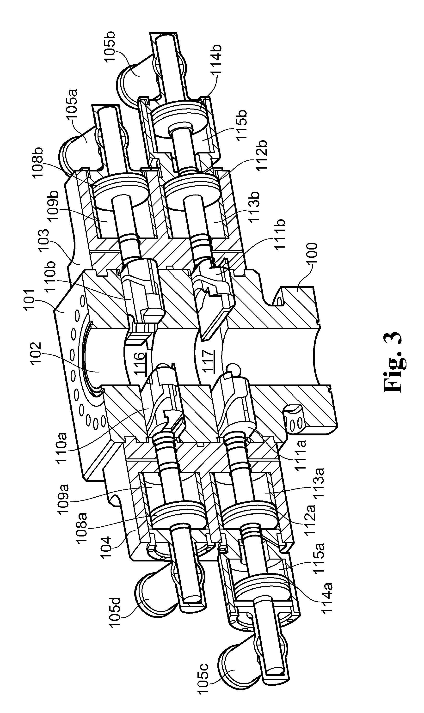
[0012] FIG. 3 shows a view of the blow out preventer of FIG. 2 in an open operational configuration;
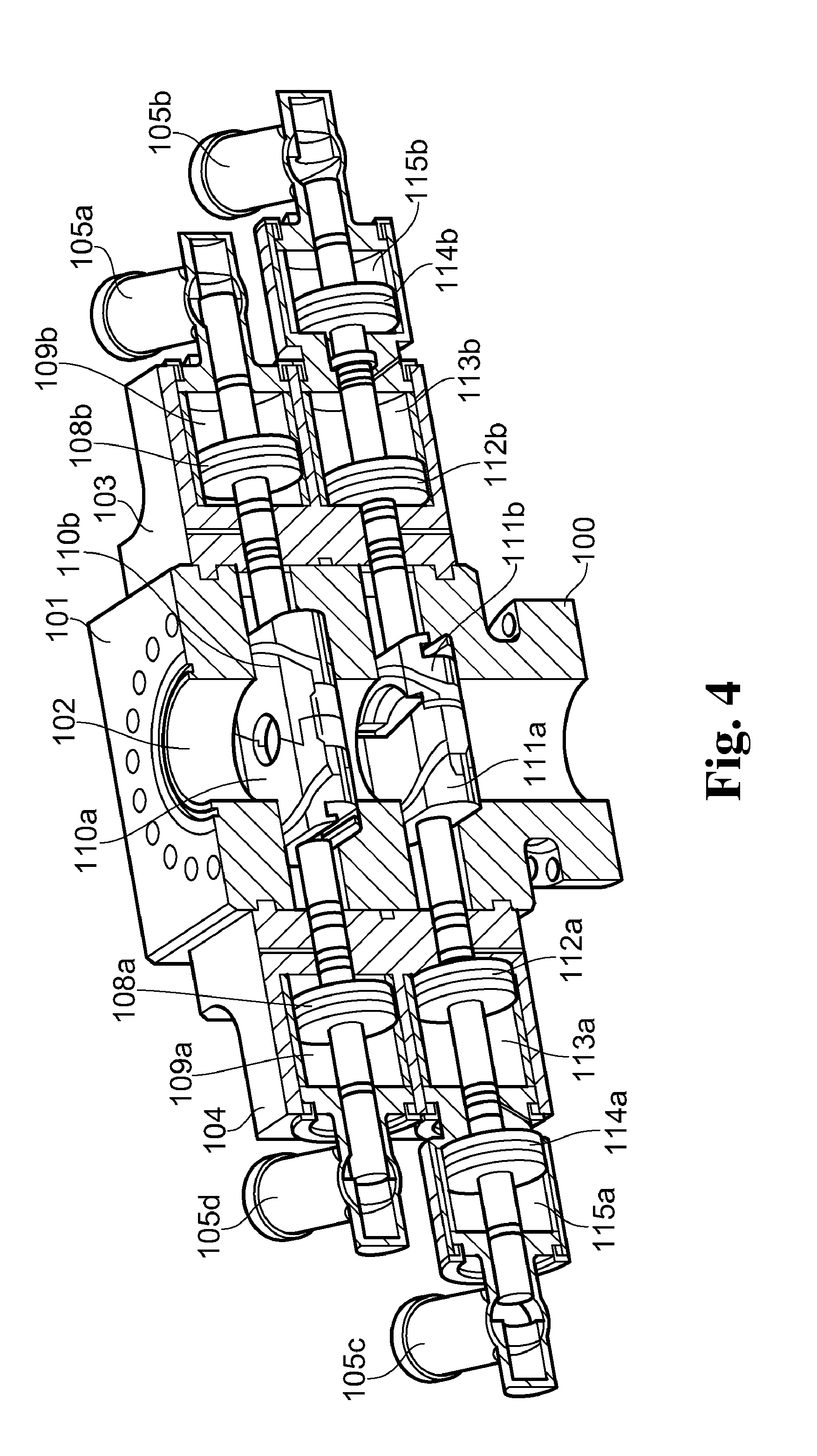
[0013] FIG. 4 shows a top view of the blow out preventer of FIG. 2 in a closed operational configuration, cut centrally between the upper and the lower ram actuator.
[0014] FIG. 5 shows a top view of the blow out preventer of FIG. 2 in a closed operational configuration, cut centrally between the upper and the lower ram actuator;
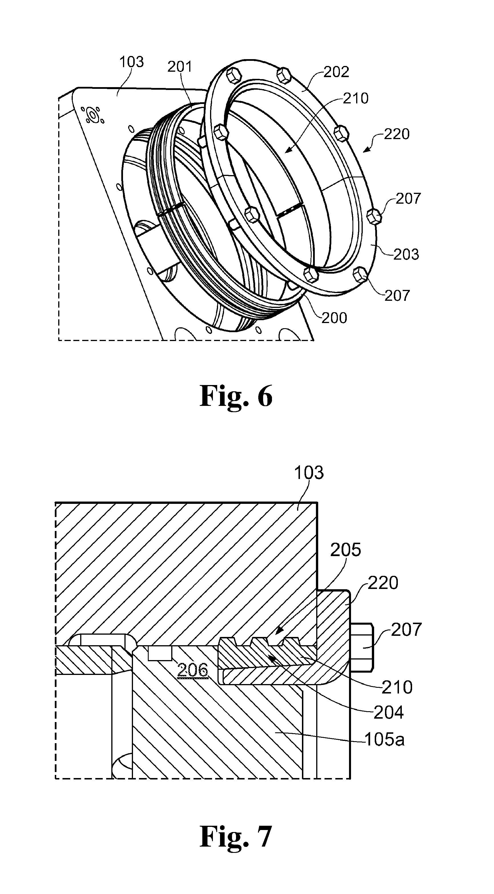
[0015] FIG. 6 shows an attachment device for a blow out preventer in a perspective view;
[0016] FIG. 7 shows an attachment device for a blow out preventer in a cross-sectional view;
[0017] FIG. 8 shows a detailed view of a bonnet assembly and associated components in a perspective view;
[0018] FIG. 9 shows an aspect of a bonnet assembly for a blow out preventer;
[0019] FIG. 10 shows details of the ram actuators and the tandem actuators in the configuration shown in FIGS. 3-5;
[0020] FIG. 11 shows details of the ram actuators and the tandem actuators in the configuration shown in FIGS. 3-5;
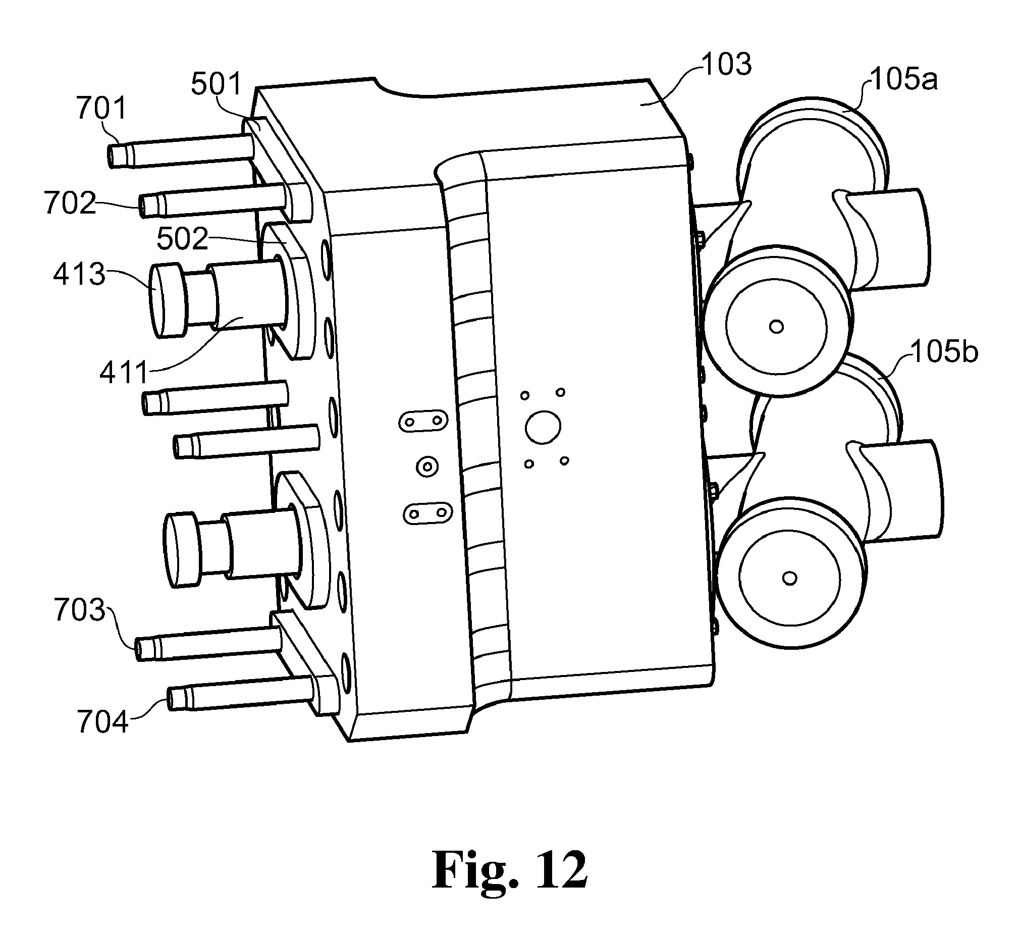
[0021] FIG. 12 shows the bonnet with extendible hydraulic supply pipes for the bonnet in a fully dismantled position where the bonnet has two protrusions;
[0022] FIG. 13 shows the hydraulic supply pipes extending into a respective passage in the bonnet;
[0023] FIG. 14 shows a top view of the blow out preventer of FIG. 2, cut centrally between the upper and the lower ram actuator;
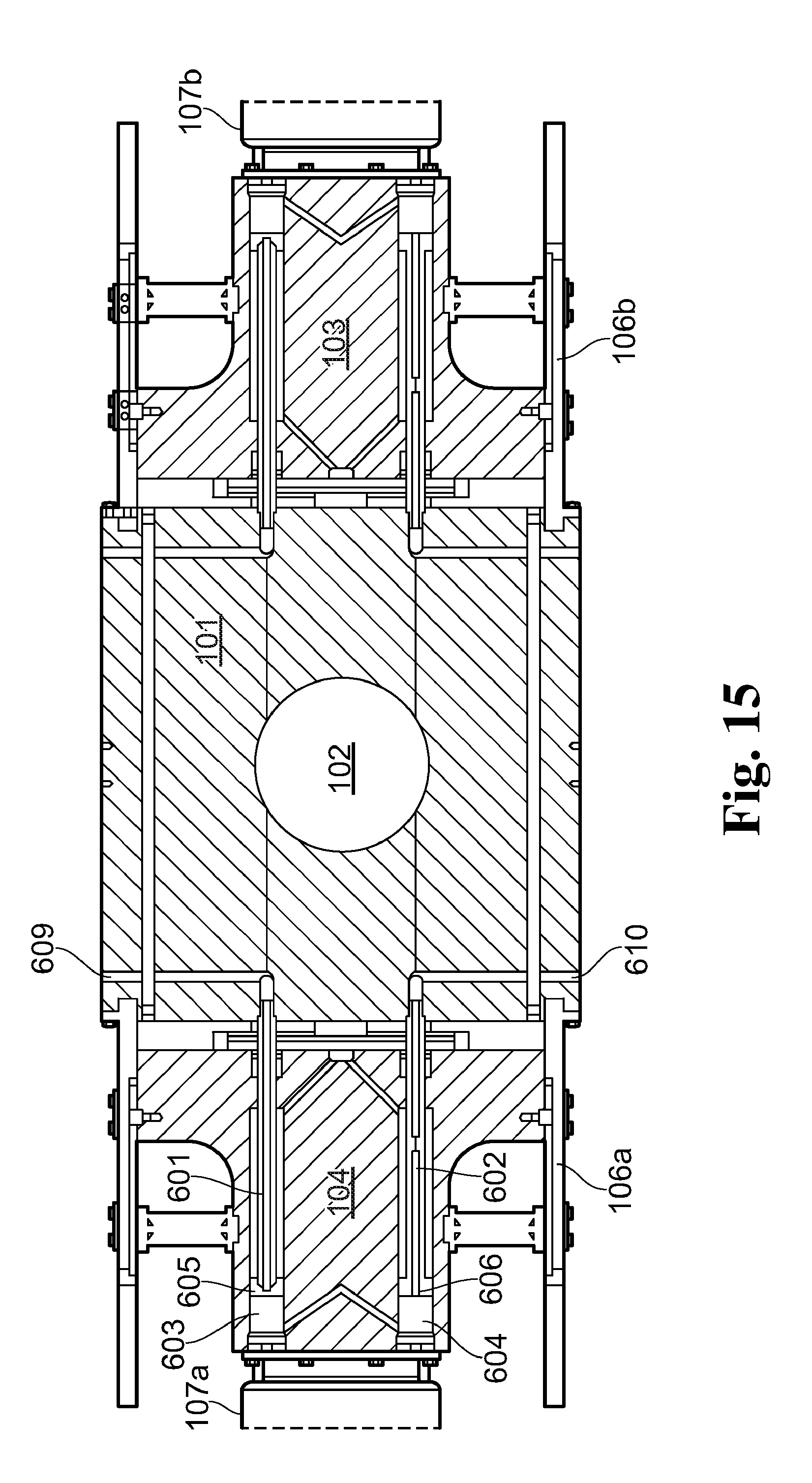
[0024] FIG. 15 shows a top view of the blow out preventer of FIG. 2, cut centrally between the upper and the lower ram actuator;
[0025] FIG. 16 shows various aspects of a hydraulic bonnet actuator for a blow out preventer;
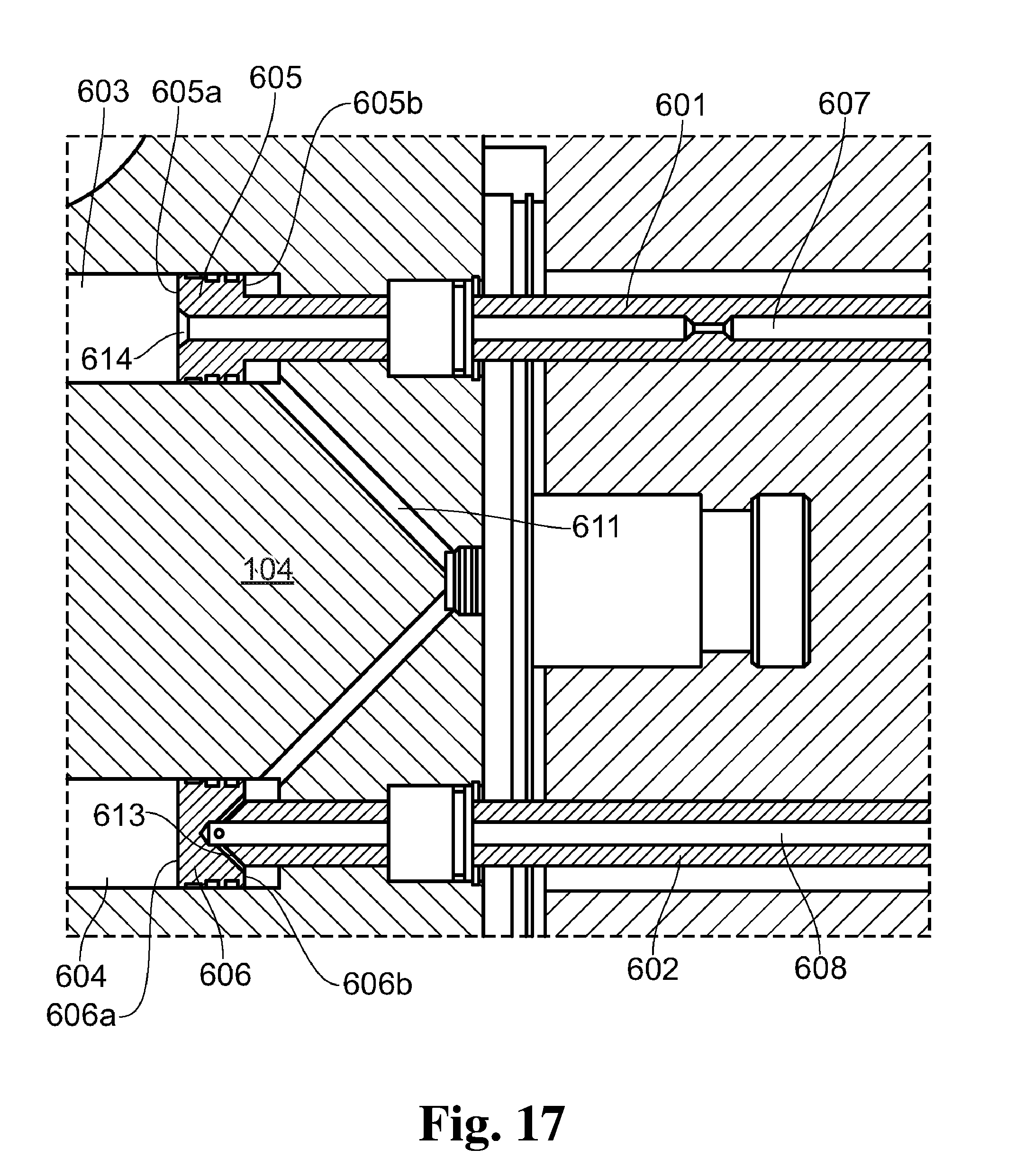
[0026] FIG. 17 shows various aspects of a hydraulic bonnet actuator for a blow out preventer;
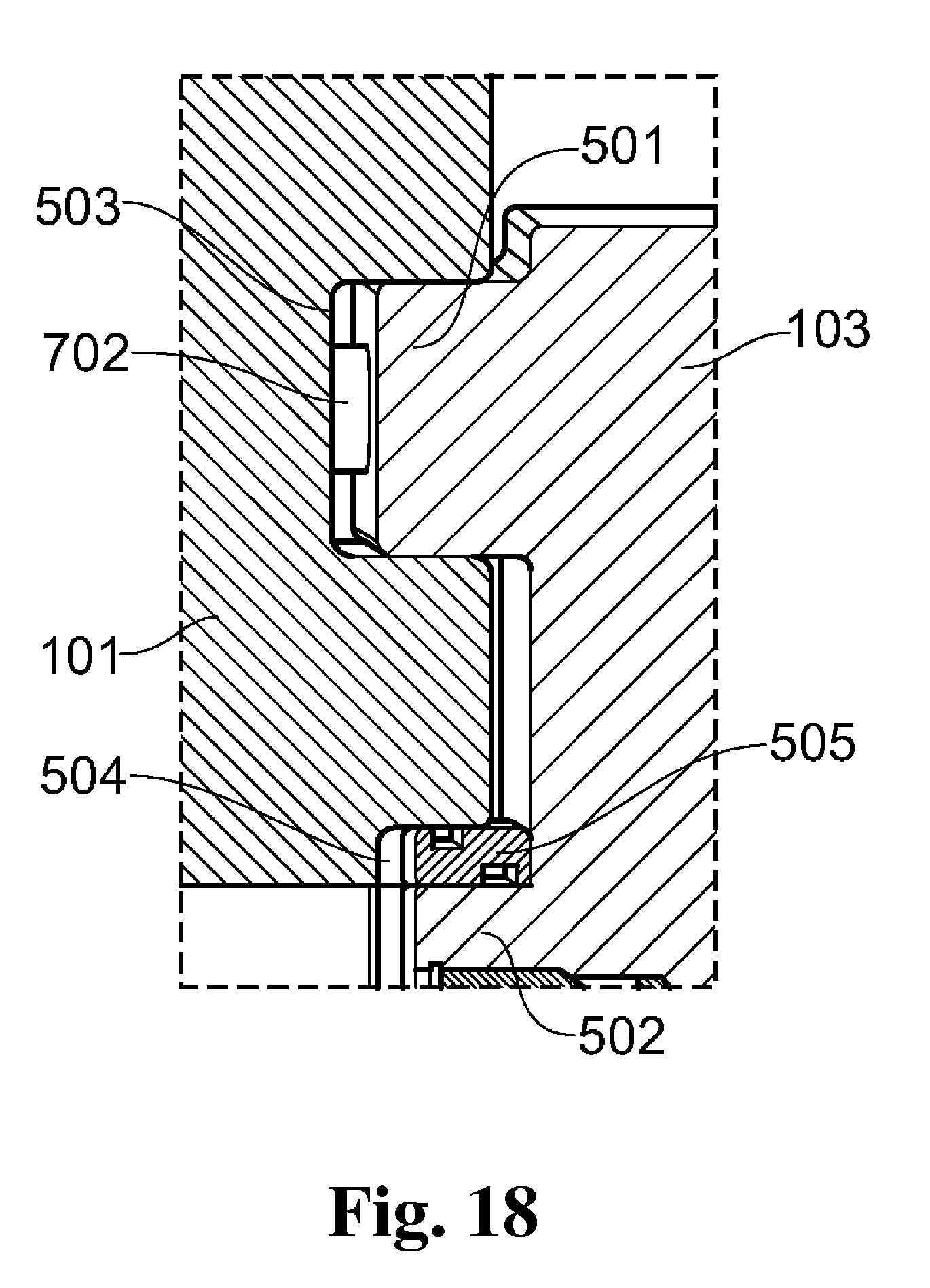
[0027] FIG. 18 shows an aspect of a bonnet assembly for a blow out preventer where the bonnet has two protrusions; and
[0028] FIG. 19 shows an aspect of a bonnet assembly for a blow out preventer where the bonnet has two protrusions.
DETAILED DESCRIPTION
[0029] FIG. 1 shows a blow out preventer having a base 100, a main body 101 with a main passage 102 which will, in use, form part of a wellbore and receive tubulars or other equipment used in the wellbore. Bonnets 103 and 104 are releasably attached to the main body 101, for example, via a set of bolts. The bonnets 103 and 104 comprise ram actuators as will be described in further detail below. Locking devices 105a-d are provided, the locking devices 105a-d being fixed to the bonnets being arranged to lock the ram actuators in an advanced position, as will also be described further below. Support rails 106a and 106b support the weight of the respective bonnet when detached from the main body.
[0030] FIG. 2 shows a blow out preventer having a similar design as that in FIG. 1, with the exception that the blow out preventer in FIG. 2 has additional auxiliary tandem actuators 107a and 107b arranged between the respective bonnet 103, 104 and the locking devices 105b and 105c. The auxiliary tandem actuators 107a and 107b will be described in further detail below.
[0031] In the blow out preventer in FIG. 2, the bonnets 103 and 104 are detached from the main body 101 and supported by the support rails 106a and 106b. This permits the bonnets 103 and 104 to be separated from the main body 101 to allow access to components of the blow out preventer, such as the rams.
[0032] FIGS. 3-5 show various views of the blow out preventer shown in FIG. 2 in an operational configuration. In addition to those components described above, the blow out preventer comprises two sets of rams with associated ram actuators. The ram actuators comprise hydraulically driven piston-cylinder arrangements. An upper pair of rams 110a and 110b are actuated by pistons 108a and 108b, operable in cylinders 109a and 109b, respectively. A lower pair of rams 111a and 111b are actuated by pistons 112a and 112b operable in cylinders 113a and 113b, respectively, and by floating pistons 114a and 114b operating within cylinders 115a and 115b, respectively.
[0033] Each ram 110a, 110b, 111a and 111b is movable in a respective guideway 116 and 117 (see FIG. 3) transverse to the main passage 102. Each ram can thus be moved between a first, open position and a second, closed position. In the embodiment shown, the upper pair of rams 110a and 110b are pipe rams whereas the lower pair of rams 111a and 111b are blind shear rams. Any type or combination of rams may, however, be used in the blow out preventer, including pipe, variable bore pipe, blind, shear, or blind shear rams.
[0034] FIGS. 3 and 5 show the blow out preventer in an open position, whereas FIG. 4 shows the blow out preventer with both set of rams in a closed position. In use, either set of rams will be independently operable, so that the upper pair of rams 110a and 110b can, for example, be operated to close and seal around a pipe or tubular present in the main passage 102. In the case of an emergency, the lower pair of rams 111a and 111b may be operated to shear any object present in the main passage 102 and seal the main passage. This may be done independent of the position of the upper pair of rams 110a and 110b.
[0035] The locking devices 105a-d may be fixed to the bonnets 103 and 104 via an attachment device. The attachment device may also be used to fix the locking devices 105c and 105d to the respective tandem actuators 107a and 107b, and/or to fix the tandem actuators 107a and 107b to the bonnets 103 and 104.
[0036] FIGS. 6 and 7 show an attachment device having a segmented latch ring 210 and a segmented locking ring 220. The latch ring 210 is made up of two latch ring segments 200 and 201, and the locking ring 220 is made up of two lock ring segments 202 and 203. The latch ring 210 and locking ring 220 may be made up of a larger number of segments, for example, 3, 4, 5, or 6 or more segments. The latch ring 210 and locking ring 220 may be made up of a different number of segments, for example, the latch ring 210 may be made up of three or more segments while the locking ring 220 may be made up of two segments.
[0037] The locking device 105a has an annular flange which is inserted into a correspondingly sized circular aperture in the bonnet 103, followed by the latch ring 210 and locking ring 220, so that the annular flange is clamped, and thus held captive, between the bonnet and the latch ring, The segmented latch ring 210 has a series of ridges 204 that engage corresponding ridges 205 on the bonnet or tandem actuator inner diameter to provide an interlocking engagement between male and female profiles. The locking ring 220 engages the latch ring 210 and holds the latch ring 210 in interlocking engagement with the ridges 205. The segmented latch ring 210 contacts a load shoulder 206 on the locking device 105a, or an equivalent load shoulder on the tandem actuator 107a and 107b, to restrain axial movement. Fasteners, which are provided as bolts 207 in the example shown in FIGS. 6 and 7, hold the locking ring 220 in place by securing it to either the bonnet 103, the respective locking device 105a-d, the respective tandem actuator 107a and 107b, or to the latch ring 210.
[0038] Attachment of the tandem actuators 107a and 107b to the bonnet 103, and the locking device 105b to the tandem actuator 107b, can be arranged equivalently. This attachment device thus provides a secure connection between the locking devices 105a-d, the tandem actuators 107a and 107b, and the bonnet 103 and 104, while allowing for a simple and fast removal of the attachment device, for example, for repair or maintenance.
[0039] Reference is now made to FIG. 8, which shows in more detail the bonnet 103 and associated components, and to FIG. 9. The bonnet 103 has a support system comprising support rails 106b and 106c arranged on either side of the bonnet 103 for supporting the weight of the bonnet 103 in the detached position (as shown in FIG. 2). The support rails 106b and 106c each have a longitudinal axis, and an end connector 304 which is fixed to the main body 101. The support system further comprises a support rail bracket 301 and first and second support rail bearings 302 and 303. The first support rail bearing 302 is arranged on the support rail bracket 301, which is fixed to the bonnet 103, while the second support rail bearing 303 is fixed directly to the bonnet 103. The support rail 106b engages with the support rail bearings 302 and 303 to support the support rail 106b whilst allowing the support rail 106b to slide along the support rail bearings 302, 303 parallel to its longitudinal axis. The support rails 106b, 106 may thus be used to control the motion of the bonnet 103.
[0040] The support system comprises a rail stop 305 which cooperates with a slot 306 in the support rail 106b to define an end position of the bonnet, i.e., a bonnet open position. The location of the support rail bearings 302 and 303 (and the equivalent support rail bearings on the opposite side of the bonnet 103) are spaced apart in the longitudinal direction of the support rails 106b and 106c. Their location is arranged to provide that the center of gravity of the bonnet 103 lies on an imaginary plane generally perpendicular to the longitudinal axis of the support rail 106b which falls between the two bearings regardless of the bonnet configuration (with or without tandem actuators), bonnet position (open or closed), ram position (open or closed) or state of assembly (locking devices and actuator piston assemblies installed or uninstalled).
[0041] The blow out preventer may comprise tandem actuators 107a and 107b. The tandem actuators 107a and 107b may be releasably attached to the bonnet 103 via an attachment device, for example, according to that above in relation to FIGS. 6 and 7 or a different type of connection arrangement. Alternatively, the tandem actuators 107a and 107b may be permanently fixed to the bonnet 103.
[0042] By providing the tandem actuators 107a and 107b with a releasable attachment device, the blow out preventer may be adapted for any particular use by the operator. For example, during regular drilling operations, the blow out preventer may be configured as shown in FIG. 3, whereby the tandem actuators 107a and 107b provide additional shearing force for the blind shear rams 111a and 111b to provide that the drill string can be severed effectively. For other types of operations, for example, wireline well intervention, less shearing force may be required and the blow out preventer may be configured as shown in FIG. 1, i.e., without the tandem actuators 107a and 107b. The same flexibility will be achieved if using different types of rams in the blow out preventer, for example, in certain configurations, the blind shear rams 111a and 111b in FIG. 3 may be replaced by an additional set of pipe rams in which case the tandem actuators 107a and 107b may not be necessary.
[0043] FIGS. 10 and 11 show further details of the ram actuators and the tandem actuators in the configuration shown in FIGS. 3-5. The bonnet 103 houses two ram actuators. The ram actuators have cylinders 109b and 113b arranged in the bonnet 103, with respective pistons 108b and 112b. A tandem actuator 107b is provided in conjunction with the lower ram actuator. The tandem actuator 107b also has a cylinder 115b and respective piston 114b. The tandem actuator 107b is secured to the bonnet 103 by an attachment device having a latch ring 210 and a locking ring 220, as described above. Locking devices 105a and 105b are attached in an equivalent manner to the bonnet 103 and the tandem actuator 107b, respectively.
[0044] An upper main rod 411 is fixed to the upper piston 108b and extends out of the bonnet 103. A connector 413 is provided for fixing the upper main rod 411 to a ram, for example pipe ram 110b (see FIG. 5). An upper tail rod 412 is fixed to the upper main rod 411 and/or the upper piston 108b and extends into the locking device 105a. When the upper actuator is in the advanced position, the locking device 105a may be operated to engage the upper tail rod 412 and prevent movement of the upper tail rod 412 away from the main passage 102. The locking device 105a may thus be used to lock the upper actuator in the advanced position.
[0045] A lower main rod 414 is fixed to the lower piston 112b and extends out of the bonnet 103 to a connector 417 for connecting the lower main rod 414 to a ram, for example blind shear ram 111b (see FIG. 5). A connecting rod 415 is fixed to the lower main rod 414 and/or the piston 112b and extends into the tandem actuator 107b. The connecting rod 415 is fixed to a tail rod 416 in the tandem actuator 107b. The tail rod 416 extends into the locking device 105b, and the locking device 105b may be operated to engage the tail rod 416 and to prevent movement of the tail rod 416 away from the main passage 102. The locking device 105b may thus be used to lock the lower actuator in the advanced position.
[0046] The piston 114b of the tandem actuator 107b is a floating piston 114b which is slidably arranged on the tail rod 416. The tail rod 416 comprises a mechanical stop 422. The mechanical stop 422 may be a shoulder on the tail rod 416. When the back side of the floating piston 114b is pressurized in cylinder 115b, the floating piston 114b will be urged towards the mechanical stop 422 and thus contribute to actuating the ram via the tail rod 416, connecting rod 415, and lower main rod 414.
[0047] The floating piston 114b may have a shorter stroke length than the lower piston 112b. This may be beneficial, for example, in the arrangement shown in FIG. 5. When cutting an object in the main passage 102, for example, a drill string, with the blind shear rams 111a and 111b, the highest force requirements will be during the cutting process. After the cut has been done, the final movement of the rams will be to fully close the main passage and actuate the seals. This final movement requires much less actuation force.
[0048] By providing the floating piston 114b with a shorter stroke length than the lower piston 112b, the floating piston 114b may contribute actuation force for part of the ram stroke, while not consuming hydraulic fluid during the rest of the actuation stroke (for example, during the final movement as noted above). This can be achieved by designing the cylinder 115b so that the floating piston 114b is stopped against an end stop within the cylinder after a pre-determined stroke length.
[0049] The cylinder 115b may be provided with a recess 424 being adapted for receiving the mechanical stop 422 during part of the stroke length of the actuator. This allows the end stop for the floating piston 114b to be the end 423 of the cylinder 115b, while the tail rod 416 with the mechanical stop 422 may continue its motion over the final part of the actuation stroke as the floating piston 114b stays in place at the end 423 of the cylinder 115b, the tail rod 416 thus sliding along within the floating piston 114b. This allows the cylinder 115b to be designed with a length substantially equal to the stroke length of the floating piston 114b, thus allowing for a shorter and more compact tandem actuator 107b.
[0050] Hydraulic fluid may be provided to the cylinder 115b of the tandem actuator 107 by means of hydraulic supply pipes 420 and 421 (see FIG. 8) or, alternatively, by hydraulic channels within the body of the tandem actuator 107.
[0051] Various elastomeric seals and bushings, for example, seals 418 and 419, may be provided to seal around the rods 411, 412, 414, 415 and 416, as appropriate. Similarly, the pistons 108b, 112b, and 114b are sealed against their respective cylinders in the conventional manner. The floating piston 114b may, similarly, be sealed against the tail rod 416 as necessary.
[0052] The rods in the shown embodiment are made up of individual segments, i.e., main rod, tail rod and connecting rod, however, they may also be formed in one piece as a single rod.
[0053] The blow out preventer may further comprise extendible hydraulic supply pipes arranged between the main body 101 and the bonnet 103. FIG. 12 shows the bonnet 103 with extendible hydraulic supply pipes 701, 702, 703 and 704 for the bonnet 103 in a fully dismantled position (main body 101 not shown). FIG. 2 shows the hydraulic supply pipes 701 and 702 with the bonnet 103 detached and spaced from the main body 101.
[0054] The ends of hydraulic supply pipe 701 and hydraulic supply pipe 702 are fixed to a hydraulic supply system (not shown) within the main body 101 and extend from the main body 101 into the bonnet 103. FIG. 13 shows the hydraulic supply pipes 701 and 702 extending into a respective passage 705 and 706 in the bonnet 103. The supply pipes 701 and 702 are arranged to be slidable within the respective passage 705 and 706. Seals 707 and 708 are provided in an interface between the passage 705 and 706 and the respective supply pipes 701 and 702.
[0055] The passages 705 and 706 are fluidly connected to the upper ram actuator, specifically the passages 705 and 706 are each connected to the cylinder 109b but on opposite sides of the piston 108b. Providing hydraulic fluid to pipe 701 thereby produces an opening motion of the upper ram actuator, while providing hydraulic fluid to pipe 702 produces a closing motion of the upper ram actuator.
[0056] The supply pipes 703 and 704 are arranged equivalently, and connected to the lower ram actuator, i.e., fluidly connected to cylinder 113b. Bonnet 104 is arranged with extendible hydraulic supply pipes equivalently.
[0057] The extendible hydraulic supply pipes thus maintain fluid communication between the hydraulic supply system in the main body 101 and the ram actuators at any time, also when the bonnets 103 and 104 are in the detached position and spaced from the main body 101. This allows operation of the ram actuators by the BOP's main hydraulic system regardless of the position of the bonnet 103 or 104, for example, for moving the rams during maintenance, testing or replacement when the bonnet is in the position shown in FIG. 2.
[0058] Referring now to FIGS. 14-17, the blow out preventer may further comprise a hydraulic bonnet actuator which is operable to move the bonnet 103 or 104 relative to the main body 101. FIGS. 14 and 15 show a top view of the blow out preventer shown in FIG. 2, cut centrally between the upper and the lower ram actuator (see also FIG. 5).
[0059] A first piston rod 601 and a second piston rod 602 are provided, the first and second piston rods being fixed to the main body 101. The first and second piston rods 601 and 602 extend into a respective first cylinder 603 and a second cylinder 604 in the bonnet 104. Piston heads 605 and 606 are provided on the ends of piston rods 601 and 602 and are operable within cylinders 603 and 604 so as to create a piston front side 605a and 606a (see FIG. 17) and a piston back side 605b and 606b for each of the piston heads 605 and 606. By pressurizing the respective chamber or chambers within cylinders 603 and/or 604, the hydraulic bonnet actuator may move the bonnet 104 relative to the main body 101.
[0060] Piston rods 601 and 602 may comprise respective fluid channels 607 and 608 (see FIG. 17) therethrough, whereby hydraulic fluid may be transmitted from a hydraulic fluid supply 609 and 610 in the main body 101 to the cylinders 603 and 604. Fluid channel 607 in piston rod 601 ends in the fluid chamber delimited by piston front side 605a, i.e. the fluid chamber in front of the piston head 605 within cylinder 603. An opening 614 extending through piston head 605 is provided for this purpose. Fluid channel 608 ends in the fluid chamber delimited by piston back side 606b, i.e., the fluid chamber behind piston head 606 within cylinder 604. A fluid channel 613 is provided in the piston head 606 for this purpose.
[0061] Communication channel 612 (see FIG. 16) provides fluid communication between cylinders 603 and 604 substantially at their outermost ends. Communication channel 611 provides fluid communication between cylinders 603 and 604 substantially at their innermost ends. Since the cylinders 603 and 604 are each divided into two fluid chambers by the pistons 605 and 606, it can be seen that the communication channels 611 and 612 will equalize the pressures acting on the front side of the pistons 605 and 606, and equalize the pressures acting on the back side of pistons 605 and 606. Providing fluid pressure through channel 607 will therefore provide an actuation force from both cylinder/piston arrangements, and produce a force driving the bonnet 104 away from the main body 101. Conversely, providing a fluid pressure through channel 608 will produce a force driving the bonnet 104 towards the main body 101.
[0062] Bonnet 103 may be arranged equivalently thereto.
[0063] It is therefore possible to displace the bonnets 103 and 104 from the main body 101 via the hydraulic bonnet actuator without the need for external force or support, as well as bring the bonnets 103 and 104 back towards the main body 101 for re-attachment. The bonnets 103 and 104 can be moved relative to the main body 101 independently of the ram actuators or their positions. This can be advantageous, for example, for testing of the ram actuator functionality, whereby the bonnet actuator will maintain the bonnet in a given position while the ram actuator(s) is/are being operated for testing or other purposes.
[0064] The blow out preventer may further comprise an end capture providing an interlocking engagement between male and female profiles to reduce stresses and deflections in the main body 101 and/or the bonnets 103 and 104.
[0065] FIGS. 12, 18 and 19 show the bonnet 103 having a protrusion 501 and a protrusion 502. The protrusion 501 is adapted for interlocking arrangement with a corresponding recess 503 in the main body 101 and the protrusion 502 similarly cooperates with a recess 504 (see FIGS. 18 and 2.)
[0066] The main rod 411 may extend out of the bonnet 103 through the protrusion 502 (see FIG. 12). This may provide the advantage that the interlocking engagement of the protrusion 502 and the recess 504 is provided in a region of the bonnet 103 and main body 101 where tension stresses are high during operation. A support element 505 (see FIG. 18) may, optionally, be provided to further improve stress distribution in this region.
[0067] Hydraulic supply pipes 701 and 702 may extend through the protrusion 501.
[0068] According to various embodiments of the present invention, there is thus provided a new and improved subsea ram type blow out preventer. The blow out preventer according to the present invention may provide advantages of design simplicity, ease of manufacturing and maintenance, improved reliability of hydraulic functions and system reliability.
[0069] The present invention is not limited to embodiments described herein; reference should be had to the appended claims.
* * * * *
D00000
D00001
D00002
D00003
D00004
D00005
D00006
D00007
D00008
D00009
D00010
D00011
D00012

D00013
D00014

D00015
D00016
D00017

XML
uspto.report is an independent third-party trademark research tool that is not affiliated, endorsed, or sponsored by the United States Patent and Trademark Office (USPTO) or any other governmental organization. The information provided by uspto.report is based on publicly available data at the time of writing and is intended for informational purposes only.
While we strive to provide accurate and up-to-date information, we do not guarantee the accuracy, completeness, reliability, or suitability of the information displayed on this site. The use of this site is at your own risk. Any reliance you place on such information is therefore strictly at your own risk.
All official trademark data, including owner information, should be verified by visiting the official USPTO website at www.uspto.gov. This site is not intended to replace professional legal advice and should not be used as a substitute for consulting with a legal professional who is knowledgeable about trademark law.