Eccentric Shaft For A Compaction Machine
Persson; Andreas ; et al.
U.S. patent application number 16/097064 was filed with the patent office on 2019-05-16 for eccentric shaft for a compaction machine. This patent application is currently assigned to Dynapac Compaction Equiment AB. The applicant listed for this patent is Dynapac Compaction Equiment AB. Invention is credited to Hans Christensen, Andreas Persson.
| Application Number | 20190145060 16/097064 |
| Document ID | / |
| Family ID | 60160883 |
| Filed Date | 2019-05-16 |

| United States Patent Application | 20190145060 |
| Kind Code | A1 |
| Persson; Andreas ; et al. | May 16, 2019 |
ECCENTRIC SHAFT FOR A COMPACTION MACHINE
Abstract
An eccentric shaft (1) for a compaction machine comprising at least one pair of straight circular cylindrical bearing seats (2,3) arranged on either side of a center of gravity (TP) of the eccentric shaft (1). The bearing seats (2,3) are arranged such that cylinder axes (4, 5) thereof approximately intersect or cross each other at a concave angle (V), less than 179.8 degrees, towards the center of gravity (TP) when the eccentric shaft (1) is at rest.
| Inventors: | Persson; Andreas; (Karlskrona, SE) ; Christensen; Hans; (Karlskrona, SE) | ||||||||||
| Applicant: |
|
||||||||||
|---|---|---|---|---|---|---|---|---|---|---|---|
| Assignee: | Dynapac Compaction Equiment
AB Karlskrona SE |
||||||||||
| Family ID: | 60160883 | ||||||||||
| Appl. No.: | 16/097064 | ||||||||||
| Filed: | April 26, 2017 | ||||||||||
| PCT Filed: | April 26, 2017 | ||||||||||
| PCT NO: | PCT/SE2017/050408 | ||||||||||
| 371 Date: | October 26, 2018 |
| Current U.S. Class: | 404/117 |
| Current CPC Class: | F16C 2350/00 20130101; F16C 3/18 20130101; E01C 19/286 20130101 |
| International Class: | E01C 19/28 20060101 E01C019/28; F16C 3/18 20060101 F16C003/18 |
Foreign Application Data
| Date | Code | Application Number |
|---|---|---|
| Apr 29, 2016 | SE | 1600149-7 |
Claims
1. An eccentric shaft for a compaction machine, the eccentric shaft comprising: at least one pair of straight circular cylindrical bearing seats arranged on either side of a center of gravity (TP) of the eccentric shaft, the bearing seats defining multiple cylinder axes, wherein the bearing seats are arranged such that the multiple cylinder axes approximately intersect or cross each other at a concave angle (V) towards the center of gravity (TP) when the eccentric shaft is at rest, the angle (V) being less than 179.8 degrees.
2. The eccentric shaft according to claim 1, wherein the multiple cylinder axes approximately intersect and the center of gravity (TP) lies approximately in a plane determined by the intersecting cylinder axes.
3. The eccentric shaft according to claim 1, wherein the multiple cylinder axes cross each other and the center of gravity (TP) lies approximately in a plane determined by a first one of the multiple cylinder axes and an intersecting line in parallel with a second one of the multiple cylinder axes.
4. The eccentric shaft according to claim 1, wherein the angle (V) is greater than 178 degrees.
5. The eccentric shaft according to claim 1, wherein the angle (V) is greater than 179 degrees.
6. The eccentric shaft according to claim 1, wherein the bearing seats define two cylinder axes each associated with a respective one of the bearing seats.
Description
TECHNICAL FIELD
[0001] The invention relates to the design of eccentric shafts for compaction machines, such as road rollers and vibrator plates. The eccentric shafts are rotatably connected via bearings to rollers/bottom plates of the road rollers/vibrator plates and are intended to cause them to vibrate when the shafts are caused to rotate at an appropriate operating speed. The eccentric shafts assume a slightly curved shape during the rotational operation due to the effect of centrifugal force on the eccentrically displaced center of gravity on of the shaft. The bent shape causes an unwanted inclination of bearing seats of the eccentric shaft.
PRIOR ART
[0002] In the American patent U.S. Pat. No. 8,206,061 an eccentric shaft is disclosed which is optimized with respect to (low) moment of inertia. The shaft comprises an I-shaped section to counteract the tendency of the shaft to bend during rotational operation. In the Swedish patent SE 53 704, a tendency of an easy-to-start eccentric shaft to bend is limited by a calculated consideration of bending stress in a most heavily loaded portion of the shaft. Thus, inclination of bearings of the eccentric shaft becomes manageable, but it would be advantageous if the inclination could be minimized or eliminated completely. Bending of the known eccentric shaft and inclination of bearing seats thereof are illustrated in FIGS. 1-2 of the present application.
OBJECT OF THE INVENTION
[0003] The object of the present invention is to obtain an eccentric shaft where inclination at the bearings is almost eliminated when the shaft is rotating during operation.
BRIEF SUMMARY OF THE INVENTION
[0004] The present invention achieves this object in that the eccentric shaft is provided with a calculated shape change which results in that bearing seats of the shaft are straightened when the shaft is rotating during operation. In a compaction machine this is rendered possible by means of an eccentric shaft comprising at least one pair of straight circular cylindrical bearing seats arranged on either side of a center of gravity of the eccentric shaft, wherein the bearing seats are arranged such that cylinder axes thereof approximately intersect or cross each other at a concave angle, less than 179.8 degrees, towards the center of gravity when the eccentric shaft is at rest.
[0005] Preferably, the cylinder axes of the bearing seats approximately intersect, wherein the center of gravity lies approximately in a plane determined by the intersecting cylinder axes.
[0006] Alternatively, the cylinder axes of the bearing seats cross each other, wherein center of gravity lies approximately in a plane determined by one of the cylinder axes and an intersecting line in parallel with the other of the cylinder axes.
[0007] Preferably, the angle is greater than 178 degrees, and more preferably greater than 179 degrees.
[0008] In summary, the present invention provides embodiments where inclination at the bearings is almost eliminated. The invention is particularly suitable for slender eccentric shafts which are designed to provide a low moment of inertia in order to be easy to start.
BRIEF DESCRIPTION OF THE DRAWINGS
[0009] The invention will be described in detail with reference to the accompanying FIGS. 1-4.
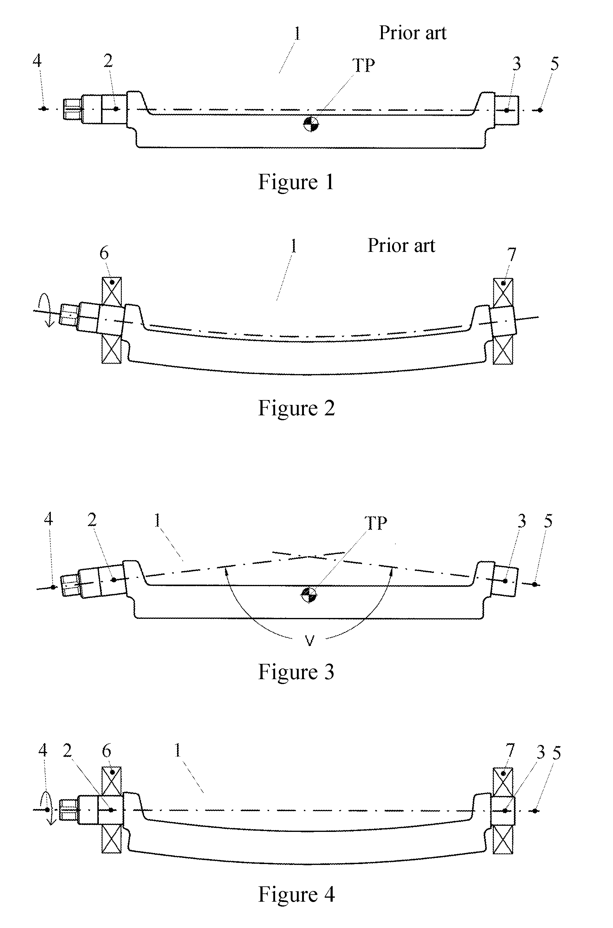
[0010] FIG. 1 shows a previously known eccentric shaft when it is at rest.
[0011] FIG. 2 shows the known eccentric shaft of FIG. 1 when rotating during operation.
[0012] FIG. 3 shows an eccentric shaft made according to the present invention, in a view across its longitudinal dimension and when the shaft is at rest.
[0013] FIG. 4 shows the eccentric shaft of FIG. 3 when rotating during operation.
DETAILED DESCRIPTION OF PREFERRED EMBODIMENTS
[0014] FIG. 1 shows a prior art eccentric shaft 1, comprising a pair of circular cylindrical bearing seats 2, 3 arranged on either side of a center of gravity TP of the eccentric shaft 1. The position description "either side" refers in this context to positions along the longitudinal dimension of the eccentric shaft 1. The bearing seats 2, 3 define cylinder axes 4 and 5, respectively, which axes approximately coincide according to theoretical intentions. However, in series production of eccentric shafts 1, the cylinder axes 4, 5 will randomly coincide, cross each other and intersect as a result of normal deviations. The center of gravity TP is somewhat radially offset from the coinciding cylinder axes 4, 5 to give the eccentric shaft 1 an eccentric action when it is rotating.
[0015] FIG. 2 shows how the known eccentric shaft 1 of FIG. 1 bends when the shaft 1 is rotating. The eccentric shaft 1 is connected via a shaft coupling to a drive motor (not shown) which drivingly rotates the eccentric shaft 1. The bending is extremely exaggerated in the figure to illustrate the phenomenon. Bearings 6, 7 are adapted to cater for the axial displacement that occurs when the eccentric shaft 1 bends. The bent shape also causes an undesired inclination at the bearings 6, 7 of the eccentric shaft 1. It is fully possible to arrange the bearings 6, 7 so that they can handle inclination, but often inclination causes increased thermal stress and shortened length of service of bearings 6, 7.
[0016] FIG. 3 shows a first embodiment of an eccentric shaft 1 according to the present invention. The eccentric shaft 1 has the same performance and is driven and journalled in the same way as the eccentric shaft 1 in FIG. 1-2. The eccentric shaft 1 comprises a pair of circular cylindrical bearing seats 2, 3 arranged on either side of the center of gravity TP of the eccentric shaft 1. The bearing seats 2, 3 define cylinder axes 4 and 5, respectively. The bearing seats 2, 3 are arranged such that their cylinder axes 4, 5 approximately intersect and in such a way that the center of gravity TP lies approximately in a plane determined by the intersecting cylinder axes 4, 5. The bearing seats 2, 3 are also arranged in such a manner that their cylinder axes 4, 5 intersect at a somewhat concave angle V towards the center of gravity TP. The concavity is strongly exaggerated in the figure.
[0017] As mentioned earlier in connection with FIG. 1, normal deviations in series production and randomness can cause a concave angle V. However, such eccentric shafts do not provide any noticeable or significant technical effect, such as the effect aimed at in the present application. It is unlikely that even the most wide-ranging production tolerance would lead to concave angles V less than 179.8 degrees. Claim 1 of the present application does therefore exclude eccentric shafts which exhibit concave angles of 179.8 degrees or greater.
[0018] The angle V is 179.4 degrees and is determined by a theoretical calculation of an angular change at the bearing seats 2, 3 when the eccentric shaft 1 is rotating. The bearing seats 2, 3 are in this case calculated to tilt 0.3 degrees during rotational operation and the angle V is therefore determined to be 180-0.3-0.3=179.4 degrees. Accordingly, the start of the eccentric shaft 1 will occur while the bearing seats 2, 3 incline 0.3 degrees each. The previously mentioned shaft coupling will therefore be imposed a small wobbling motion during start of the eccentric shaft 1. However, it is of course possible to find shaft couplings capable of starting with angles V down to 179 degrees or to use other types of coupling arrangements that can handle starts with angles down to 178 degrees. The term "approximately", as used above, refers in this context to deviations normally found as a result of more or less wide-ranging production tolerances. In the above-described first embodiment, it is assumed that the eccentric shaft 1 is produced to the strictest possible tolerances. This provides the best prerequisites for achieving the advantages of the invention. For wider production tolerances, or for other reasons, it appears better to describe the cylinder axes 4, 5 as crossing each other. Even such a second embodiment of the invention provides good conditions for achieving the advantages of the invention. The angle V and the above-mentioned plane are in that case determined by the angle between one of the cylinder axes 4, 5 and an intersecting line in parallel with the other of the cylinder axes 4, 5. The eccentric shaft 1 is most conveniently made of cast iron or cast steel and its bearing seats 2, 3 and arrangements for coupling connections, are machined by a multi-operation machine or the like. It is also possible, but not recommended, to bend the eccentric shaft 1 to arrive at the angle V. It is also possible to shape the central portion of the eccentric shaft slightly bent (instead of straight) to thus provide for and guarantee the desired shape change during rotational operation.
[0019] FIG. 4 shows how the calculated shape change during rotational operation of the eccentric shaft 1 results in bending of the shaft 1 and the expected straightening of its bearing seats 2, 3. Rotational operation thus results in an addition of 0.3+0.3 degrees to the 179.4 degrees depicted in FIG. 3. The alignment of the bearing seats 2, 3 and the corresponding cylinder axes 4, 5 causes the axes 4, 5 to approximately coincide with a rotational center axis around which the rotational operation takes place. The bearings 6, 7 will thus be loaded under ideal conditions since inclination of the bearing seats 2, 3 is almost eliminated when the eccentric shaft 1 is rotating.
[0020] When interpreting the claims of the present application, it is important to note that known eccentric shafts that exhibit the above-described concave angles due to unintentional deformation due to transport damage, breakdown or the like are to be disregarded.
* * * * *
D00000
D00001
XML
uspto.report is an independent third-party trademark research tool that is not affiliated, endorsed, or sponsored by the United States Patent and Trademark Office (USPTO) or any other governmental organization. The information provided by uspto.report is based on publicly available data at the time of writing and is intended for informational purposes only.
While we strive to provide accurate and up-to-date information, we do not guarantee the accuracy, completeness, reliability, or suitability of the information displayed on this site. The use of this site is at your own risk. Any reliance you place on such information is therefore strictly at your own risk.
All official trademark data, including owner information, should be verified by visiting the official USPTO website at www.uspto.gov. This site is not intended to replace professional legal advice and should not be used as a substitute for consulting with a legal professional who is knowledgeable about trademark law.