Method For Manufacturing Fine Free Carbon Dispersion Type Cemented Carbide, Cutting Tip With Exchangeable Cutting Edge, Machined
DOI; Yoshihiko
U.S. patent application number 16/309694 was filed with the patent office on 2019-05-16 for method for manufacturing fine free carbon dispersion type cemented carbide, cutting tip with exchangeable cutting edge, machined. The applicant listed for this patent is UGEL CORPORATION. Invention is credited to Yoshihiko DOI.
| Application Number | 20190144973 16/309694 |
| Document ID | / |
| Family ID | 62491900 |
| Filed Date | 2019-05-16 |
| United States Patent Application | 20190144973 |
| Kind Code | A1 |
| DOI; Yoshihiko | May 16, 2019 |
METHOD FOR MANUFACTURING FINE FREE CARBON DISPERSION TYPE CEMENTED CARBIDE, CUTTING TIP WITH EXCHANGEABLE CUTTING EDGE, MACHINED PRODUCT FORMED FROM ALLOY, AND METHOD FOR MANUFACTURING SAME
Abstract
The present invention relates to a cemented carbide and coated cemented carbide which contain free carbons, and provides a cemented carbide which enables to remove or reduce the disadvantages of the free carbons even if the cemented carbide contains the free carbons, specifically to decrease in the strength is reduced by finely dispersing the free carbons even if the cemented carbide contains the free carbons and to obtain a beautiful mirror surface on a mirror-finished surface by finely dispersing free carbons in the cemented carbide. The present invention is a cemented carbide composed of tungsten carbide (WC) and cobalt (Co), which contains carbon in such an amount range that no solid carbon is contained in a liquid phase while the liquid phase is present at a high temperature, characterized in that the maximum diameter of the pores resulting from the free carbons is 20 .mu.m or smaller.
| Inventors: | DOI; Yoshihiko; (Osaka-shi, Osaka, JP) | ||||||||||
| Applicant: |
|
||||||||||
|---|---|---|---|---|---|---|---|---|---|---|---|
| Family ID: | 62491900 | ||||||||||
| Appl. No.: | 16/309694 | ||||||||||
| Filed: | December 7, 2017 | ||||||||||
| PCT Filed: | December 7, 2017 | ||||||||||
| PCT NO: | PCT/JP2017/044080 | ||||||||||
| 371 Date: | December 13, 2018 |
| Current U.S. Class: | 428/546 |
| Current CPC Class: | B22F 1/0007 20130101; C22C 1/051 20130101; C22C 1/05 20130101; B22F 3/1035 20130101; B22F 2998/10 20130101; C22C 29/04 20130101; C22C 29/08 20130101; B22F 2998/10 20130101; C22C 29/08 20130101; B22F 1/007 20130101; B22F 3/02 20130101; B22F 3/1035 20130101 |
| International Class: | C22C 1/05 20060101 C22C001/05; C22C 29/08 20060101 C22C029/08 |
Foreign Application Data
| Date | Code | Application Number |
|---|---|---|
| Dec 9, 2016 | JP | 2016-239026 |
| Aug 9, 2017 | JP | 2017-153862 |
Claims
1-7. (canceled)
8. A method for manufacturing a cemented carbide composed of tungsten carbide (WC) and cobalt (Co), wherein: the cemented carbide contains 0.02 mass % or more to 0.15 mass % or less of free carbons; free carbons are finely dispersed in the cemented carbide; shrinkage during sintering occurs evenly; the cemented carbide in which a maximum diameter of pores resulting from the free carbons is 20 .mu.m or smaller is defined as Cemented carbide A; the cemented carbide in which a maximum diameter of pores resulting from the free carbons is 15 .mu.m or smaller is defined as Cemented carbide B; the cemented carbide in which a maximum diameter of pores resulting from the free carbons is 10 .mu.m or smaller is defined as Cemented carbide C; the Cemented carbide A, B or C to which chromium carbide or chromium nitride is added in an amount of 2 to 18 mass % based on cobalt (Co) content is defined as Cemented carbide D; the Cemented carbide A, B, C or D in which a part of tungsten carbide (WC) is replaced by any one or combinations of: a carbide, a nitride or a carbonitride of transition metal of groups 4 and 5 in the periodic table; and a double carbide or a double carbonitride of tungsten (W) with the carbide, the nitride or the carbonitride of the transition metal is defined as Cemented carbide E; and the Cemented carbide E in which a .beta.-free layer is formed on a surface of the cemented carbide and the .beta.-free layer has a thickness of 1 to 30 .mu.m is defined as Cemented carbide F, the Cemented carbide A, B, C, D, E or F in which a lattice constant of an fcc in a binder phase (Co phase) of the cemented carbide is 3.560 .ANG. or higher is defined as Cemented carbide G, the method is characterized in that, when manufacturing any of the Cemented carbides A, B, C, D, E, F and G, after sintering a mixed powder for producing the cemented carbide at a sintering temperature not lower than a liquid-phase appearance temperature, the method comprises: a step of rapidly cooling from the temperature not lower than the liquid-phase appearance temperature; or a step of reheating to the temperature not lower than the liquid-phase appearance temperature and then rapidly cooling.
9. The method for manufacturing the cemented carbide according to claim 8, wherein, in the step of rapidly cooling and the step of reheating and rapidly cooling, a cooling rate from the temperature not lower than the liquid-phase appearance temperature to 800.degree. C. is set to 30.degree. C./min or higher.
10. A method for manufacturing a coated cemented carbide, wherein the cemented carbide manufactured by the method for manufacturing the cemented carbide according to claim 8 is used as a base material when manufacturing the coated cemented carbide.
11. An edge replacement-type cutting tip formed of a cemented carbide composed of tungsten carbide (WC) and cobalt (Co), wherein: the cemented carbide contains 0.02 mass % or more to 0.15 mass % or less of free carbons; free carbons are finely dispersed in the cemented carbide; shrinkage during sintering occurs evenly; dimensional accuracy is improved; the cemented carbide in which a maximum diameter of pores resulting from the free carbons is 20 .mu.m or smaller is defined as Cemented carbide A; the cemented carbide in which a maximum diameter of pores resulting from the free carbons is 15 .mu.m or smaller is defined as Cemented carbide B; the cemented carbide in which a maximum diameter of pores resulting from the free carbons is 10 .mu.m or smaller is defined as Cemented carbide C; the Cemented carbide A, B or C to which chromium carbide or chromium nitride is added in an amount of 2 to 18 mass % based on cobalt (Co) content is defined as Cemented carbide D; the Cemented carbide A, B, C or D in which a part of tungsten carbide (WC) is replaced by any one or combinations of: a carbide, a nitride or a carbonitride of transition metal of groups 4 and 5 in the periodic table; and a double carbide or a double carbonitride of tungsten (W) with the carbide, the nitride or the carbonitride of the transition metal is defined as Cemented carbide E; the Cemented carbide E in which a .beta.-free layer is formed on a surface of the cemented carbide, and the .beta.-free layer has a thickness of 1 to 30 .mu.m is defined as Cemented carbide F; and the Cemented carbide A, B, C, D, E or F in which a lattice constant of an fcc in a binder phase (Co phase) of the cemented carbide is 3.560 .ANG. or higher is defined as Cemented carbide G, the edge replacement-type cutting tip is characterized in that the edge replacement-type cutting tip is formed of any of the Cemented carbides A, B, C, D, E, F and G, or any of coated cemented carbides using the Cemented carbide A, B, C, D, E, F or G as a base material.
12. A cemented carbide machined product such as tools, molds and parts formed of a cemented carbide composed of tungsten carbide (WC) and cobalt (Co), wherein: the cemented carbide contains 0.02 mass % or more to 0.15 mass % or less of free carbons; free carbons are finely dispersed in the cemented carbide; shrinkage during sintering occurs evenly; dimensional accuracy and/or machinability is improved; the cemented carbide in which a maximum diameter of pores resulting from the free carbons is 20 .mu.m or smaller is defined as Cemented carbide A; the cemented carbide in which a maximum diameter of pores resulting from the free carbons is 15 .mu.m or smaller is defined as Cemented carbide B; the cemented carbide in which a maximum diameter of pores resulting from the free carbons is 10 .mu.m or smaller is defined as Cemented carbide C; the Cemented carbide A, B or C to which chromium carbide or chromium nitride is added in an amount of 2 to 18 mass % based on cobalt (Co) content is defined as Cemented carbide D; the Cemented carbide A, B, C or D in which a part of tungsten carbide (WC) is replaced by any one or combinations of: a carbide, a nitride or a carbonitride of transition metal of groups 4 and 5 in the periodic table; and a double carbide or a double carbonitride of tungsten (W) with the carbide, the nitride or the carbonitride of the transition metal is defined as Cemented carbide E; the Cemented carbide E in which a .beta.-free layer is formed on a surface of the cemented carbide, and the .beta.-free layer has a thickness of 1 to 30 .mu.m is defined as Cemented carbide F; and the Cemented carbide A, B, C, D, E or F in which a lattice constant of an fcc in a binder phase (Co phase) of the cemented carbide is 3.560 .ANG. or higher is defined as Cemented carbide G, the cemented carbide machined product is characterized in that any of the Cemented carbides A, B, C, D, E, F and G is machined by one or combinations of following machining methods: an electric discharging, grinding/polishing or cutting.
Description
TECHNICAL FIELD
[0001] The present invention relates to a fine free carbon dispersion-type cemented carbide, a coated cemented carbide, machined products made thereof, and a manufacturing method thereof.
[0002] Specifically, the present invention relates to: (1) a method for manufacturing a cemented carbide containing free carbons in which the free carbons are finely dispersed to minimize decrease in the strength and on which mirror finish can be made; (2) an aspect that an .eta. phase caused at a boundary between a coat and a base material can be reduced in a CVD-coated cemented carbide, (3) an aspect that a high-accuracy cemented carbide sintered compact can be prepared by dispersing fine free carbons, and a high-accuracy edge replacement-type cutting tip using the cemented carbide or the coated cemented carbide can be prepared by using this technology, (4) an aspect that a machined product of the cemented carbide is machined after sintering by one or combinations of following machining methods: an electric discharging, grinding/polishing or cutting, and a machined product of the cemented carbide can be prepared at low machining cost by using this cemented carbide, and the like.
[0003] It should be noted that "free carbon" may be referred to as "free graphites" or "uncombined carbons."
BACKGROUND ART
[0004] Conventionally, cemented carbides obtained by mixing a tungsten carbide (WC) particle and cobalt (Co) as a binder metal at an appropriate ratio and sintering them have been known. Depending on the application, there have been many cemented carbides in which a part of WC is replaced by a carbide such as TiC and TaC, a nitride, a carbide or carbonitride composite thereof. Since the cemented carbide has a high hardness, a high strength and the like, it is used as a cutting tool, a mold and the like in many fields.
[0005] The cemented carbide is manufactured by a powder metallurgy method using a powder as a raw material. Thus, there is a risk that pores remain in the cemented carbide after sintering, and it is always required to decrease sizes and numbers of the pores. This is because the pore decreases the strength, the hardness and the like, and the performance as the cemented carbide is deteriorated.
[0006] The pore refers to a fine hole or void appearing inside the cemented carbide structure, which is one of material defects also called "pore". The state of the pore is defined as "porosity" in the Standard CIS006C-2007 "Classification Standard for Porosity of Cemented Carbide" of Japan Cemented Carbide Tool Manufacturer's Association (this standard conforms to the international standard ISO 4505-1978 (Hardmetals-Metallographic determination of porosity and uncombined carbon)). In this standard, the types of pores are classified into three types, type A, type B and type C, and divided into 4 levels (grade) depending on the size and the number of the pore, and the reference degrees of the pores are shown in 100 to 200-power photomicrographs.
[0007] According to CIS006C, the size of the A-type pore is defined to be 10 .mu.m or smaller. The A-type pore is considered to result from trace amounts of gas and impurity (Non-Patent Document 4, p. 176).
[0008] The size of the B-type pore is defined to be 10 to 25 .mu.m. The B-type pore is considered to result from impurities somewhat larger than the A-type pore, such as a Co powder and an unpulverized lubricant (Non-Patent Document 4, p. 176).
[0009] The C-type pore is considered to result from free carbons, and its size is normally defined to be 25 .mu.m or larger (Non-Patent Document 4, p. 176). The C-type pore is not a pore in actual fact and contains free carbons therein. However, it is classified as a kind of pores due to its appearance like a pore.
[0010] One of the most important matters for quality control of the cemented carbide is proper control/management of the carbon content in the alloy. If the carbon content is large, free carbons remain in the alloy, pores are generated, resulting in decreased strength.
[0011] When the pore of the free carbon is observed with a 100-power microscope, punctiform small pores aggregate in a dendritic shape to form one pore. FIG. 1. 71 on p. 66 in Non-Patent Document 1 shows a photograph of a pore observed at magnification as high as 500, and its dendritic shape can be better understood.
[0012] The pore resulting from the free carbon is specified to be type C in Appendix 4 of the CIS standard 006C. Also in C-type 002 to be applied to the pore which is the smallest in the four stages, the size of the pore is at most about 70 .mu.m. Such a large pore causes not only a decreased strength but also a defected mirror surface for the application of using a mirror surface. For this reason, disposal losses and reconditioning charges of defective products are caused, or a delivery date is delayed.
[0013] Even if pores of the free carbons are generated, the strength and hardness are not decreased as long as the sizes can be decreased, and the quality of the mirror surface is also improved, and thus such losses can be avoided.
[0014] The inventor of the present application has extensively studied a cemented carbide in which a maximum diameter of free carbon pores is 20 .mu.m or smaller, which has not been achieved so far, and a method for manufacturing the cemented carbide, and this study has achieved the present invention.
[0015] Additionally, in the cemented carbide coated by a CVD method, an abnormal phase called an .eta. phase (decarburized phase) is generated at the boundary between the coat and the cemented carbide, which causes decrease in the strength of the coated cemented carbide (Non-Patent Document 3). The problem of the .eta. phase at the boundary between the coat and the base material has been reduced due to the progressively improved technology in recent years, but basically the cemented carbide is produced constantly in a state including the risk of generating the .eta. phase to a greater or lesser extent.
[0016] Thus, there is always a potential demand to suppress the generation of the phase. Although the cemented carbide has been processed into tools and parts for many applications such as cutting and wear resistance, the cemented carbide is difficult to process due to high hardness, and electric discharging methods and grinding/polishing methods using diamond grindstones are mainly utilized. However, all methods are high-cost machining methods and have a great problem of reduction in machining cost. For this purpose, it is important to reduce stock allowances by improving the dimensional accuracy of the cemented carbide sintered compact.
[0017] Recently, cutting of the cemented carbide has become possible with advance of diamond tools and diamond-coated tools in the field of cutting tools. With regard to wear-resistant tools such as a mold, technologies for streamlining the machining by cutting the cemented carbide have been actively developed for the purpose of reducing the machining cost and shortening the delivery time. Consequently, a cemented carbide with good cutting machinability has been increasingly required.
[0018] In addition, the edge replacement-type cutting tip which is the main application of the cemented carbide has good cutting performance, and simultaneously a tip which can be used while maintaining the sintered skin with a high dimensional accuracy has been required. Since the dimensional accuracy of the edge replacement-type cutting tip directly affects a dimensional accuracy of a product machined by the cutting tip, the grades of the edge replacement-type tips are defined in JIS and ISO, so that a user can easily select a tip. Naturally, the higher the dimensional accuracy is, the more expensive the tip is. A high-accuracy edge replacement-type tip is made by high-accuracy grinding. On the other hand, a non-ground (inexpensive type not ground or partially ground) edge replacement-type tip is also strongly required, and has also been increasingly used, resulting in development race for improving the dimensional accuracy of the non ground edge replacement-type tip. The present invention meets these demands.
[0019] Cemented carbides containing free carbons can be exemplified by Patent Documents 4, 5, 6, and 7.
[0020] Patent Document 4 relates to a cemented carbide containing a large amount of carbon and having solid carbons in a liquid phase state, and the solid carbon content corresponds to a range of 0.15 to 0.17% or more in terms of free carbons. On the other hand, the present invention relates to a cemented carbide having no solid carbon in a liquid phase state, i.e. having a lesser amount of free carbons (see FIG. 1).
[0021] In addition, claim 1 in Patent Document 4 describes that the free carbon content is 1.1 to 8% per a cross-sectional area. On the other hand, in the present invention, the free carbon content is 0.15% or less by weight. Since the free carbon has a specific gravity lower than that of the cemented carbide mainly comprising WC/Co, the free carbon content is about 0.6% by volume, and the present invention relates to a range out of the range in Patent Document 4.
[0022] Patent Document 5 is characterized in that the cemented carbide has a double structure and there is difference in the free carbon content between the inside and the outer periphery, but is not intended to decrease the size of the free carbon.
[0023] Patent Document 6 relates to a special cemented carbide regarding a discharge electrode with a minute diameter for which the application is limited. Both the material evaluation method and the performance evaluation method for the cemented carbide are limited methods unique to this application.
[0024] In Patent Document 7, a cemented carbide has a double structure to form a layer containing free carbons on the outside in order to improve the quality of the CVD-coated cemented carbide, but the size of the free carbon is not controlled.
PRIOR ART DOCUMENTS
Patent Documents
[0025] Patent Document 1: Japanese Patent No. 5826138 [0026] Patent Document 2: Japanese Patent No. 4673189 [0027] Patent Document 3: Japanese Patent Application Laid-Open No. 2009-035802 [0028] Patent Document 4: Japanese Patent Application Laid-Open No. 2005-271093 [0029] Patent Document 5: Japanese Patent No. 5978671 [0030] Patent Document 6: Japanese Patent No. 4535493 [0031] Patent Document 7: Japanese Patent Publication No. 62-023041
Non-Patent Documents
[0031] [0032] Non-Patent Document 1: Hisashi Suzuki, "Cemented Carbide and Sintered Hard Material" (1986), Maruzen Publishing Co., Ltd. [0033] Non-Patent Document 2: Standard of Japan Cemented Carbide Association "Porosity Classification Standard for Cemented Carbide CIS060C-2007" (2007), Japan Cemented Carbide Association [0034] Non-Patent Document 3: Hayashi, Suzuki and Doi, "Influence of Carbon Content in Base Material on Transverse Rupture Strength of WC-Co Carbide Coated with Titanium Carbide by CVD Method" in "Powder and Powder Metallurgy", 31 (1984) 136 [0035] Non-Patent Document 4: Gopal S. Upadhyaya, "Cemented Tungsten carbides" (1998), Royes Publications. [0036] Non-Patent Document 5: Suzuki and Hayashi, "Decrease in Strength of Coated WC-Co Cemented Carbide by Chemical Vapor Deposition" in "Powder and Powder Metallurgy", 28 (1981) 257
SUMMARY OF INVENTION
Problem to be Solved
[0037] The problems to be solved by the present invention can be roughly classified into two categories. One problem is to improve a yield. That is, the problem is to prepare a cemented carbide in which the strength is not decreased even when it contains finely-dispersed free carbons.
[0038] The other one is to provide a high-performance product in applications taking advantages of the free carbon-containing carbide. That is, as described below, the problem is to provide a high-accuracy and high-performance edge replacement-type tip by preparing a cemented carbide sintered compact with high dimensional accuracy, and to provide a machined product of the cemented carbide which can be efficiently machined with a low machining cost.
[0039] Specific examples will be explained below in accordance with the objects and problems of the present invention.
[0040] The first object of the present invention is to reduce the free carbon pore. This can improve the decreased yield and delivery delay.
[0041] In the production process of the cemented carbide, there are problems, e.g. when the cemented carbide contains free carbons after sintering due to inappropriate adjustment of carbon, the strength decreases (Non-Patent Document 1, p. 95, FIG. 1. 115), and pores resulting from free carbons are observed on the mirror-finished surface, and thus a beautiful mirror surface cannot be obtained.
[0042] The degree of generation of the free carbons in the cemented carbide is graded in accordance with reference photographs of Appendix 4 in the Standard CIS006C-2007 "Classification Standard for Porosity of Cemented Carbide" of Japan Cemented Carbide Tool Manufacturer's Association (Non-Patent Document 2), including grades C02 to C08 depending on the degree. When free carbons are generated in a generally produced cemented carbide, the state is as shown in Appendix 4, and the grade ranges from C02 that the free carbons (pores) are smallest in number and size to C08 that the free carbons (pores) are largest in number and size. Judging from the sizes of the free carbons from the photographs in Appendix 4, the maximum diameter of the pores resulting from the free carbons of C02 is about 70 .mu.m. In C06, the maximum diameter is 100 .mu.m or larger. As shown in the photograph of the free carbons in Appendix 4, the free carbon pore is shaped in such a manner that several small dots aggregate in a dendritic form to form one pore. The size of this aggregate was measured as the size of the pore.
[0043] Such free carbons serve as starting points of destruction and decrease the strength. Also, when the surface is mirror-finished, free carbons are observed as a kind of pore, which inhibit the beautiful mirror surface. From the above reasons, a cemented carbide containing free carbons is generally regarded as a product failing the test from the viewpoint of quality problems, and requires restoration and re-fabrication, resulting in decreased yield and delivery delay.
[0044] Thus, in the present invention, by finely dispersing the free carbons in the cemented carbide, the maximum diameter of the pores in the cemented carbide is 20 .mu.m or smaller, preferably 15 .mu.m or smaller, more preferably 10 .mu.m or smaller to suppress the decrease in strength, and a cemented carbide and a manufacturing method thereof capable of obtaining a beautiful mirror surface also on a mirror-finished surface are provided, and thereby the decreased yield and the delivery delay can be improved.
[0045] The second object of the present invention is to provide a base material for a more stable CVD-coated cemented carbide.
[0046] Although coated cemented carbides prepared by the CVD method are widely used today, TiC, TiCN and TiN are generally used for the coat to be brought into contact with the cemented carbide. These Ti compounds tend to absorb carbons in the cemented carbide and produce an .eta. phase as a decarburized phase at the boundary between the coat and the cemented carbide. The .eta. phase reduces the strength of the coated cemented carbide (Non-Patent Document 5 and Patent Document 7). However, it is known that the free carbon-containing cemented carbide has excess carbons, and thus generation of the .eta. phase can be suppressed (Non-Patent Document 3).
[0047] Consequently, in the present invention, the cemented carbide in which free carbons are contained and furthermore the strength is not decreased is provided as a base material for a CVD-coated cemented carbide, so that a coated cemented carbide with reduced .eta. phase generation can be provided.
[0048] The third object of the present invention is to provide a free carbon fine dispersion-type cemented carbide and coated cemented carbide with further improved performance in practical use.
[0049] In the presence of free carbons, a lattice constant of the fcc in the binder phase (Co phase) is constantly about 3.550 .ANG. (Non-patent Document 1, p. 99 and FIG. 1.115 on the same page). It is expected that the heat resistance is improved and thus the cutting performance is improved by increasing an amount of tungsten (W) in a solid solution state contained in Co to increase the lattice constant. However, there has been no report that the lattice constant can be increased in the presence of free carbons.
[0050] In the present invention, a cemented carbide having a lattice constant of 3.560 .ANG. or higher could be prepared by rapidly cooling the cemented carbide in a liquid phase state to 800.degree. C. The cutting performance was equal to or superior to that of the cemented carbide without free carbons. The cutting performance was improved also in the coated cemented carbide using this cemented carbide as a base material.
[0051] A cemented carbide having dispersed free carbons described below can also improve the dimensional accuracy. The present invention can also provide an edge replacement-type cutting tip with good cutting performance and high dimensional accuracy.
[0052] The fourth object of the present invention is to provide an edge replacement-type cutting tip with high dimensional accuracy.
[0053] The cemented carbide is prepared by pressing a mixed powder and sintering the pressed body, but when it changes from the pressed body to a sintered compact, it shrinks by about 50% in volume (about 20% in size). A pressed body is prepared with estimating a shrinkage ratio to produce a sintered compact having a desired size. When a plurality of pressed bodies have the same weight and volume, the volumes of individual sintered compacts can be the same, but their sizes vary. This is because, even if the volumes of the sintered compacts are the same, they do not shrink in similar shape, and the shrunk bodies have distortion and dimensional unevenness. In addition, even if a plurality of the same sintered compacts are prepared, there are differences among the individuals.
[0054] One of the major reasons of distortion is a slight unevenness of the carbon content in the sintered compact. This unevenness of the carbon content is caused due to various factors e.g. absorption of moisture from the surface of the pressed body, influence of the atmosphere in the sintering furnace, or the like. The melting point on the low carbon content side is 1357.degree. C., and the melting point on the high carbon content side (side having free carbons) is 1298.degree. C., and when increasing the temperature for sintering, the high carbon content side with the low melting point starts to shrink earlier, and the low carbon content side with the high melting point shrinks later. In such a way, distortion is generated in the sintered compact. Even if the carbon content in the pressed body partially fluctuates, the melting point does not change as long as free carbons are present, and thus shrinkage is equally caused.
[0055] That is, when the cemented carbides change from the pressed body to the sintered compact, the cemented carbides shrink by about 50% in volume, but the conventional cemented carbides without dispersed free carbons do not shrink in similar shapes and cause distortion, but the cemented carbides having dispersed free carbons shrink in similar shapes and cause no distortion. Hence, the cemented carbide in which free carbons are finely dispersed becomes a sintered compact with a high dimensional accuracy.
[0056] In many cases, the edge replacement-type cutting tip is prepared so as to have a complex shape on the upper face of the tip by means of a mold, but it is industrially difficult to grind the tip after sintering. In addition, the dimensional unevenness of the edge of the tip determines the dimensional accuracy of the product processed by the tip, and thus small dimensional unevenness among the tips is always needed. Also, a high-accuracy tip is prepared by grinding the side face of the tip, but this process involves high machining cost, there is recently a tendency to use the whole or a part of the side face while maintaining the sintered skin without grinding (the surface as sintered), and it is needed to improve the dimensional accuracy of the sintered compact.
[0057] The present invention provides such an edge replacement-type cutting tip with a high dimensional accuracy. Furthermore, for a rotary-cutting tool used in such a manner that a plurality of tips is attached together to a rotator, unevenness in the dimensional accuracy of the tip is more crucial. That is, in a milling tool which is one of typical examples of the rotary-cutting tool, a plurality of tips are incorporated, which are integrally used, and if the dimensional unevenness is large, unevenness of attrition among the tips is large, and thus the life of the milling tool is shortened. For this rotary-cutting application, PVD-coated edge replacement-type cutting tips are frequently used. Even if the tip is coated by PVD, the accuracy is maintained at a high level and does not change. For a lathe-cutting application, CVD-coated edge replacement-type cutting tips are frequently used, and even the tip is coated by CVD, the dimensional accuracy is maintained at a high level.
[0058] The fifth object of the present invention is to provide a cemented carbide machined product with low process cost.
[0059] Cemented carbides are widely used for cutting tools, various molds, wear-resistant tools such as dies, civil/mining tools and the like, and improvement of performances corresponding to various purposes is promoted day and night.
[0060] On the other hand, cemented carbides are known as difficult-to-cut materials which are very hard and difficult to machine, and they are machined mainly using electric discharging and grinding/polishing with a diamond grindstone. Both the machining methods involve high cost. Recently, cutting tools have also been advanced, a tool using sintered diamond and a diamond-coated tool have been advanced so that some cemented carbides can be processed by cutting, and improvement of machining efficiency for the cemented carbides is expected. Cutting is an inexpensive and efficient machining method compared to electric discharging and grinding. However, in cutting of difficult-to-cut materials like the cemented carbides, the tool life is short and the machining time is long.
[0061] Since the cemented carbide according to the present invention contains free carbons, it has a property of a low melting point. It is known that inclusion of free carbons decreases the melting point (Non-Patent Document 1, p. 96), and the melting point of the free carbon-containing carbide is 1298.degree. C., and the melting point on the low carbon content side is 1357.degree. C.
[0062] As described above, the cemented carbide according to the present invention has a lower melting point compared to a cemented carbide without free carbons, and thus a desirable cutting machinability is expected. Actually, the desirable cutting machinability could be demonstrated in Example 6. The cutting machinability is largely governed by other properties of the cemented carbide such as a grain size of WC and an amount of Co, but with the same composition, the present invention can provide a cemented carbide with good cutting machinability.
[0063] In addition, it is known that a free carbon-containing cemented carbide has a low melting point and a low electric resistance (Non-Patent Document 1, p. 63), and Non-Patent Document 1 describes that a specific resistance on a low carbon content side in a cemented carbide containing 10% of Co is about 23 .mu..OMEGA. cm, and a specific resistance of a free carbon-containing cemented carbide is 17.8 .mu..OMEGA. cm. Consequently, improvement of the electric discharge machinability can be expected.
[0064] The improved dimensional accuracy is required not only for the edge replacement-type cutting tip described in the fourth object. A cemented carbide machined product such as a mold is machined from a sintered compact into a finished mold or the like by electric discharging, cutting, grinding/polishing, but if the dimensional accuracy is poor due to distortion or the like, the stock allowance in machining is increased, the machining time is long, attrition of tools such as a cutting tool and a grindstone is also increased, resulting in high cost. If distortion is small, the machining time is also short, wear of tools is also decreased, and the machining cost can be saved.
[0065] The sixth object of the present invention is to utilize the cemented carbide for other applications that are difficult to practicalize due to defects and problems caused by free carbons contained in the cemented carbide.
[0066] For example, the object is to provide a cemented carbide with a low frictional coefficient. Currently the cemented carbide with the low frictional coefficient is not practicalized because a good mirror surface cannot be obtained by the presence of free carbons in the cemented carbide. However, the mirror surface can be obtained by finely dispersing free carbons in the cemented carbide, thus a cemented carbide in which the lubricity is improved by exploiting the lubricity of the free carbons can be provided. Other applications are also expected to be developed in the future.
[0067] In view of such problems, the main object of the present invention relates to (1) a free carbon-containing cemented carbide, a coated cemented carbide, machined products thereof and a manufacturing method thereof, and is to remove or reduce the disadvantages of the free carbons even if the cemented carbide contains free carbons, specifically to provide a cemented carbide and a manufacturing method thereof in which even if the cemented carbide contains free carbons, decrease in the strength is reduced by finely dispersing the free carbons, and a beautiful mirror surface can be obtained also in a mirror-finished face by finely dispersing free carbons in the cemented carbide.
[0068] Furthermore, the object of the present invention is to provide a high-performance cemented carbide which can exploit the advantage of containing free carbons in the cemented carbide, and object (2) is to provide a CVD-coated cemented carbide in which generation of an .eta. phase is suppressed by providing a cemented carbide containing finely-dispersed free carbons as a base material for the CVD-coated cemented carbide. Object (3) is to prepare a cemented carbide sintered compact with high dimensional accuracy and to provide an edge replacement-type cutting tip having good cutting performance and high dimensional accuracy. Object (4) is to develop a cemented carbide with high dimensional accuracy and good machinability and to provide a machined product of a cemented carbide which can be machined at low machining cost in a shorter time.
Solution to Problem
[0069] The present invention is a cemented carbide composed of tungsten carbide (WC) and cobalt (Co), which contains carbon in such an amount range that no solid carbon is contained in a liquid phase while the liquid phase is present at a high temperature, characterized in that the maximum diameter of the pores resulting from the free carbons is 20 .mu.m or smaller.
[0070] The present invention relates to a cemented carbide composed of tungsten carbide (WC) and cobalt (Co) containing finely-dispersed free carbons, characterized in that the free carbon content is 0.02% to 0.15%, and the maximum diameter of the pores resulting from the free carbons is 20 .mu.m or smaller.
[0071] Still more preferably, the cemented carbide according to the present invention is characterized in that the maximum diameter of the pores resulting from the free carbons is 15 .mu.m or smaller.
[0072] Even more preferably, the cemented carbide according to the present invention is characterized in that the maximum diameter of the pores resulting from the free carbons is 10 .mu.m or smaller.
[0073] According to FIG. 1 (Non-Patent Document 1, p. 96, FIG. 1. 112 (b)), when the free carbon content is about 0.15% to 0.17%, free carbons are present as solids even at the time that the liquid phase appears (which is said to be about 1298.degree. C. or higher), and furthermore the free carbons continue to exist even at the time that the liquid phase is solidified by cooling. This content range is not generally used for the cemented carbide because the free carbons are excessive. At a content range of 0.01% to 0.15%, all carbons are dissolved in the liquid at the time that the liquid phase appears, and free carbons precipitates from the liquid phase at the time of solidification. The present invention is intended to fine the size of the free carbons. The details will be described also in <Method for Fining Free Carbon>.
[0074] In addition, the reason why the free carbon content was set to 0.02% or more rather than 0.01% or more is because the content of 0.01% or less decreases both the number and the size of the pores resulting from the free carbons and prevents defects resulting from the free carbons from appearing in many cases.
[0075] The degree of generation of free carbons in the cemented carbide is classified as C-type pore in the Standard CIS006C-2007 "Classification Standard for Porosity of Cemented Carbide" of Japan Cemented Carbide Tool Manufacturer's Association, and the degree of generation is judged in accordance with C02 to C08 in Appendix 4 (Non-Patent Document 2). When free carbons are generated in a generally-produced cemented carbide, the cemented carbide is classified as the C-type pore in Appendix 4. Depending on the size and the number of free carbon pores, the grade ranges from C02 that the porositiy is smallest to C08 that the porositiy is largest. When judging the diameter of the free carbon from these photographs in Appendix 4, even C02 with a small amount of pores includes mixed pores of about 25 to 70 .mu.m.
[0076] Appendix 4 shows a photograph that the free carbon pore has a shape that several small dots aggregate in a dendritic form to form one pore. The size of this aggregate was measured as the size of the pore. Such a pore (free carbons) serves as a starting point of destruction and decreases the strength. (Non-Patent Document 1, p. 99, FIG. 1.115). Also, when the surface is mirror-finished, free carbons are observed as a kind of pore, and thus the beautiful mirror surface is inhibited. When the free carbons are dispersed so that the sizes (maximum diameters) of the pores are minified to 20 .mu.m or smaller, the pores become almost invisible with naked eye. Consequently, defects of the mirror surface are improved or solved, the strength is also improved, and the cemented carbide is close to or almost equivalent to the cemented carbide without free carbons.
[0077] The inventor of the present application has invented a cemented carbide and a manufacturing method of the cemented carbide, in which a mixed powder for producing a cemented carbide is sintered and rapidly cooled from a liquid phase-including state at a cooling rate of 30.degree. C./min, 50.degree. C./min and 70.degree. C./min, so that the maximum diameter of the free carbon pores is 20 .mu.m or smaller, 15 .mu.m or smaller, 10 .mu.m or smaller which have not been achieved so far.
[0078] According to the present invention, a cemented carbide in which the strength (transverse rupture strength), the hardness and the mirror surface quality are further improved compared to the case of the pore maximum diameter of 20 .mu.m is provided by further setting the size (maximum diameter) of the free carbon pore to 15 .mu.m or smaller.
[0079] According to the present invention, a cemented carbide in which the strength (transverse rupture strength), the hardness and the mirror surface quality are further improved compared to the case of the pore maximum diameter of 20 .mu.m is provided by further setting the size (maximum diameter) of the pore to 10 .mu.m or smaller.
[0080] The cemented carbide of the present invention is characterized in that chromium carbide or chromium nitride in an amount of 2 to 18% based on cobalt (Co) content is added.
[0081] According to the present invention, also a cemented carbide with chromium carbide or chromium nitride added can have almost the same strength and hardness as those of the cemented carbide without free carbons by finely dispersing free carbons.
[0082] It is considered that chromium (Cr) in a solid solution state improves the compressive strength, the heat resisting strength and the fatigue strength of the cemented carbide (Patent Document 1). However, when the chromium content is 2% or less based on the cobalt (Co) content, no effect is shown, and when it is 18% or more, a crystal of the chromium carbide precipitates, resulting in a risk of decreasing the strength of the cemented carbide. Hence, the proper range is designated to be 2 to 18%.
[0083] The cemented carbide according to the present invention is characterized in that a part of the tungsten carbide (WC) is replaced by any one or combination of: a carbide (but excluding W), a nitride or a carbonitride of transition metal of groups 4, 5 and 6 in the periodic table; and a double carbide or a double carbonitride of W with the carbide, the nitride or the carbonitride of the transition metal.
[0084] According to the present invention, also in the cemented carbide in which a part of the tungsten carbide (WC) is replaced by any one or combination of: a carbide (but excluding W), a nitride or a carbonitride of transition metal of groups 4, 5 and 6 in the periodic table; and a double carbide or a double carbonitride of W with the carbide, the nitride or the carbonitride of the transition metal, the strength and the hardness can be made almost equivalent to those of the cemented carbide without free carbon pores by finely dispersing the free carbons.
[0085] The present invention is characterized in that a .beta.-free layer is formed on the surface of the cemented carbide, and the .beta.-free layer has a thickness of 1 to 30 .mu.m.
[0086] Herein, the .beta.-free layer refers to a layer having no .beta. phase, which has a slightly higher Co content and a slightly lower hardness but is excellent in strength and toughness.
[0087] The cemented carbide according to the present invention is utilized as a base material for CVD coating, and according to the present invention, the brittleness of the coating film can be reinforced by adding a nitrogen compound such as TiN and TiCN to a cemented carbide including the .beta. phase to form a .beta.-free layer, and the cemented carbide can be suitably used as a base material for CVD coating.
[0088] Since the .beta.-free layer is intended to cover the brittleness of the coating film, a thickness of 1 .mu.m or less generates an insufficient effect, and a thickness of 30 .mu.m or more decreases a tool performance because a high-temperature hardness on a tool edge is poor when using the cemented carbide according to the present invention for the tool edge.
[0089] The present invention is characterized in that the lattice constant of the fcc in the binder phase (Co phase) of the cemented carbide is 3.560 .ANG. or higher.
[0090] According to the present invention, a cemented carbide and a coated cemented carbide having an improved cutting performance can be provided by setting the lattice constant of the fcc in the binder phase (Co phase) to 3.560 .ANG. or higher.
[0091] It is supposed that a cemented carbide with a high lattice constant has a high heat resistance, an improved fatigue strength and an improved cutting performance. Also, it is supposed that the cemented carbide has an improved performance in a wear-resistant tool (Patent Document 1, Patent Document 2). The cemented carbide containing free carbons has a minimum lattice constant, about 3.550 .ANG. (Non-Patent Document 1, P. 99, and FIG. 1.115 on the same page).
[0092] In order to finely disperse the free carbons, the mixed powder for producing the cemented carbide is rapidly cooled from a liquid phase-including state after sintering in the manufacturing step for manufacturing the cemented carbide, but even if the state becomes a solid phase, the powder is continuously rapidly cooled to 800.degree. C. It was found that, even in a state having free carbons, the tungsten (W) progressively became a solid solution state in the Co phase by this rapid-cooling effect, and the lattice constant was increased. Although there was no large difference in transverse rupture strength and hardness, the performance was improved in a cutting test. It is considered that there is a difference in performance also in applications other than the cutting application for wear resistance or the like.
[0093] The inventor of the patent application consequently invented a cemented carbide containing free carbons, in which the lattice constant is 3.560 .ANG. or higher which has not been achieved so far by finely dispersing free carbons in the cemented carbide even in a case of the free carbon-containing cemented carbide.
[0094] Also in the coated cemented carbide comprising this cemented carbide as a base material, the effect of the lattice constant continued, and the cutting performance was improved. As will be described below, the free carbon dispersion-type cemented carbide also has a high dimensional accuracy. The present invention characterized in that it provides a cemented carbide or a coated cemented carbide in which free carbons are finely dispersed, a dimensional accuracy is high, and a lattice constant of fcc in a binder phase (Co phase) is 3.560 .ANG. or higher, and an edge replacement-type cutting tip made thereof.
[0095] The cemented carbide according to the present invention is used as a base material for a coated cemented carbide.
[0096] Coated cemented carbides prepared by the CVD method are prevalent, but TiC, TiCN and TiN are commonly used as the films to be brought contact with the cemented carbide. These Ti compounds tend to absorb carbon in the cemented carbide to generate an .eta. phase as the decarburized layer at the boundary between the coat and the cemented carbide. The .eta. phase reduces the strength of the coated cemented carbide (Non-Patent Document 5, Patent Document 7). However, the free carbon-containing cemented carbide contains excess carbon and can suppress generation of the .eta. phase (Non-Patent Document 3, Patent Document 7).
[0097] It is characterized that a coated cemented carbide having improved strength with a small amount of .eta. phase at the boundary portion is provide by using the cemented carbide according to the present invention as a base material for the coated cemented carbide.
[0098] The cemented carbide or the coated cemented carbide according to the present invention are used as an edge replacement-type cutting tip.
[0099] In addition, the cemented carbide or the coated cemented carbide according to the present invention are used and machined, so that they can be used as machined products such as tools, molds and parts.
[0100] According to the present invention, a cemented carbide and a coated cemented carbide having improved dimensional accuracy can be manufactured. The present invention is characterized in that an edge replacement-type cutting tip for which grinding is omitted or reduced can be provided by improving the dimensional accuracy.
[0101] Also, in the cemented carbide according to the present invention, the stock allowance for machining is small due to the high dimensional accuracy, the machinability is also excellent, and thus the machining cost can be reduced. Thus, it is characterized that a cemented carbide machined product and a coated cemented carbide machined product such as tools, molds and parts are provided at a lower machining cost by using the cemented carbide according to the present invention.
[0102] The method for manufacturing the cemented carbide according to the present invention is characterized in that, when manufacturing a fine free carbon dispersion-type cemented carbide, after sintering a mixed powder for producing the cemented carbide at a sintering temperature not lower than a liquid-phase appearance temperature, the method comprises a step of rapidly cooling from the temperature not lower than the liquid-phase appearance temperature, or a step of reheating to the temperature not lower than the liquid-phase appearance temperature and then rapidly cooling.
[0103] The method for manufacturing the cemented carbide according to the present invention is characterized in that the cooling rate in the step of rapidly cooling and the step of reheating and rapidly cooling is set to 30.degree. C./min or higher.
[0104] Here, the "step of rapidly cooling from a temperature not lower than a liquid-phase appearance temperature" refers to a step of rapidly cooling the cemented carbide from the temperature not lower than the liquid-phase appearance temperature, which also includes the sintering conditions "rapid cooling", "strong rapid cooling" and "very strong rapid cooling" in Examples.
[0105] In addition, the "step of reheating and rapidly cooling" refers to a step of reheating the sintered cemented carbide to the temperature not lower than the liquid-phase appearance temperature and then rapidly cooling it, which also includes the sintering conditions "reheating and rapid cooling" and "reheating and strong rapid cooling" in Examples.
[0106] The mixed powder blended so as to contain free carbons was pressed and sintered. At this time, the free carbons were rapidly cooled from a liquid phase-including state to finely disperse the free carbons. The cooling rate from the liquid phase-including state to 800.degree. C. is normally about 10.degree. C./min, but in this case, the cemented carbide had the C-type pore in the Standard CIS006C-2007 "Classification Standard for Porosity of Cemented Carbide" of Japan Cemented Carbide Tool Manufacturer's Association.
[0107] The same mixed powder was sintered and cooled from the liquid phase-including state at a cooling rate of 20.degree. C./min and 30.degree. C./min, and as a result, the cemented carbide cooled at 20.degree. C./min had less pores having diameters of 20 .mu.m or larger compared to a cemented carbide cooled at 10.degree. C./min, but the pore remained. When cooled at 30.degree. C./min, there was no pore having diameters of 20 .mu.m or larger.
[0108] Consequently, the cooling rate was set to 30.degree. C./min or higher. In addition, if the cooling rate is increased, the diameter of the pore became smaller. In a trial experiment, when the cooling rate was about 50.degree. C./min, there were no pores having diameters of 15 .mu.m or larger, and when the cooling rate was 70.degree. C./min or higher, there were no pores having diameters of 10 .mu.m or larger.
[0109] According to the present invention, pores can be dispersed in the cemented carbide, and the diameters of the pores can be decreased by sintering the mixed powder for producing the cemented carbide at a sintering temperature not lower than the liquid-phase appearance temperature, and then rapidly cooling or reheating/rapidly cooling it, and by increasing the cooling rate.
[0110] The method for manufacturing the cemented carbide according to the present invention is characterized in that the cemented carbide produced by the above manufacturing method does not contain 1% or more of molybdenum (Mo).
[0111] In addition, the edge replacement-type cutting tip or the cemented carbide machined product according to the present invention is characterized in that the cemented carbide to be used does not contain 1% or more of molybdenum (Mo).
[0112] When molybdenum (Mo) is contained, molybdenum carbide, molybdenum/tungsten double carbide and free carbons precipitate when manufacturing the cemented carbide. Furthermore, since the liquid-phase appearance temperature also changes, the present invention is limited to the WC-Co carbide type containing no molybdenum (Mo). The reason why the molybdenum (Mo) content is set to 1% or less is because there may be a small amount of molybdenum (Mo) as an impurity, and a content of 1% or less, if any, does not exert influence.
Effects of Invention
[0113] According to the present invention, decreased yield and delivery delay can be improved by providing the cemented carbide and the manufacturing method thereof, in which the free carbons are finely dispersed in the cemented carbide so that the maximum diameter of the pores in the cemented carbide is 20 .mu.m or smaller, preferably 15 .mu.m or smaller, more preferably 10 .mu.m or smaller to suppress the decrease in strength, and a beautiful mirror surface can be obtained also on a mirror-finished surface.
[0114] Furthermore, according to the present invention, a coated cemented carbide in which generation of an .eta. phase is suppressed and the strength is stable can be provided by providing a cemented carbide containing free carbons as a base material for the CVD-coated cemented carbide.
[0115] In addition, according to the present invention, an edge replacement-type cutting tip with a high dimensional accuracy for which grinding is omitted or reduced can be provided by finely dispersing free carbons in the cemented carbide to solve the disadvantages of the pores due to the free carbons. If the dimensional accuracy of the cutting tip is improved, the dimensional accuracy of the cut product is also improved. In a rotary-cutting application to integrally use a plurality of tips, bad dimensional unevenness causes the edge to protrude, the edge is worn out quickly, and as a result, the life of the rotary-cutting tool is shortened. That is, the edge replacement-type tip with finely dispersed free carbons can be utilized as a cutting tool which is inexpensive, has a high dimensional accuracy and has a long life.
[0116] Furthermore, according to the present invention, a cemented carbide with a high dimensional accuracy and small machining stock allowance can be provided by finely dispersing free carbons in the cemented carbide to remove the disadvantages of the pores due to the free carbons. If the machining stock allowance is small, the times for machining such as electric discharging, grinding/polishing and cutting are shortened, wear of the machining tool is also reduced, and the machining efficiency is greatly improved.
[0117] Additionally, for machining of cemented carbides, conventionally electric discharging and grinding have been mainly used, but recently a cutting method allowing greatly efficient machining has been developed and started to spread. The fine free carbon dispersion-type cemented carbide is easier to cut compared to the conventional cemented carbide. As described above, a machined product of the cemented carbide with a low machining cost can be provided because of not only low machining stock allowance but also good cutting machinability and electric discharge machinability.
BRIEF DESCRIPTION OF DRAWINGS
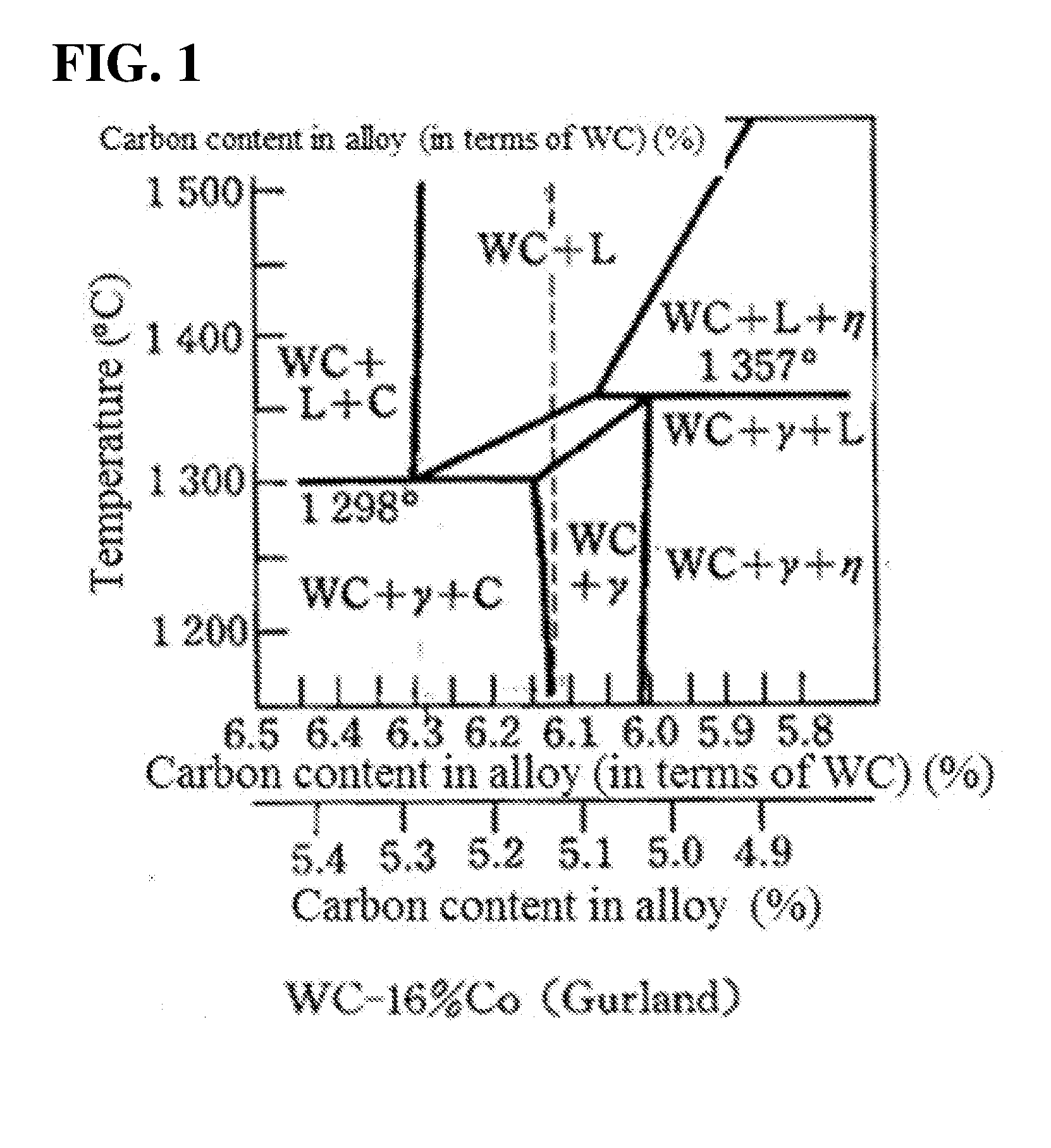
[0118] FIG. 1 illustrates a WC-Co pseudo-binary vertical sectional view (reprinted from Hisashi Suzuki, "Cemented Carbide and Sintered Hard Material" (1986), p. 96, FIG. 1.112 (b), Maruzen Publishing Co., Ltd.).
DESCRIPTION OF EMBODIMENTS
[0119] <Definition of Size of Pore Resulting from Free Carbon, and Measurement Method Thereof>
[0120] The degree of the free carbon generation in the cemented carbide is judged in accordance with C02 to C08 in Appendix 4 of the quality standard CIS006C of Japan Cemented Carbide Tool Manufacturer's Association. When free carbons are generated in a generally produced cemented carbide, the state is as shown in Appendix 4. The grade ranges from C02 that the free carbons are smallest in number and size to C08 that the free carbons are largest in number and size, and even in C02 with the fewest free carbons, the maximum diameter is about 70 .mu.m. As shown in the photograph of the free carbons in Appendix 4, the pore of the free carbon is shaped in such a manner that several small dots aggregate in a dendritic form to form one pore, and the size of this aggregate was measured as the size of the pore. The size of the free carbon pore is generally supposed to be 25 .mu.m or larger (Non-Patent Document 4, p. 283 to 284).
[0121] In the present invention, for measurement of the size of the free carbon pore, a test sample was polished in accordance with the method described in CIS006C, and similarly observed and measured with a 100-power microscope in the same manner as in Appendix 4 of CIS006. In addition, a case that nets resulting from free carbons with a size of 20 .mu.m or larger could not be observed in a visual field (about 0.07.times.0.1 mm) with the same size as in Appendix 4 successively in two visual fields, or a case that 10 visual fields are randomly observed and pores resulting from free carbons with a size of 20 .mu.m or larger could not be observed in 7 visual fields, are defined as cemented carbides with free carbon pores having a maximum diameter of 20 .mu.m or smaller. The cemented carbides with free carbon pores having maximum diameters of 15 .mu.m or smaller and 10 .mu.m or smaller were also determined in the same measurement method.
[0122] However, note that if a pore resulting from free carbons is a small pore of 20 .mu.m or smaller, the pore may be difficult to distinguish from the A-type pore. In order to ascertain whether the pore results from free carbons, it is also necessary to concurrently observe and confirm the pore at a high magnification of several hundreds or higher, as also described in paragraph 0003. In addition, as shown in Tables 2, 4, 6, 7, 8, 9 of Examples, generally chemical analysis (free carbon %) is concurrently carried out, and thus, if there are free carbons, it can be confirmed that the pore results from free carbons.
<Method for Fining Free Carbon>
[0123] FIG. 1 shows a WC-Co pseudo-binary vertical sectional view (reprinted from Hisashi Suzuki, "Cemented Carbide and Sintered Hard Material" (1986), p. 96, FIG. 1.112 (b), Maruzen Publishing Co., Ltd.).
[0124] There are two types of precipitation of free carbons in the cemented carbide. According to FIG. 1,
(1) when the carbon content in the cemented carbide is 6.3% or more in terms of WC, the composition is WC+liquid (L)+carbon (C) at the time of appearance of a liquid phase. When the cemented carbide is cooled and solidified while kept in this composition, the composition is WC+.gamma.+C. (2) when the carbon content is 6.13% to 6.3% in terms of WC, the composition is WC+liquid (L) at the time of appearance of a liquid phase, however when the cemented carbide is cooled while kept in this composition, the composition is WC+.gamma.+C. Since the theoretical carbon content of WC is 6.13%, the content in terms of free carbons is 0.01 to 0.17%.
[0125] Here, .gamma. represents the binder phase mainly composed of Co in the crystal structure fcc (typically referred to as Co phase). The present invention is applied to only in the case of (2). In the case of (1), this range is not generally used for the cemented carbide, because carbons in the liquid phase remain as they are also at the time of appearance of the solid phase, and excessive free carbons are present. However, Patent Document 4 relates to the range of (1), which has been developed for a special application.
[0126] In the case of (2), when the cemented carbide is converted from the liquid phase to the solid phase at a temperature of the melting point or lower, free carbons (C-type pore) precipitate from the liquid phase. The cemented carbide according to the present invention can be realized by finely dispersing the sizes of the precipitated free carbons. Specifically, the cemented carbide is rapidly cooled from the liquid phase to finely disperse precipitation of the free carbons.
[0127] Theoretically, the quicker the rapid cooling is, the finer the free carbons are. However, if the cooling rate is too high, the internal stress may remain and the furnace may deteriorate depending on the product. Hence, there are limits according to the actual circumstances.
[0128] Also, the size of the free carbon is affected not only by the amount of free carbons in the cemented carbide but also by the composition and the shape/size of the sintered compact, and the like.
[0129] Thus, it is desirable to previously select the optimum cooling rate in accordance with the actual circumstance. In terms of facility, a rate of 100.degree. C./min can be sufficiently achieved because of the advanced gas rapid-cooling technology, and examples of 1000.degree. C./min and 10000.degree. C./min have been also reported (Patent Documents 2 and 3). Normally, when the free carbons are examined by a 100-power microscope on the basis of CIS006C, the C-type pore is observed, but when the free carbons are finely dispersed, the pore looks like the A type in some cases. Thus, for ascertaining whether the pore results from free carbons, a method in which the pore is concurrently observed and confirmed at a high magnification of several hundreds or higher is also used, as also described in paragraph 0003. Furthermore, the pore can be confirmed by chemical analysis (free carbon %) as shown in Tables 2, 4, 6, 7, 8, and 9 of Examples.
<Cooling Method>
[0130] For sintering and reheating, vacuum furnaces are normally used. Recently, there have been many vacuum furnaces equipped with a device capable of performing forced cooling with inert gas. It is convenient to use this kind of vacuum furnace for production. The cooling rate can be increased by increasing the gas amount or increasing the gas pressure, and the cooling rate can be controlled depending on the actual circumstance. When a large amount of cemented carbide (product) is charged in a large furnace, the gas amount and the gas pressure should be increased, and when the charged amount is small and the product shape is also small, the gas amount and the gas pressure may be small. The inert gas may be Ar or N.sub.2 gas. The cooling effect of N.sub.2 is slightly larger than that of Ar, and also N.sub.2 is industrially advantageous in respect of cost.
[0131] Hereinafter, the best embodiment for carrying out the present invention will be explained on the basis of Examples. Note that the present invention is not limited to the following embodiments, and known changes can be added to the present invention within a scope substantially equal to or equivalent to the scope of the present invention.
Example 1
[0132] An example of the WC-Co-based material will be described below.
[0133] Mixed powders before sintering were prepared by a process in which commercially available raw materials were blended in the composition of (Table 1), mixed in a wet ball mill in accordance with a common method using alcohol, and dried. Samples with Cr.sub.3C.sub.2 added were designated as A, and samples with no addition were designated as B. In A2 and B2, the carbon contents were larger than that in A1 and B1 by 0.14%, and in B4 and B5, the carbon contents were larger than that in B1 by 0.10% and 0.18% respectively.
TABLE-US-00001 TABLE 1 Added amount Sam- WC(4 .mu.m) Co Cr2C3 of carbon ple (%) (%) (%) (%) A1 84.5 15 0.5 0 A2 84.5 15 0.5 0.14 B1 85 15 0 0 B2 85 15 0 0.14 B4 85 15 0 0.1 B5 85 15 0 0.18
[0134] A lubricant for press was added to these mixed powders, and all powders were pressed at 1 ton/cm.sup.2, and vacuum-sintered. Although the used mixed powders were the same, names of the samples were classified depending on the sintering conditions and heating conditions. The sintering conditions and characteristic values of the samples are shown in (Table 2).
[0135] Here, the "slow cooling" in the sintering conditions refers to a step in which the sample is vacuum-sintered at 1380.degree. C., held for 1 hour, then cooled, and cooled (slowly cooled) from 1350.degree. C. to 800.degree. C. at 10.degree. C./min.
[0136] In addition, the "rapid cooling" in the sintering conditions refers to a step in which the sample is vacuum-sintered at 1380.degree. C., held for 1 hour, then cooled, and cooled (rapidly cooled) from 1350.degree. C. to 800.degree. C. at 30.degree. C./min by introducing an inert gas, and the "strong rapid cooling" refers to a step in which the sample is cooled (strongly and rapidly cooled) from 1350.degree. C. to 800.degree. C. at 50.degree. C./min by introducing an inert gas.
[0137] The "reheating and rapid cooling" in the sintering conditions refers to a step in which the sintered compact is reheated in a vacuum furnace at 1340.degree. C. for 15 minutes, and cooled (rapidly cooled) from 1340.degree. C. to 800.degree. C. at 30.degree. C./min by introducing an inert gas, and the "reheating and strong rapid cooling" refers to a step in which the sintered compact is reheated in a vacuum furnace at 1340.degree. C. for 15 minutes, and cooled (strongly and rapidly cooled) from 1340.degree. C. to 800.degree. C. at 50.degree. C./min.
[0138] Herein, the method for measuring the maximum diameter (.mu.m) of the pore in (Table 2) accords to the above-described <Definition of Size of Pore Resulting from Free Carbon, and Measurement Method Thereof>.
TABLE-US-00002 TABLE 2 Transverse Vickers Maximum Free rupture, hard- diameter Sam- carbon strength ness of pore ple (%) (MPa) (Hv) (.mu.m) Sintering conditions A11 0 3230 1130 10 Slow cooling of A1 A21 0.08 3050 1020 100 Slow cooling of A2 A22 0.05 3200 1110 15 Reheating and rapid cooling of A21 A23 0.06 3220 1110 15 Rapid cooling of A2 B11 0 3200 1110 10 Slow cooling of B1 B21 0.08 3070 1000 100 Slow cooling of B2 B22 0.07 3170 1070 20 Reheating and rapid cooling of B21 B23 0.06 3220 1100 10 Reheating and strong rapid cooling of B21 B24 0.07 3185 1090 15 Rapid cooling of B2 B41 0.06 3090 1020 70 Slow cooling of B4 B42 0.04 3200 1100 10 Reheating and strong rapid cooling of B41 B51 0.12 3000 980 150 Slow cooling of B5 B52 0.1 3160 1070 20 Reheating and rapid cooling of B51
[0139] A11, A21, B11, B21, B41 and B51 are under a sintering condition of "slow cooling". The samples (A11, B11) whose added amount of carbon is 0 in (Table 1) had no free carbon also after sintering, and their pores were evaluated as type A in Appendix 1 of CIS006C, and classified as A02 or lower. The samples (A21, B21, B41, B51) with carbon added had free carbons also after sintering, and their pores were evaluated as type C in Appendix 4 of CIS006C, and classified as C02 to C06.
[0140] In relation to A21 and B21, as described more specifically, powders were sintered, then polished so as to have a mirror surface, and microscopically observed at magnification of 100, and as a result, both samples were evaluated as around C04 in accordance with CIS006C. That is, large free carbon pores of 80 to 100 .mu.m and small free carbon pores of about 25 .mu.m were found in a mixed state in A21 and B21.
[0141] Also, A22 and B22 were prepared by a process in which the A21 and B21 (sintered compact) were reheated in the same vacuum furnace, held at 1340.degree. C. for 15 minutes, cooled, and cooled (rapidly cooled) from 1340.degree. C. to 800.degree. C. at a cooling rate of 30.degree. C./min. The samples were polished by a method according to CIS006C in the same manner as for other samples, and the states of these cemented carbide pores were microscopically observed at magnification of 100.
[0142] The maximum diameter of the pore of A22 was 15 .mu.m or smaller, and the maximum diameter of the pore of B22 was 20 .mu.m or smaller. The transverse rupture strength and the hardness were also measured. A23 and B24 were prepared by a process in which a mixed powder was vacuum-sintered under the same conditions as described above and then cooled (rapidly cooled) at 30.degree. C./min. Also, the mixed powders for B4 and B5 were similarly vacuum-sintered and then cooled. The sintering conditions and the results are shown in (Table 2).
[0143] When A11 and B11 with the sintering condition of "slow cooling" and 0% carbon addition amount were compared with A21 and B21 with the sintering condition of "slow cooling" and 0.14% carbon addition amount, A21 and B21 had a decreased transverse rupture strength and hardness because the free carbons precipitated. However, even if free carbons appear similarly to A22, A23, B22 and B24, the free carbons can be finely dispersed by changing the sintering conditions to "rapid cooling" or "reheating and rapid cooling", and when the pore becomes smaller, the transverse rupture strength becomes equivalent to that of A11 and B11 without free carbons. Also, hardness of A21 and B21 tends to be slightly lower compared to that of A11 and B11 without free carbons, but there is almost no difference.
[0144] B52 had a slightly large amount of pores, and one pore having a maximum diameter of 20 to 25 .mu.m was observed in each of two visual fields out of ten visual fields. B23 was prepared by a process in which B21 is reheated to 1340.degree. C. and strongly and rapidly cooled to 800.degree. C. at 50.degree. C./min, and B23 had pores improved compared to that in B22, the sizes of the pores in B23 were small and all of them were 10 .mu.m or smaller. Also, sizes of all pores in B42 were 10 .mu.m or smaller.
[0145] As described above, normally, when the cemented carbide contains free carbons which cause pores, the produced cemented carbide has low transverse rupture strength and hardness compared to a cemented carbide without free carbons by cooling with a general sintering conditions/cooling method (slow cooling). However, even if the cemented carbide contains free carbons, the free carbon pores in the cemented carbide are dispersed by rapid cooling or strong rapid cooling after sintering, or by slow cooling after sintering and then reheating and rapid cooling or reheating and strong rapid cooling. As a result, a cemented carbide having a transverse rupture strength and a hardness equivalent to those of the cemented carbide without free carbons can be produced.
Example 2
[0146] An example of a material for cutting tools will be described below.
[0147] Mixed powders before sintering were prepared by a process in which commercial raw materials were blended in the composition of (Table 3), subjected to a wet ball milling and dried in accordance with a general method using alcohol. A lubricant for press was added to all of these mixed powders, which were pressed at 1 ton/cm.sup.2. C11 and C21 were vacuum-sintered at 1400.degree. C., held for 1 hour, then cooled, and cooled (slowly cooled) from 1380.degree. C. to 800.degree. C. at 10.degree. C./min (corresponding to "slow cooling" in the sintering conditions).
[0148] On the other hand, C23 was vacuum-sintered at 1400.degree. C., held for 1 hour, then cooled, and cooled (strongly and rapidly cooled) from 1380.degree. C. to 800.degree. C. at 50.degree. C./min by introducing an inert gas (corresponding to "strong rapid cooling" in the sintering conditions).
[0149] In addition, C22 is prepared by reheating and rapidly cooling C21. The "reheating and rapid cooling" in the sintering conditions refers to a step in which the sample is held in a vacuum furnace at 1380.degree. C. for 30 minutes and cooled at 30.degree. C./min. C22 did not have pores with sizes of 20 .mu.m or larger. The sizes of the pores in C23 were 10 .mu.m or smaller. The results are shown in Table 4.
TABLE-US-00003 TABLE 3 WC (2 .mu.m) Co TiC TaNbC Cr2C3 Added amount Sample (%) (%) (%) (%) (%) of carbon (%) C1 73 10 8.5 8.5 0 0 C2 73 10 8.5 8.5 0 0.22
TABLE-US-00004 TABLE 4 Transverse Vickers Maximum Free rupture hard- diameter Sam- carbon strength ness of pore ple (%) (MPa) (Hv) (.mu.m) Sintering condition C11 0 2195 1470 10 Slow cooling of C1 C21 0.08 2040 1400 90 Slow cooling of C2 C22 0.1 2150 1430 20 Reheating and rapid cooling of C21 C23 0.06 2190 1460 10 Strong rapid cooling of C2.
[0150] In addition, C11, C21, C22 and C23 as base materials were CVD-coated with TiC with a thickness of 7 .mu.m. C11 had an .eta. phase with a thickness of 1 to 3 .mu.m at the boundary between the TiC coat and the base material, but C21 had no .eta. phase. Data for verifying Non-Patent Document 3 was obtained. Also C22 and C23 had no .eta. phase at the boundary between the TiC coat and the base material, and the same result as for C21 was obtained. That is, even if free carbons are finely dispersed in the base material, the effect for reducing the .eta. phase is same.
Example 3
[0151] An example of a cemented carbide having a .beta.-free layer on its surface, which is frequently used for a CVD base material will be described below.
TABLE-US-00005 TABLE 5 WC Co TiC TaNbC TiN Added amount Sample (%) (%) (%) (%) (%) of carbon (%) E 87.5 5 2 5 0.5 0 F 87.5 5 2 5 0.5 0.18
TABLE-US-00006 TABLE 6 Transverse Vickers Maximum Free rupture hard- diameter Sam- carbon strength ness of pore ple (%) (MPa) (Hv) (.mu.m) Sintering conditions E1 0 -- 1510 10 Slow cooling of E F1 0.1 -- 1440 90 Slow cooling of F F2 0.07 -- 1490 15 Rapid cooling of F
[0152] Mixed powders before sintering were prepared by a process in which commercial raw materials were blended in the composition of (Table 5), mixed in a wet ball mill and dried in accordance with a general method using alcohol. A lubricant for press was added to these mixed powders, all of which were pressed at 1 ton/cm.sup.2. E1 and F1 were vacuum-sintered at 1400.degree. C., held for 1 hour, then cooled, and cooled (slowly cooled) from 1380.degree. C. to 800.degree. C. at 10.degree. C./min (corresponding to "slow cooling" in the sintering conditions).
[0153] On the other hand, F2 was vacuum-sintered at 1400.degree. C., held for 1 hour, then cooled, and cooled (rapidly cooled) from 1380.degree. C. to 800.degree. C. at 30.degree. C./min by introducing an inert gas (corresponding to "rapid cooling" in the sintering conditions). The results are shown in (Table 6). All of the samples E1, F1 and F2 had the .beta.-free layer with a thickness of 10 to 20 .mu.m on the surface. Even if the free carbons are finely dispersed, the .beta.-free layer can be made. These samples had .beta.-free layers on their sintered surface, and the transverse rupture strength was not measured.
Example 4
[0154] Experiments on the dimensional accuracy of the edge replacement-type cutting tip were carried out.
[0155] A lubricant for press was added to mixed powders of C1 and C2 in (Table 3) in Example 2, which was pressed at 1 ton/cm.sup.2 into a plurality of edge replacement-type cutting tips model no. SNMA432, sintered, and dimensional accuracy was measured. Results in (Table 7) were obtained. The sintering conditions are the same between G11 and C11, between G21 and C21, between G22 and C22, between G23 and C23.
[0156] The "dimensional difference inside the tip" in (Table 7) refers to a difference between the maximum value and the minimum value when four sides of one SNMA432 (square) are measured with a micrometer.
[0157] The "difference between maximum and minimum values in 10 samples" in (Table 7) refers to a value obtained by subtracting the minimum value from the maximum value when four sides of ten SNMA432s are measured.
TABLE-US-00007 TABLE 7 Difference between Maximum Dimensional maximum and minimum Sample Free diameter difference dimensions in (model no. carbon of pore inside the tip 10 samples SNMA432) Sintering condition (%) (.mu.m) (mm) (mm) G11 Slow cooling of C1 0 10 0.07 0.12 G21 Slow cooling of C2 0.08 90 0.05 0.09 G22 Reheating and rapid 0.1 20 0.05 0.09 coding of G21 G23 Strong rapid cooling 0.08 10 0.04 0.07 of C2
[0158] In G22 and G23 having finely dispersed free carbons, dimensional unevenness is smaller than that in G11 without free carbons.
[0159] G11, G22 and G23 were coated with 2 .mu.m TiC.sub.2+3 .mu.m TiN by ion plating which is one type of PVD, and subjected to the same measurement. Both the PVD-coated G22, G23 and the PVD-coated G11 had the same dimensional difference inside the tip and difference between maximum and minimum values in 10 samples as those before the coating. The coated G22 and G23 had smaller dimensional unevenness than that of the coated G11.
[0160] Furthermore, G11, G22, G23 were coated with TiC with a thickness of 7 .mu.m by a CVD method, and subjected to the same dimensional measurement for comparison. As expected, the dimensional unevenness was almost the same as before coating, and the coated G22 and G23 had smaller dimensional unevenness than that of G11.
Example 5
[0161] Cylindrical cemented carbide sintered compacts were prepared, and compared and investigated for the dimensional accuracy.
[0162] A lubricant for press was added to mixed powders of B1, B2 and B4 in Example 1, and pressed at 1 ton/cm.sup.2 to prepare a plurality of sintered compacts having an outer diameter of 50D, an inner diameter of 20d and a height of 50 (unit: mm), and compared for the dimensional accuracy. The results are shown in (Table 8).
TABLE-US-00008 TABLE 8 Dimensional Difference between Maximum difference in maximumand minimum Sample Free diameter one sintered outer diameters Cylindrical carbon of pore compact in 3 samples product Sintering condition (%) (.mu.m) (mm) (mm) H11 Slow cooling of B1 0 10 0.5 0.7 H21 Slow cooling of B2 0.08 100 0.3 0.4 H24 Rapid cooling of B2 0.07 15 0.2 0.3 H41 Slow cooling of B4 0.06 70 0.25 0.3 H42 Reheating and strong 0.06 10 0.2 0.25 rapid cooling of H41
[0163] The sintering conditions took over those for the B1, B2 and B4 powders. In the dimensional measurement, the outer diameter of the sintered compact was measured, and the difference between the maximum diameter and the minimum diameter was determined in order to judge whether or not the dimensional accuracy was good. The difference between the maximum and minimum outer diameters of one sintered compact, and the difference between the maximum and minimum diameters of three sintered compacts were indicated. It can be seen that H24 and H42 having finely dispersed free carbons have better dimensional accuracy than that of H11 without free carbons.
Examples 6
[0164] The machining efficiencies in preparing cemented carbide machined products were compared.
[0165] Circumferences of H11 and H24 in (Example 5) as work materials were cut by a lathe. As a cutting tool, model no. TNGA432 of a polycrystalline diamond sintered compact was used. Cutting was carried out under a condition of cutting velocity (v)=15 m/min, feeding rate (f)=0.1 mm/rev and cutting depth (d)=0.1 mm.
[0166] In relation to the time to remove the sintered skin on the circumference, naturally, H11 having many distortions and large stock allowance required 1.5 times more time than H24 with less distortion.
[0167] Furthermore, in order to compare the machinability between H11 and H24, the sintered skin was removed, then the tool was changed with a new tool, cutting was performed for 20 minutes under the same condition, and progress states of wear were compared between the both tools.
[0168] An amount of the tool wear (flank wear) due to cutting of H11 was 0.11 mm, and in the case of H24, it was 0.08 mm. This indicates that H24 has better machinability than that of H11. That is, the cemented carbide according to the present invention has not only a good dimensional accuracy for the sintered compact, but also an excellent machinability. Consequently, it was confirmed that cemented carbide machined products with low machining cost could be provided.
Example 7
[0169] The relationship between the lattice constant of the fcc in the binder phase (Co phase) and the cutting performance was investigated.
[0170] The C1 powder in (Example 2) was pressed into the SNMA432 at 1 ton/cm.sup.2, vacuum-sintered at 1400.degree. C., held for 1 hour, and then rapidly cooled (very strongly and rapidly cooled) at a cooling rate of 70.degree. C./min. The sample was numbered as G24. Also in (Example 4), the mixed powder was the same as in (Example 2), and as samples, G11, G21, G22 and G23 in (Example 4) and the above G24 were used, and compared for the lattice constant and the cutting performance. X-ray diffraction using Cu as the target was used for measuring the lattice constant.
TABLE-US-00009 TABLE 9 Sample Maximum Lattice Flank Shear drop on rake face (model no. Free carbon diameter of constant wear of coated cemented SNMA432) Sintering condition (%) pore (.mu.m) (.ANG.) (mm) carbide (mm) G11 Slow cooling of C1 0 10 3.555 0.4 0.025 G21 Slow cooling of C2 0.08 90 3.55 0.55 0.034 G22 Reheating and 0.1 20 3.562 0.35 0.023 rapid cooling of C21 G23 Strong rapid 0.08 10 3.568 0.25 0.02 cooling of C2 G24 Very strong rapid 0.06 10 3.571 0.2 0.016 cooling of C2
[0171] The flank wear of the tip was measured under a cutting (lathe cutting) condition of work material: SCM3, cutting velocity v=120 m/min, feeding rate f=0.4 mm/rev, cutting depth d=2 mm, and cutting time t=30 min.
[0172] Furthermore, G11, G21 to G24 were PVD-coated with 2 .mu.m TiC+3 .mu.m TiN, and subjected to a cutting test. Under a cutting (lathe cutting) condition of work material: SK5, v=100 m/min, f=0.5 mm/rev, d=2 mm, and t=30 min, the coated cemented carbides using G11, G21 to G24 were compared for the level of plastic deformation (shear drop on edge rake face) of the blade after test. The results are shown in (Table 9).
[0173] The performance of G21 containing free carbons in the conventional form was inferior to that of G11. However, it is found that both the cemented carbide and coated cemented carbide having a high lattice constant and finely dispersed free carbons are naturally superior to G21, but they are superior to G11 without free carbons.
* * * * *
D00001
XML
uspto.report is an independent third-party trademark research tool that is not affiliated, endorsed, or sponsored by the United States Patent and Trademark Office (USPTO) or any other governmental organization. The information provided by uspto.report is based on publicly available data at the time of writing and is intended for informational purposes only.
While we strive to provide accurate and up-to-date information, we do not guarantee the accuracy, completeness, reliability, or suitability of the information displayed on this site. The use of this site is at your own risk. Any reliance you place on such information is therefore strictly at your own risk.
All official trademark data, including owner information, should be verified by visiting the official USPTO website at www.uspto.gov. This site is not intended to replace professional legal advice and should not be used as a substitute for consulting with a legal professional who is knowledgeable about trademark law.