Sheet Pressing Mechanism And Image Forming Apparatus
ITAGAKI; YUUSUKE ; et al.
U.S. patent application number 16/184569 was filed with the patent office on 2019-05-16 for sheet pressing mechanism and image forming apparatus. The applicant listed for this patent is SHARP KABUSHIKI KAISHA. Invention is credited to TATSUFUMI ATSUMI, MASAHIKO FUJITA, YUUSUKE ITAGAKI.
| Application Number | 20190144232 16/184569 |
| Document ID | / |
| Family ID | 66433101 |
| Filed Date | 2019-05-16 |


View All Diagrams
| United States Patent Application | 20190144232 |
| Kind Code | A1 |
| ITAGAKI; YUUSUKE ; et al. | May 16, 2019 |
SHEET PRESSING MECHANISM AND IMAGE FORMING APPARATUS
Abstract
A sheet pressing mechanism includes a pressing member configured to press a sheet that has been deformed to corrugate in a width direction that is orthogonal to a sheet discharging direction when the sheet is discharged toward a discharge tray. The pressing member has a first pressing area for pressing portions other than a top portion of a crest of the sheet when the discharged sheet comes into contact with the pressing member.
| Inventors: | ITAGAKI; YUUSUKE; (Sakai City, JP) ; FUJITA; MASAHIKO; (Sakai City, JP) ; ATSUMI; TATSUFUMI; (Sakai City, JP) | ||||||||||
| Applicant: |
|
||||||||||
|---|---|---|---|---|---|---|---|---|---|---|---|
| Family ID: | 66433101 | ||||||||||
| Appl. No.: | 16/184569 | ||||||||||
| Filed: | November 8, 2018 |
| Current U.S. Class: | 271/188 |
| Current CPC Class: | B65H 31/26 20130101; B65H 2405/11151 20130101; B65H 2404/61 20130101; B65H 2301/4212 20130101; B65H 29/14 20130101; B65H 29/125 20130101; B65H 2405/1111 20130101; B65H 2301/5122 20130101; B65H 31/00 20130101; B65H 31/02 20130101; B65H 29/70 20130101; B65H 2404/63 20130101; B65H 2801/06 20130101; B65H 37/06 20130101 |
| International Class: | B65H 37/06 20060101 B65H037/06; B65H 31/00 20060101 B65H031/00; B65H 29/14 20060101 B65H029/14 |
Foreign Application Data
| Date | Code | Application Number |
|---|---|---|
| Nov 10, 2017 | JP | 2017-217636 |
Claims
1. A sheet pressing mechanism comprising: a pressing member configured to press a sheet that has been deformed to corrugate in a width direction that is orthogonal to a sheet discharging direction when the sheet is discharged toward a discharge tray, wherein the pressing member has a first pressing area for pressing portions other than a top portion of a crest of the sheet when the discharged sheet comes into contact with the pressing member.
2. The sheet pressing mechanism according to claim 1, wherein the pressing member has a second pressing area for pressing a central area of the sheet in the width direction when the sheet is brought into contact with the discharge tray.
3. The sheet pressing mechanism according to claim 1, wherein the first pressing area presses two or more portions other than the top portion of the crest of the sheet when the discharged sheet comes into contact with the pressing member.
4. The sheet pressing mechanism according to claim 1, wherein the pressing member has a pair of pressing sections for pressing two portions other than the top portion of the crest of the sheet when the discharged sheet comes into contact with the pressing member and a connection section that connects tip sections of the pair of pressing sections.
5. The sheet pressing mechanism according to claim 1, wherein the pressing member has a substantially U-shape in which a downstream side viewed from a vertical direction is curved in the sheet discharging direction.
6. The sheet pressing mechanism according to claim 1, wherein the pressing member is configured to rotate about an axis along the width direction.
7. An image forming apparatus comprising the sheet mechanism according to claim 1.
8. The image forming apparatus according to claim 7, wherein the discharge tray includes a first tray section and a second tray section that is continuously connected to the downstream side of the first tray section in the sheet discharging direction, the first tray section is inclined such that the downstream side is higher than an upstream side, the second tray section is disposed in a horizontal position, or in a substantially horizontal position, or inclined such that the downstream side is higher than the upstream side at an angle smaller than the angle of the first tray section, and the first pressing area in the pressing member extends to an area corresponding to the second tray section in the sheet discharging direction when the sheet is brought into contact with the discharge tray.
Description
BACKGROUND
1. Field
[0001] The present disclosure relates a sheet pressing mechanism and an image forming apparatus such as a copying machine, a multifunction peripheral, a printing apparatus, and a facsimile apparatus.
2. Description of the Related Art
[0002] Some image forming apparatuses are provided with a sheet pressing mechanism having a pressing member for pressing a sheet such as paper that is discharged toward a discharge tray (see Japanese Unexamined Patent Application Publication No. 2014-47067).
[0003] In discharging a sheet onto a discharge tray, if the leading edge of the sheet comes into contact with an upstream side (base end side) of the discharge tray, the following problem may occur. For example, the sheet may be discharged onto the discharge tray while moving on the discharge tray with its leading edge in contact with the upstream side of the discharge tray. In such a state, if the leading edge of the sheet fails to smoothly move on the discharge tray, the sheet may be discharged onto the discharge tray in a state in which the sheet is bent with the leading edge facing downward.
[0004] In view of the above, some known image forming apparatuses corrugate a sheet in a width direction that is orthogonal to the sheet discharging direction to deform the sheet. With this deformation, the leading edge of the sheet can be brought into contact with the downstream side (tip side) of the discharge tray. Consequently, for example, the risk of the sheet being discharged onto the discharge tray in the bent state can be effectively reduced.
[0005] If the discharged sheet comes into contact with a pressing member, however, depending on the contact position of the sheet with the pressing member, the deformation of the sheet may be released, that is, the corrugations of the sheet may be released. In such a state, the leading edge of the sheet may not be brought into contact with the downstream side of the discharge tray.
[0006] Japanese Unexamined Patent Application Publication No. 2014-47067 suggests nothing about the release of deformation of a sheet due to the discharged sheet coming into contact with the pressing member.
SUMMARY
[0007] It is desirable to provide a sheet pressing mechanism and an image forming apparatus capable of reduce the release of deformation of a sheet due to the discharged sheet coming into contact with a pressing member to reduce, for example, the risk of the sheet being discharged onto a discharge tray in a bent state with its leading edge facing downward.
[0008] According to an aspect of the disclosure, there is provided a sheet pressing mechanism that includes a pressing member configured to press a sheet that has been deformed to corrugate in a width direction that is orthogonal to a sheet discharging direction when the sheet is discharged toward a discharge tray. The pressing member has a first pressing area for pressing portions other than a top portion of a crest of the sheet when the discharged sheet comes into contact with the pressing member. An image forming apparatus according to an aspect of the disclosure includes the sheet pressing mechanism according to an aspect of the disclosure.
[0009] According to the disclosure, the release of deformation of a sheet due to the discharged sheet coming into contact with a pressing member can be reduced, and thereby the risk of the sheet being discharged onto a discharge tray in a bent state with its leading edge facing downward can be effectively reduced.
BRIEF DESCRIPTION OF THE DRAWINGS
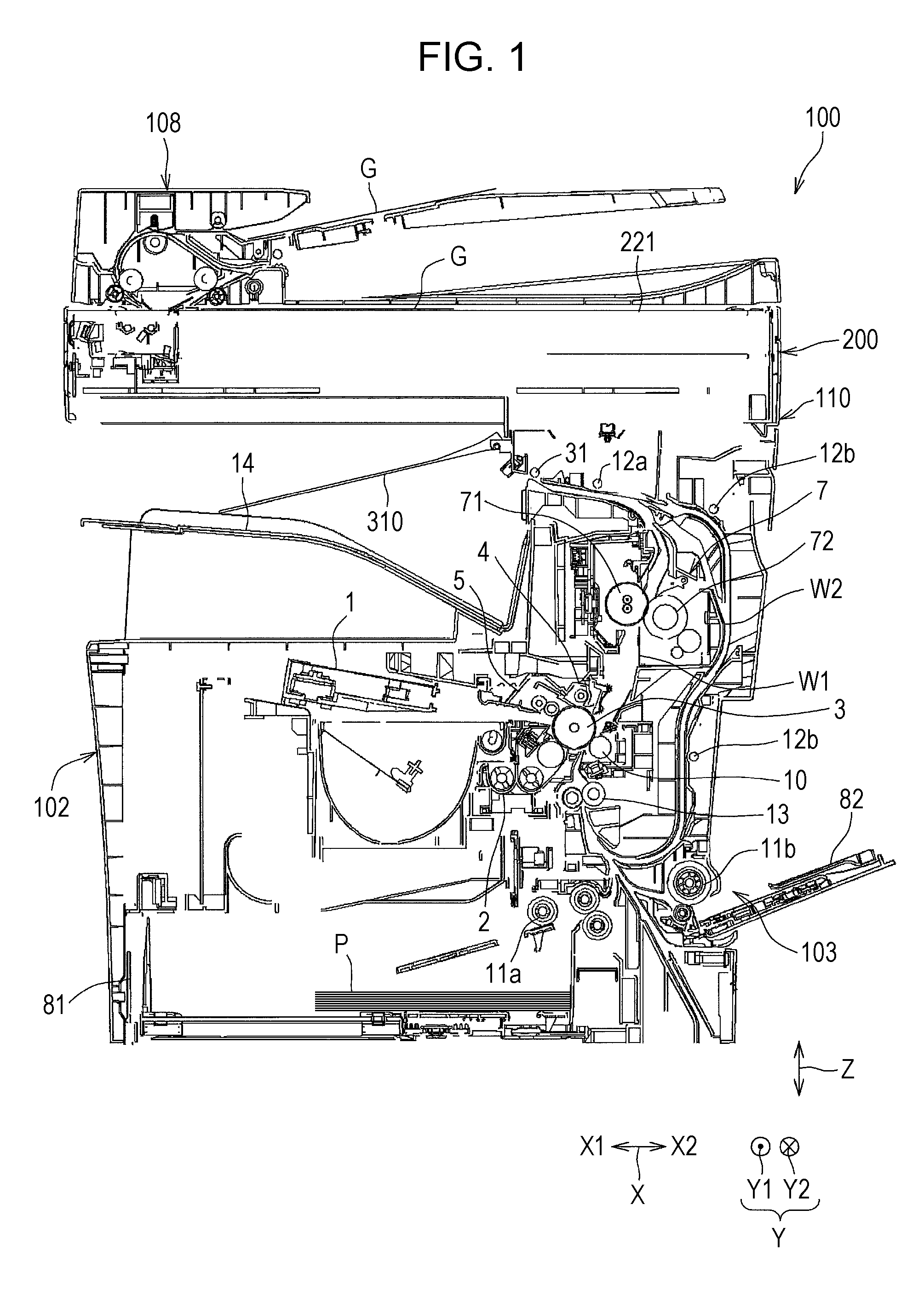
[0010] FIG. 1 is a schematic cross-sectional view illustrating an image forming apparatus according to an embodiment in front view;
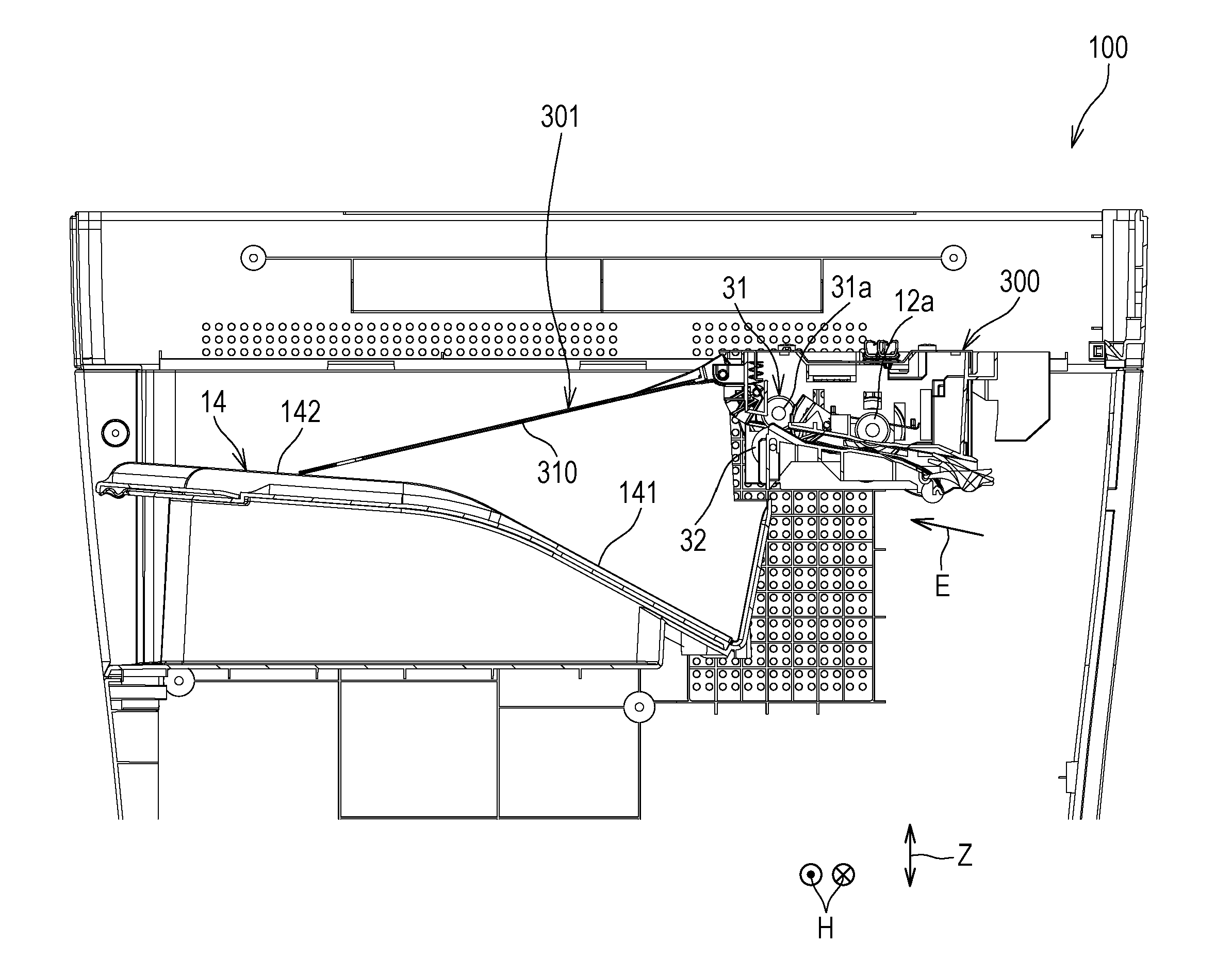
[0011] FIG. 2 is a cross-sectional view illustrating a sheet discharge device in the image forming apparatus;
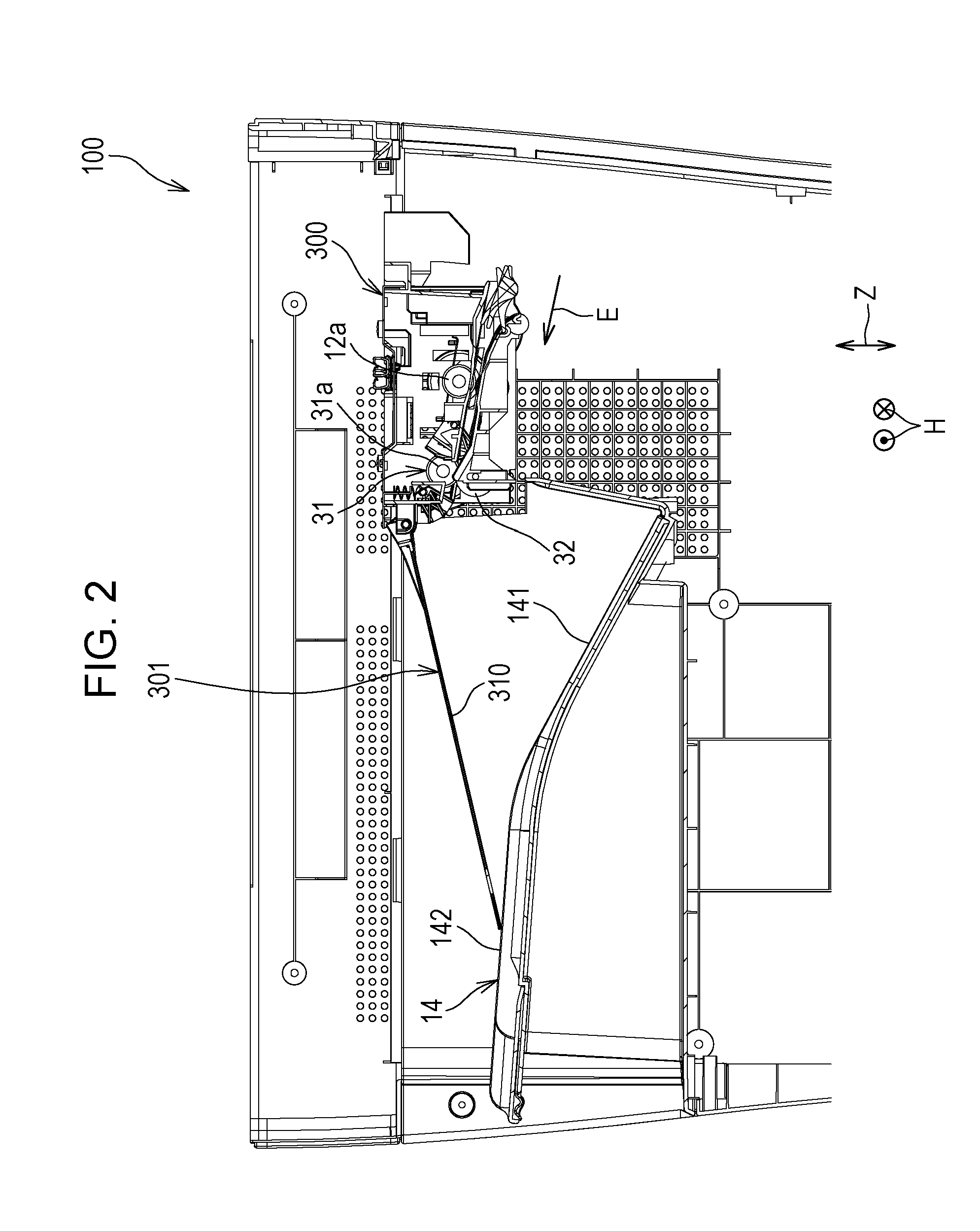
[0012] FIG. 3 is a perspective view illustrating a discharge side of the sheet discharge device in the image forming apparatus viewed diagonally from above;
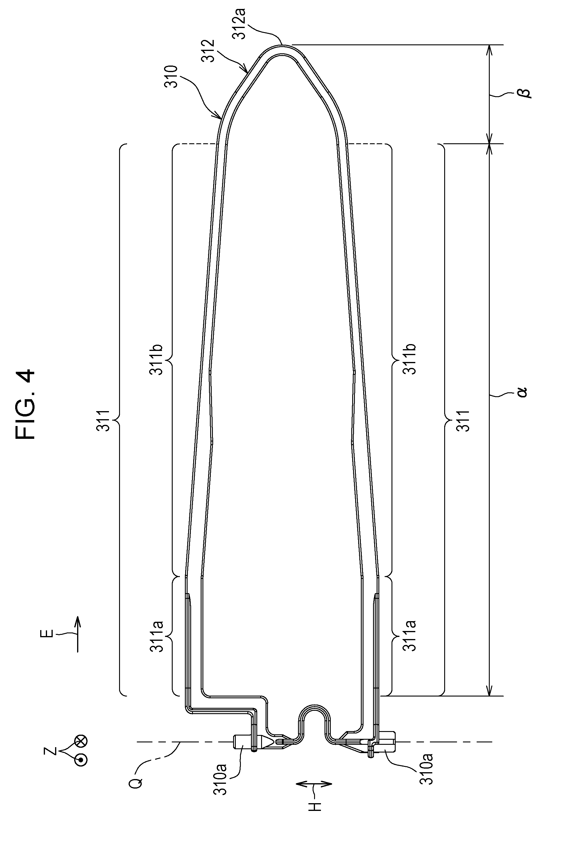
[0013] FIG. 4 is a plan view illustrating a pressing member in a sheet pressing mechanism in the sheet discharge device;
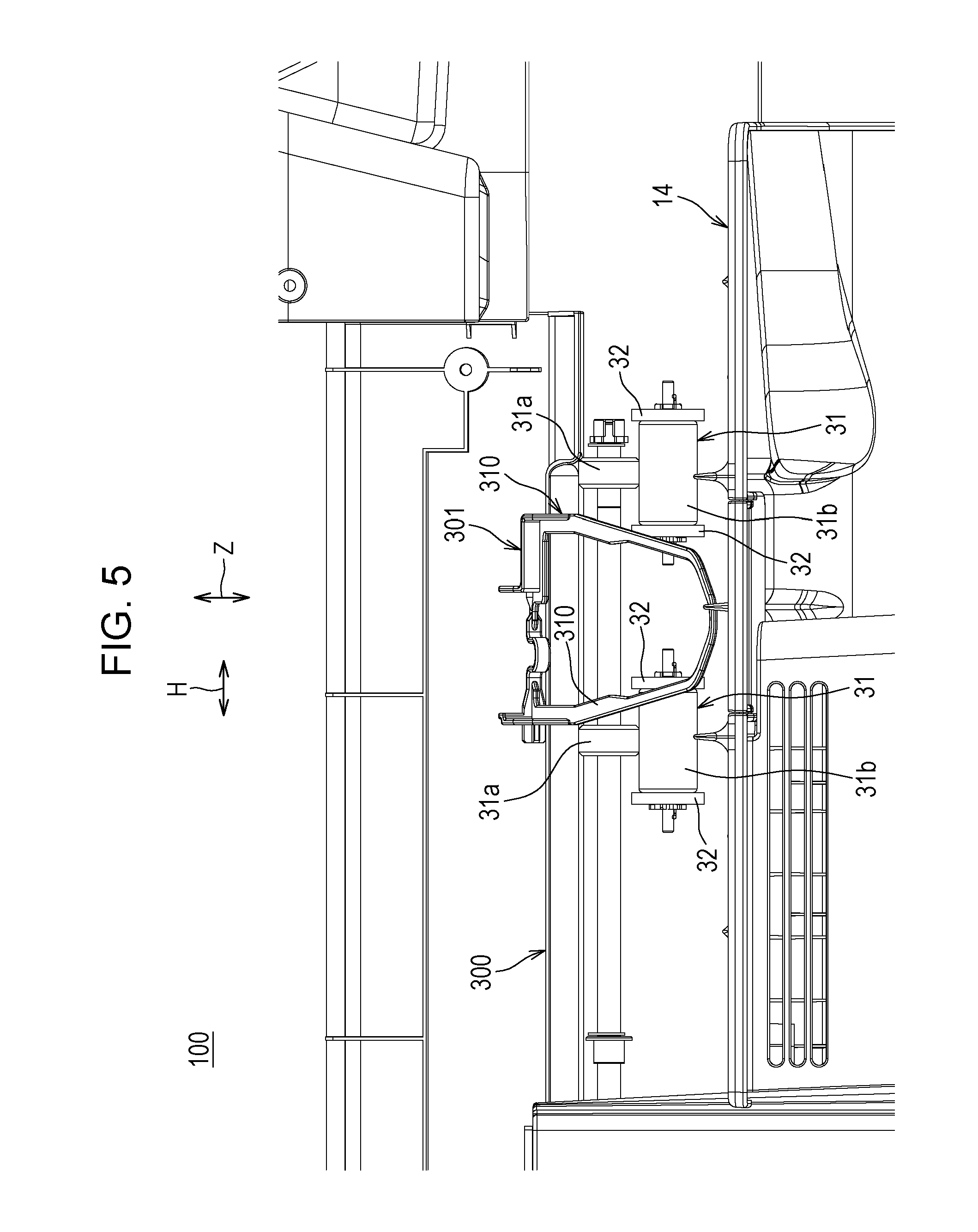
[0014] FIG. 5 is a side view illustrating main components of the sheet discharge device in the image forming apparatus viewed from the discharge side;
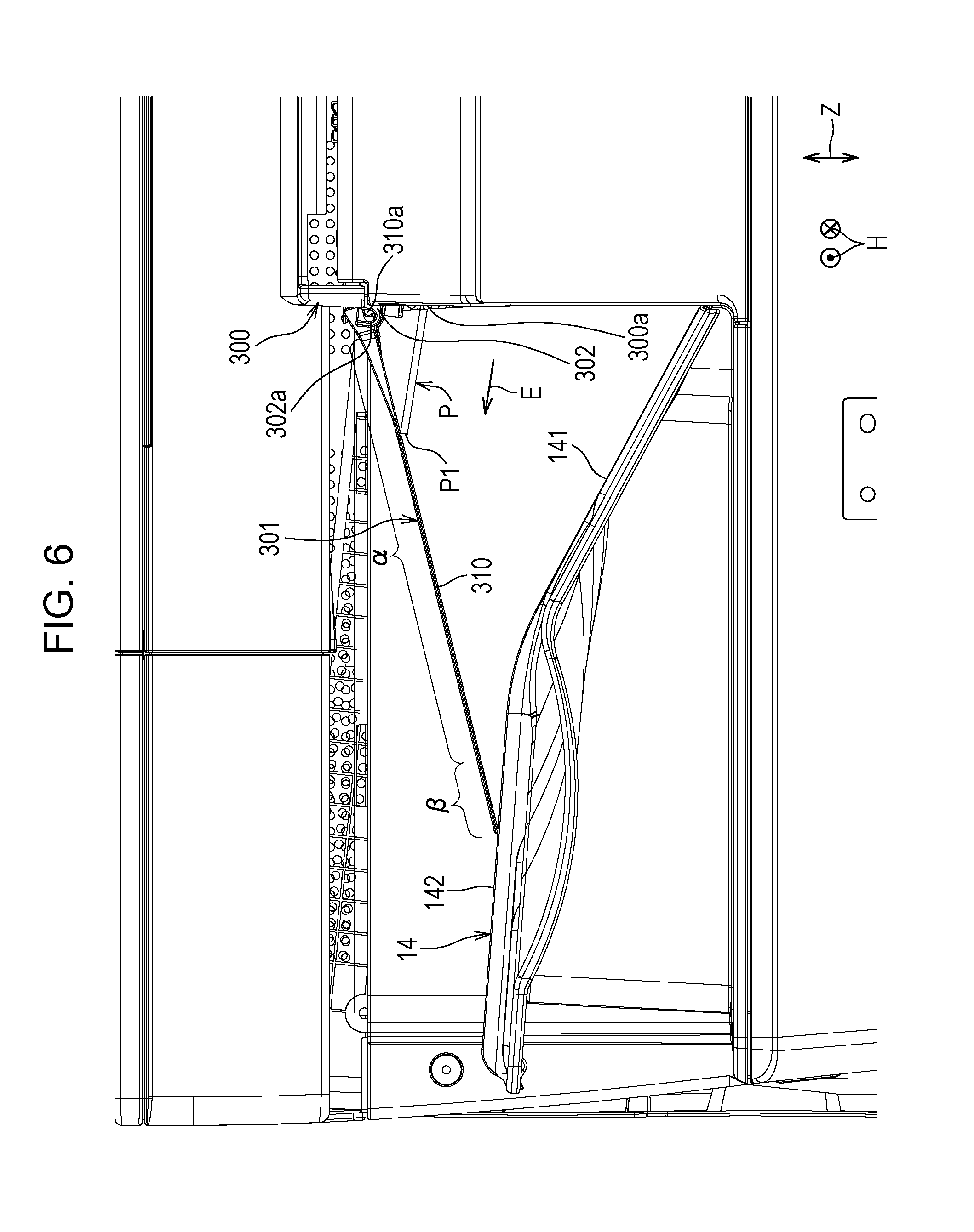
[0015] FIG. 6 is a front view illustrating a state in which a leading edge of a sheet is discharged from a discharge port of the sheet discharge device and comes into contact with a first pressing area of the pressing member;
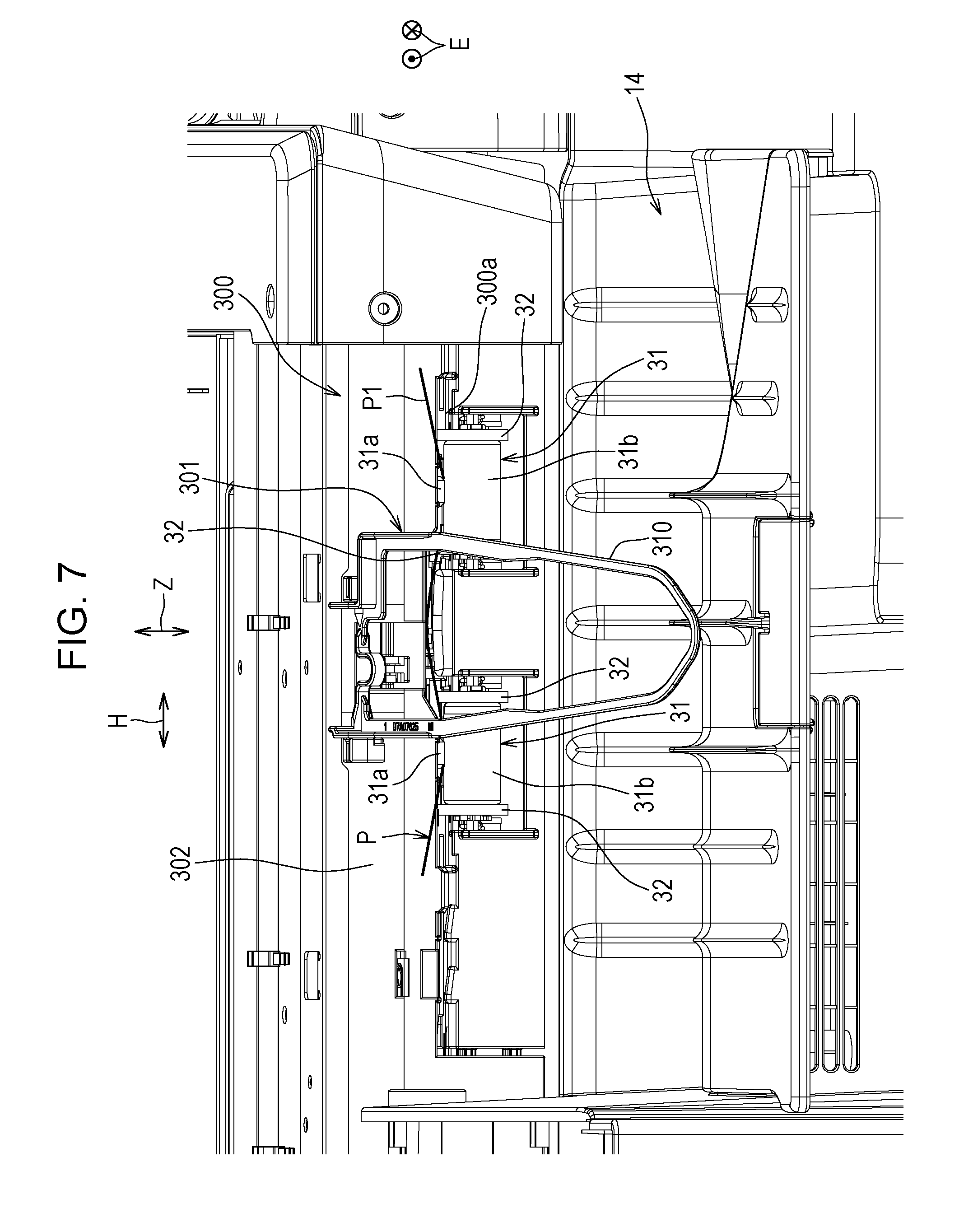
[0016] FIG. 7 is a side view illustrating the state in FIG. 6 viewed from the sheet discharging direction;
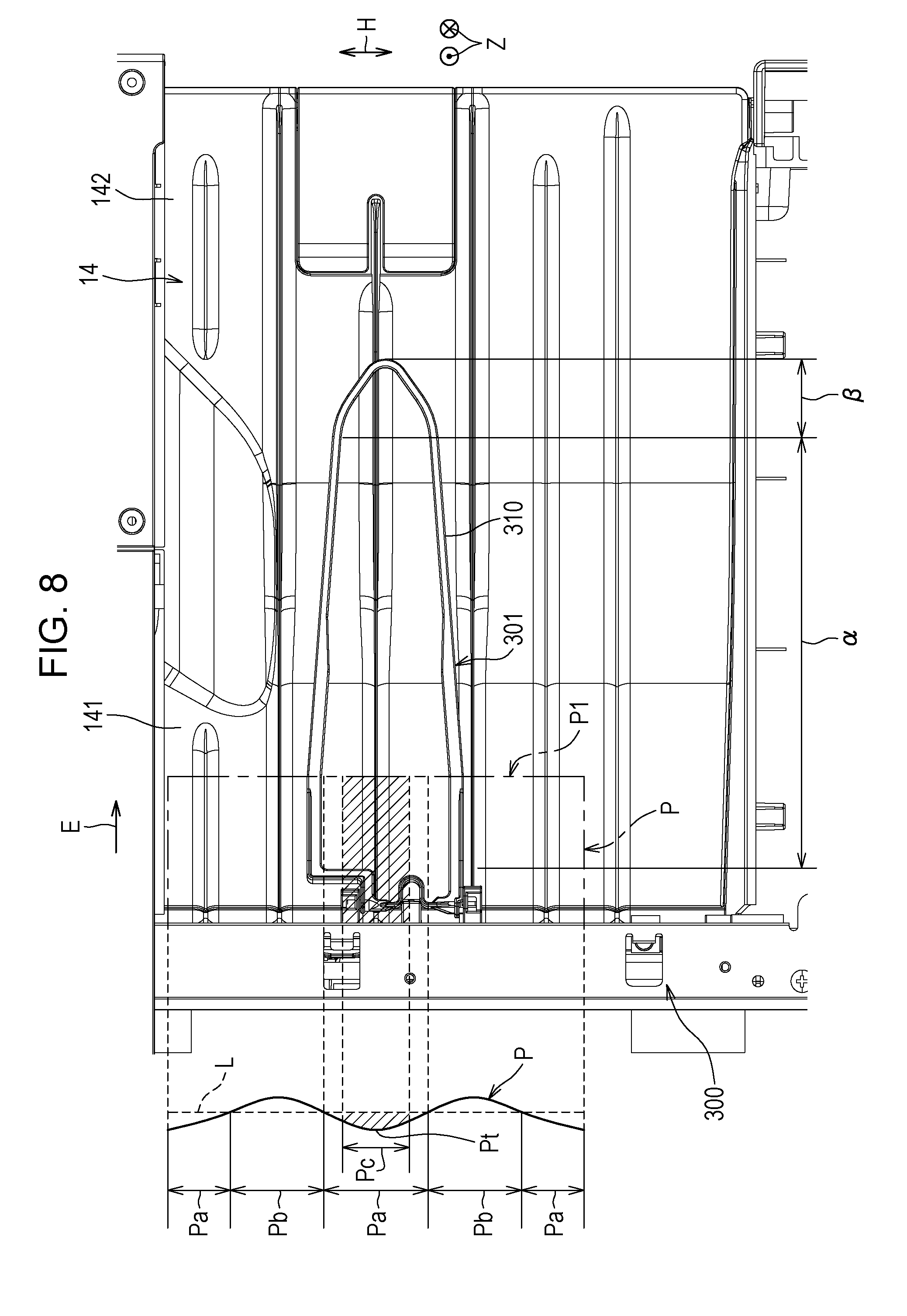
[0017] FIG. 8 is a plan view illustrating the state in FIG. 6;
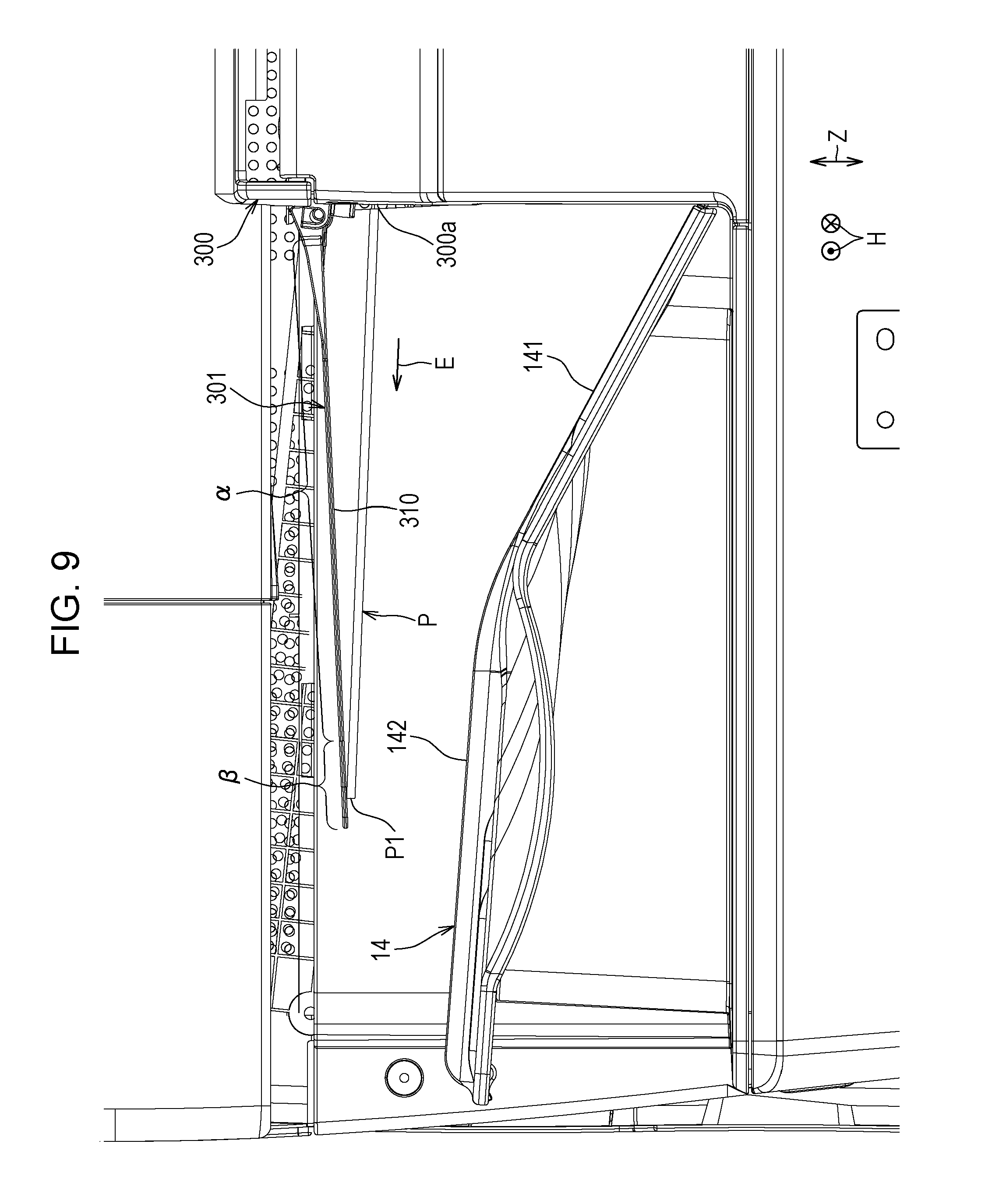
[0018] FIG. 9 is a front view illustrating a state in which the leading edge of the sheet reaches a second pressing area of the pressing member;
[0019] FIG. 10 is a side view illustrating the state in FIG. 9 viewed from the sheet discharging direction;
[0020] FIG. 11 is a plan view illustrating the state in FIG. 9;
[0021] FIG. 12 is a front view illustrating a state in which the leading edge of the sheet comes into contact with the discharge tray;
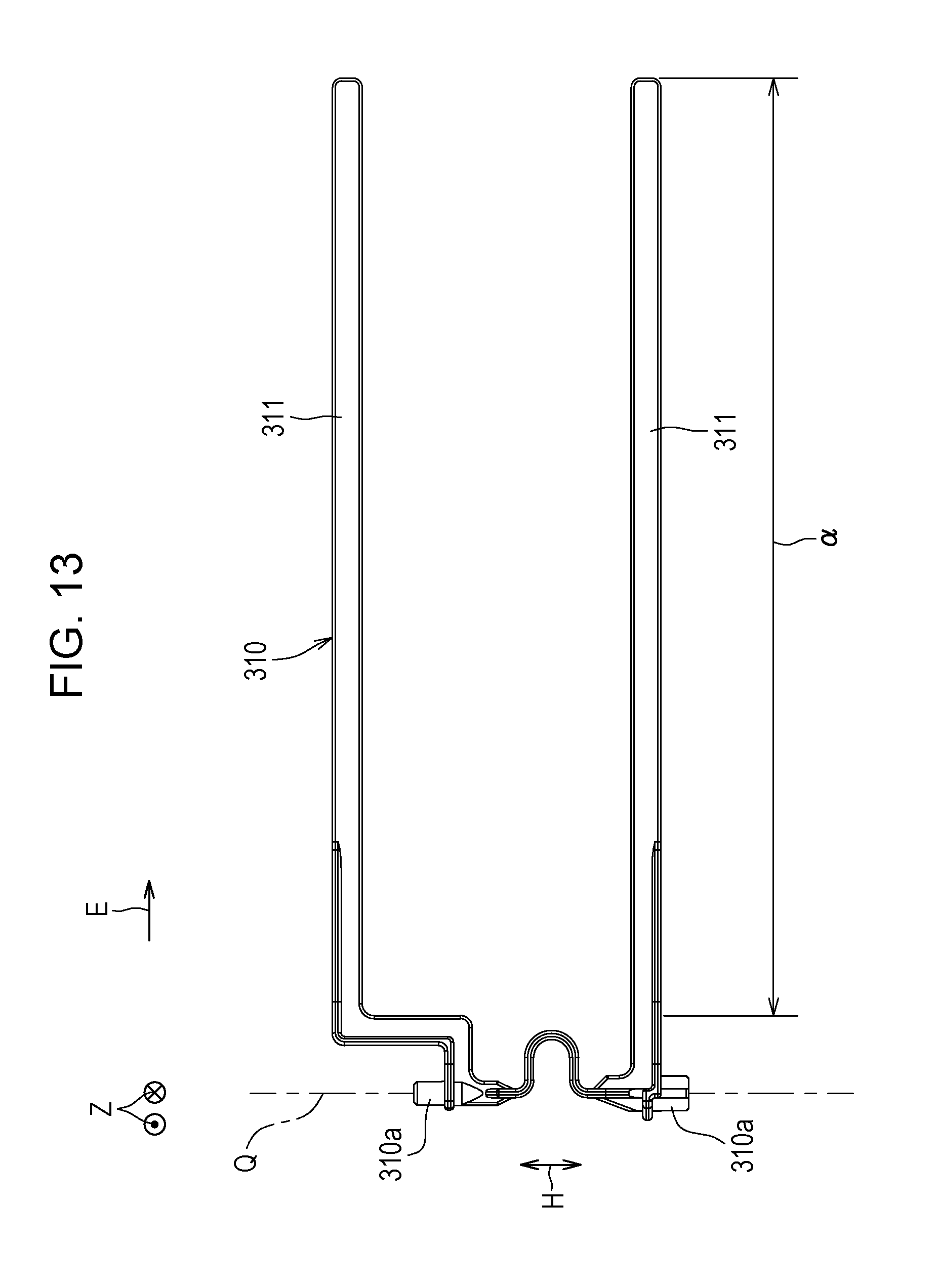
[0022] FIG. 13 is a plan view illustrating another example pressing member;
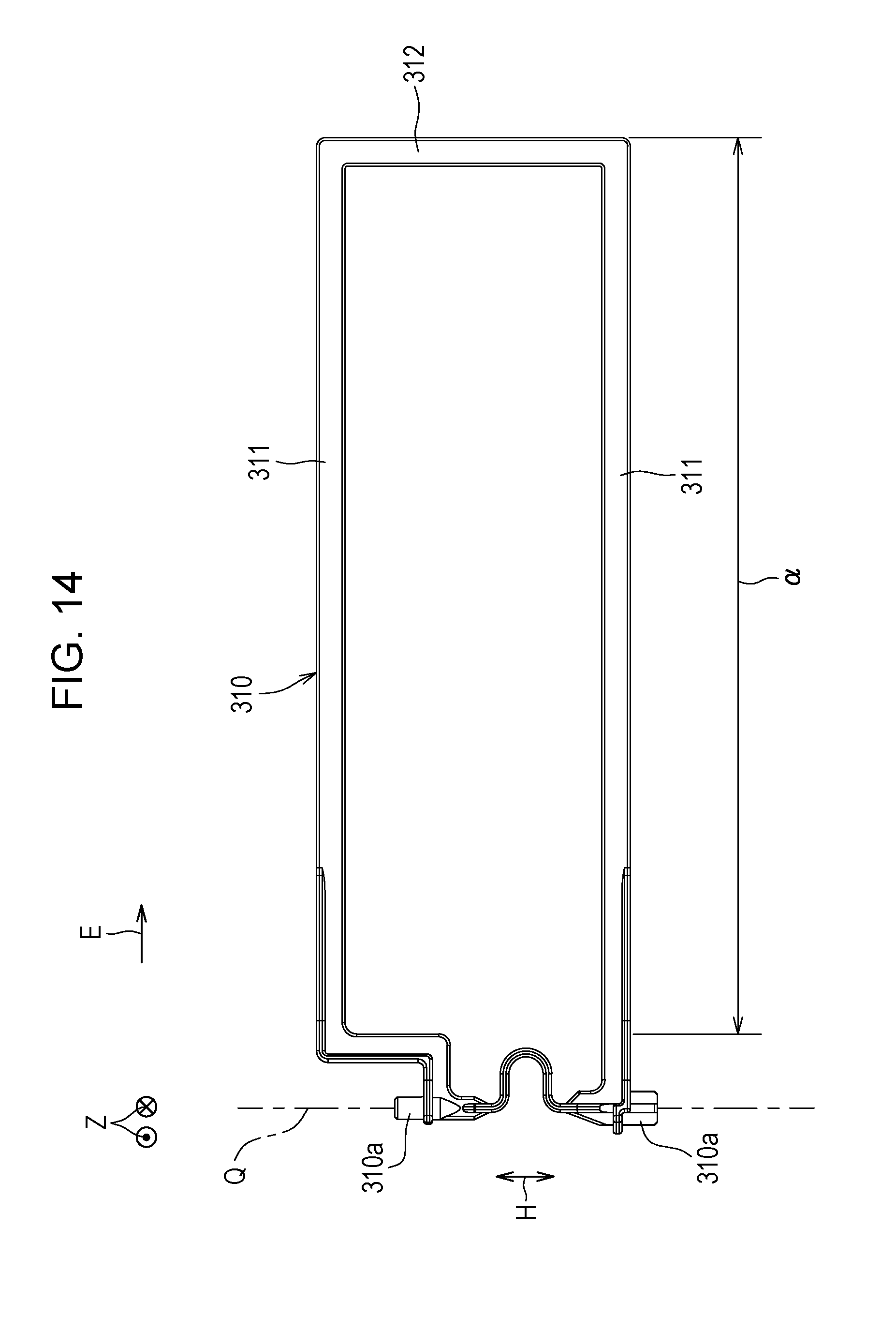
[0023] FIG. 14 is a plan view illustrating still another example pressing member; and
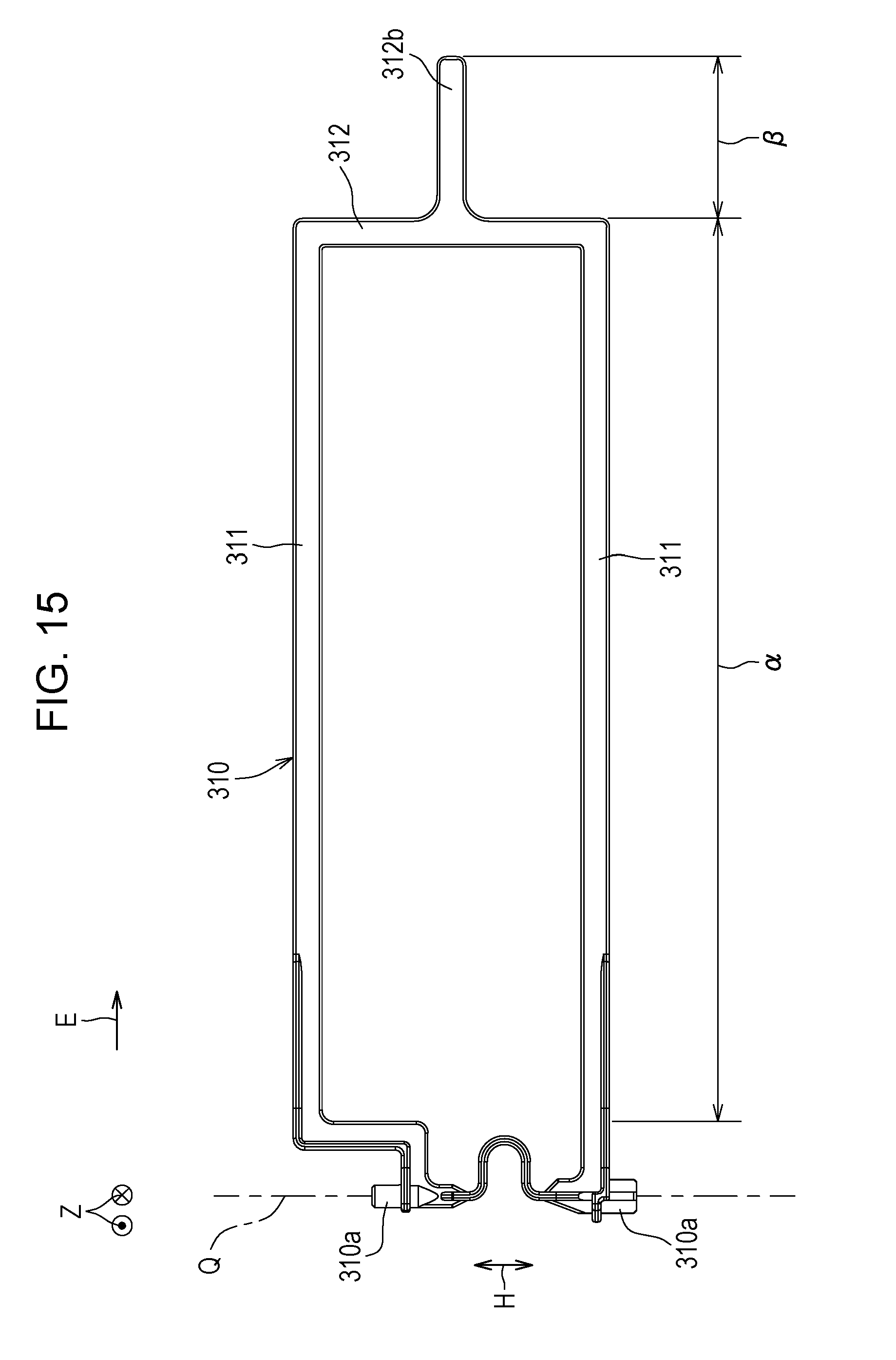
[0024] FIG. 15 is a plan view illustrating still yet another example pressing member.
DESCRIPTION OF THE EMBODIMENTS
[0025] Hereinafter, embodiments of the disclosure will be described with reference to the attached drawings. In the following descriptions, to the same components, the same reference numerals are given. The names and functions of the components denoted by the reference numerals are the same. Consequently, detailed descriptions of the components will not be repeated.
Image Forming Apparatus
[0026] FIG. 1 is a schematic cross-sectional view illustrating an image forming apparatus 100 according to an embodiment in front view. In FIG. 1, a reference numeral X denotes a left-right direction in front view, a reference numeral X1 denotes a left side (one side) and a reference numeral X2 denotes a right side (the other side). A reference numeral Y denotes a depth direction that is orthogonal to the left-right direction X, a reference numeral Y1 denotes a front side (one side) and a reference numeral Y2 denotes a back side (the other side). A reference numeral Z denotes an up-down direction, that is, a vertical direction. The image forming apparatus 100 according to the embodiment is a monochrome image forming device. The image forming apparatus 100 performs image forming processing based on image data read by an image reading device 200 or image data transmitted from outside. The image forming apparatus 100 may be a color image forming apparatus that forms a multicolor image or a monochrome image onto a sheet P such as paper.
[0027] The image forming apparatus 100 includes a document feeder 108 and an image forming apparatus body 110. The image forming apparatus body 110 includes an image forming section 102 and a sheet conveyance system 103.
[0028] The image forming section 102 includes an exposure unit 1, a developing unit 2, a photosensitive drum 3 that serves as an electrostatic latent image bearing member, a cleaning section 4, a charging device 5, and a fixing unit 7. The sheet conveyance system 103 includes a sheet feed tray 81, a manual sheet feed tray 82, a discharging roller 31, and a discharge tray 14.
[0029] The image reading device 200 for reading an image on a document G is provided on an upper section of the image forming apparatus body 110. The image reading device 200 includes a document positioning plate 221 on which the document G is placed. The document feeder 108 is provided over the document positioning plate 221. In the image forming apparatus 100, an image of the document G that has been read by the image reading device 200 is sent as image data to the image forming apparatus body 110 and the image is recorded on the sheet P.
[0030] The image forming apparatus body 110 includes a sheet conveyance path W1. The sheet feed tray 81 or the manual sheet feed tray 82 supplies the sheet P to the sheet conveyance path W1. The sheet conveyance path W1 conveys the sheet P via a transfer roller 10 and the fixing unit 7 to the discharge tray 14. The fixing unit 7 heats the toner image formed on the sheet P and fixes the toner image onto the sheet P. In the vicinity of the sheet conveyance path W1, pickup rollers 11a and 11b, a conveyance roller 2a, a registration roller 13, the transfer roller 10, a heat roller 71 and a pressure roller 72 that are in the fixing unit 7, and a discharging roller 31 are disposed.
[0031] In the image forming apparatus 100, the sheet P that is supplied from the sheet feed tray 81 or the manual sheet feed tray 82 is conveyed to the registration roller 13. The sheet P is conveyed to the transfer roller 10 by the registration roller 13 for registration of the sheet P with the toner image on the photosensitive drum 3. The toner image on the photosensitive drum 3 is transferred onto the sheet P by the transfer roller 10. Then, the sheet P passes through the heat roller 71 and the pressure roller 72 of the fixing unit 7, the conveyance roller 12a, and the discharging roller 31 and is discharged onto the discharge tray 14. To perform image formation not only onto a front side of the sheet P but also onto the back side of the sheet P, the sheet P is conveyed in the opposite direction from the discharging roller 31 to a reverse sheet conveyance path W2. The sheet P is conveyed through reverse conveyance rollers 12b to reverse the front and back sides of the sheet P and is conveyed again to the registration roller 13. A toner image is formed and fixed onto the back side of the sheet P similarly to the front side, and the sheet P is discharged onto the discharge tray 14.
Sheet Discharge Device
[0032] FIG. 2 is a cross-sectional view illustrating a sheet discharge device 300 in the image forming apparatus 100. FIG. 3 is a perspective view illustrating a discharge side of the sheet discharge device 300 in the image forming apparatus 100 viewed diagonally from above.
[0033] The image forming apparatus 100 also includes the sheet discharge device 300. The sheet discharge device 300 discharges the sheet P that is sent from the fixing unit 7 toward the discharge tray 14. The sheet discharge device 300 includes a conveyance roller 12a, a discharging roller 31, a deforming roller 32 (an example deforming member), and a sheet pressing mechanism 301.
[0034] The conveyance roller 12a conveys the sheet P that is sent from the fixing unit 7 toward the discharging roller 31 and the deforming roller 32. The discharging roller 31 discharges the sheet P that is sent from the conveyance roller 12a toward the discharge tray 14. The discharging roller 31 includes a pair of upper discharging roller 31a and a lower discharging roller 31b. The upper discharging roller 31a is smaller than the lower discharging roller 31b in a width direction H that is orthogonal to a discharging direction E of the sheet P. The upper discharging roller 31a faces a central portion of the lower discharging roller 31b in the width direction H the upper discharging roller 31a is a drive roller and the lower discharging roller 31b is a driven roller. The lower discharging roller 31b is urged against the upper discharging roller 31a by an urging member (not illustrated) such as a spring. The deforming rollers 32 are disposed at both end portions of the lower discharging roller 31b in the width direction H. The outer diameter of the deforming roller 32 is larger than the outer diameter of the lower discharging roller 31b. With this structure, the deforming rollers 32 can deform the sheet P to corrugate in the width direction H.
[0035] The sheet pressing mechanism 301 includes a pressing member 310. The pressing member 310 presses the sheet P when the sheet P that has been deformed by the deforming rollers 32 is discharged toward the discharge tray 14. With this structure, the momentum of the sheet P discharged toward the discharge tray 14 can be reduced with the pressing member 310.
First Embodiment
[0036] FIG. 4 is a plan view illustrating the pressing member 310 in the sheet pressing mechanism 301 in the sheet discharge device 300. FIG. 5 is a side view illustrating main components of the sheet discharge device 300 in the image forming apparatus 100 viewed from the discharge side. FIG. 6 is a front view illustrating a state in which a leading edge P1 of the sheet P is discharged from a discharge port 300a of the sheet discharge device 300 and comes into contact with a first pressing area .alpha. of the pressing member 310. FIG. 7 is a side view illustrating the state in FIG. 6 viewed from the discharging direction E of the sheet P. FIG. 8 is a plan view illustrating the state in FIG. 6. In FIG. 8, the deformed sheet P viewed from the discharging direction E is illustrated on the left end. FIG. 11, which will be described below, similarly illustrates a deformed sheet P.
[0037] FIG. 9 is a front view illustrating a state in which the leading edge P1 of the sheet P reaches a second pressing area .beta. of the pressing member 310. FIG. 10 is a side view illustrating the state in FIG. 9 viewed from the discharging direction E of the sheet P. FIG. 11 is a plan view illustrating the state in FIG. 9. FIG. 12 is a front view illustrating a state in which the leading edge P1 of the sheet P comes into contact with the discharge tray 14.
[0038] The pressing member 310 has the first pressing area .alpha. as illustrated in FIG. 8. The first pressing area .alpha. presses portions (in this example, portions of troughs Pb) other than a top portion Pc of a crest Pa of the sheet P when the discharged sheet P (the leading edge P1) comes into contact with the pressing member 310. The first pressing area .alpha. extends a predetermined distance from a position the sheet P comes in contact with the pressing member 310 in the discharging direction E of the sheet P. The top portion Pc of the crest Pa of the sheet P is a predetermined area including a top Pt of the crest Pa in the width direction H on the crest Pa side with a boundary line L between the crest Pa and the trough Pb of the sheet P. The top portion Pc may be the entire area of the crest Pa.
[0039] In this embodiment, the first pressing area .alpha. in the pressing member 310 presses portions other than the top portion Pc of the crest Pa of the sheet P when the discharged sheet P comes into contact with the pressing member 310. The pressing of the pressing member 310 reduces the release of the deformation of the sheet P when the discharged sheet P (the leading edge P1) comes into contact with the pressing member 310. Consequently, the leading edge P1 of the sheet P can be brought into contact with the downstream side (closer to the tip side than a central portion) of the discharge tray 14. Accordingly, for example, the risk of the sheet P being discharged onto the discharge tray 14 in a bent state with the leading edge P1 facing downward can be effectively reduced.
[0040] If the pressing member 310 presses portions other than central area .gamma. (see FIG. 11) of the sheet P in the width direction H when the sheet P is brought into contact with the discharge tray 14, the alignment (stacking) accuracy of the sheets P discharged onto the discharge tray 14 is decreased.
[0041] To solve the problem, in this embodiment, the pressing member 310 has a second pressing area .beta.. The second pressing area .beta. presses the central area .gamma. in the width direction H of the sheet P when the sheet P comes into contact with the discharge tray 14. With this structure, the second pressing area .beta. in the pressing member 310 presses the central area .gamma. in the width direction H of the sheet P when the sheet P comes into contact with (is discharged onto) the discharge tray 14. Consequently, the alignment accuracy of the sheets P discharged on the discharge tray 14 can be increased. The central area .gamma. in the width direction H of the sheet P is a predetermined area that includes the center of the sheet P in the width direction H.
[0042] In this embodiment, the first pressing area .alpha. presses two or more portions (in this example, two portions) other than the top portion Pc of the crest Pa of the sheet P when the discharged sheet P comes into contact with the pressing member 310. With this structure, the release of the deformation of the sheet P can be reduced while the sheet P is stably discharged.
[0043] In this embodiment, the pressing member 310 has a pair of pressing sections 311 (see FIG. 4). The pair of pressing sections 311 press two portions other than the top portion Pc of the crest Pa of the sheet P when the discharged sheet P comes into contact with the pressing member 310. The pair of pressing sections 311 have the first pressing area .alpha.. With this structure, the pressing member 310 can reliably press the two portions other than the top portion Pc of the crest Pa of the sheet P with the pair of pressing sections 311 when the discharged sheet P comes into contact with the pressing member 310. Accordingly, the release of the deformation of the sheet P can be reduced while the sheet P is stably discharged. The pressing member 310 also has a connection section. 312 (see FIG. 4). The connection section 312 connects tip portions of the pair of pressing sections 311. With this structure, the pair of pressing sections 311 can be integrally operated. Accordingly, the discharged sheet P can be stably brought into contact with the pressing member 310. In this example, the connection section 312 has the second pressing area .beta..
[0044] In this embodiment, in the discharging direction E of the sheet P, the pressing member 310 has a substantially U-shape in which a downstream side (tip side) viewed from the vertical direction Z is a curved portion. With this structure, on the substantially U-shaped upstream side (base end side), the pressing member 310 can reliably press the two portions other than the top portion Pc of the crest Pa of the sheet P when the discharged sheet P comes into contact with the pressing member 310. Accordingly, the release of the deformation of the sheet P can be reduced while the sheet P is stably discharged. The pressing member 310 can press the center or a substantially central portion of the sheet P with the substantially U-shaped curved portion when the sheet P comes into contact with the discharge tray 14. Consequently, the alignment accuracy of the sheets P discharged on the discharge tray 14 can be increased.
[0045] In this embodiment, as illustrated in FIG. 4, in the discharging direction E of the sheet P, the connection section 312 is gradually inclined inwardly and evenly or substantially evenly in the width direction H from the downstream side end portions (top portions) of the pair of pressing sections 311 toward the downstream side. The connection section 312 is connected to the pair of pressing sections 311 so as to form a tip at a central portion or a substantially central portion in the width direction H. The pair of pressing sections 311 include base portions 311a and inclined portions 311b. The base portions 311a are provided in parallel or substantially in parallel along the discharging direction E of the sheet P. The inclined portions 311b are provided between the base portions 311a and the connection section 312. The inclined portions 311b are gradually inclined inwardly and evenly or substantially evenly in the width direction H from the base portions 311a toward the connection section 312 at an angle smaller than the inclined angle of the connection section 312. The pressing member 310 has the pair of pressing sections 311 and the connection section 312 that are integrally formed. With this structure, the pressing member 310 can be made as a single part.
[0046] In this embodiment, a tip portion 312a of the connection section 312 is located at a position to press a central portion or a substantially central portion of the sheet P in the width direction H. Consequently, the sheets P discharged onto the discharge tray 14 can be reliably aligned.
[0047] In this embodiment, the pressing member 310 rotates about an axis Q along the width direction H. With this structure, the pressing member 310 can be smoothly rotated in the up-down direction Z. Accordingly, the discharged sheet P can be stably brought into contact with the pressing member 310. Specifically, at upstream side end portions (base end portions) of the pressing member 310, engagement convex portions 310a (see FIG. 4 and FIG. 6) extend outward in the width direction H. A sheet discharge device body 302 (external cover) (see FIG. 6) has engagement holes 302a (see FIG. 6) that are through holes extending in the width direction H. The engagement convex portions 310a are engaged in the engagement holes 302a so as to be rotatable about the axis Q.
[0048] In this embodiment, the discharge tray 14 (see FIG. 2, FIG. 6, and FIG. 9) includes a first tray section 141 and a second tray section 142. The first tray section 141 is on the upstream side (base end side) of the discharge tray 14 in the discharging direction E of the sheet P. The second tray section 142 is continuously provided on the downstream side of the first tray section 141. The first tray section 141 and the second tray section 142 are integrally formed. The first tray section 141 is inclined such that the downstream side (tip side) is higher than the upstream side. The second tray section 142 is disposed in a horizontal position, or in a substantially horizontal position, or inclined such that the downstream side is higher than the upstream side at an angle smaller than that of the first tray section 141.
[0049] In the discharge tray 14, if the deformation of the sheet P is released, the sheet P is discharged onto the discharge tray 14 while the sheet P is moving on the first tray section 141 with the leading edge P1 of the sheet P in contact with the first tray section 141. In such a state, if the leading edge P1 of the sheet P fails to smoothly move on the first tray section 141, for example, the sheet P may be discharged onto the discharge tray 14 in a state the sheet P is bent with the leading edge P1 facing downward. On the other hand, if the deformation of the sheet P is not released, the leading edge P1 of the sheet P can be brought into contact with the second tray section 142. Accordingly, for example, the risk of the sheet P being discharged onto the discharge tray 14 in a bent state with the leading edge P1 facing downward can be effectively reduced or prevented.
[0050] In this embodiment, when the sheet P comes into contact with the discharge tray 14, in the discharging direction E of the sheet P, the first pressing area .alpha. in the pressing member 310 extends to a corresponding area .delta. that corresponds to the second tray section 142 as illustrated in FIG. 12. With this structure, to the corresponding area .delta. that corresponds to the second tray section 142, the state in which portions other than the top portion Pc of the crest Pa of the sheet P are pressed in the first pressing area .alpha. when the sheet P is discharged can be ensured. Consequently, the leading edge P1 of the sheet P can be brought into contact with the second tray section 142, and the leading edge P1 of the sheet P can be smoothly moved on the second tray section 142. Accordingly, for example, the risk of the sheet P being discharged onto the discharge tray 14 in a bent state with the leading edge P1 facing downward can be reduced or prevented.
Second Embodiment
[0051] FIG. 13 is a plan view illustrating another example pressing member 310. The pressing member 310 in FIG. 13 is similar to the pressing member 310 according to the first embodiment but the pressing member 310 in FIG. 13 has no connection section 312 and the pair of pressing sections 311 are linearly extended (in a rod-like shape). The pair of pressing sections 311 of the pressing member 310 in FIG. 13 has the first pressing area .alpha.. With this structure, the release of the deformation of the sheet P can be reduced while the sheet P is stably discharged.
Third Embodiment
[0052] FIG. 14 is a plan view illustrating still another example pressing member 310. The pressing member 310 in FIG. 14 is similar to the pressing member 310 according to the second embodiment but has the connection section 312. The connection section 312 in the pressing member 310 in FIG. 14 extends from the pair of pressing sections 311 at right angles or at substantially right angles in a straight line. With this structure, the pair of the pressing sections 311 can be integrally operated. Accordingly, the discharged sheet P can be stably brought into contact with the pressing member 310.
Fourth Embodiment
[0053] FIG. 15 is a plan view illustrating still yet another example pressing member 310. The pressing member 310 in FIG. 15 is similar to the pressing member 310 according to the third embodiment but has a protrusion 312b at a central portion of the connection section 312 in the width direction H. The protrusion 312b of the pressing member 310 in FIG. 15 has the second pressing area .beta.. The protrusion 312b extends in the discharging direction E of the sheet P. With this structure., the central area .gamma. (see FIG. 11) of the sheet P in the width direction H can be pressed by the protrusion 312b when the sheet P is brought into contact with the discharge tray 14. Consequently, the alignment accuracy of the sheets P discharged on the discharge tray 14 can be increased.
Other Embodiments
[0054] In the embodiments, the pressing sections of the pressing member are the pair of pressing sections (two); however, the number of the pressing sections may be one or three or more. In the embodiments, the deforming rollers are used as the deforming member; alternatively, deforming guides may be used.
[0055] The present disclosure contains subject matter related to that disclosed in Japanese Priority Patent Application JP 2017-217636 filed in the Japan Patent Office on Nov. 10, 2017, the entire contents of which are hereby incorporated by reference.
[0056] It should be understood by those skilled in the art that various modifications, combinations, sub-combinations and alterations may occur depending on design requirements and other factors insofar as they are within the scope of the appended claims or the equivalents thereof.
* * * * *
D00000
D00001
D00002
D00003
D00004
D00005
D00006
D00007
D00008
D00009
D00010
D00011
D00012

D00013
D00014
D00015
XML
uspto.report is an independent third-party trademark research tool that is not affiliated, endorsed, or sponsored by the United States Patent and Trademark Office (USPTO) or any other governmental organization. The information provided by uspto.report is based on publicly available data at the time of writing and is intended for informational purposes only.
While we strive to provide accurate and up-to-date information, we do not guarantee the accuracy, completeness, reliability, or suitability of the information displayed on this site. The use of this site is at your own risk. Any reliance you place on such information is therefore strictly at your own risk.
All official trademark data, including owner information, should be verified by visiting the official USPTO website at www.uspto.gov. This site is not intended to replace professional legal advice and should not be used as a substitute for consulting with a legal professional who is knowledgeable about trademark law.