System For Producing A Medical Bag, And Method For Operating Such A System
Stein; Bernd
U.S. patent application number 16/307546 was filed with the patent office on 2019-05-16 for system for producing a medical bag, and method for operating such a system. This patent application is currently assigned to KIEFEL GmbH. The applicant listed for this patent is KIEFEL GmbH. Invention is credited to Bernd Stein.
| Application Number | 20190144146 16/307546 |
| Document ID | / |
| Family ID | 59522892 |
| Filed Date | 2019-05-16 |


View All Diagrams
| United States Patent Application | 20190144146 |
| Kind Code | A1 |
| Stein; Bernd | May 16, 2019 |
System For Producing A Medical Bag, And Method For Operating Such A System
Abstract
Assembly for manufacturing a medical bag from a plastic film, with filling means for filling the bag with a liquid through a port of the bag, with closing means for closing the port after filling of the bag, with different stations in which various production process steps are performed, and with a transport unit for transferring the bag being produced along these stations, the assembly being adapted to perform filling of the bag and closing of the bag at a combined filling and closing station.
| Inventors: | Stein; Bernd; (Kirchanschoring, DE) | ||||||||||
| Applicant: |
|
||||||||||
|---|---|---|---|---|---|---|---|---|---|---|---|
| Assignee: | KIEFEL GmbH Freilassing DE |
||||||||||
| Family ID: | 59522892 | ||||||||||
| Appl. No.: | 16/307546 | ||||||||||
| Filed: | June 14, 2017 | ||||||||||
| PCT Filed: | June 14, 2017 | ||||||||||
| PCT NO: | PCT/DE2017/000163 | ||||||||||
| 371 Date: | December 6, 2018 |
| Current U.S. Class: | 141/2 |
| Current CPC Class: | B65B 7/2821 20130101; B65B 3/045 20130101; B65B 39/12 20130101; B65B 3/003 20130101; B65B 7/02 20130101; B65B 43/59 20130101; A61J 1/10 20130101; B65B 7/2807 20130101 |
| International Class: | B65B 3/00 20060101 B65B003/00; B65B 7/02 20060101 B65B007/02; B65B 43/59 20060101 B65B043/59; B65B 3/04 20060101 B65B003/04; B65B 39/12 20060101 B65B039/12 |
Foreign Application Data
| Date | Code | Application Number |
|---|---|---|
| Jun 23, 2016 | DE | 10 2016 007 625.9 |
Claims
1. An assembly for manufacturing a medical bag from a plastic film, the assembly comprises: filling means for filling the medical bag with a liquid through a port of the medical bag; closing means for closing the port after filling of the medical bag; a plurality of different stations in which various production process steps are performed; and a transport unit for transferring the medical bag being produced along the plurality of different stations; wherein the assembly is adapted to perform the filling and the closing of the medical bag at a combined filling and closing station, wherein the combined filling and closing station comprises: an angle adjusting device having an operative connection to a reclining angle and/or holding angle of the medical bag, and/or an operative connection to an angular position of a filling nozzle.
2. The assembly according to claim 1, wherein the assembly is adapted to perform filling of the medical bag with the bag in a horizontal position.
3. The assembly of claim 1, wherein the assembly is adapted to hold the medical bag at the combined filling and closing station at an inclination of less than 45.degree. with respect to a horizontal plane.
4. The assembly of claim 1, wherein the combined filling and closing station comprises a filling nozzle and a plug insertion unit.
5. The assembly of claim 4, wherein the filling nozzle and the plug insertion unit have the same operational height, but at least one of these two units has a retraction position which allows the other of the two units to reach a working position at the medical bag in order to interact with the medical bag in this working position.
6. The assembly of claim 4, wherein the filling nozzle and/or the plug insertion unit have a height adjusting device for adjusting the height between a working position and a retraction position.
7. The assembly of claim 4, wherein the plug insertion unit has a regripping unit so that the plug insertion unit can be equipped with a new plug for a subsequent medical bag.
8. The assembly of claim 7, wherein the regripping unit is arranged in a region of the retraction position.
9. A method of operating an assembly for manufacturing a medical bag from a plastic film, the method comprising: providing a port on the medical bag; holding the medical bag at a filling and closing station at a predetermined angle by means of an angle adjusting device; filling the medical bag with a liquid through the port along a transport path; and closing the port on the medical bag with a plug, wherein filling and closing of the medical bag occurs at a single combined filling and closing station; wherein the angle adjusting device comprising an operative connection to a reclining angle and/or holding angle of the medical bag and/or an operative connection to an angular position of a filling nozzle and of any other components of the combined filling and closing station; and wherein for different bags, different angles are set with a view to material, filling height and the like.
10. The method according to claim 9, wherein the medical bag is filled and closed in a horizontal position.
11. The assembly of claim 2, wherein the assembly is adapted to hold the medical bag at the combined filling and closing station at an inclination of less than 45.degree. with respect to a horizontal plane.
12. The assembly of claim 2, wherein the combined filling and closing station comprises a filling nozzle and a plug insertion unit.
13. The assembly of claim 3, wherein the combined filling and closing station comprises a filling nozzle and a plug insertion unit.
14. The assembly of claim 5, wherein the plug insertion unit has a regripping unit so that the plug insertion unit can be equipped with a new plug for a subsequent medical bag.
15. The assembly of claim 6, wherein the plug insertion unit has a regripping unit so that the plug insertion unit can be equipped with a new plug for a subsequent medical bag.
Description
[0001] The invention relates to an assembly for manufacturing a medical bag from a plastic film, with filling means for filling the bag with a liquid through a port of the bag, with closing means for closing the port after filling of the bag, with different stations in which various production processing steps are performed, and with a transport unit for transferring the bag being produced along these stations.
[0002] The invention also relates to a method of operating a plant for manufacturing a medical bag from a plastic film, wherein the medical bag comprising a port is filled along a transport path and closed by a plug.
[0003] Generic assemblies are known from the state of the art and have already proven their worth in the manufacturing of medical bags. However, the efforts in terms of construction and, in particular, of time for filling and closing the medical bags to make them fit for transport are often very high. Particularly in case of bags with larger filling volumes, handling of the bags in such assemblies has frequently proven to be difficult.
[0004] The invention is based on the objective to enhance generic assemblies such that the manufacturing of medical bags is simplified.
[0005] The objective of the invention is fulfilled by an assembly for manufacturing a medical bag from a plastic film, with filling means for filling the bag with a liquid through a port of the bag, with closing means for closing the port after filling of the bag, with different stations in which various production process steps are performed, and with a transport unit for transferring the bag being produced along these stations, the assembly being adapted for performing filling of the bag and closing of the bag in a combined filling and closing station.
[0006] The combined filling and closing station has an angle adjusting device, with an operative connection to a reclining angle and/or holding angle of the bag and/or with an operative connection to an angular position of a filling nozzle. In this manner, it is possible to set the holding angle of the bag during filling to a value which deviates from the horizontal plane. For instance, the angle adjusting device can allow setting of an angle of more than 10.degree., more than 20.degree., more than 30.degree., more than 45.degree. or even up to 90.degree. deviation from the horizontal plane in the downward direction. The more the angle deviates from the horizontal plane, the less pressure is needed to fill the bag with liquid since with an increasing angle, the bag is hanging with more strength downward and the liquid can be filled into the bag with the aid of gravity.
[0007] The angle adjusting device preferably allows continuous adjustment of the bag's angle during filling.
[0008] Ideally, at least one component, in particular a filling nozzle and/or a plug plug-on-unit of the combined filling and closing station also assumes a different angle, preferably the same angle as the bag.
[0009] Advantageously, the assembly can be adjusted individually for each filling task by means of an angle adjusting device. Thus a thick bag which strongly inflates during filling can be hung at a larger angle than a flat bag with little liquid inside it which has little counterpressure during filling and little mass.
[0010] In one embodiment of the invention, the filling angle which deviates from the horizontal plane can be maintained by the combined station. In this case, the bag is already fed at this angle and is also advanced in the direction towards the next station at this angle. Alternatively, it is conceivable that the angle is set during the process at the combined filling and closing station, i.e. the bag is fed into the station at a different angle, in particular in a horizontal plane, and is then placed in an inclined position for filling or during filling. Preferably closure takes place at least at the same angle deviating from the horizontal plane as at the end of the filling process.
[0011] A particularly preferred embodiment has an actuator as the angle adjusting device, the actuator being actively connected to a machine controller, so that the machine controller sets the angle during ongoing production and/or at the beginning of an ongoing production.
[0012] Thanks to the fact that the assembly has a combined filling and closing station, it can also be built to be more compact and to require less maintenance.
[0013] In the context of the invention, the term "station" describes a device where work can be performed on or with the bag.
[0014] Furthermore, the objective of the invention is also solved by means of a method for operating an assembly for manufacturing a medical bag from a plastic film, wherein the medical bag comprising a port is filled along a transport path and closed by a plug, the method being characterized in that the bag is filled and closed in a single, combined filling and closing station.
[0015] Due to the fact that the bag is filled and closed in a single, combined filling and closing station, its manufacturing in the respective assembly is substantially simplified and can be performed much faster.
[0016] In particular, it is advantageous to group together successive stations for filling and closing the bag to one single combined filling and closing station, which not only saves time between the individual treatment processes but which also allows the assembly to be more compact and require less maintenance, since an additional station, which is still required in the state of the art, can be omitted.
[0017] Furthermore, in terms of the device and thus also in terms of process control, the bag can be handled much more easily in the assembly if it is filled and closed in a horizontal position.
[0018] A preferred embodiment therefore provides for the assembly being adapted for filling of the bag when the bag is in a horizontal position. This allows safe handling in particular of larger bags to be filled in the present assembly, wherein the angle can be precisely preselected and adjusted.
[0019] If the assembly is adapted to hold the bag in the combined filling and closing station at an angle of less than 45.degree. from the horizontal plane, handling of larger bags which have been filled completely or even partly is no problem, especially if the bags are located in a transport path which is substantially horizontal.
[0020] It goes without saying, that the present means of filling the bag and the means of closing the port of the bag can take different forms. In particular, embodiments known from the state of the art can be provided. Thus, no additional explanations concerning details of construction are necessary.
[0021] It is advantageous if the combined filling and closing station comprises a filling nozzle and a plug plug-on-unit; in this manner, a single station of the present assembly can be simply equipped with a double function by a respective construction.
[0022] The assembly or its combined filling and closing station, respectively, can be built to be even more compact if the filling nozzle and the plug plug-on-unit have the same operating height, but wherein at least one of them has a retracting position which allows the other unit to go to an operating position at the bag in order to interact with the bag in this position.
[0023] In this manner, it can be achieved that the filling nozzle and the plug plug-on-unit can be arranged at the same operating height and can interact with the bag, which allows a particularly flat construction of the combined filling and closing station.
[0024] If, alternatively, the combined filling and closing station is to be constructed to be particularly short, it is possible for the filling nozzle and/or the plug plug-on-unit to have a height adjustment device for height adjustment between an operating position and a retracting position. For this purpose, the filling nozzle and the plug plug-on-unit can be moved alternately not only on a horizontal level but also along a vertical level.
[0025] It is understood that the present plug plug-on-unit can have various embodiments. The manufacturing according to the invention can be further accelerated and thus improved if the plug plug-on-unit has a re-gripping unit so that the plug plug-on-unit can be equipped with a new plug for the next bag.
[0026] For preventing the re-gripping unit from impeding the filling nozzle or the plug plug-on-unit which are temporarily and alternately in the working position, while this filling nozzle or the plug plug-on-unit interacts with the bag, it is advantageous for the re-gripping unit to be arranged in a portion of the retracting position.
[0027] Other features, effects and advantages of the present invention will be explained by means of the attached figure and the following specification, where by way of example an assembly for manufacturing a medical bag having a combined filling and closing station is shown and described.
[0028] To avoid repetitions, components do not have to be provided with reference numbers and explained in all figures.
[0029] In the figures:
[0030] FIG. 1 schematically shows a first perspective view of an assembly for manufacturing a medical bag, having a combined filling and closing station;
[0031] FIG. 2 schematically shows another perspective view of the assembly shown in FIG. 1;
[0032] FIG. 3 schematically shows a detailed view of a receiving and feeding station of the assembly as in FIGS. 1 and 2;
[0033] FIG. 4 schematically shows a lateral view of the assembly shown in FIGS. 1 and 2, in a general basic position;
[0034] FIG. 5 schematically shows a lateral view of the assembly shown in FIGS. 1 and 2 in a first plug transfer position;
[0035] FIG. 6 schematically shows a lateral view of the assembly shown in FIGS. 1 and 2 in an further plug transfer position, wherein the plug receiving part and the plug insertion unit have already further approached each other;
[0036] FIG. 7 schematically shows a lateral view of the assembly shown in FIGS. 1 and 2 in an additional further plug transfer position, with a plug insertion unit having already performed a reverse movement;
[0037] FIG. 8 schematically shows a lateral view of the assembly shown in FIGS. 1 and 2 in another plug transfer position, with the plug insertion unit being completely retracted;
[0038] FIG. 9 schematically shows a lateral view of the assembly shown in FIGS. 1 and 2 with the plug receiving part moved back to the plug storing unit;
[0039] FIG. 10 schematically shows a lateral view of the assembly shown in FIGS. 1 and 2 with a bag gripped by a grip of a bag handling unit;
[0040] FIG. 11 schematically shows a lateral view of the assembly shown in FIGS. 1 and 2 with a port part of the bag gripped by the grip vertically raised by the bag handling unit;
[0041] FIG. 12 schematically shows a lateral view of the assembly shown in FIGS. 1 and 2 with a filling nozzle actively connected to the bag gripped by the grip;
[0042] FIG. 13 schematically shows a lateral view of the assembly shown in FIGS. 1 and 2 with a bag sealingly clamped by a clamping unit;
[0043] FIG. 14 schematically shows a lateral view of the assembly shown in FIGS. 1 and 2 with the filling nozzle pulled out of the bag;
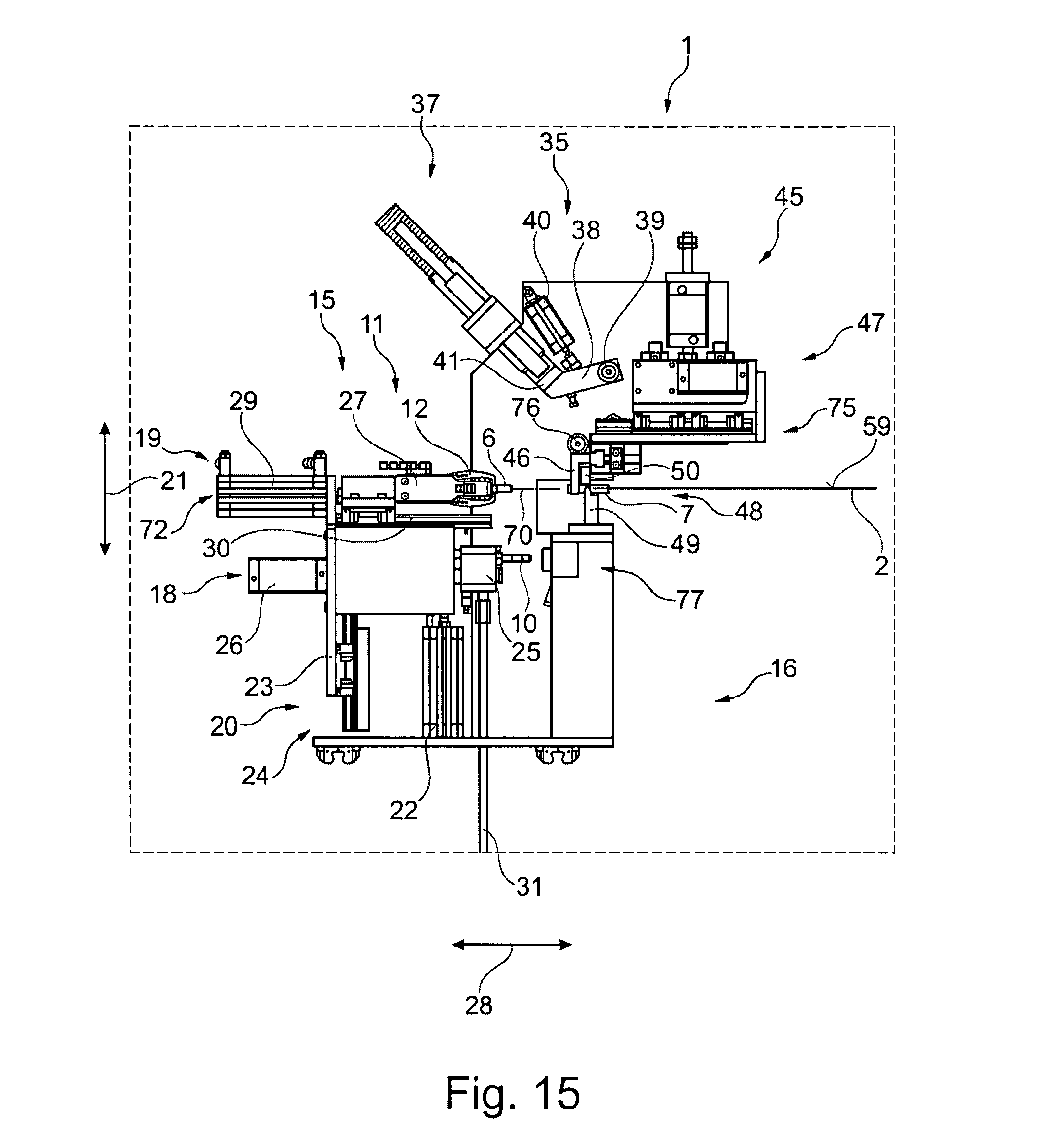
[0044] FIG. 15 schematically shows a lateral view of the assembly shown in FIGS. 1 and 2 with a plug insertion unit moved to the operating height;
[0045] FIG. 16 schematically shows a lateral view of the assembly shown in FIGS. 1 and 2 with a plug inserted in the bag, the plug still being retained by the plug insertion unit;
[0046] FIG. 17 schematically shows a lateral view of the assembly shown in FIGS. 1 and 2 with a finished bag; and
[0047] FIG. 18 schematically shows a last lateral view of the assembly shown in FIGS. 1 and 2, again in the general basic position as shown in FIG. 4;
[0048] In all figures, the horizontal bag position shown being merely a possible angular position--which can preferably be set continuously--, wherein for a different bag to be filled or for a different liquid to be filled in, a different angle could be set in all figures.
[0049] The assembly 1 shown in FIGS. 1 and 2 is used for manufacturing medical bags 2 (see FIG. 3) from a plastic film 2A, and more specifically, for filling and closing such bags 2.
[0050] For this purpose, the assembly 1 has filling means 3 for filling the bag 2 with a liquid (not shown) and closing means 4 for closing a port 5 of the bag 2 with a plug 6, which is inserted in a preferably hose-like tubular element 7 (see e. g. FIG. 3), the filling means 3 being characterized in particular by a filling nozzle 10 and the closing means 4 and being characterized in particular by a plug insertion unit 11 with a plug gripper 12.
[0051] Normally, such a port 5 of such a filled bag 2 substantially consists at least of the tubular element 7, which has been inserted in a non-releasable manner in the bag 2, and of the plug 6 fastened thereto externally or internally.
[0052] According to the invention, these filling means 3 and closing means 4 are combined in one single filling and closing station 15 so that the number of required processing stations 15, 60 and 61 in the assembly 1 is advantageously reduced.
[0053] In the state of the art, at least two separate stations (not shown here and thus without reference numeral) have always been present, wherein at the first one the bags 2 were filled and at the second one the bags 2 were subsequently closed.
[0054] These two separate stations are no longer present but have been combined to form one single combined filling and closing station 15.
[0055] The single, combined filling and closing station 15 is located at a lower frame portion 16 of an assembly frame 17 of the assembly 1 and consists substantially of a filling unit 18 and a closing unit 19 arranged above it, the filling unit 18 and the closing unit 19 forming a constructional unit (not again referenced separately) which in its entirety is fastened to the assembly frame 17 such that it is adjustable in the vertical direction 21 by a height adjusting device 20 or vertical stroke device, respectively.
[0056] Thus, the filling unit 18 and the closing unit 19 of the single combined filling and closing station 15 are translated together in the vertical direction 21 by means of a single stroke cylinder 22 of the height adjusting device 20.
[0057] The filling unit 18 and the closing unit 19 are both supported by a common carrier 23 of a common vertical support 24.
[0058] The filling unit 18 has a filling head 25 comprising the filling nozzle 10, which head can be translated horizontally by means of a first horizontal drive 26 such that the filling nozzle 10 can be translated in the horizontal direction 28 also independently to a gripping and closing head 27, comprising the plug insertion unit 11, of the closing unit 19.
[0059] The gripping and closing head 27, on the other hand, is driven in the horizontal direction 28 by means of an additional horizontal drive 29, the gripping and closing head 27 being arranged so as to be translated on a rail element 30 mounted to the filling unit 18.
[0060] Both horizontal drives 26 and 29 are fastened to the common carrier 23 of the common vertical support 24.
[0061] The filling unit 18 is provided with liquid to be filled into the bags 2 to be manufactured by a feeding line 31, whereas the plug insertion unit 11 can be equipped with additional plugs 6 by means of a regripping unit 35.
[0062] The regripping unit 35 is located in an upper frame portion 36 of the assembly frame 17 of the assembly 1 and consists substantially of a plug reservoir unit 37 for storing additional plugs 6 at the single combined filling and closing station 15, and a swivel and transfer arm 38 for gripping additional plugs 6 from the plug reservoir unit 37 and for transferring a received and gripped plug 6 to the plug insertion unit 11.
[0063] The swivel and transfer arm 38 is pivoted to the upper frame portion 36 about a swivel axis 39 and is driven by means of a working cylinder 40, and it has a plug receiving portion 41 adapted for gripping and receiving the respective plug 6.
[0064] In addition to the regripping unit 35, a bag handling unit 45 is also provided in the upper frame portion 36 of the assembly 1.
[0065] This bag handling unit 45 comprises a gripper 46 by means of which the bags 2 provided at the single combined filling and closing station 15 can be gripped at at least one of their tubular elements 7 and can be shifted with respect to the single combined filling and closing station 15.
[0066] For this purpose, the gripper 46 is mounted to the upper frame portion 36 by means of a drive unit 47 such that it can be moved both horizontally and vertically.
[0067] The bag handling unit 45 further comprises a clamping unit 48 for clamping in particular a filled bag 2 at at least one of its tubular elements 7 (see in particular FIG. 13).
[0068] The clamping unit 48 comprises a clamping element 49 displaceable in the vertical direction 21 which can be lifted or lowered with respect to a counter-clamping element 50. The clamping unit 48 also comprises a clamping drive 51.
[0069] For being able to provide the bags 2 in succession at the filling and closing station 15, the assembly 1 furthermore comprises a transport unit 55, forming a transport path 54, for transferring the bags 2 produced, below the bag handling unit 45 and laterally to the filling and closing station 15, which transport unit 55 has a circumferential belt drive 56 with seats 57 (numbered only by way of example) for receiving tubular elements 7 of bags 2, as well as an endless belt 58 for the positioning of such bags 2 (see in particular FIG. 3).
[0070] In this example of embodiment, the transport unit 55 of the assembly 1 shown in FIGS. 1 through 18 is designed such that both the filling and substantially also the closing of the bags 2 can be performed in a horizontal position at the filling and closing station 15.
[0071] To be more precise, the bags 2 are substantially located on a horizontal plane 59 (see for instance only FIG. 4) or substantially in parallel thereto, the horizontal plane 59 being illustrated directly by means of the flat bag 2 for simplicity.
[0072] By means of this transport unit 55, the bags 2 being produced are fed to additional processing stations 60 and 61 of the assembly 1.
[0073] Additional processing stations 60 and 61 can be, for instance, a receiving or feeding station 60, respectively (see only FIG. 3), where bags 2 are fed to the assembly 1, a providing station 61 (see only FIG. 17), where the filled bags 2 are provided at the assembly 1 in particular for further processing or further transport, or the like.
[0074] FIG. 3 substantially shows a portion of the receiving or feeding station 60 where bags 2 (only exemplarily shown) are sequentially transferred to the transport unit 55, either manually or if the receiving or feeding station 60 is equipped accordingly automatically.
[0075] It can easily be seen in FIG. 3 that the bag 2 with its two tubular elements 7 (only numbered by way of example) is inserted in the seats 57 (only numbered by way of example) whereas the actual plastic film 2A of the bag 2 is substantially placed on the endless belt 58.
[0076] The seats 57 shown here can also be simplified in terms of construction such that in particular an insertion of tubular elements 7 can take place automatically with particular ease and safety of operation.
[0077] The transport unit 55 is designed such that the actual belt body (not referenced again) for the belt drive 56 and the endless belt 58 at the same time serves as a guide for the bags 2.
[0078] FIG. 4 shows the assembly 1 in a general basic setting 65 of the filling unit 18, where in this general basic setting 65 one plug 6 at a time can be fed to the regripping unit 35 and picked up by the plug receiving portion 41. Feeding of the plugs can take place perhaps manually or, preferably, in an automated manner.
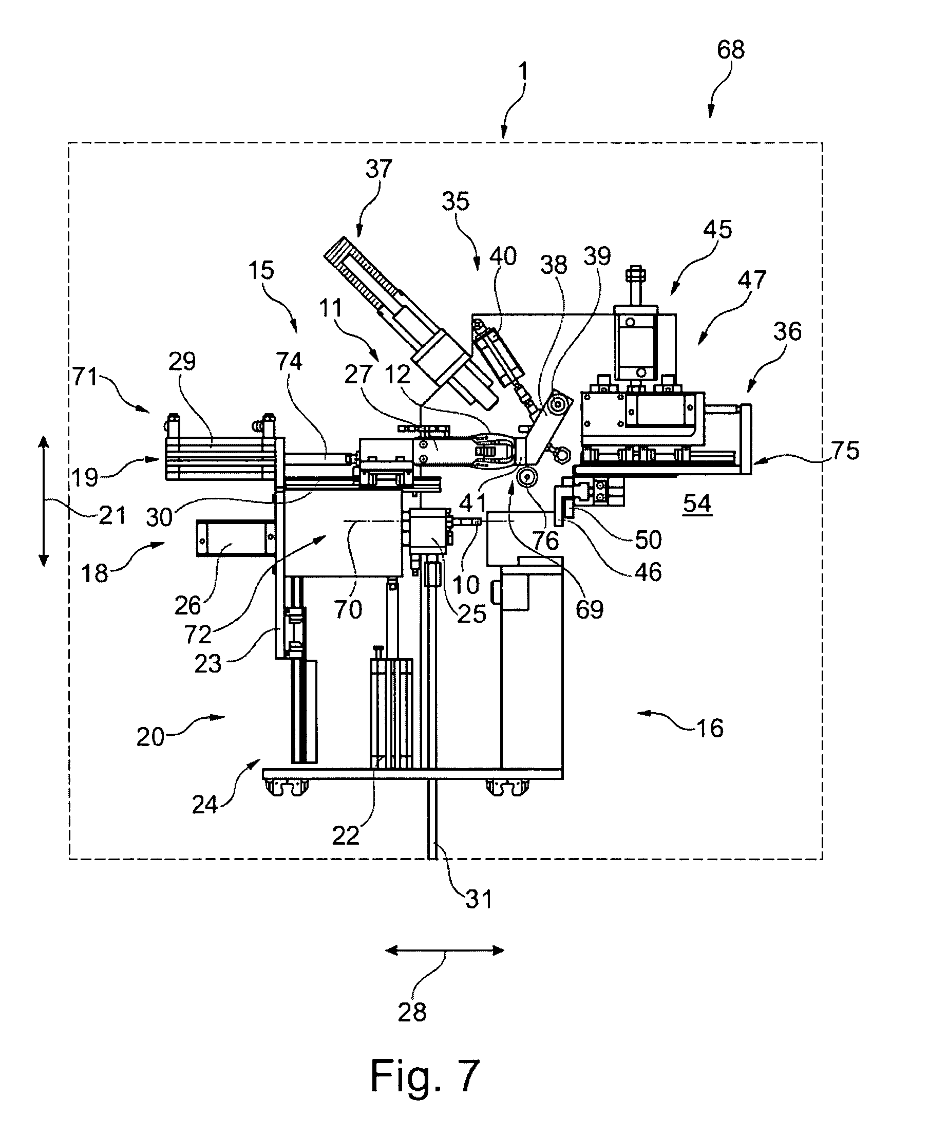
[0079] The FIGS. 5 through 8 show the assembly 1 in various plug transfer positions 68 (only numbered by way of example), wherein a bag 2 is already provided at the filling and closing station 15 by means of the transport unit 55 (not explicitly shown). The endless belt 58 of the transport unit 55 is preferably moving during this process, such that the plug 6 can be transferred from the plug reservoir unit 37 to the plug insertion unit 11 substantially in real time.
[0080] In FIG. 5, first, the swivel and transfer arm 38, provided with a plug 6 (concealed by the plug receiving portion 41) of the regripping unit 35, has already been swiveled into a transfer position 69 for this purpose, and secondly, the filling and closing station 15 has been shifted upwards by means of the height adjusting device 20. During this process, the plug receiving portion 41 of the regripping unit 35 and the plug insertion unit 11 of the gripping and closing head 27 are positioned at the same horizontal transfer height (not referenced separately), and in particular the filling nozzle 10 of the filling unit 18 is located at an operational height 70 at which the filling nozzle 10 can be adequately brought in operational contact with one of the tubular elements 7 of the bag 2.
[0081] For reaching this transfer height and in particular the operational height 70 of the filling and closing station 15, the stroke cylinder 22 of the height adjusting device 20 is moved upwards in the vertical direction 21.
[0082] If the plug insertion unit 11 is located on the horizontal level of the transfer height, the plug insertion unit 11 according to the present invention is brought to a vertical retracting position 71 with regard to the bag 2, wherein the filling nozzle 10 is positioned at the operational height 70 being located in the actual operating position 72 together with the respective bag 2.
[0083] In FIG. 6, the plug insertion unit 11 has been moved by the additional horizontal drive 29 in the direction of the plug receiving portion 41 such that the plug 6 can finally be transferred to the plug insertion unit 11 by the plug receiving portion 41. Here, a feeding cylinder 74 of the plug insertion unit 11 or of the gripping and closing head 27, respectively, is in a deployed state.
[0084] In FIG. 7, the plug 6 has been gripped by the plug gripper 12 of the plug insertion unit 11 such that the plug insertion unit 11 with the plug 6 can move back.
[0085] In FIG. 8, the cylinder 74 (see FIGS. 6 and 7) of the plug insertion unit 11 has moved back to its starting position, and correspondingly, the plug insertion unit 11 is located in the vertical retracting position 71 which has already been shown in FIG. 5.
[0086] In FIG. 9, the plug receiving portion 41 has been swiveled back in the direction of the plug reservoir unit 37 by means of the swivel and transfer arm 38.
[0087] The process of plug loading described above can overlap in time with a subsequent step of taking the bag from the seat 57, especially if the cycle time of the assembly 1 needs to be reduced.
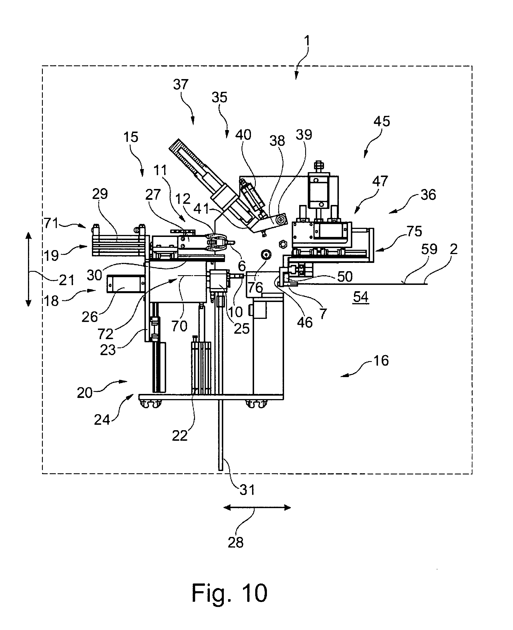
[0088] In FIG. 10, the gripper 46 of the bag handling unit 45 has already gripped the bag 2, which has arrived at the filling unit 10, by one of its tubular elements 7. The gripper 46 has been moved to this tubular element 7 by means of the drive unit 47 as soon as the respective bag 2 has arrived at the filling and closing station 15 or at its filling unit 10, respectively. Preferably, the presence of the bag 2 to be filled is detected by adapted sensors (not specifically shown).
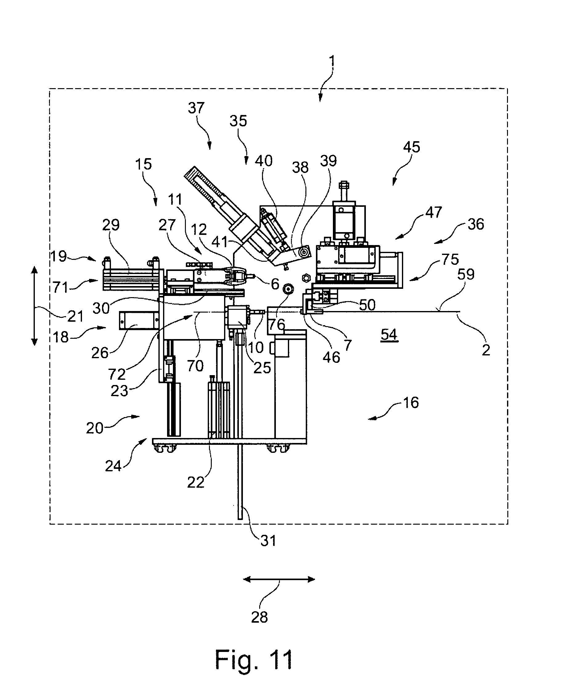
[0089] In FIG. 11, the bag 2 which has been gripped by the gripper 46 has been moved upward, such that the tubular element 7 is at least at the level of the operational height 70 of the filling nozzle 10 and the filling nozzle and the tubular element 7 are oppositely aligned, such that the filling nozzle 10 can be at least partially inserted in the tubular element 7.
[0090] In FIG. 12, the bag 2 has been moved in the horizontal direction 28 towards the filling nozzle 10 by means of a linear transport 75 of the bag handling unit 45, wherein in addition the filling head 25 is moved towards the bag 10 with or preferably without delay such that the filling nozzle 10 is inserted in the tubular element 7 of the bag 2 and the bag 2 can now be safely filled with the provided fluid.
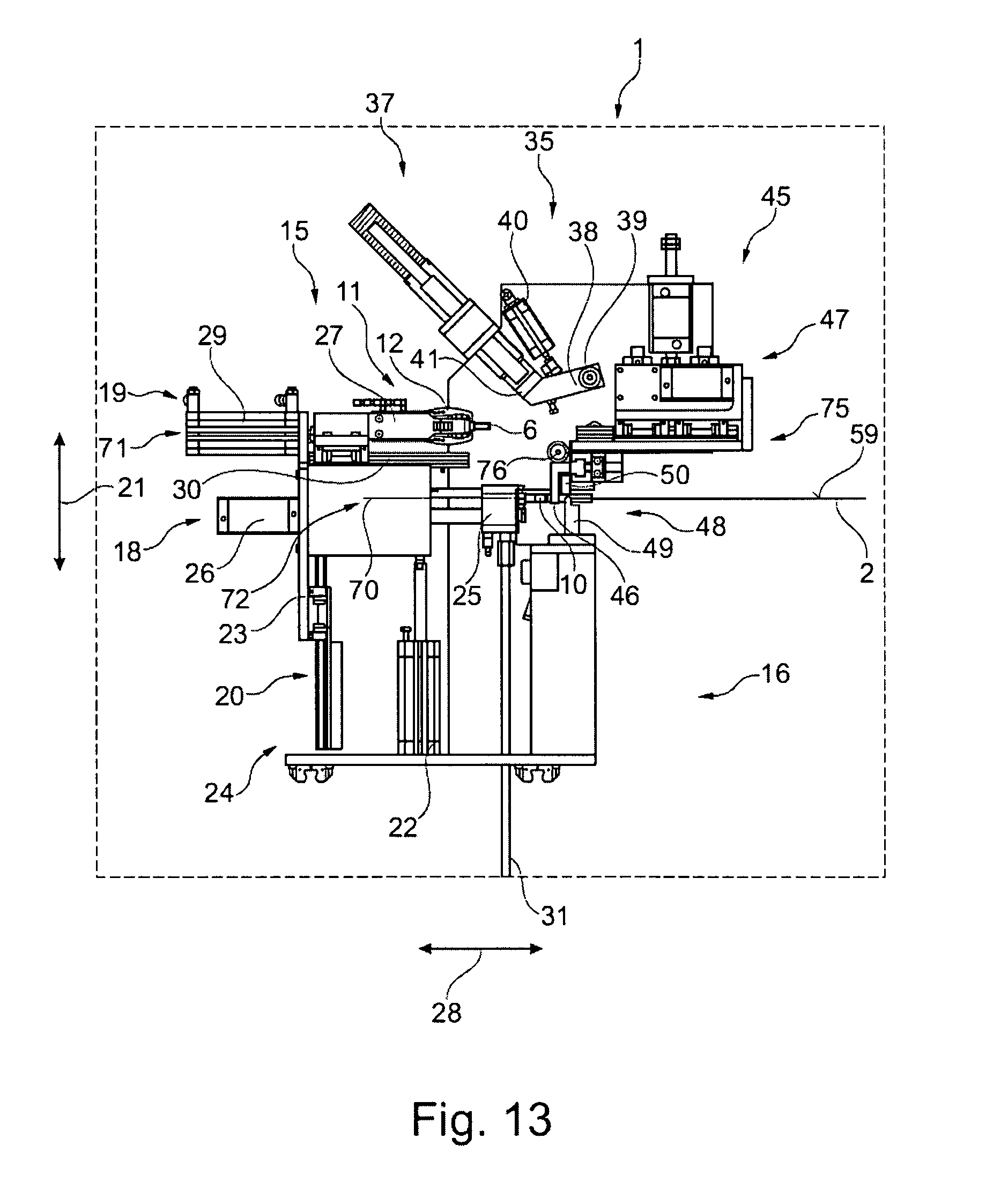
[0091] In FIG. 13, the actual filling process of the bag 2 has been completed which, however, is not shown by the way the bag 2 is drawn. Before, however, the filling nozzle 10 is removed from the tubular element 7, this tubular element 7 is clamped between the clamping element 49 of the clamping unit 48 and the counter-clamping element 50 of the clamping unit 48 so as to be tight. For this purpose, the clamping element 49 moves against the counter-clamping element 50 which corresponds to the gripper 46, the clamping forces acting on the counter-clamping element 50 acting via the gripper 46 on a deflection pulley element 76 supported in the upper frame region 36 and being transferred via this deflection pulley element 76 to the upper frame region 36 of the assembly 1.
[0092] In FIG. 14, the filling nozzle 10 has again been removed from the tubular element 7 and moved into the filling head 25 of the filling and closing station 15, with the tubular element 7 still being clamped by the clamping unit 48.
[0093] In FIG. 15, the filling and closing station 15 has again been lowered so that the plug insertion unit 11 is now positioned at the operational height 70. Thus, the plug insertion unit 11 is now located in the actual operating position 72 opposite to the bag 2 which is still in the grip of the gripper 46, the filling nozzle 10 being correspondingly now parked in an additional retracting position 77.
[0094] In FIG. 16, the plug insertion unit 11 has been moved in the horizontal direction 28 towards the bag 2 such that the plug 6 is inserted in the tubular element 7 and the closed port 5 at the bag 2 has been completed.
[0095] In FIG. 17, the plug insertion unit 11 has been moved back to its initial position in the open condition. The gripper 46 has also been opened such that the completely filled and closed bag 2 falls on the transport unit 55 and can be moved further.
[0096] In FIG. 18, the assembly 1 has returned to the general basic position 65 of the filling unit 18 that was already shown in FIG. 4. The manufacturing process can now be restarted for subsequent bags 2.
[0097] At this point, it is explicitly pointed out that the features of the solutions described above or described in the Claims and/or Figures can also be combined, if desired, so as to implement the features and achieve the effects and advantages described above in combination.
[0098] It is understood that the example of embodiment described above is merely a first embodiment of the assembly according to the invention for manufacturing a medical bag. Thus, the implementation of the invention is not limited to this example of embodiment.
[0099] All features disclosed in the application documents are claimed as essential for the invention, provided that they are novel over the state of the art individually or in combination.
LIST OF REFERENCE NUMBERS
[0100] 1 assembly [0101] 2 medical bag or subsequent bag, respectively [0102] 2A plastic film [0103] 3 filling means [0104] 4 closure means [0105] 5 port [0106] 6 plug [0107] 7 tubular element [0108] 10 filling nozzle [0109] 11 plug insertion unit [0110] 12 plug gripper [0111] 15 filling and closing station [0112] 16 lower frame portion [0113] 17 assembly frame [0114] 18 filling unit [0115] 19 closing unit [0116] 20 height adjusting device or vertical stroke device, respectively [0117] 21 vertical direction [0118] 22 stroke cylinder [0119] 23 common carrier [0120] 24 common vertical support [0121] 25 filling head [0122] 26 first horizontal drive [0123] 27 gripping and closing head [0124] 28 horizontal direction [0125] 29 additional horizontal drive [0126] 30 rail element [0127] 31 feeding line [0128] 35 regripping unit [0129] 36 upper frame region [0130] 37 plug reservoir unit [0131] 38 swivel and transfer arm [0132] 39 swivel axis [0133] 40 working cylinder [0134] 41 plug receiving portion [0135] 45 bag handling unit [0136] 46 gripper [0137] 47 drive unit [0138] 48 clamping unit [0139] 49 clamping element [0140] 50 counter-clamping element [0141] 51 clamping drive [0142] 54 transport path [0143] 55 transport unit [0144] 56 belt drive [0145] 57 seats [0146] 58 endless belt [0147] 59 horizontal plane [0148] 60 receiving or feeding station [0149] 61 providing station [0150] 65 general basic position [0151] 68 plug transfer position [0152] 69 transfer position [0153] 70 operational height [0154] 71 vertical retraction position [0155] 72 working position [0156] 74 feeding cylinder [0157] 75 linear transport [0158] 76 deflection pulley element [0159] 77 additional retraction position
* * * * *
D00000
D00001
D00002
D00003
D00004
D00005
D00006
D00007
D00008
D00009
D00010
D00011
D00012

D00013
D00014

D00015
D00016

D00017

D00018

XML
uspto.report is an independent third-party trademark research tool that is not affiliated, endorsed, or sponsored by the United States Patent and Trademark Office (USPTO) or any other governmental organization. The information provided by uspto.report is based on publicly available data at the time of writing and is intended for informational purposes only.
While we strive to provide accurate and up-to-date information, we do not guarantee the accuracy, completeness, reliability, or suitability of the information displayed on this site. The use of this site is at your own risk. Any reliance you place on such information is therefore strictly at your own risk.
All official trademark data, including owner information, should be verified by visiting the official USPTO website at www.uspto.gov. This site is not intended to replace professional legal advice and should not be used as a substitute for consulting with a legal professional who is knowledgeable about trademark law.