ECP Overlay System for Russian Distributor Valve
Skweres; Jeffrey B. ; et al.
U.S. patent application number 16/174931 was filed with the patent office on 2019-05-16 for ecp overlay system for russian distributor valve. The applicant listed for this patent is Westinghouse Air Brake Technologies Corporation. Invention is credited to Michael S. Plechey, Jeffrey B. Skweres.
| Application Number | 20190144019 16/174931 |
| Document ID | / |
| Family ID | 66431237 |
| Filed Date | 2019-05-16 |


| United States Patent Application | 20190144019 |
| Kind Code | A1 |
| Skweres; Jeffrey B. ; et al. | May 16, 2019 |
ECP Overlay System for Russian Distributor Valve
Abstract
An ECP overlay system for a Russian distributor valve includes a manifold body having a pipe bracket face configured to engage a face of a pipe bracket of a railway brake system, a valve face configured to engage a face of a main portion of a Russian distributor valve of a railway brake system, and an electric manifold face. The system further including an electric manifold assembly engaged with the electric manifold face of the manifold body, with the electric manifold assembly having a pneumatic mode where the electric manifold assembly is configured to allow pneumatic-only control of a brake cylinder of railway brake system and an ECP mode where the electric manifold assembly is configured to allow electronic control of a brake cylinder of a railway brake system.
| Inventors: | Skweres; Jeffrey B.; (McKeesport, PA) ; Plechey; Michael S.; (Jeannette, PA) | ||||||||||
| Applicant: |
|
||||||||||
|---|---|---|---|---|---|---|---|---|---|---|---|
| Family ID: | 66431237 | ||||||||||
| Appl. No.: | 16/174931 | ||||||||||
| Filed: | October 30, 2018 |
Related U.S. Patent Documents
| Application Number | Filing Date | Patent Number | ||
|---|---|---|---|---|
| 62587057 | Nov 16, 2017 | |||
| Current U.S. Class: | 303/15 |
| Current CPC Class: | B60T 17/043 20130101; B60T 15/027 20130101; B60T 17/228 20130101; B61H 13/34 20130101; B60T 13/665 20130101; B60T 15/184 20130101; B61H 13/20 20130101 |
| International Class: | B61H 13/34 20060101 B61H013/34; B60T 15/02 20060101 B60T015/02; B60T 15/18 20060101 B60T015/18; B61H 13/20 20060101 B61H013/20 |
Claims
1. An ECP overlay system for a Russian distributor valve, the system comprising: a manifold body comprising a pipe bracket face configured to engage a face of a pipe bracket of a railway brake system, a valve face configured to engage a mounting face of a main portion of a Russian distributor valve of a railway brake system, and an electric manifold face; an electric manifold assembly engaged with the electric manifold face of the manifold body, the electric manifold assembly having a pneumatic mode where the electric manifold assembly is configured to allow pneumatic-only control of a brake cylinder of railway brake system and an ECP mode where the electric manifold assembly is configured to allow electronic control of a brake cylinder of a railway brake system.
2. The system of claim 1, wherein the manifold body further comprises a plurality of ports defined by the pipe bracket face, a plurality of ports defined by the valve face, and a plurality of ports defined by the electric manifold face, the plurality of ports of the pipe bracket face are in fluid communication with the plurality of ports of the valve face via a plurality of passages extending through the manifold body, the plurality of ports of the electric manifold face are in fluid communication with the plurality of passages.
3. The system of claim 2, wherein the plurality of ports of the pipe bracket face and the plurality of ports of the valve face each comprise a reservoir pressure port, a brake pipe pressure port, a brake cylinder pressure port, a valve chamber pressure port, a working chamber pressure port, and an additional discharge channel pressure port, the reservoir pressure ports of the pipe bracket face and the valve face are in fluid communication via a reservoir pressure passage, the brake pipe pressure ports of the pipe bracket face and the valve face are in fluid communication via a brake pipe pressure passage, the brake cylinder pressure ports of the pipe bracket face and the valve face are in fluid communication via a brake cylinder pressure passage, the valve chamber pressure ports of the pipe bracket face and the valve face are in fluid communication via a valve chamber pressure passage, the working chamber pressure ports of the pipe bracket face and the valve face are in fluid communication via a working chamber pressure passage, the additional discharge channel pressure ports of the pipe bracket face and the valve face are in fluid communication via a discharge channel passage.
4. The system of claim 3, wherein a plurality of ports of the electric manifold face comprise a reservoir pressure port, a brake pipe pressure port, and a brake cylinder pressure port, the reservoir pressure port of the electric manifold face is in fluid communication with the reservoir pressure passage, the brake pipe pressure port of the electric manifold face is in fluid communication with the brake pipe pressure passage, and the brake cylinder pressure port of the electric manifold face is in fluid communication with the brake cylinder pressure passage.
5. The system of claim 1, wherein the electric manifold assembly comprises a cut-out valve, a fill valve, and a brake cylinder exhaust valve, the cut-out valve, the fill valve, and the brake cylinder exhaust valve each having an open position and closed position, and wherein, when the electric manifold assembly is in the ECP mode with the fill valve in the open position and the cut-out valve and the brake cylinder exhaust valve each in the closed position, the fill valve is configured to place a reservoir pressure passage in fluid communication with a brake cylinder pressure passage.
6. The system of claim 5, wherein the fill valve is configured to place a reservoir pressure passage in fluid communication with a brake cylinder pressure passage via a brake cylinder fill choke.
7. The system of claim 5, wherein, when the electric manifold assembly is in the ECP mode with the brake cylinder exhaust valve in the open position and the fill valve in the closed position, the brake cylinder exhaust valve is configured to place a brake cylinder pressure passage in fluid communication with atmospheric pressure.
8. The system of claim 7, wherein the brake cylinder exhaust valve is configured to place a brake cylinder pressure passage in fluid communication with atmospheric pressure via a brake cylinder exhaust choke.
9. The system of claim 5, wherein the cut-out valve, the fill valve, and the brake cylinder exhaust valve are electronically-controlled via a cut-out solenoid, a fill solenoid, and a brake cylinder exhaust solenoid, respectively.
10. The system of claim 9, wherein the cut-out valve, the fill valve, and the brake cylinder exhaust valve each comprise a diaphragm check valve, the cut-out valve biased to the open position, the fill valve biased to the closed position, the brake cylinder exhaust valve biased to the open position, the cut-out solenoid, the fill solenoid, and the brake cylinder exhaust solenoid each configured to supply pneumatic pressure to the respective cut-out valve, the fill valve, and the brake cylinder exhaust valve to maintain the cut-out valve, the fill valve, and the brake cylinder exhaust valve in the closed position.
11. The system of claim 5, wherein, when the electric manifold assembly is in the pneumatic mode, the cut-out valve is in the open position to place a brake cylinder passage in fluid communication with a brake cylinder port of the valve face of the manifold body, the fill valve is in the closed position, and the brake cylinder exhaust valve is in the closed position.
12. The system of claim 5, wherein the electric manifold assembly further comprises a reservoir pressure transducer, a brake pipe pressure transducer, and a brake cylinder pressure transducer.
13. The system of claim 1, wherein the manifold body is configured to be positioned between a pipe bracket and a main portion of Russian distributor valve.
14. The system of claim 4, wherein the electric manifold assembly comprises a cut-out valve, a fill valve, and a brake cylinder exhaust valve, the cut-out valve, the fill valve, and the brake cylinder exhaust valve each having an open position and closed position, and wherein, when the electric manifold assembly is in the ECP mode with the fill valve in the open position and the cut-out valve and the brake cylinder exhaust valve each in the closed position, the fill valve is configured to place the reservoir pressure passage in fluid communication with the brake cylinder pressure passage.
15. The system of claim 14, wherein the fill valve is configured to place the reservoir pressure passage in fluid communication with the brake cylinder pressure passage via a brake cylinder fill choke.
16. The system of claim 14, wherein, when the electric manifold assembly is in the ECP mode with the brake cylinder exhaust valve in the open position and the fill valve in the closed position, the brake cylinder exhaust valve is configured to place the brake cylinder pressure passage in fluid communication with atmospheric pressure.
17. The system of claim 16, wherein the brake cylinder exhaust valve is configured to place the brake cylinder pressure passage in fluid communication with atmospheric pressure via a brake cylinder exhaust choke.
18. The system of claim 14, wherein the cut-out valve, the fill valve, and the brake cylinder exhaust valve are electronically-controlled via a cut-out solenoid, a fill solenoid, and a brake cylinder exhaust solenoid, respectively.
19. The system of claim 18, wherein the cut-out valve, the fill valve, and the brake cylinder exhaust valve each comprise a diaphragm check valve, the cut-out valve biased to the open position, the fill valve biased to the closed position, the brake cylinder exhaust valve biased to the open position, the cut-out solenoid, the fill solenoid, and the brake cylinder exhaust solenoid each in fluid communication with the reservoir pressure passage and configured to supply air from the reservoir pressure passage to the respective cut-out valve, the fill valve, and the brake cylinder exhaust valve to maintain the cut-out valve, the fill valve, and the brake cylinder exhaust valve in the closed position.
20. The system of claim 14, wherein, when the electric manifold assembly is in the pneumatic mode, the cut-out valve is in the open position to place the brake cylinder pressure passage in fluid communication with a main portion of a Russian distributor valve, the fill valve is in the closed position, and the brake cylinder exhaust valve is in the closed position.
Description
CROSS-REFERENCE TO RELATED APPLICATION
[0001] This application claims priority to U.S. Provisional Application Ser. No. 62/587,057, filed Nov. 16, 2017, which is hereby incorporated by reference in its entirety.
BACKGROUND OF THE INVENTION
Field of the Invention
[0002] The present invention relates to a brake apparatus for railway vehicles and, more particularly, to an ECP overlay system for a Russian distributor valve.
Description of Related Art
[0003] Railroad freight cars have a brake pipe that runs through each car and is coupled therebetween so as to extend continuously the length of the train. The brake pipe is charged with compressed air typically at the head end by a compressor on the locomotive. The compressed air not only provides the pneumatic brake force at the respective cars, but also serves as a communication link in which the car's brakes are controlled from the locomotive by increasing and decreasing the brake pipe pressure. Brake equipment for railroad freight cars utilizes control valves, also known as distributor valves, to control the operation of the brake cylinders and brakes for the freight cars.
[0004] Russian distributor valve systems operate similarly to American Association of Railroads (AAR) pneumatic air brake valves (such as the WABCO ABDX control valve), with a pipe bracket portion, main-line portion, a main portion, a reservoir, and a brake cylinder.
[0005] Brake equipment may include Electronically Controlled Pneumatic (ECP) systems to allow for the electronic control of the brakes rather than pneumatic control. ECP braking systems offer many advantages over pneumatic-only control, including superior braking and safety capabilities. ECP brake equipment on each rail vehicle may include a stand-alone All Electric Manifold (AEM), which contains pressure transducers, various pneumatic and electro-pneumatic valves, etc. This equipment is used to monitor the pressures in the brake pipe, the brake cylinder(s), and specific reservoirs, and to convert the electrical brake commands into a form usable by a microprocessor. Operating according to its programming code and to the dictation of the brake commands and other electrical signals it has received, the microprocessor controls the electro-pneumatic valves.
SUMMARY OF THE INVENTION
[0006] In one aspect, an ECP overlay system for a Russian distributor valve, the system comprising a manifold body comprising a pipe bracket face configured to engage a face of a pipe bracket of a railway brake system, a valve face configured to engage a mounting face of a main portion of a Russian distributor valve of a railway brake system, and an electric manifold face, an electric manifold assembly engaged with the electric manifold face of the manifold body, the electric manifold assembly having a pneumatic mode where the electric manifold assembly is configured to allow pneumatic-only control of a brake cylinder of railway brake system and an ECP mode where the electric manifold assembly is configured to allow electronic control of a brake cylinder of a railway brake system.
[0007] The manifold body may further include a plurality of ports defined by the pipe bracket face, a plurality of ports defined by the valve face, and a plurality of ports defined by the electric manifold face, the plurality of ports of the pipe bracket face are in fluid communication with the plurality of ports of the valve face via a plurality of passages extending through the manifold body, the plurality of ports of the electric manifold face are in fluid communication with the plurality of passages.
[0008] The plurality of ports of the pipe bracket face and the plurality of ports of the valve face may each include a reservoir pressure port, a brake pipe pressure port, a brake cylinder pressure port, a valve chamber pressure port, a working chamber pressure port, and an additional discharge channel pressure port, where the reservoir pressure ports of the pipe bracket face and the valve face are in fluid communication via a reservoir pressure passage, the brake pipe pressure ports of the pipe bracket face and the valve face are in fluid communication via a brake pipe pressure passage, the brake cylinder pressure ports of the pipe bracket face and the valve face are in fluid communication via a brake cylinder pressure passage, the valve chamber pressure ports of the pipe bracket face and the valve face are in fluid communication via a valve chamber pressure passage, the working chamber pressure ports of the pipe bracket face and the valve face are in fluid communication via a working chamber pressure passage, and the additional discharge channel pressure ports of the pipe bracket face and the valve face are in fluid communication via a discharge channel passage.
[0009] A plurality of ports of the electric manifold face may include a reservoir pressure port, a brake pipe pressure port, and a brake cylinder pressure port, the reservoir pressure port of the electric manifold face is in fluid communication with the reservoir pressure passage, the brake pipe pressure port of the electric manifold face is in fluid communication with the brake pipe pressure passage, and the brake cylinder pressure port of the electric manifold face is in fluid communication with the brake cylinder pressure passage.
[0010] The electric manifold assembly may include a cut-out valve, a fill valve, and a brake cylinder exhaust valve, the cut-out valve, the fill valve, and the brake cylinder exhaust valve each having an open position and closed position, and wherein, when the electric manifold assembly is in the ECP mode with the fill valve in the open position and the cut-out valve and the brake cylinder exhaust valve each in the closed position, the fill valve is configured to place a reservoir pressure passage in fluid communication with a brake cylinder pressure passage.
[0011] The fill valve may be configured to place a reservoir pressure passage in fluid communication with a brake cylinder pressure passage via a brake cylinder fill choke.
[0012] When the electric manifold assembly is in the ECP mode with the brake cylinder exhaust valve in the open position and the fill valve in the closed position, the brake cylinder exhaust valve may be configured to place a brake cylinder pressure passage in fluid communication with atmospheric pressure.
[0013] The brake cylinder exhaust valve may be configured to place a brake cylinder pressure passage in fluid communication with atmospheric pressure via a brake cylinder exhaust choke.
[0014] The cut-out valve, the fill valve, and the brake cylinder exhaust valve may be electronically-controlled via a cut-out solenoid, a fill solenoid, and a brake cylinder exhaust solenoid, respectively.
[0015] The cut-out valve, the fill valve, and the brake cylinder exhaust valve may each include a diaphragm check valve, with the cut-out valve biased to the open position, the fill valve biased to the closed position, the brake cylinder exhaust valve biased to the open position. The cut-out solenoid, the fill solenoid, and the brake cylinder exhaust solenoid each configured to supply pneumatic pressure to the respective cut-out valve, the fill valve, and the brake cylinder exhaust valve to maintain the cut-out valve, the fill valve, and the brake cylinder exhaust valve in the closed position.
[0016] When the electric manifold assembly is in the pneumatic mode, the cut-out valve is in the open position to place a brake cylinder passage in fluid communication with a brake cylinder port of the valve face of the manifold body, the fill valve is in the closed position, and the brake cylinder exhaust valve is in the closed position.
[0017] The electric manifold assembly may further include a reservoir pressure transducer, a brake pipe pressure transducer, and a brake cylinder pressure transducer.
[0018] The manifold body may be configured to be positioned between a pipe bracket and a main portion of a Russian distributor valve.
[0019] The electric manifold assembly may include a cut-out valve, a fill valve, and a brake cylinder exhaust valve, with the cut-out valve, the fill valve, and the brake cylinder exhaust valve each having an open position and closed position, and where, when the electric manifold assembly is in the ECP mode with the fill valve in the open position and the cut-out valve and the brake cylinder exhaust valve each in the closed position, the fill valve is configured to place the reservoir pressure passage in fluid communication with the brake cylinder pressure passage.
[0020] The fill valve may be configured to place the reservoir pressure passage in fluid communication with the brake cylinder pressure passage via a brake cylinder fill choke.
[0021] When the electric manifold assembly is in the ECP mode with the brake cylinder exhaust valve in the open position and the fill valve in the closed position, the brake cylinder exhaust valve may be configured to place the brake cylinder pressure passage in fluid communication with atmospheric pressure.
[0022] The brake cylinder exhaust valve may be configured to place the brake cylinder pressure passage in fluid communication with atmospheric pressure via a brake cylinder exhaust choke.
[0023] The cut-out valve, the fill valve, and the brake cylinder exhaust valve may be electronically-controlled via a cut-out solenoid, a fill solenoid, and a brake cylinder exhaust solenoid, respectively.
[0024] The cut-out valve, the fill valve, and the brake cylinder exhaust valve may each include a diaphragm check valve, with the cut-out valve biased to the open position, the fill valve biased to the closed position, the brake cylinder exhaust valve biased to the open position. The cut-out solenoid, the fill solenoid, and the brake cylinder exhaust solenoid each in fluid communication with the reservoir pressure passage and configured to supply air from the reservoir pressure passage to the respective cut-out valve, the fill valve, and the brake cylinder exhaust valve to maintain the cut-out valve, the fill valve, and the brake cylinder exhaust valve in the closed position.
[0025] When the electric manifold assembly is in the pneumatic mode, the cut-out valve is in the open position to place the brake cylinder pressure passage in fluid communication with a main portion of a Russian distributor valve, the fill valve is in the closed position, and the brake cylinder exhaust valve is in the closed position.
[0026] Further details and advantages of the various embodiments of the invention detailed herein will become clear upon reviewing the following detailed description of the preferred embodiments in conjunction with the accompanying drawing figures.
BRIEF DESCRIPTION OF THE DRAWINGS
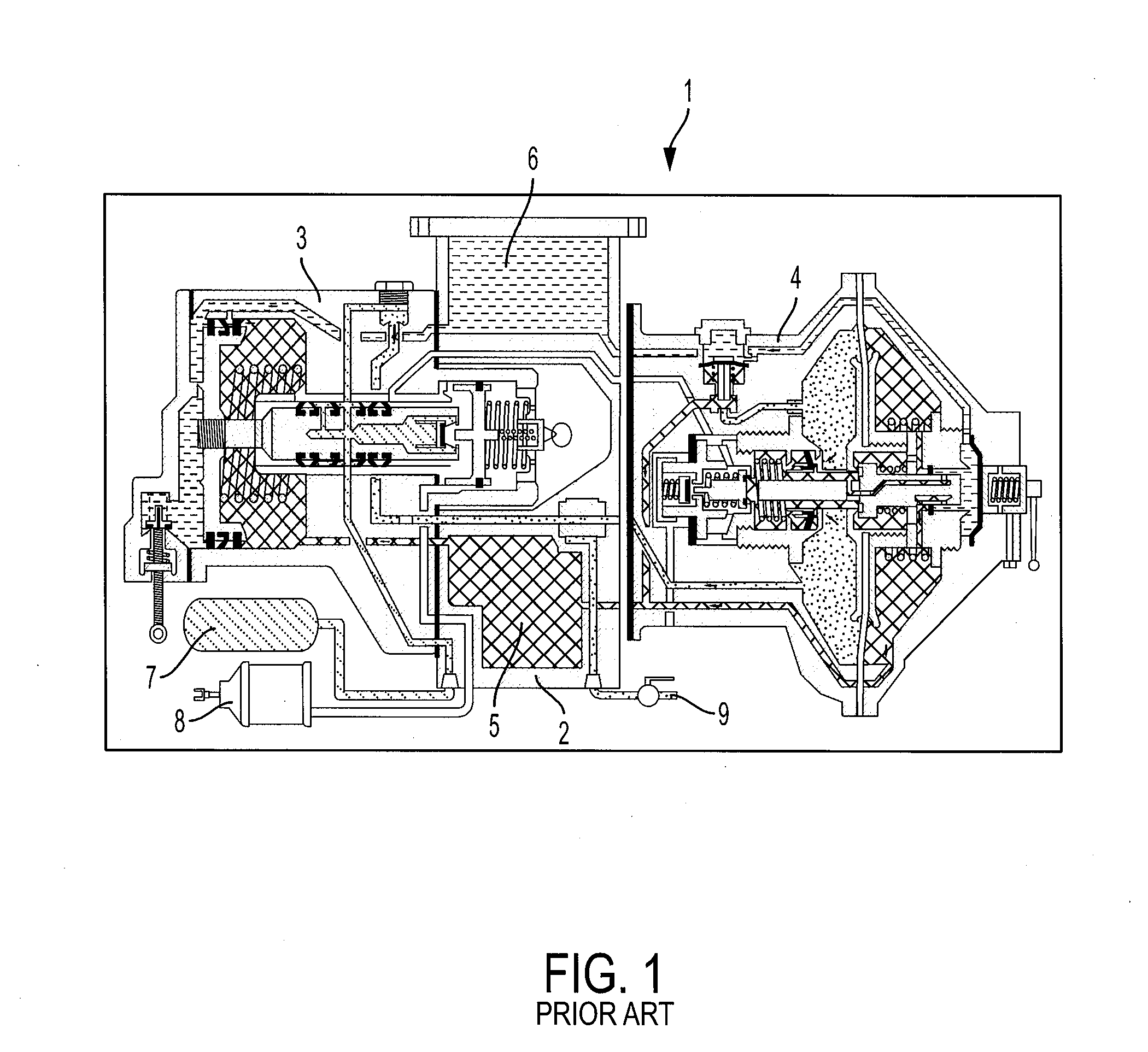
[0027] FIG. 1 is a cross-sectional view of a Russian distributor valve.
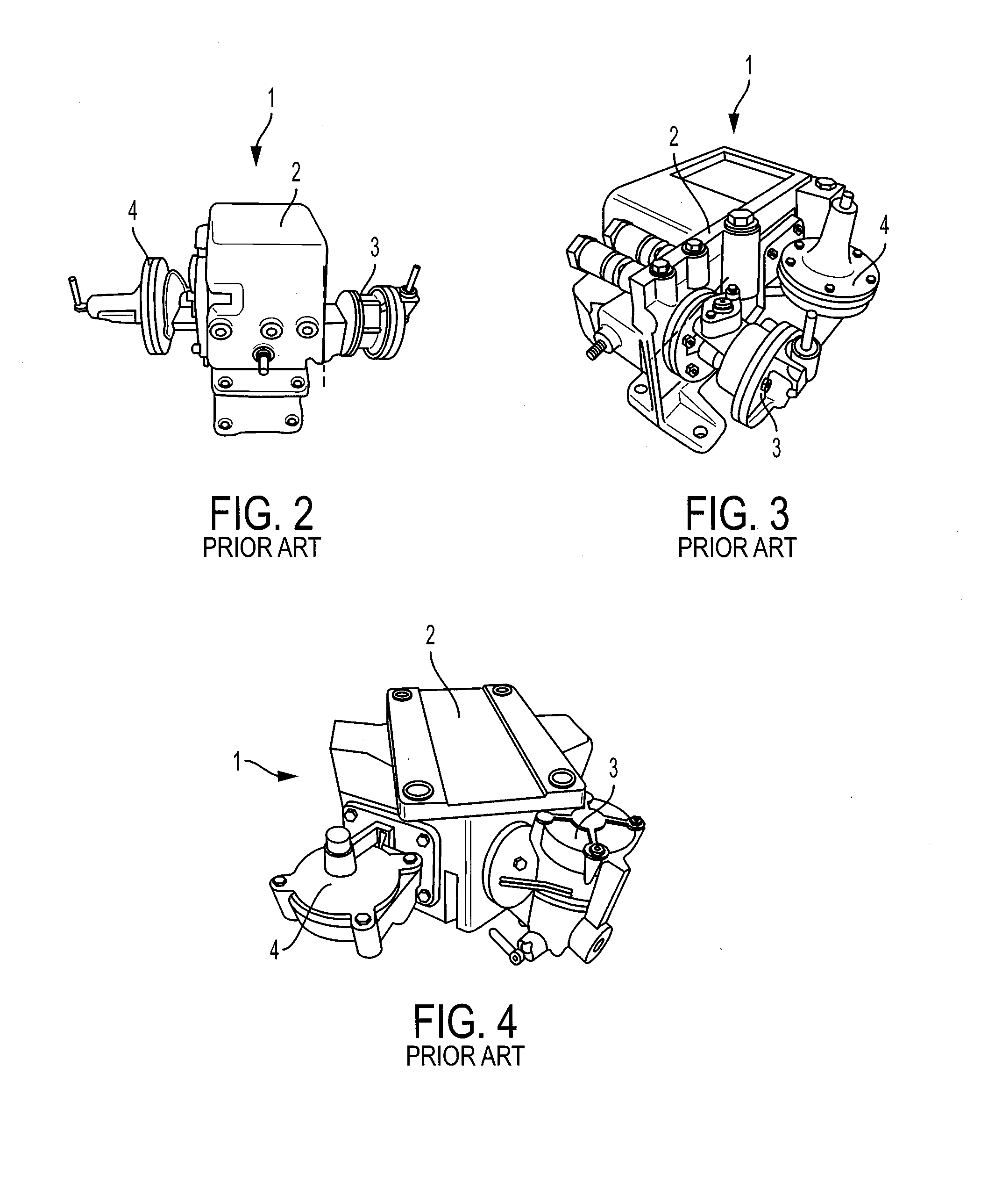
[0028] FIG. 2 is a perspective view of a Russian distributor valve according to one configuration.
[0029] FIG. 3 is a perspective view of a Russian distributor valve according to a further configuration.
[0030] FIG. 4 is a perspective view of a Russian distributor valve according to another configuration.
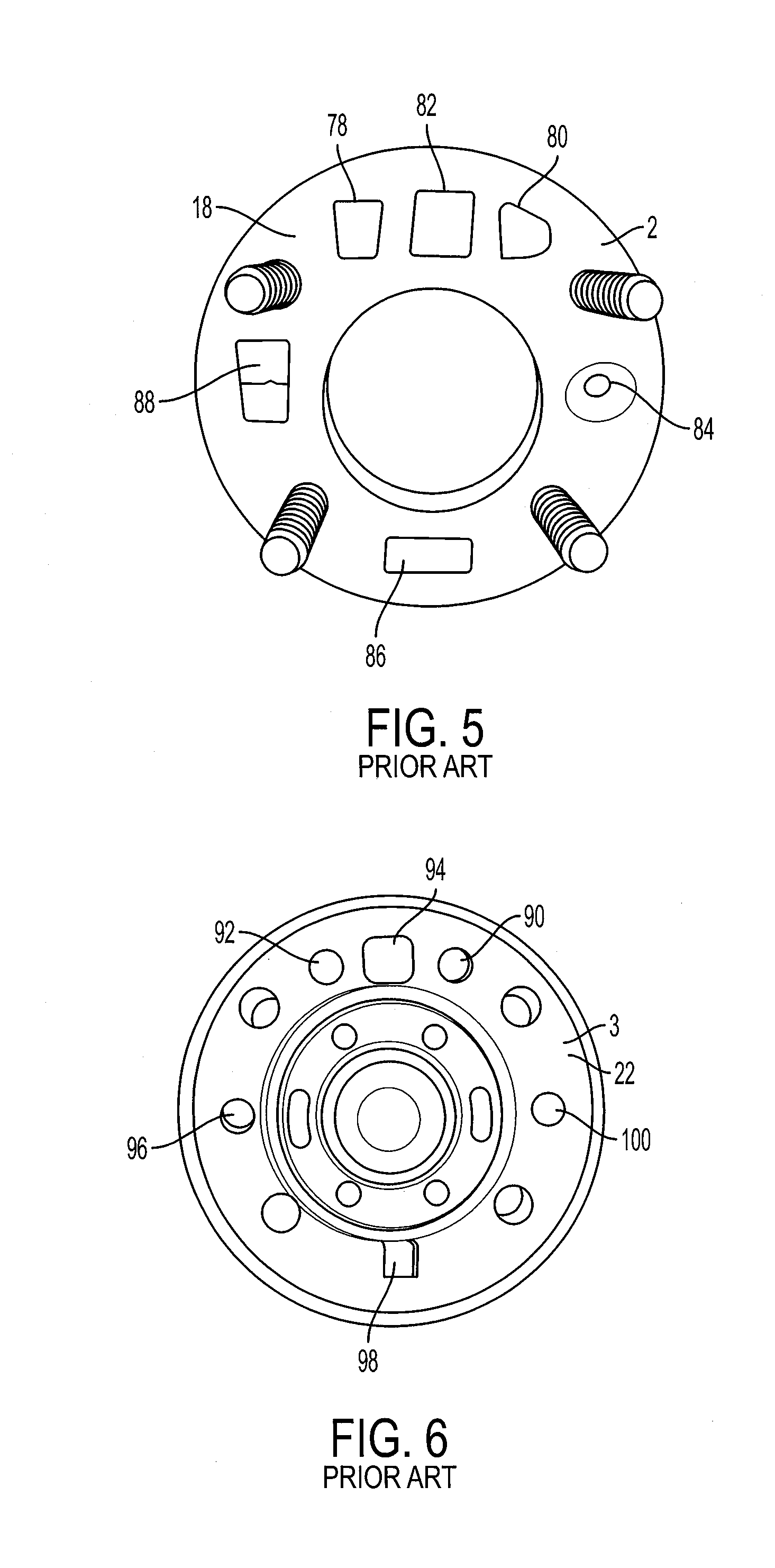
[0031] FIG. 5 a front view of a main portion mounting face of a pipe bracket of the braking system of FIG. 1.
[0032] FIG. 6 is a front view of a mounting face of a main portion of the distributor valve of FIG. 1.
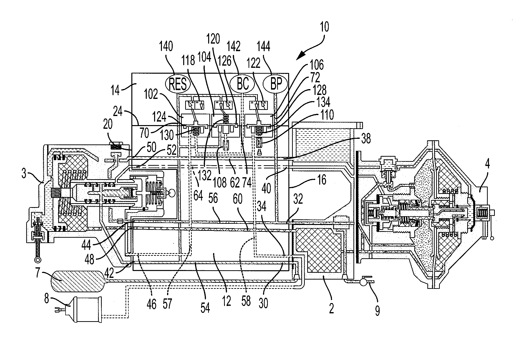
[0033] FIG. 7 is a schematic view of an ECP overlay system according to one aspect of the present invention, showing the system in a pneumatic mode (ECP in cut-out position) with a distributor valve in a release position.
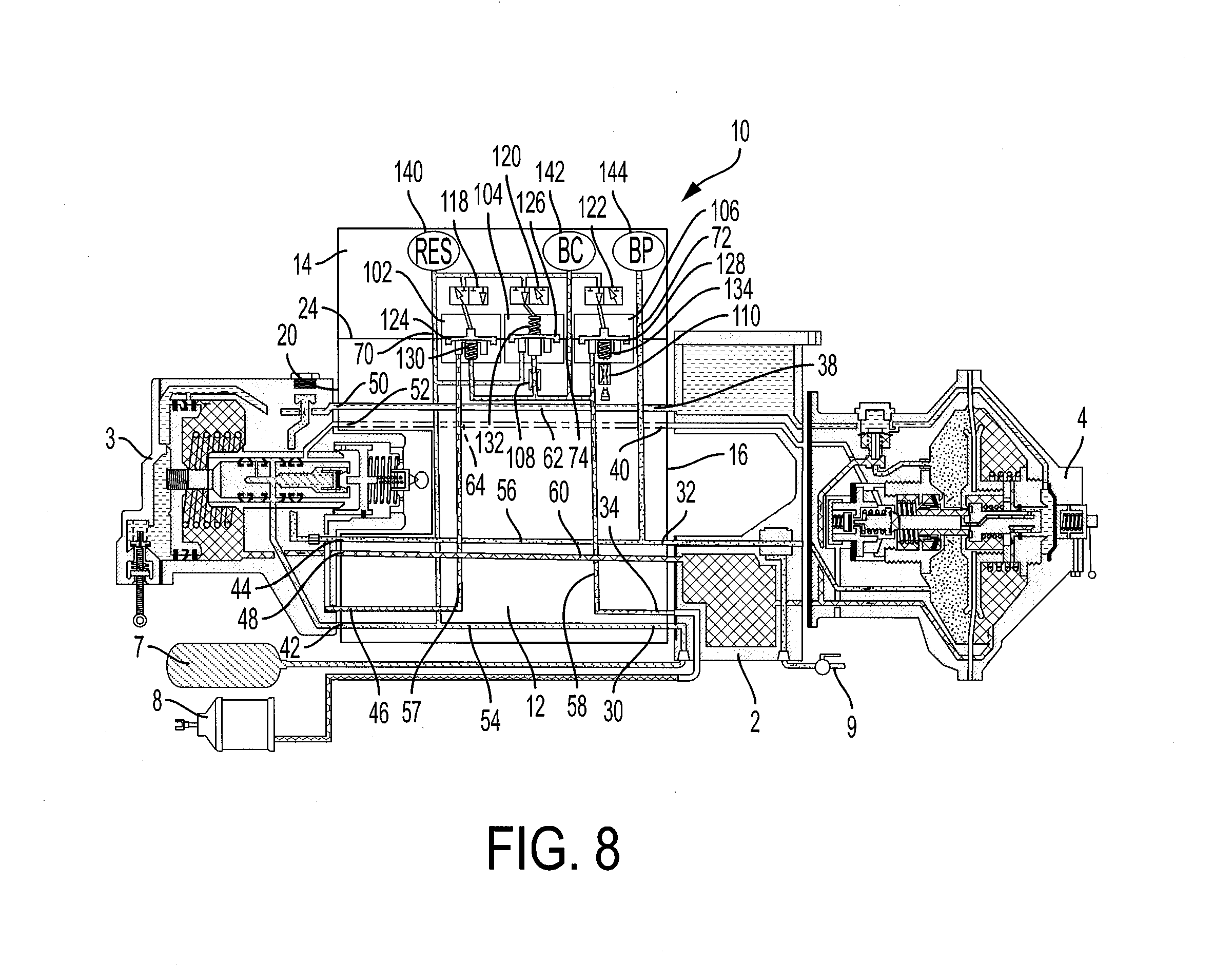
[0034] FIG. 8 is a schematic view of the ECP overlay system of FIG. 7 showing the system in a pneumatic mode (ECP in cut-out position) with a distributor valve in an applied position.
[0035] FIG. 9 is a schematic view of the ECP overlay system of FIG. 7, showing the system in an ECP cut-in position with the brakes released.
[0036] FIG. 10 is a schematic view of the ECP overlay system of FIG. 7, showing the system in an ECP cut-in position with the brakes in an applied position.
[0037] FIG. 11 is a schematic view of the ECP overlay system of FIG. 7, showing the system in an ECP cut-in position with the brakes being released position.
DETAILED DESCRIPTION
[0038] For purposes of the description hereinafter, spatial orientation terms, as used, shall relate to the referenced embodiment as it is oriented in the accompanying drawing figures or otherwise described in the following detailed description. However, it is to be understood that the embodiments described hereinafter may assume many alternative variations and configurations. It is also to be understood that the specific components, devices, and features illustrated in the accompanying drawing figures and described herein are simply exemplary and should not be considered as limiting.
[0039] Referring to FIGS. 1-6, a Russian distributor valve 1 includes a pipe bracket 2 having various pipes attached thereto for establishing a pneumatic connection between the various components of the Russian Distributor valve 1. A main portion 3 and main-line portion 4 are secured to the pipe bracket 2. As shown in FIGS. 2-4, the pipe bracket 2, main portion 3, and main-line portion 4 of the Russian Distributor valve 1 may have various configurations and orientations. The pipe bracket 2 contains an internal valve chamber 5 and an internal working chamber 6 and is in fluid communication with a reservoir 7, a brake cylinder 8, and a brake pipe 9. The flow of the pressurized air between various locations within the Russian Distributor valve 1 is controlled by the main portion 3 and the main-line portion 4 to perform various brake valve functions, including application and release of the brake cylinder 8.
[0040] Referring to FIGS. 7-11, an ECP overlay system 10 for a Russian distributor valve 1 is shown. Although specific configurations of the Russian distributor valve 1 are shown in FIGS. 1-11, the ECP overlay system 10 may be utilized in connection with various configurations of Russian distributor valves. The ECP overlay system 10 includes a manifold body 12 and an electric manifold assembly 14 as discussed in more detail below.
[0041] Referring to FIGS. 1-11, the manifold body 12 is configured to be positioned between the pipe bracket 2 and the main portion 3 of the Russian distributor valve 1. The manifold body 12 includes a pipe bracket face 16 configured to engage a main portion mounting face 18 of the pipe bracket 2 of the Russian distributor valve 1, a valve face 20 configured to engage a mounting face 22 of the main portion 3 of a Russian distributor valve 1 of a railway brake system, and an electric manifold face 24 configured to engage the electric manifold assembly 14. The pipe bracket face 16 defines a reservoir pressure port 30, a brake pipe pressure port 32, a brake cylinder pressure port 34, a valve chamber pressure port 36, a working chamber pressure port 38, and an additional discharge channel pressure port 40. The valve face 20 also defines a reservoir pressure port 42, a brake pipe pressure port 44, a brake cylinder pressure port 46, a valve chamber pressure port 48, a working chamber pressure port 50, and an additional discharge channel pressure port 52. The reservoir pressure ports 30, 42 of the pipe bracket face 16 and the valve face 20 are in fluid communication via a reservoir pressure passage 54. The brake pipe pressure ports 32, 44 of the pipe bracket face 16 and the valve face 20 are in fluid communication via a brake pipe pressure passage 56. The brake cylinder pressure ports 34, 46 of the pipe bracket face 16 and the valve face 20 are in fluid communication via a brake cylinder pressure passages 57, 58. The valve chamber pressure ports 36, 48 of the pipe bracket face 16 and the valve face 20 are in fluid communication via a valve chamber pressure passage 60. The working chamber pressure ports 38, 50 of the pipe bracket face 16 and the valve face 20 are in fluid communication via a working chamber pressure passage 62. The additional discharge channel pressure ports 40, 52 of the pipe bracket face 16 and the valve face 20 are in fluid communication via a discharge channel passage 64.
[0042] Referring to FIGS. 7-11, the electric manifold face 24 also includes a reservoir pressure port 70, a brake pipe pressure port 72, and a brake cylinder pressure port 74. The reservoir pressure port 70 of the electric manifold face 24 is in fluid communication with the reservoir pressure passage 54, the brake pipe pressure port 72 of the electric manifold face 24 is in fluid communication with the brake pipe pressure passage 56, and the brake cylinder pressure port 74 of the electric manifold face 24 is in fluid communication with the brake cylinder pressure passage 58. The manifold body 12 may include a plurality of mounting openings (not shown) configured to receive mounting studs (not shown) from the main portion mounting face 18 of the pipe bracket 2 for securing the manifold body 12 and the main portion 3 of the Russian distributor valve 1 to the pipe bracket 2. The mounting studs may extend through the manifold body 12 and further through a flange of the main portion 3 of the Russian distributor valve 1 for securing the manifold body 12 and the main portion 3 to the pipe bracket 2. The mounting studs of the pipe bracket 2 may be modified or replaced with longer studs to accommodate the manifold body 12.
[0043] Referring to FIGS. 5 and 6, the main portion mounting face 18 of the pipe bracket 2 of the Russian distributor valve 1 includes a reservoir pressure port 78, a brake pipe pressure port 80, a brake cylinder pressure port 82, a valve chamber pressure port 84, a working chamber pressure port 86, and an additional discharge channel pressure port 88 that are configured to be aligned with the corresponding ports 30, 32, 34, 36, 38, 40 of the pipe bracket face 16 of the manifold body 12 discussed above. The mounting face 22 of the main portion 3 of the Russian distributor valve 1 also includes a reservoir pressure port 90, a brake pipe pressure port 92, a brake cylinder pressure port 94, a valve chamber pressure port 96, a working chamber pressure port 98, and an additional discharge channel pressure port 100 that are that are configured to be aligned with the corresponding ports 42, 44, 46, 48, 50, 52 of the valve face 20 of the manifold body 12 discussed above. Accordingly, the manifold body 12 allows for the fluid communication between the pipe bracket 2 and the main portion 3 of the Russian distributor valve 1 while providing access to the various pressures of the system via the electric manifold face 24 for ECP functionality.
[0044] Referring to FIGS. 7-11, the electric manifold assembly 14 is engaged with the electric manifold face 24 of the manifold body 12. The electric manifold assembly 14 may include a coin plate (not shown) secured to the manifold body 12. The electric manifold assembly 14 has a pneumatic mode (ECP cut-out) where the electric manifold assembly 14 is configured to allow pneumatic-only control of the brake cylinder 8 of railway brake system and an ECP mode (ECP cut-in) where the electric manifold assembly 14 is configured to allow electronic control of the brake cylinder 8 of a railway brake system. When the electric manifold assembly 14 is in the pneumatic mode, the electric manifold assembly 14 allows the freight brake control valve portion to have control of the railway brake system. When the electric manifold assembly 14 is in ECP mode, the electric manifold assembly 14 allows electronic control to either fill and/or exhaust brake cylinder 8 of a railway brake system.
[0045] Referring again to FIGS. 7-11, the electric manifold assembly 14 includes a cut-out valve 102, a fill valve 104, and a brake cylinder exhaust valve 106. The cut-out valve 102, the fill valve 104, and the brake cylinder exhaust valve 106 each have an open position and closed position. When the electric manifold assembly 14 is in the ECP mode (ECP cut-in and in "brake application mode) with the fill valve 104 in the open position and the cut-out valve 102 and the brake cylinder exhaust valve 106 each in the closed position, as shown in FIG. 10, the fill valve 104 is configured to place the reservoir passage 54 in fluid communication with the brake cylinder pressure passage 58. As discussed in more detail below, the ECP overlay system 10 shown in FIG. 10 is in ECP mode during a brake application. The fill valve 104 is configured to place the reservoir passage 54 in fluid communication with the brake cylinder pressure 58 passage via a brake cylinder fill choke 108. The cut-out valve 102 is configured to isolate brake cylinder pressure passage 57 from the brake cylinder passage 58. When the electric manifold assembly 14 is in the ECP mode (ECP cut-in and in "brake release mode") with the brake cylinder exhaust valve 106 in the open position and the fill valve 104 in the closed position, as shown in FIG. 11, the brake cylinder exhaust valve 106 is configured to place the brake cylinder pressure passage 58 in fluid communication with atmospheric pressure. In particular, the brake cylinder exhaust valve 106 is configured to place the brake cylinder pressure passage 58 in fluid communication with atmospheric pressure via a brake cylinder exhaust choke 110. The cut-out valve 102 is in the open position thus allowing fluid communication with the brake cylinder pressure passages 57, 58. When the electric manifold assembly 14 is in the pneumatic mode (ECP cut-out), as shown in FIGS. 7 and 8, the cut-out valve 102 is in the open position to place both brake cylinder passages 57, 58 and brake cylinder 8 in fluid communication with the main portion 3 of the Russian distributor valve 1 via the brake cylinder port 46 of the valve face 20 of the manifold body 12, the fill valve 104 is in the closed position, and the brake cylinder exhaust valve 106 is in the closed position. The cut-out valve 102 is configured to place the brake cylinder passages 57, 58 in fluid communication with the main portion 3 of the Russian distributor valve 1 thereby allowing the main portion 3 to be pneumatically responsible for applying and releasing the brake cylinder 8.
[0046] The cut-out valve 102, the fill valve 104, and the brake cylinder exhaust valve 106 are electronically-controlled via a cut-out solenoid 118, a fill solenoid 120, and a brake cylinder exhaust solenoid 122, respectively. The cut-out valve 102, the fill valve 104, and the brake cylinder exhaust valve 106 are each diaphragm check valves having a diaphragm 124, 126, 128, although other suitable valve arrangements may be utilized. The cut-out valve 102 is biased to the open position, the fill valve 104 is biased to the closed position, and the brake cylinder exhaust valve 106 is biased to the open position. The cut-out valve 102, the fill valve 104, and the brake cylinder exhaust valve 106 may be biased to their respective position via respective springs 130, 132, 134, although other suitable arrangements may be utilized. The cut-out solenoid 118, the fill solenoid 120, and the brake cylinder exhaust solenoid 122 are each configured to supply pneumatic pressure to the respective cut-out valve 102, the fill valve 104, and the brake cylinder exhaust valve 106 to maintain the cut-out valve 102, the fill valve 104, and the brake cylinder exhaust valve 106 in the closed position. As shown in FIGS. 7-11, the pneumatic pressure may be pressure from the reservoir passage 54 supplied via the solenoids 118, 120, 122 to the respective diaphragms 124, 126, 128 of the valves 102, 104, 106. Opening and closing of the solenoids 118, 120, 122 controls whether the reservoir passage 54 pressure acts on the diaphragms 124, 126, 128 of the valves 102, 104, 106 thereby controlling whether the valves 102, 104, 106 are in the open or closed position.
[0047] The cut-out valve 102 is in fluid communication with the brake cylinder passage 58 via brake cylinder passage 57 and is configured to place the main portion 3 of the Russian distributor valve 1 in fluid communication with the brake cylinder passage 58 when the cut-out valve 102 is in the open position (cut-out solenoid 118 de-energized). The main portion 3 of the Russian distributor valve 1 is isolated from the brake cylinder port 82 of the pipe bracket 2 and the brake cylinder 8 when the cut-out valve 102 is in the closed position (cut-out solenoid 118 is energized). The fill valve 104 is in fluid communication with the reservoir passage 54 and the brake cylinder passage 58 with the reservoir passage 54 being in fluid communication with the brake cylinder passage 58 when the fill valve 104 is in the open position (fill solenoid 120 energized). The reservoir passage 54 is isolated from the brake cylinder passage 58 when the fill valve 104 is in the closed position (fill solenoid 120 de-energized). The brake cylinder exhaust valve 106 is in fluid communication with the brake cylinder passage 58 and atmospheric pressure via the brake cylinder exhaust choke 110. The brake cylinder pressure passage 58 is in fluid communication with atmospheric pressure with the brake cylinder exhaust valve 106 in the open position (brake cylinder exhaust solenoid 122 energized). The brake cylinder pressure passage 58 is isolated from atmospheric pressure when the brake cylinder exhaust valve 106 is in the closed position (brake cylinder exhaust solenoid 122 de-energized).
[0048] Referring again to FIGS. 7-11, the electric manifold assembly 14 further includes a reservoir pressure transducer 140, a brake cylinder pressure transducer 142, and a brake pipe pressure transducer 144 to measure the respective pressures of the passages 54, 58, 56.
Pneumatic Mode
[0049] Referring to FIGS. 7 and 8, the electric manifold assembly 14 is in pneumatic mode to provide for pneumatic-only control of the Russian distributor valve 1. More specifically, when the electric manifold assembly 14 is electronically cut-out while in pneumatic mode, the Russian distributor valve 1 is allowed to maintain pneumatic control of the freight brake system. While in pneumatic mode, the electric manifold assembly 14 is electronically cut out and the Russian distributor valve 1 provides the feed of reservoir 7 pressure to the brake cylinder 8. The cut-out valve 102 is in the open position (cut-out solenoid 118 de-energized) to allow the brake cylinder passages 57, 58 and brake cylinder 8 to be in fluid communication with the main portion 3 of the Russian distributor valve 1. The fill valve 104 and the brake cylinder exhaust valve 106 are in the closed position (fill solenoid 120 and brake cylinder exhaust solenoid 122 de-energized) and pressurized on their seats by the reservoir passage pressure 54 via the solenoids 120, 122 thereby isolating the reservoir passage 54 from the brake cylinder pressure passage 58 as well as isolating the brake cylinder pressure passage 58 from atmosphere via the brake cylinder exhaust valve 106. Accordingly, the Russian distributor valve 1 is pneumatically responsible for applying and releasing the brake cylinder 8 on the freight vehicle based on manipulations of brake pipe pressure in the train. The Russian distributor valve 1 is shown in a released position in FIG. 7 and an applied position in FIG. 8.
ECP Mode in Release Position
[0050] Referring to FIG. 9, the electric manifold assembly 14 is in ECP mode (electric manifold assembly 14 cut-in) and the Russian distributor valve 1 is in a release position. The electric manifold assembly 14 is placed in ECP mode electronically. The brake pipe 9 of the train and the brake pipe passage 56 are maintained at the system supply charge pressure such that Russian distributor valve 1 never develops a pressure differential required internally to initiate a brake application thereby keeping the Russian distributor valve 1 in the release position. The cut-out valve 102 is in the open position (cut-out solenoid 118 de-energized) to place the brake cylinder passages 57, 58 and brake cylinder 8 in fluid communication with the main portion 3 of the Russian distributor valve 1. In a release position in ECP mode, the fill valve 104 and the brake cylinder exhaust valve 106 are in the closed position (fill solenoid 120 and brake cylinder exhaust solenoid 122 de-energized) and pressurized on their seats by the reservoir passage pressure 54 via the solenoids 120, 122 thereby isolating the reservoir passage 54 from the brake cylinder passage 58 as well as isolating the brake cylinder passage 58 from atmosphere via the brake cylinder exhaust valve 106 within the electric manifold assembly 14.
ECP Mode in Application Position
[0051] Referring to FIG. 10, the electric manifold assembly 14 is in ECP mode (electric manifold assembly 14 cut-in) to provide electronic control of reservoir pressure passage 54 during a brake application. The brake pipe 9 of the train and the brake pipe passage 56 are maintained at the system supply charge pressure such that Russian distributor valve 1 never develops a pressure differential required internally to initiate a brake application thereby keeping the Russian distributor valve 1 in the release position. While in ECP mode and when a signal for electronic braking is obtained, the cut-out valve 102 is moved to the closed position (cut-out solenoid 118 energized) and held on its seat by pressure from the reservoir passage 54 via the cut-out solenoid 118. In other words, the cut-out solenoid 118 is electronically energized or actuated to allow the flow of air from the reservoir passage 54 to the top side of the diaphragm 124 of the cut-out valve 102 to move the cut-out valve 102 to the closed position.
[0052] The fill valve 104 is moved to the open position by electronically energizing or actuating the fill solenoid 120 to isolate the flow of air from the reservoir passage 54 to the top side of the diaphragm 126 of the fill valve 104 and venting it to atmosphere thereby allowing the pressure from the reservoir passage 54 to overcome the biasing force of the spring 132 of the fill valve 104 to unseat the diaphragm 126. With the fill valve 104 in the open position, pressure from the reservoir passage 54 is directed to the brake cylinder passage 58 via the brake cylinder fill choke 108 to initiate a brake application. The brake cylinder exhaust valve 106 remains in the closed position (brake cylinder exhaust solenoid 122 remains de-energized) and pressurized on its seat by the reservoir passage 54 pressure via the brake cylinder exhaust solenoid 122 thereby isolating the brake cylinder passage 54 from the atmosphere via the brake cylinder exhaust valve 106. Once the target brake cylinder pressure is obtained, the fill solenoid 120 is de-energized, thus allowing the fill valve 104 to close on its seat to terminate the flow of reservoir pressure 54 into the brake cylinder passage 58.
ECP Mode in Brakes Being Released Position
[0053] Referring to FIG. 11, while in ECP mode and when the signal to release brake cylinder pressure is obtained by the electric manifold assembly 14, the fill valve 104 is already in its closed position, where reservoir passage 54 is isolated from the brake cylinder passage 58. The cut-out valve 102 is moved to the open position by de-energizing the cut-out solenoid 118 to exhaust reservoir pressure acting on the top side of the diaphragm 124 to atmosphere and the biasing force of the spring 130 unseats the diaphragm 124. The brake cylinder exhaust valve 106 is moved to the open position by energizing the brake cylinder exhaust solenoid 122 thereby allowing brake cylinder pressure to vent to atmosphere via the brake cylinder exhaust choke 110 to release the brake application. When brake cylinder 8 pressure reaches an upper predetermined pressure, such as approximately 11 psi, in brake cylinder passage 58, the brake cylinder exhaust valve 106 is moved back to its closed position by de-energizing the brake cylinder exhaust solenoid 122 until brake cylinder pressure reaches a lower predetermined pressure, such as approximately 5 psi, in brake cylinder passage 58, the brake cylinder exhaust valve 106 is re-opened by energizing solenoid 122 once again until brake cylinder pressure reaches approximately 0 psi in brake cylinder passage 58. At this point, the brake cylinder exhaust valve 106 is moved back to its closed position by de-energizing the brake cylinder exhaust solenoid 122.
[0054] While embodiments of ECP overlay system were provided in the foregoing description, those skilled in the art may make modifications and alterations to these embodiments without departing from the scope and spirit of the invention. Accordingly, the foregoing description is intended to be illustrative rather than restrictive. The invention described hereinabove is defined by the appended claims and all changes to the invention that fall within the meaning and the range of equivalency of the claims are to be embraced within their scope.
* * * * *
D00000
D00001
D00002
D00003
D00004
D00005
D00006
D00007
D00008
XML
uspto.report is an independent third-party trademark research tool that is not affiliated, endorsed, or sponsored by the United States Patent and Trademark Office (USPTO) or any other governmental organization. The information provided by uspto.report is based on publicly available data at the time of writing and is intended for informational purposes only.
While we strive to provide accurate and up-to-date information, we do not guarantee the accuracy, completeness, reliability, or suitability of the information displayed on this site. The use of this site is at your own risk. Any reliance you place on such information is therefore strictly at your own risk.
All official trademark data, including owner information, should be verified by visiting the official USPTO website at www.uspto.gov. This site is not intended to replace professional legal advice and should not be used as a substitute for consulting with a legal professional who is knowledgeable about trademark law.