Laser-hardened Fillet-rolled Crankshaft
Hansen; Nathaniel ; et al.
U.S. patent application number 15/814657 was filed with the patent office on 2019-05-16 for laser-hardened fillet-rolled crankshaft. This patent application is currently assigned to FORD GLOBAL TECHNOLOGIES, LLC. The applicant listed for this patent is FORD GLOBAL TECHNOLOGIES, LLC. Invention is credited to Nathaniel Hansen, Michael A. Kopmanis, Roger L. Moyer, Phillip Schroeder.
| Application Number | 20190143398 15/814657 |
| Document ID | / |
| Family ID | 66335426 |
| Filed Date | 2019-05-16 |


| United States Patent Application | 20190143398 |
| Kind Code | A1 |
| Hansen; Nathaniel ; et al. | May 16, 2019 |
LASER-HARDENED FILLET-ROLLED CRANKSHAFT
Abstract
An automotive shaft fillet treating method including laser hardening a green machined fillet surface to a uniform depth d to induce compressive stresses into the surface, the surface extending the entire length l between outer edges of two undercut regions of the fillet, and applying additional compressive stress to the laser hardened surface via fillet rolling such that the uniform depth d is maintained along the entire length l during a subsequent grinding operation.
| Inventors: | Hansen; Nathaniel; (Canton, MI) ; Schroeder; Phillip; (Continental, OH) ; Moyer; Roger L.; (McCutchenville, OH) ; Kopmanis; Michael A.; (Monroe, MI) | ||||||||||
| Applicant: |
|
||||||||||
|---|---|---|---|---|---|---|---|---|---|---|---|
| Assignee: | FORD GLOBAL TECHNOLOGIES,
LLC Dearborn MI |
||||||||||
| Family ID: | 66335426 | ||||||||||
| Appl. No.: | 15/814657 | ||||||||||
| Filed: | November 16, 2017 |
| Current U.S. Class: | 29/888.08 |
| Current CPC Class: | C21D 7/08 20130101; B24B 39/04 20130101; B24B 39/045 20130101; B23K 26/352 20151001; C21D 1/09 20130101; B24B 19/12 20130101; C21D 1/58 20130101; B24B 5/42 20130101; C21D 1/20 20130101; C21D 9/30 20130101; C21D 1/10 20130101; C21D 1/42 20130101; C21D 1/52 20130101; B21H 7/185 20130101; C21D 1/08 20130101 |
| International Class: | B21H 7/18 20060101 B21H007/18; B24B 39/04 20060101 B24B039/04; C21D 9/30 20060101 C21D009/30; C21D 1/58 20060101 C21D001/58; C21D 1/08 20060101 C21D001/08; C21D 1/42 20060101 C21D001/42 |
Claims
1. An automotive shaft fillet treating method comprising: laser hardening a green machined fillet surface to a uniform depth d to induce compressive stresses into the surface, the surface extending the entire length l between outer edges of two undercut regions of the fillet; and applying additional compressive stress to the laser hardened surface via fillet rolling such that the uniform depth d is maintained along the entire length l during a subsequent grinding operation.
2. The method of claim 1, wherein the surface includes the undercuts, crests, end regions, and a central region of the fillet.
3. The method of claim 1, wherein a hardened depth d of the surface is about 1.0 mm.
4. The method of claim 1, wherein the surface includes about 80 to 100% fillet contact area.
5. The method of claim 1, wherein the shaft is a crankshaft or a camshaft.
6. The method of claim 1, wherein the fillet rolling is performed at about 5 to 15 kN.
7. The method of claim 1, wherein the fillet is a main journal, a pin journal, or a post.
8. The method of claim 7, wherein the subsequent grinding operation includes remanufacturing.
9. A method of treating a fillet, the method comprising: laser hardening an undercut-to-undercut surface of a green fillet to a uniform depth d to induce compressive stresses uniformly into the surface; and applying additional compressive stress to the laser hardened surface via fillet rolling such that the uniform depth d is maintained along the entire surface.
10. The method of claim 9, wherein the surface includes the undercuts, crests, end regions, and a central region of the fillet.
11. The method of claim 9, wherein the uniform depth d of the surface is about 1.0 mm.
12. The method of claim 9, wherein the surface includes about 80 to 100% of fillet contact area.
13. The method of claim 9, wherein the shaft is a crankshaft or a camshaft.
14. The method of claim 9, wherein the fillet rolling is performed at about 5 to 15 kN.
15. The method of claim 9, wherein the fillet is a main journal, a pin journal, or a post.
16. The method of claim 9, wherein the uniform depth d is maintained along the entire surface during subsequent operation(s).
17. A shaft fillet comprising: an undercut-to-undercut surface area defined by and between outer edges of two undercut regions of the fillet, an entirety of the surface area being laser hardened to a uniform depth d to form a layer containing hardened portions configured to receive additional compressive stress via fillet rolling without fracture.
18. The fillet of claim 17, wherein the depth d is about 1.0 mm.
19. The fillet of claim 17, wherein the fillet is a main journal, a pin journal, or a post.
20. The fillet of claim 17, wherein the surface area includes the undercuts, crests, end regions, and a central region of the fillet.
Description
TECHNICAL FIELD
[0001] The disclosure relates to crankshaft manufacturing including laser hardening of journal surfaces of a crankshaft or a camshaft and subsequent fillet rolling of the surfaces.
BACKGROUND
[0002] Crankshaft and camshaft manufacturing includes hardening of a portion of their surfaces to increase their mechanical properties. Typically, induction hardening is used to achieve the hardening. Yet, the inherent nature of the induction process results in numerous disadvantages such as deeper case depths than is necessary and inherent distortion. Alternative methods have been developed, but they are not well suited for high volume production due to batch processing requirements.
SUMMARY
[0003] An automotive shaft fillet treating method is disclosed. The method includes laser hardening a green machined fillet surface to a uniform depth d to induce compressive stresses into the surface. The surface extends the entire length l between outer edges of two undercut regions of the fillet. The method also includes applying additional compressive stress to the laser hardened surface via fillet rolling such that the uniform depth d is maintained along the entire length l during a subsequent grinding operation. The surface may include the undercuts, crests, end regions, and a central region of the fillet. The hardened depth d of the surface may be about 1.0 mm. The surface may include about 80 to 100% fillet contact area. The shaft may be a crankshaft or a camshaft. The fillet rolling may be performed at about 5 to 15 kN. The fillet may be a main journal, a pin journal, or a post. The subsequent grinding operation may include remanufacturing.
[0004] In an alternative embodiment, a method of treating a fillet is disclosed. The method includes laser hardening an undercut-to-undercut surface of a green fillet to a uniform depth d to induce compressive stresses uniformly into the surface. The method further includes applying additional compressive stress to the laser hardened surface via fillet rolling such that the uniform depth d is maintained along the entire surface. The surface may include the undercuts, crests, end regions, and a central region of the fillet. The uniform depth d of the surface may be about 1.0 mm. The surface may include about 80 to 100% of fillet contact area. The shaft may be a crankshaft or a camshaft. The fillet rolling may be performed at about 5 to 15 kN. The fillet may be a main journal, a pin journal, or a post. The uniform depth d may be maintained along the entire surface during subsequent operation(s).
[0005] In a yet alternative embodiment, a shaft fillet is disclosed. The shaft includes an undercut-to-undercut surface area defined by and between outer edges of two undercut regions of the fillet, an entirety of the surface area being laser hardened to a uniform depth d to form a layer containing hardened portions configured to receive additional compressive stress via fillet rolling without fracture. The depth d may be about 1.0 mm. The fillet may be a main journal, a pin journal, or a post. The surface area may include the undercuts, crests, end regions, and a central region of the fillet.
BRIEF DESCRIPTION OF THE DRAWINGS
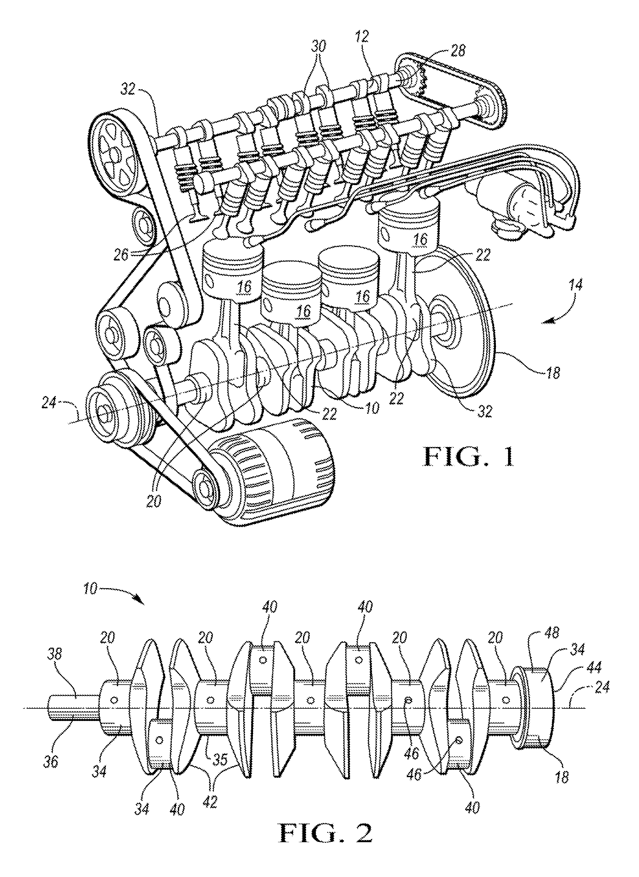
[0006] FIG. 1 depicts a schematic view of an example vehicle combustion engine including a crankshaft and a camshaft in accordance with one or more embodiments;
[0007] FIG. 2 depicts a perspective view of a laser hardened crankshaft;
[0008] FIG. 3 depicts a perspective view of a laser hardened camshaft;
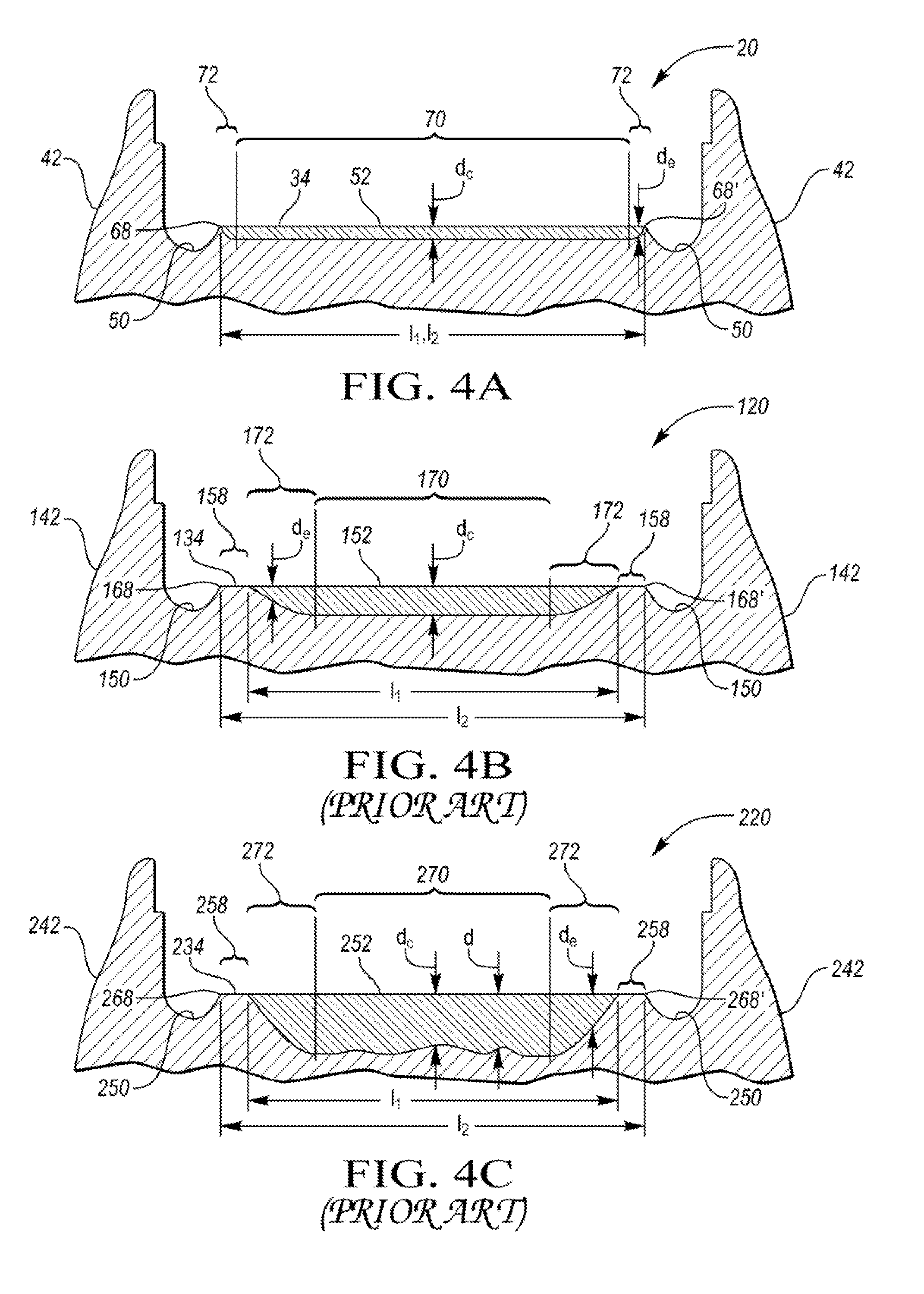
[0009] FIG. 4A depicts a schematic cross-sectional view of a laser hardened main journal of the crankshaft depicted in FIG. 2, the journal surface area having a case depth of less than about 1 mm;
[0010] FIG. 4B depicts a schematic cross-sectional view of a laser hardened main journal of a prior art crankshaft, the journal surface area having a case depth of about 1.2 mm;
[0011] FIG. 4C depicts a schematic cross-sectional view of an induction hardened main journal of a prior art crankshaft, the journal surface area having a case depth of about 2.5 mm;
[0012] FIG. 5 depicts a perspective view of a laser hardened portion of a crankshaft depicted in FIG. 2;
[0013] FIG. 6 depicts a perspective view of an induction hardened portion of a prior art crankshaft having induction hardened surfaces; and
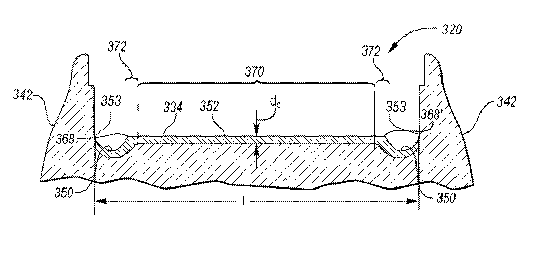
[0014] FIG. 7 depicts a schematic cross-sectional view of a laser hardened main journal, prepared for fillet rolling, of the crankshaft depicted in FIG. 2, the laser hardened surface extending the entire length between two outer edges of two undercut region.
DETAILED DESCRIPTION
[0015] Embodiments of the present disclosure are described herein. It is to be understood, however, that the disclosed embodiments are merely examples, and other embodiments may take various and alternative forms. The figures are not necessarily to scale; some features could be exaggerated or minimized to show details of particular components. Therefore, specific structural and functional details disclosed herein are not to be interpreted as limiting, but merely as a representative basis for teaching one skilled in the art to variously employ the present invention. As those of ordinary skill in the art will understand, various features illustrated and described with reference to any one of the figures may be combined with features illustrated in one or more other figures to produce embodiments that are not explicitly illustrated or described. The combinations of features illustrated provide representative embodiments for typical applications. Various combinations and modifications of the features consistent with the teachings of this disclosure, however, could be desired for particular applications or implementations.
[0016] Except where expressly indicated, all numerical quantities in this description indicating dimensions or material properties are to be understood as modified by the word "about" in describing the broadest scope of the present disclosure.
[0017] The first definition of an acronym or other abbreviation applies to all subsequent uses herein of the same abbreviation and applies mutatis mutandis to normal grammatical variations of the initially defined abbreviation. Unless expressly stated to the contrary, measurement of a property is determined by the same technique as previously or later referenced for the same property.
[0018] Crankshafts and camshafts are fundamental features in an automotive engine. FIG. 1 depicts a schematic view of an exemplary crankshaft 10 and camshaft 12 as internal portions of a combustion engine 14. A crankshaft 10 is a mechanical part able to perform a conversion between reciprocating motion and rotational motion. In an internal combustion engine 14 of a vehicle, a crankshaft 10 translates reciprocating motion of the pistons 16 into rotational motion which enables the wheels to drive a vehicle forward. The crankshaft 10 may be any crankshaft 10 within the cylinder block or in the cylinder head. The crankshaft 10 is connected to a flywheel 18, an engine block (not depicted) using bearings on a number of main journals 20, and to the pistons 16 via their respective rods 22 so that all pistons 16 of an engine 14 are attached to the crankshaft 10. The crankshaft 10 regulates the movement of pistons 16 as it moves the pistons 16 up and down inside the cylinders (not depicted). The crankshaft 10 has a linear axis 24 about which it rotates, typically with several bearing journals 20 riding on replaceable bearings held in the engine block (not depicted).
[0019] FIG. 1 further illustrates an exemplary camshaft 12. The camshaft 12 may be any camshaft 12 within the cylinder block or in the cylinder head. A camshaft 12 is used to operate valves 26 of internal combustion engines with pistons 16. It consists of a cylindrical rod 28 running the length of the cylinder bank (not depicted) and a number of lobes 30 protruding from it, one for each valve 26. The lobes 30 force the valves 26 open by pressing on the valve 26 as they rotate. The camshaft 12 is linked to the crankshaft 10. As the crankshaft 10 rotates, the camshaft 12 rotates along with it in a synchronized movement.
[0020] Crankshafts 10 and camshafts 12 can be monolithic or assembled from several pieces. Typically, these shafts 32 are forged from a steel bar through roll forging or casting in iron. The manufacturing process includes a number of steps, typically up to 25 operations including rough machining of the crankshaft, hardening, grinding or turning, and polishing. Most steel shafts 32 have induction hardened journal surfaces to increase their mechanical properties. Some high volume automotive and most high performance shafts use a more costly nitride process. Carburization and flame hardening are other exemplary methods of hardening. Yet, all of these technologies present a number of disadvantages, some of which are discussed below.
[0021] Induction hardening process has inherent drawbacks with respect to journal surface area coverage as induction hardening causes pattern proliferation and overheating of certain regions due to the nature of the inductive field. Difficulty of managing the physics of an induction field lie in applying it to desired regions while avoiding undesired regions. The current flow around oil holes during the induction hardening process typically causes bulging and necking conditions. Additionally, axial locating of inductors is often problematic. Coils and recipes must be designed to prevent both metallurgical damage in the chamfer area and pattern infringement into undercuts. These factors typically result in compromises with respect to hardness, surface coverage, and width of the surface hardening pattern. To obtain a higher percentage of surface coverage, a change in the journal design to a tangential journal design has been proposed. Yet, the design change still results in additional manufacturing compromises related to grinding and polishing.
[0022] Additionally, the typical case hardening methods induce distortion of the shaft. For example, induction hardening causes 50 to 70 .mu.m distortion or more in the shaft axis. Therefore, it is customary that the amount of material removed in the finishing operation and process positioning errors be accounted for and added to the desired finish case depth. This requires that the hardening case depth be increased which may be accomplished by increasing heat time and/or power supply current. High frequency induction hardening typically produces a case depth of about 1.5 mm to 3 mm which represents an adequate case depth and enables remanufacturing without subsequent retreating. Yet, the product requires grinding after treating. Thus, the typical case depth before grinding is about 1.5 mm to 3 mm, but the case depth of an induction-hardened crankshaft or camshaft in a finished state is not less than 0.5 mm. Shallower case depths are difficult to achieve with the induction process due to the level of manageable field strength and quench control.
[0023] Furthermore, the finishing process results in a relative increase in residual tensile stresses. To avoid tensile stresses, lower productivity grind cycles must be employed. To measure absolute stress, costly and time-consuming X-Ray diffraction must be utilized. Despite these efforts, the grind-harden sequence always results in some loss of desirable compressive stress. Compressive residual stress in the journal surfaces helps prevent cracks from forming and is generally good for fatigue properties.
[0024] The typical hardening methods present additional drawbacks. For example, coils are used for induction hardening. These copper coils have to be changed any time a new geometry on a journal is introduced. Coils are perishable tooling and must be regularly replaced or reworked from cycling damage. Such change is very costly and time consuming. Furthermore, a quench fluid and high electromagnetic field used during induction hardening present environmental and health challenges.
[0025] Nitriding has a number of disadvantages as well. For example, it is a relatively time consuming process, taking at least 8 hours. Additionally, the resulting depth of the hardened surface is relatively shallow, about 0.01 mm to 0.015 mm after a minimum of an 8-hour-long process, and the shaft has to be retreated if it is ever reground for service. While deeper depths can be obtained via nitriding, substantially longer time is required to achieve the depths deeper than 0.015 mm. The maximum case depth is limited to about 0.5 mm, and time to achieve this depth is about 120 hours which renders this method impractical for high volume applications. Nitriding also produces an undesirable white layer on the surface of the shaft, requiring removal by polishing of the surface after processing.
[0026] Additionally still, crankshaft fatigue strength in journals has traditionally been improved by increasing journal compressive stress via rolling or the above-mentioned induction hardening/nitriding. Yet, a combination of both methods is traditionally not used because the induction hardened martensitic microstructure is brittle, even in a tempered state, prone to cracking, especially when subsequent mechanical fillet rolling loads are applied.
[0027] If both fillet rolling and induction hardening is employed, high fracture rates are observed. Further still, straightening capabilities after the rolling process, which is normally performed in the fillet rolling machine after soft rolling, is generally omitted, and higher grind stock levels must be employed to accommodate heat treat shaft distortion. The potential fracture zones coincide with peak stress areas within the crankshaft when in operation, which may lead to crankshaft or engine fatigue failure. To prevent such event, all of such crankshafts require checking with magnetic particle inspection (MPI), which presents a labor and time intensive process with subjective results and only 80% effectiveness due to the required human element.
[0028] Therefore, it would be desirable to provide a method of shaft surface hardening which would overcome one or more limitations of the previously devised manufacturing methods. It would be desirable to provide a low-distortion hardening method which would increase the overall hardened journal surface area, allow for wider surface hardening pattern of journal surfaces, and eliminate necking as well as the need to grind out the distortions which occur during the induction hardening process. Additionally, it would be desirable to develop a hardening method which would eliminate the soft zone around the oil hole on a journal. Additionally still, it would be desirable to provide a flexible hardening method which would result in cost and time savings, reduce cycle time, eliminate the need for finish grind stock from the total case depth, eliminate copper coil tooling, and increase environmental safety by eliminating quench fluid and high electromagnetic field. It would also be desirable to further increase fatigue strength, provide a more uniform case depth across the journal surface, and simplify the case pattern inspection process.
[0029] Laser hardening represents an alternative method of hardening precision journal surfaces for enhanced wear properties. Yet, the current laser methods have focused on replication of induction patterns and case depths. The laser maximum case depth is limited by metallurgical surface damage caused by overheating. Thus, the laser-hardened case depth prior to grind on a typical laser-hardened crankshaft is about 1.2 mm. Unlike induction-hardened case depths, laser-hardened minimal case depths can be achieved without risk. At maximum depth of about 1.2 mm, overheating of the undercut regions dictates the width of the hardening pattern with respect to crankshaft fatigue requirements and limits the hardening pattern to up to about 85% of the journal surface area.
[0030] It has now been surprisingly discovered that the minimum case depth requirements may be reduced below 1.2 mm while delivering satisfactory wear properties, enabling refurbishment or regrinding of the components without retreatment, and maximizing throughput with the laser hardening process. Additionally, since the case depth of the laser hardening process affects processing time, lowering the case depth requirements significantly reduces cycle time by up to 50% or more.
[0031] According to one or more embodiments, a method is provided which includes subjecting a shaft 10, 12 to laser hardening, specifically, laser hardening one or more surface areas of a shaft 10, 12. FIGS. 2 and 3 depict non-limiting examples of a crankshaft 10 and a camshaft 12, respectively. Each shaft 10, 12 includes one or more surfaces 34 to be hardened which form a band 35 around a perimeter of the journal. FIG. 2 depicts an exemplary crankshaft 10 having a post 36 at the first end 38, main journals 20, and pin/rod journals 40 connected to a plurality of counterweights or bearings 42 via undercut regions (not depicted), and a flywheel 18 at the second end 44. The main journals 20, also called the main bearing journals or fillets, include an oil hole 46 which serves for distribution of lubricating oil to the bearings. The pin journals 40, also known as crankpins or crankpin fillets, also include an oil hole 46. The crankshaft 10 further includes oil ducts facilitating lubrication, which are not depicted. The crankshaft 10 may further include an oil seal 48 located on the flywheel 18. FIG. 3 depicts a non-limiting example of a camshaft 12 having a cylindrical rod 28, a plurality of main journals 20, and a plurality of lobes 30.
[0032] As is depicted in FIGS. 2 and 3, the one or more surfaces 34 to be hardened may include a surface on a main journal 20, a pin journal 40, an oil seal 48, a lobe 30, or a running surface 62. The number of main journals 20, pin journals 40, oil seals 48, lobes 30, and their respective surfaces to be hardened may differ and depend on the desirable parameters of the shaft 32 which is being manufactured. A running surface 62 may be any cylindrical or shouldered surface or any surface in contact with a journal such as a bushing surface 64 or a shouldered wall surface 66.
[0033] The method may include a step of generating a surface hardening pattern from a 3-D model of the shaft 32 to be laser hardened. The method may include a step of programming a microprocessor unit (MPU) to generate the surface hardening pattern. In one or more embodiments, the generated surface hardening pattern may include a series of preselected points, a portion of, or the entire surface geometry of the shaft 10, 12. The surface hardening pattern may include one or more surfaces 34 on one or more main journals 20, pin journals 40, lobes 30, oil seals 48, or running surfaces 62.
[0034] The method may include determining dimensions of the surface area to be hardened. The method may include a step of adjusting a spot size of the laser beam according to the dimensions of the surface area to be hardened, specifically the depth and width of the surface area to be hardened 34. The method may include a step of directing a laser beam from the laser power unit to the surface 34 of the shaft 10, 12 to be laser hardened according to the surface hardening pattern. The method may include adjusting one or more parameters of the surface hardening pattern before and/or during the laser hardening operation.
[0035] In one or more embodiments, the laser hardening may be facilitated by at least one laser power unit. A plurality of laser power units may be utilized. For example, one laser power unit may be used for tempering the surfaces 34 to be hardened. Such laser could be a lower power laser such as a 1.0 kW laser. The second laser power unit could be a high power laser unit facilitating the hardening. The high power unit could be, for example, a 6.0 kW laser. A laser power unit having a different power may be used, for example any laser having power ranging from 500 W to 50 kW may be suitable. Alternatively, both tempering and hardening may be facilitated by one laser power unit. Alternatively still, tempering may be omitted because the laser microstructure is less than 100% martensitic. The temperature to be achieved during the hardening process should not exceed about 1260.degree. C. to prevent overheating of the shaft material.
[0036] The method contemplates using different types of lasers as the heat source for the hardening operation. Exemplary non-limiting examples of suitable lasers include lasers having different types of active gain media. The gain media may include liquid such as dye lasers in which the chemical make-up of the dye determines the operational wavelength. The liquids may be organic chemical solvent such as methanol, ethanol, and ethylene glycol containing a dye such as coumarin, rhodamine, and fluorescein. The gain media may include gas such as CO.sub.2, Ar, Kr, and/or gas mixtures such as He--Ne. The gain medium may be metal vapor such as Cu, HeCd, HeHg, HeSe, HeAg, or Au. The gain media may include solids such as crystals and glass, usually doped with an impurity such as Cr, Nd, Er, or Ti ions. The solid crystals may include YAG (yttrium aluminum garnet), YLF (yttrium lithium fluoride), LiSAF (lithium strontium aluminum fluoride), or sapphire (aluminum oxide). Non-limiting examples of solid-state gain media doped with an impurity include Nd:YAG, Cr:sapphire, Cr:LiSAF, Er:YLF, Nd:glass, or Er:glass. The gain medium may include semiconductors having a uniform dopant distribution or a material with differing dopant levels in which the movement of electrons causes laser action. Non-limiting examples of semiconductor gain media may include InGaAs, GaN, InGaN, and InGaAsP. The laser may be a high power fiber laser created from active optical fibers doped with rare earth ions and semiconductor diodes as the light source to pump the active fibers.
[0037] The at least one laser power unit may be connected to the MPU also known as a central processing unit capable of accepting digital data as input, processing the data according to instructions stored in its memory, and providing output. The MPU may include mathematical modeling software which is capable of processing input data. Exemplary input data may include information about a 3-D model of a shaft 32 having surfaces 34 to be hardened; parameters for new geometry such as hardening width, energy balance, or the like; parameters relating to oil holes such as the oil hole radius, offset from the center of a journal, or the like.
[0038] The method implements laser hardening into the depth of less than 1.2 mm, 1.0 mm, 0.8 mm, or 0.5 mm. At these depths as well as at deeper case depths, distortion of the main journals 20 is only minimal in comparison with induction hardening. The distortion of the main journals 20 caused by laser hardening may be about 5 .mu.m to 10 .mu.m. In comparison, an induction-hardened shaft may feature about 50 .mu.m to 70 .mu.m distortion or more on the main journals. Therefore, the laser hardening process distortion levels even at deeper depths are such that heat-related distortion is manageable. The laser-hardened case depth can be reduced to less than about 1 mm also because accounting for grinding stock to compensate for induction hardening distortions is no longer necessary. This in turn enables significantly shorter cycle time. Increasing scan speeds at the same or lower power levels can achieve hardening shallower case depths in a shorter time.
[0039] The method may include hardening one or more surfaces 34 to the case depth of about 0.05 mm to 1.1 mm, 0.15 mm to 0.8 mm, or 0.2 mm to 0.5 mm. For example, if the requirements of the final product are 0.2 mm, hardening may be done to the depth of 0.6 mm to 0.7 mm. Laser hardening may save up to 50% of cycle time associated with hardening of a shaft 32 that requires a hardening depth of more than about 1.2 mm. Hardening shallower than about 0.5 mm contributes to even shorter cycle time as less time is required for scanning and applying heat to the surfaces 34. Unlike the prior art shafts, the laser hardened shaft 32 of the present disclosure may be reground and/or remanufactured without repeating the hardening operation even if the case depth is only about 0.2 mm.
[0040] The shallow case depth of less than about 1 mm enables wider laser hardening pattern than the patterns achievable while implementing case depth deeper than about 1.2 mm. The pattern may expand closer to the edges of the surfaces 34 or reach the very edges of the surfaces 34. The wider pattern may include up to 100% surface area of the one or more surfaces 34 to be laser hardened such that the band 35 does not contain any unhardened portions 58. The wider pattern includes more than 80%, 85%, 90%, 95%, or 99% of the one or more surfaces 34 to be laser hardened and/or of the band 35. As can be seen in FIG. 4A, which depicts a profile of an exemplary journal contact surface which is laser hardened 34 having a shallow case depth of less than about 1 mm, the laser hardened area extends from crest 68 to crest 68' which is defined by two undercut regions 50.
[0041] In comparison, only up to 80% of a journal surface area 134 having a depth of about 1.2 mm may be laser hardened, as FIG. 4B illustrates. Laser hardening a wider pattern to the depth of about 1.2 mm could jeopardize the journal strength as it could induce conditions which generate risk to subsequent fillet rolling operations and/or negatively impact the undercut regions 50 by overheating. The laser hardened layer 152 depicted in FIG. 4B does not reach the crests 168, 168'. And only up to 85% of a journal surface area 234, depicted in FIG. 4C, having a case depth of about 2.5 mm and being hardened by an induction process may be hardened. Just as the layer 152 in FIG. 4B, the laser hardened layer 252, illustrated in FIG. 4C, is not wide enough to extend across the entire distance between the crests 268 and 268' defined by the undercut regions 250. Specifically, clamshell induction hardening may achieve hardening of only up to 75% surface area and orbital induction hardening up to 85% surface area. Thus, providing shallow case depth laser hardening enables a significantly wider surface hardening pattern. The unhardened areas are depicted in FIGS. 4B and 4C as 158 and 258, respectively.
[0042] A perspective view of a journal 20 having near-100% journal surface area laser-hardened is depicted in FIG. 5. As FIG. 5 illustrates, the laser-hardened journal 20 of a shaft 32 may include a hardened surface area 52 directly adjacent to the edge 54 of the oil hole 46 and extending between crests 68, 68' defining edges 56 of the undercut regions 50. The oil hole 46 and the undercut regions 50 are free from metallurgical transformation. The surface area of the oil hole 46 and the undercut regions 50 thus remain completely unhardened.
[0043] In contrast, a clamshell induction-hardened journal 220 is depicted in FIG. 6. The hardened surface area 252 on the journal 240 does not include the area adjacent to the oil hole 246 and the area adjacent to the undercut regions 250. The journal 220 of FIG. 6 thus includes non-hardened areas 258 which remain soft. The dimensions of the soft area 258 around the oil hole 246 may reach up to 2-3 mm radially around the oil hole 246. The soft area 258 contributes to undesirable fatigue stress and lower bearing seizure resistance. Additionally, induction hardening of the acute side of the oil hole 246 presents other challenges such as difficulty in preventing overheating of the cross sectional area of the oil hole 246. Such overheating induces damage which in turn affects fatigue strength. Adjusting the induction hardening process to alleviate overheating would in turn result in a compromised level of hardness or soft spots 258. Additionally, traditional induction hardening may affect the surface area of the oil hole 246 and/or the area of the undercut regions 250 such that the areas 246 and/or 250 are heat-affected and subjected to undesirable metallurgical changes.
[0044] As can be further seen in FIG. 6, induction hardening causes necking or narrowing of the induction pattern as the current flows around the oil hole 246 and/or the undercut regions 250. The absence of ferrous volume around the oil hole 246 and the undercut regions 250 results in higher current flow, resulting in bulging of the pattern at the oil hole 246 and around the undercut regions 250. To avoid necking, induction coil design and/or the amount of current has to be adjusted as necking presents a fatigue stress concern. Yet, when the coil design and/or current are reduced, the area near the oil hole 246 and the undercut regions 250 results in a narrower, necked, pattern. In contrast, due to the nature, flexibility, and precision of laser hardening, the laser-hardened journal 20 is free of necking, as FIG. 5 illustrates.
[0045] Referring back to FIGS. 4A-4C, it can be seen that the laser hardened layer 52 in FIG. 4A features different dimensions and a shape of the profile than the hardened layers 152 and 252 depicted in FIGS. 4B and 4C, respectively. The laser hardened layer 52 in FIG. 4A includes a central region 70 and end regions 72. The layer 52 has a length l.sub.1, the distance between crests 68 and 68' is designated as length l.sub.2. l.sub.1 may equal l.sub.2 in at least a portion of the layer 52 such as the very top portion at the journal surface 34. As a result, the crest-to-crest contact surface area does not contain any unhardened portions. Alternatively, l.sub.1 may equal l.sub.2 throughout the entire depth of the layer 52, or at least in 50%, 60%, 70%, 80%, 90% or more of the depth of the layer 52.
[0046] The layer 52 may be about 1 mm or less deep, as was described above. The central region 70 may have a depth d.sub.c, which may be substantially the same or constant throughout the entire central region 70. The end regions 72 of the layer 52 may have the same or different depth d.sub.e than the depth of the central region 70 d.sub.c. The depth d.sub.c may equal or be greater than d.sub.e. The depth d.sub.e of the end regions 72 depends on the shape of the end regions 72. The end regions 72 may have a substantially square pattern or rounded shape. Other shapes are contemplated. For example, if the shape of the end regions 72 is substantially square, the depth d.sub.e may be the same or substantially similar as the depth d.sub.c. The depth of the layer 52 may thus be constant or substantially the same in about 70%, 72%, 74%, 76%, 78%, 80%, 84%, 86%, 88%, 90%, 92%, 94%, 96% or more of the layer 52.
[0047] Unlike the layer 52, the laser hardened layer 152 depicted in FIG. 4B has a depth greater than 1 mm, specifically about 1.2 mm, as was referenced above. The end regions 172 do not have a substantially square profile and feature a triangular shape or rounded shape. Thus, the depth d.sub.e varies throughout the end regions 172 and is not substantially the same as the depth d.sub.c in the central region 170. The depth in the central region d.sub.c is greater than the depth in the end regions d.sub.e. Due to the varying depth of the end regions 172, the depth of the layer 152 may be the same in up to about 65% of the layer 152. The length l.sub.1 of the hardened layer 152 is smaller than the distance between crests 168 and 168' designated as length l.sub.2 such that soft or unhardened portions 58 remain between the layer 152 and the undercut regions 150.
[0048] Likewise, the profile of the induction-hardened surface 252 differs from the profile of the layer 52 as the layer 252 typically displays irregularities such as protrusions or peaks 269 and a central concave region 270. The depth of the layer 252 thus differs throughout the layer 252. Specifically, the depth d.sub.c within the central region 270 is smaller than the depth d outside of the central region due to concavity which is inherent with the induction process. Additionally, the end regions 272 are rounded, may feature a shape of a triangle, or both and do not feature a square pattern. The depth of the end regions 272 d.sub.e differs throughout the end regions 272. The depth d.sub.e is smaller than the depth d, and may be smaller or greater than d.sub.c. The depth of the layer 252 may be about 2.5 mm to 3 mm or greater prior to grinding, as was explained above. Due to the varying depth of the end regions 172, the central region 270, and the irregularities in the region outside of the central region 270, the depth of the layer 252 may be substantially the same in only up to about 55% of the layer 252. The length l.sub.1 of the layer 252 is smaller than the distance between crests 268 and 268' designated as length l.sub.2 such that unhardened portions 58 remain between the layer 252 and the undercut regions 250.
[0049] The journal profile may be straight or crown or barrel-shaped, thus non-straight. Straightness relates to a profile being uniformly level/straight with no defined barrel shape. The crown profile may have a relatively large radius or a prescribed level of barrel defined by about 1.5 .mu.m to 3 .mu.m radially. The barrel-shape relates to a convex shape. An hourglass or concave shape is not desirable as it may result in isolated peak loading of the journals. The barrel-shape may be added to accommodate, for example, cylinder block bulkhead deflections or a crankshaft deflection due to firing loads which may effectively close the crank pins, resulting in undesirable pin-loading of main journals 20. Whether the profile shape is straight or barrel-shaped, consistent profile is required. While an induction process must use a narrower pattern or abandon the fillet rolling and straightening method, the laser method can harden a band 35 closer to the undercuts 50, the unhardened area 58 is reduced, and subsequent profile is more uniform when compared to the induction hardened profile. The laser method also allows utilization of the fillet rolling which results in straightening shafts more readily and lowers grind stock levels while also providing near-100% hardened journal area 52 while increasing the effective bearing width.
[0050] The difference between the profiles depicted in FIGS. 4A-4C may be also expressed as the rate of change of the profile. The rate of change may be defined as .mu.m of change in a length. Since the irregularities in the profile such as the afore-mentioned peaks 269 and the concavity in the central region 270 may result in journal failure, elimination of the irregularities and concavity is a goal. A straighter profile, or a profile with lower rate of change of the profile, provides more contact surface area to provide bearing support which translates into an increased lifetime of the journal. The induction-hardened layer 252 typically has the rate of change of about 1 .mu.m in 2-3 mm. Utilizing the method disclosed herein, a rate of change of 1 .mu.m in 2 mm or less may be achieved. Laser hardening thus enables a higher degree of control over straightness of the profile and/or profile uniformity than induction hardening.
[0051] The rate of change and straightness of the laser heat-treated surfaces on the main journals 20 of a crankshaft were measured via an Adcole High-Speed Crankshaft Gage measuring machine manufactured by the Adcole Corporation. The machine provides robot-fed 100% crankshaft inspection having submicron accuracy and presents a recognized standard in camshaft and crankshaft gauging. The results are provided in Table 1 below. The induction hardened surfaces on the main journals 220 of an induction-hardened crankshaft were obtained using the same machine, results of which are referenced in Table 2 below. Comparison of the data in both tables shows that the average straightness achievable by the laser heat treatment is nearly 50% better than straightness attainable via an induction process.
TABLE-US-00001 TABLE 1 Straightness of main journal laser hardened surfaces on a laser hardened crankshaft Main journal 1 Main journal 2 Main journal 3 Main journal 4 Average Crankshaft straightness straightness straightness straightness straightness no. [.mu.m] [.mu.m] [.mu.m] [.mu.m] [.mu.m] 1 1.4 1.9 1.9 1.3 1.6 2 1.2 1.8 1.7 1.7 1.6 3 1.2 1.8 1.4 1.5 1.5 4 1.0 1.9 1.6 1.8 1.6 5 1.1 1.5 1.5 2.0 1.5 6 1.4 1.2 0.7 1.2 1.1 7 1.6 1.5 0.8 1.5 1.4 8 0.9 1.2 0.9 2.0 1.3 9 1.1 1.3 1.1 1.8 1.3 10 1.4 1.9 1.0 1.5 1.5
TABLE-US-00002 TABLE 2 Straightness of main journal induction hardened surfaces on an induction hardened crankshaft Main journal 1 Main journal 2 Main journal 3 Main journal 4 Average Crankshaft straightness straightness straightness straightness straightness no. [.mu.m] [.mu.m] [.mu.m] [.mu.m] [.mu.m] 1 1.6 2.3 2.4 2.1 2.1 2 2.1 2.7 3.2 2.5 2.6 3 2.1 2.6 3.5 2.2 2.6 4 1.9 2.9 2.7 2.6 2.5 5 2.7 2.9 3.5 2.6 2.9 6 2.1 2.4 3.6 3.1 2.8 7 1.6 2.2 2.1 1.8 1.9 8 1.8 2.0 2.4 2.0 2.1 9 2.0 2.2 2.3 2.1 2.2 10 1.9 2.1 2.4 2.0 2.1
[0052] Due to advantages mentioned above, laser hardening may be applied when it is desirable to harden all of the journal surfaces except the undercut region 50, the oil hole 46, or a combination thereof. Thus, crankshafts 10 which require seal surface hardening may be processed via laser hardening as well. The method may be likewise applied to camshafts 12. One of the advantages of laser-hardening camshaft 12 surfaces such as main/cam journals 20 or lobes 30 is limiting overheating of these surfaces which may typically have a tendency to overheat due to a lack of heat sink. Thus, a narrow hardening pattern typical for the cam journals 20 and lobes 30 could be widened up to about 80%, 90%, or 100% of cam journal surface or lobe surface while preventing metallurgical damage to the surfaces.
[0053] In one or more embodiments, the method may include additional manufacturing steps after the shaft 32 is laser hardened. In at least one embodiment, the method may include polishing. Polishing may include any conventional method of polishing of a metal surface of a laser hardened shaft 32. The method may include removal of certain amount of material stock.
[0054] Additionally still, the above-described method may provide a consistent, near-100% hardened journal surface area while ensuring no infringement into the undercut fatigue zone 50 which otherwise poses reliability risk. The method also presents an additional advantage over induction hardened tangential fillet designs.
[0055] In one or more embodiments, the laser process described above may utilize fillet rolling, which enables straightening of the shaft 32 before grinding such that the grind stock may be reduced. Thus, utilization of the laser technique and fillet rolling offers up to 100% hardened journal surface and roll straightening. On the other hand, to achieve a maximum achievable hardening pattern with induction hardening, additional grind stock must be added due to greater distortion. Additionally, as was stated above, an induction hardened journals with undercuts in combination with fillet rolling may lead to crankshaft failure such as a cracked crankshaft and low fillet rolling tool life.
[0056] Fillet rolling or deep rolling is a radially symmetrical deformation process which may be used for surface finish, hardness, and/or residual stress control. Fillet rolling may be used to strengthen journal fillets. In one or more embodiments, a method of treating a shaft fillet via laser hardening and subsequent fillet rolling is disclosed. The method includes laser hardening a fillet surface, depicted in FIG. 7, to a depth d to induce compressive stresses into the surface. The surface may be a green fillet surface. The surface may be a green machined surface. The depth d may equal the depth d.sub.c as depicted in FIG. 4A. Unlike in FIG. 4A, the laser-hardened surface or layer 352 does not extend just crest-to-crest 368-368', but the laser-hardened surface or layer 352 extends the entire length l between outer edges 353 of two undercut regions 350 of the journal 320. The laser-hardened surface 352 is thus inclusive of both undercuts 350, both crests 368', both end regions 372, and the central region 370. The surface may include about 80 to 100% fillet contact area. The surface 352 may include about 70, 80, 85, 90, 95, 98, 100% of the journal area.
[0057] The depth d or d.sub.c, as depicted in FIG. 7 may be uniform, substantially the same or constant in the entire layer 352. Alternatively, the depth may vary such that the depth at the outer edges 353 may be smaller than the depth in the central region 370, at the end regions 372, at the lowest point of the undercut region 350, or a combination thereof. The layer 352 substantially follows the shape of the central region 370, the end regions 352, and the undercut region 350. The depth of the layer 352 may thus be constant or substantially the same in about 70%, 72%, 74%, 76%, 78%, 80%, 84%, 86%, 88%, 90%, 92%, 94%, 96% or more of the layer 352. The depth d.sub.c in FIG. 7 may be about 0.8 mm to 1.0 mm. The depth d.sub.c in FIG. 7 may also be about 1.25-1.5 mm.
[0058] The method further includes fillet rolling or deep rolling to apply additional compressive stress to the laser-hardened surface 352. The fillet rolling is performed in such a way that the depth d or d.sub.c, as depicted in FIG. 7, is maintained along the entire length l. The depth d may be maintained during a subsequent operation such as grinding or remanufacturing.
[0059] The fillet rolling may follow immediately after laser-hardening of the journal surface. Alternatively, the fillet rolling may follow after another operation such as polishing.
[0060] The combined laser hardening and fillet rolling enables a more uniform case depth across the journal surface and simplifies the case pattern inspection process because the entire width or length l between journal collars or the outer edges 353 of the undercut regions 350 may be hardened.
[0061] Without limiting the disclosure to a single theory, the combined method yield success because the laser hardening does not generate a fully martensitic structure as the phase transformation in the journals is captured via air quenching instead. Yet, the laser hardening provides sufficient increase in hardness/compression strength to meet the desired levels for bearing journal seizure resistance. Thus, the microstructure produced by the laser hardening process in the fillet areas enables increased fillet rolling loads which may be applied onto the laser-treated surface of the journal in comparison with fillets which were unhardened and subsequently rolled or hardened by traditional methods such as induction hardening and subsequently rolled.
[0062] Typically, unhardened or induction-hardened fillet rolling loads are limited by material displacement or roller penetration, which when exceeded, may result in skidding or failure of the roller. For example, induction-hardened fillets, having martensitic microstructure, being rolled may be very susceptible to fracture and distortion at the load of about 10 to 12 kN.
[0063] But laser-hardening of the fillet area provides a sufficiently strong, hardened, but not brittle surface or layer having a mixed microstructure, which is not subject to fracture, but which reduces material displacement. The combination of these properties allows increase of fillet rolling loads. Thus, while the fillet rolling load is specific to a specific application and depends on various factors such as fatigue requirements, parent material type, roller radius, roller size, and angle, example fillet rolling loads for the herein-disclosed laser-hardened fillets/journals may be about 5 to 15 kN, 8 to 14 kN, or 10 to 12 kN. The fillet rolling may be performed at the loads of, for example, about 10 to 15 kN or 11 to 15 kN.
[0064] The higher rolling loads result in higher level of compression. The greater compressive stress applied via fillet rolling onto the fillet laser-hardened areas results in improved fatigue strength. The improved fatigue strength, in turn, helps avoid a change in the base material alloy, which may prevent increase in raw material cost and productivity loss due to machinability.
[0065] The method also enables a wider case pattern, yielding greater hardened journal bearing surface area, as case depth may remain uniform through the journal 370 from one outer edge 353 of the first undercut region 350 to the outer edge 353 of the second undercut region 350. As a result, there may be no loss in length/width l of the treated area after subsequent operation or operations such as grinding, regrinding, remanufacturing, and/or undersize grinding as the pattern transition remains outside of the ground zone. This presents an advantage for both initial and subsequent remanufacture grinding operations.
[0066] Additional advantages of the disclosed method thus lie in achieving higher fillet compressive stress levels while preserving the ability to straighten without fracture and avoiding additional grind stock on journals to accommodate distortion. Risk of fracture is greatly reduced, compared to rolled fillets which were previously hardened by traditional hardening methods described above. As a result, 100% MPI is not required for the laser-hardened fillet-rolled journals. Additionally, the case hardened pattern may be expanded to 100% coverage of the journal, increasing overall engine bearing load bearing capacity and seizure resistance. The process also simplifies the manufacturing process for applying case hardening pattern as the pattern no longer must be confined between fillet edges or end regions 372. Since 100% of journal surface may be hardened as migration into fillet zones is no longer a concern, there is a greater level of seizure resistance.
[0067] The method of laser-hardening and subsequent fillet rolling is applicable to a crankshaft, camshaft, main journals, pins journals, posts, any portion that requires fillet rolling, or a combination thereof. While automotive shafts and journals are mentioned, the method likewise applies to other engine applications such as shafts and journals for compact utility tractors, motorcycles, and small engine harden/utility applications.
[0068] While exemplary embodiments are described above, it is not intended that these embodiments describe all possible forms of the disclosure. Rather, the words used in the specification are words of description rather than limitation, and it is understood that various changes may be made without departing from the spirit and scope of the disclosure. Additionally, the features of various implementing embodiments may be combined to form further embodiments of the disclosure.
* * * * *
D00000
D00001
D00002
D00003
D00004
XML
uspto.report is an independent third-party trademark research tool that is not affiliated, endorsed, or sponsored by the United States Patent and Trademark Office (USPTO) or any other governmental organization. The information provided by uspto.report is based on publicly available data at the time of writing and is intended for informational purposes only.
While we strive to provide accurate and up-to-date information, we do not guarantee the accuracy, completeness, reliability, or suitability of the information displayed on this site. The use of this site is at your own risk. Any reliance you place on such information is therefore strictly at your own risk.
All official trademark data, including owner information, should be verified by visiting the official USPTO website at www.uspto.gov. This site is not intended to replace professional legal advice and should not be used as a substitute for consulting with a legal professional who is knowledgeable about trademark law.