Implants For Adding Joint Inclination To A Knee Arthroplasty
Yager; Edward R.
U.S. patent application number 16/179201 was filed with the patent office on 2019-05-16 for implants for adding joint inclination to a knee arthroplasty. The applicant listed for this patent is Zimmer, Inc.. Invention is credited to Edward R. Yager.
| Application Number | 20190142594 16/179201 |
| Document ID | / |
| Family ID | 64316451 |
| Filed Date | 2019-05-16 |
| United States Patent Application | 20190142594 |
| Kind Code | A1 |
| Yager; Edward R. | May 16, 2019 |
IMPLANTS FOR ADDING JOINT INCLINATION TO A KNEE ARTHROPLASTY
Abstract
According to one example, a bearing component for a knee arthroplasty is disclosed. The bearing component can optionally comprise any one or combination of: a medial compartment having an medial articular surface with a medial articular track and having a first thickness as measured at the medial articular track between the medial articular surface a medial distal surface; and a lateral compartment having a lateral articular surface with a lateral articular track and having a second thickness as measured at the lateral articular track between the lateral articular surface a lateral distal surface; wherein the medial articular surface at the medial articular track and the lateral articular surface at the lateral articular track each have an inclination so as to form an acute angle with respect to a resected proximal surface of a tibia.
| Inventors: | Yager; Edward R.; (Fort Wayne, IN) | ||||||||||
| Applicant: |
|
||||||||||
|---|---|---|---|---|---|---|---|---|---|---|---|
| Family ID: | 64316451 | ||||||||||
| Appl. No.: | 16/179201 | ||||||||||
| Filed: | November 2, 2018 |
Related U.S. Patent Documents
| Application Number | Filing Date | Patent Number | ||
|---|---|---|---|---|
| 62587192 | Nov 16, 2017 | |||
| Current U.S. Class: | 623/20.15 |
| Current CPC Class: | A61F 2002/3895 20130101; A61F 2/3886 20130101; A61F 2002/30604 20130101; A61F 2/4684 20130101; A61F 2/389 20130101; A61F 2/385 20130101 |
| International Class: | A61F 2/38 20060101 A61F002/38 |
Claims
1. A bearing component for a knee arthroplasty, the bearing component comprising: a medial compartment having an medial articular surface with a medial articular track and having a first thickness as measured at the medial articular track between the medial articular surface a medial distal surface; and a lateral compartment having a lateral articular surface with a lateral articular track and having a second thickness as measured at the lateral articular track between the lateral articular surface a lateral distal surface; wherein the medial articular surface at the medial articular track and the lateral articular surface at the lateral articular track each have an inclination so as to form an acute angle with respect to a resected proximal surface of a tibia.
2. The bearing component of claim 1, the inclination is in a varus-valgus and proximal-distal direction only.
3. The bearing component of claim 1, wherein the bearing component is a monolithic single piece construct forming both the medial compartment and the lateral compartment.
4. The bearing component of claim 1, wherein the bearing component comprises a two-piece bearing having the medial compartment separated from the lateral compartment.
5. The bearing component of claim 1, wherein the inclination occurs at dwell points of the medial and lateral articular tracks.
6. The bearing component of claim 1, wherein the inclination occurs for only a portion of an anterior-posterior extent of at least one of the medial articular track and the lateral articular track.
7. The bearing component of claim 1, wherein the inclination occurs for substantially an entirety of an anterior-posterior extent of at least one of the medial articular track and the lateral articular track.
8. The bearing component of claim 1, wherein the knee arthroplasty comprises one of a partial knee arthroplasty or a total knee arthroplasty.
9. A tibial baseplate for a knee arthroplasty, the tibial baseplate comprising: a distal surface configured to interface with and mount on a resected proximal surface of a tibia; a proximal surface opposing the distal surface and configured to couple with a bearing component, the proximal surface having an inclination in a varus-valgus direction so as to form an acute angle with respect to at least one of the resected proximal surface of the tibia and the distal surface.
10. The tibial baseplate of claim 9, further comprising: a medial portion; a lateral portion opposing the medial portion, wherein a thickness of the lateral portion as measured between the proximal surface and the distal surface along a medial-lateral extent of the lateral portion that differs from a thickness of the medial portion as measured between the proximal surface and the distal surface along a medial-lateral extent of the medial portion.
11. The tibial baseplate of claim 10, wherein the medial portion comprises a first component and the lateral portion comprises a second component, and wherein the first component is separate from the second component.
12. The tibial baseplate of claim 9, wherein the tibial baseplate is separated into at least two components comprising at least a medial component and a lateral component.
13. A system for a knee arthroplasty comprising: a plurality of trial tibial baseplates, each of the plurality of trial tibial baseplates are configured to seat on one or more resected portions of the tibia, wherein at least some of the plurality of trial tibial baseplates have a proximal surface with an inclination in a varus-valgus direction relative to a distal surface thereof so as to form an acute angle therebetween, and wherein the at least some of the plurality of trial tibial baseplates are differently configured relative to one another to provide for a different degree for the acute angle; and a plurality of trial bearing components each configured to couple with one or more of the plurality of trial tibial baseplates, wherein at least some of the trial bearing components each comprise: a medial compartment having an medial articular surface with a medial articular track and having a first thickness as measured at the medial articular track between the medial articular surface a medial distal surface, and a lateral compartment having a lateral articular surface with a lateral articular track and having a second thickness as measured at the lateral articular track between the lateral articular surface a lateral distal surface, wherein the medial articular surface at the medial articular track and the lateral articular surface at the lateral articular track each have an inclination so as to form an acute angle with respect to a resected proximal surface of a tibia, wherein the at least some of the plurality of bearing components are differently configured relative to one another to provide for a different degree for the acute angle.
14. The system of claim 13, wherein the inclination of the at least some of the plurality of bearing components is in a varus-valgus and proximal-distal direction only.
15. The system of claim 13, wherein the at least some of the plurality of bearing components each are a monolithic single piece construct forming both the medial compartment and the lateral compartment.
16. The system of claim 13, wherein the at least some of the plurality of bearing components each comprise a two-piece bearing having the medial compartment separated from the lateral compartment.
17. The system of claim 13, wherein the inclination of the at least some of the plurality of bearing components occurs at dwell points of the medial and lateral articular tracks.
18. The system of claim 13, wherein the inclination of the at least some of the plurality of bearing components occurs for only a portion of an anterior-posterior extent of at least one of the medial articular track and the lateral articular track.
19. The system of claim 13, wherein the inclination of the at least some of the plurality of bearing components occurs for substantially an entirety of an anterior-posterior extent of at least one of the medial articular track and the lateral articular track.
20. The system of claim 13, wherein the knee arthroplasty comprises one of a partial knee arthroplasty, a hi-compartmental knee arthroplasty or a total knee arthroplasty.
Description
CLAIM OF PRIORITY
[0001] This application claims the benefit of U.S. Provisional Patent Application Ser. No. 62/587,192, filed on Nov. 16, 2017, the benefit of priority of which is claimed hereby, and which is incorporated by reference herein in its entirety.
TECHNICAL FIELD
[0002] The present disclosure relates to knee arthroplasty. More particularly, the present disclosure relates to implants for use during a knee arthroplasty procedure, and to systems for using the same.
BACKGROUND
[0003] Orthopedic procedures and prostheses are commonly utilized to repair and/or replace damaged bone and tissue in the human body. For example, a knee arthroplasty can be used to restore natural knee function by repairing damaged or diseased articular surfaces of the femur and/or tibia. An incision is made into the knee joint to expose the bones comprising the joint. Cut guides are used to guide the removal of the articular surfaces that are to be replaced. Prostheses are used to replicate the articular surfaces. Various types of arthroplasties are known including a total knee arthroplasty (TKA), where all of the articulating compartments of the joint are repaired with prosthetic components.
[0004] Joint replacement prostheses commonly comprise two bone engaging components that articulate via a bearing component. In a total knee arthroplasty prosthesis, the bone engaging components are a femoral component, comprising an anterior surface with patella track and two femoral condyles, and a tibial component, comprising a substantially planar surface (commonly called a tray or baseplate). Additionally, the tibial component can have and a post, keel or other stabilizing feature. The femoral and tibial components articulate via the bearing component mounted on the tray of the tibial component. The bearing component may be fully or partially fixed with respect to the tibial component, and commonly comprises a single piece of high density polyethylene.
OVERVIEW
[0005] The present inventor has recognized that prior techniques for adding joint inclination into knee arthroplasty procedures by having a different thicknesses for portions of the bearing component (hut with a no varus-valgus inclination for either portion) there is a risk of loss of congruency between the femoral component and the beating component. Such congruency loss can result in edge or point loading of the femoral component on the bearing component, which could result in plastic deformation including possible volumetric polyethylene wear and possible revision.
[0006] Thus, the present inventor proposes an orthopedic knee prosthesis including a bearing component and/or a tibial baseplate that are configured to add joint inclination to a knee arthroplasty procedure. With regards to the bearing component, joint inclination can be accomplished by having different thicknesses for different portions of the bearing component and an inclination (e.g., 5.degree.) for both portions. Such inclination for the portions can substantially match one another according to some examples such that an overall inclination for the joint can be provided. With regards to the tibial baseplate, joint inclination can be accomplished by having a wedge shaped component (i.e., a medial portion of the tibial baseplate can have a different thickness than a lateral portion) so as to form an angle along its proximal surface. This configuration can add the joint inclination to the knee arthroplasty. Such a configuration for the bearing component and/or the tibial baseplate (examples are shown in reference to FIGS. 5-7) can minimize congruency loss between the femoral component and the bearing component.
[0007] The bearing component of the present invention can be monolithic, comprising a single component, or can be made of a bearing component that comprises separate distinct portions, e.g., medial and lateral portions. The bearing component can add joint inclination to the knee arthroplasty by varying the thicknesses of the medial and lateral portions relative to one another and by having an inclination for the articular surfaces of both the lateral and medial portions. A tibial baseplate of the present invention can additionally, or alternatively, include a wedge shape so as to form an angle along its proximal surface that can add the joint inclination to the knee arthroplasty. The joint inclination can be either varus or valgus as desired and for simplicity is referred to simply as varus-valgus herein. In some examples, the joint inclination can also be anterior-posterior and/or proximal-distal in addition to, or in alternative to, the varus-valgus inclinations shown in reference to FIGS. 5-7.
[0008] The knee prosthesis described in the application can facilitate expedient and effective surgical implantation, and can include trial families of bearing components and/or tibial baseplates from which the surgeon may choose intraoperatively. These trials for joint arthroplasty may otherwise be known as instalments and are not implanted within a patient's anatomy but rather are temporarily placed in the joint to simulate implants. These trials can have differing configurations so as to produce different degrees of joint inclination (varus-valgus, etc.). These trial families can also include a range of component sizes, different component designs (e.g., multi-portion bearing components, monolithic bearing components, etc.).
[0009] As used herein the term "varus-valgus" means either varus-to-valgus or valgus-to-varus. Similarly, the terms "proximal-distal", "medial-lateral" and "anterior-posterior" refer to either possible direction of reference for each term. Thus, for example, "proximal-distal" means either "proximal-to-distal" or "distal-to-proximal". The present disclosure includes both implants as well as trial components. Thus, the term "bearing component" as used herein covers both a bearing used with an implant and a bearing trial. Similarly, the term "tibial baseplate" as used herein covers both a trial baseplate and an implant baseplate.
[0010] To further illustrate the knee prostheses and systems disclosed herein, a non-limiting list of examples is provided here:
[0011] Example 1 is a bearing component for a knee arthroplasty, the bearing component can optionally comprise any one or combination of: a medial compartment having an medial articular surface with a medial articular track and having a first thickness as measured at the medial articular track between the medial articular surface a medial distal surface; and a lateral compartment having a lateral articular surface with a lateral articular track and having a second thickness as measured at the lateral articular track between the lateral articular surface a lateral distal surface; wherein the medial articular surface at the medial articular track and the lateral articular surface at the lateral articular track each have an inclination so as to form an acute angle with respect to a resected proximal surface of a tibia.
[0012] In Example 2, the subject matter of Example 1 optionally includes the inclination is in a varus-valgus and proximal-distal direction only.
[0013] In Example 3, the subject matter of any one or more of Examples 1-2 optionally includes the bearing component is a monolithic single piece construct forming both the medial compartment and the lateral compartment.
[0014] In Example 4, the subject matter of any one or more of Examples 1-3 optionally include the bearing component comprises a two-piece bearing having the medial compartment separated from the lateral compartment.
[0015] In Example 5, the subject matter of any one or more of Examples 1-4 optionally. include the inclination occurs at dwell points of the medial and lateral articular tracks.
[0016] In Example 6, the subject matter of any one or more of Examples 1-5 optionally include the inclination occurs for only a portion of an anterior-posterior extent of at least one of the medial articular track and the lateral articular track.
[0017] In Example 7, the subject matter of any one or more of Examples 1-6 optionally include the inclination occurs for substantially an entirety of an anterior-posterior extent of at least one of the medial articular track and the lateral articular track.
[0018] In Example 8, the subject matter of any one or more of Examples 1-7 optionally include the knee arthroplasty comprises one of a partial knee arthroplasty or a total knee arthroplasty.
[0019] Example 9 is a tibial baseplate for a knee arthroplasty, the tibial baseplate can optionally comprise any one or any combination of: a distal surface configured to interface with and mount on a resected proximal surface of a tibia; a proximal surface opposing the distal surface and configured to couple with a bearing component, the proximal surface having an inclination in a varus-valgus direction so as to form an acute angle with respect to at least one of the resected proximal surface of the tibia and the distal surface.
[0020] In Example 10, the subject matter of Example 9 optionally includes a medial portion; a lateral portion opposing the medial portion, wherein a thickness of the lateral portion as measured between the proximal surface and the distal surface along a medial-lateral extent of the lateral portion that differs from a thickness of the medial portion as measured between the proximal surface and the distal surface along a medial-lateral extent of the medial portion.
[0021] In Example 11, the subject matter of Example 10 optionally includes the medial portion comprises a first component and the lateral portion comprises a second component, and wherein the first component is separate from the second component.
[0022] In Example 12, the subject matter of any one or more of Examples 9-11 optionally include the tibial baseplate is separated into at least two components comprising at least a medial component and a lateral component.
[0023] Example 13 is a system for a knee arthroplasty can optionally comprise any one or any combination of: a plurality of trial tibial baseplates, each of the plurality of trial tibial baseplates are configured to seat on one or more resected portions of the tibia, wherein at least some of the plurality of trial tibial baseplates have a proximal surface with an inclination in a varus-valgus direction relative to a distal surface thereof so as to form an acute angle therebetween, and wherein the at least some of the plurality of trial tibial baseplates are differently configured relative to one another to provide for a different degree for the acute angle; and a plurality of trial bearing components each configured to couple with one or more of the plurality of trial tibial baseplates, wherein at least some of the trial bearing components each comprise: a medial compartment having an medial articular surface with a medial articular track and having a first thickness as measured at the medial articular track between the medial articular surface a medial distal surface, and a lateral compartment having a lateral articular surface with a lateral articular track and having a second thickness as measured at the lateral articular track between the lateral articular surface a lateral distal surface, wherein the medial articular surface at the medial articular track and the lateral articular surface at the lateral articular track each have an inclination so as to form an acute angle with respect to a resected proximal surface of a tibia, wherein the at least some of the plurality of hearing components are differently configured relative to one another to provide for a different degree for the acute angle.
[0024] In Example 14, the subject matter of Example 13 optionally includes the inclination of the at least some of the plurality of bearing components is in a varus-valgus and proximal-distal direction only.
[0025] In Example 15, the subject matter of any one or more of Examples 13-14 optionally include the at least some of the plurality of bearing components each are a monolithic single piece construct forming both the medial compartment and the lateral compartment.
[0026] In Example 16, the subject matter of any one or more of Examples 13-15 optionally include the at least some of the plurality of bearing components each comprise a two-piece bearing having the medial compartment separated from the lateral compartment.
[0027] In Example 17, the subject matter of any one or more of Examples 13-16 optionally include the inclination of the at least some of the plurality of bearing components occurs at dwell points of the medial and lateral articular tracks.
[0028] In Example 18, the subject matter of any one or more of Examples 13-17 optionally include the inclination of the at least some of the plurality of bearing components occurs for only a portion of an anterior-posterior extent of at least one of the medial articular track and the lateral articular track.
[0029] In Example 19, the subject matter of any one or more of Examples 13-18 optionally include the inclination of the at least some of the plurality of bearing components occurs for substantially an entirety of an anterior-posterior extent of at least one of the medial articular track and the lateral articular track.
[0030] In Example 20, the subject matter of any one or more of Examples 13-19 optionally include the knee arthroplasty comprises one of a partial knee arthroplasty, a bi-compartmental knee arthroplasty or a total knee arthroplasty.
[0031] In Example 21, the subject matter of any one or combination of Examples 1-20 can be optionally be used alone or in various combinations without limitation.
[0032] These and other examples and features of the present devices, systems, and methods will be set forth in part in the following Detailed Description. This overview is intended to provide a summary of subject matter of the present patent application. It is not intended to provide an exclusive or exhaustive removal of the invention. The detailed description is included to provide further information about the present patent application.
DESCRIPTION OF THE DRAWINGS
[0033] In the drawings, like numerals can be used to describe similar elements throughout the several views. The drawings illustrate generally, by way of example, but not by way of limitation, various examples discussed in the present document.
[0034] FIGS. 1-2 illustrate knee joint structures providing suitable environments in which a tibial prosthesis system, as constructed in accordance with at least one example of the present application, can be used.
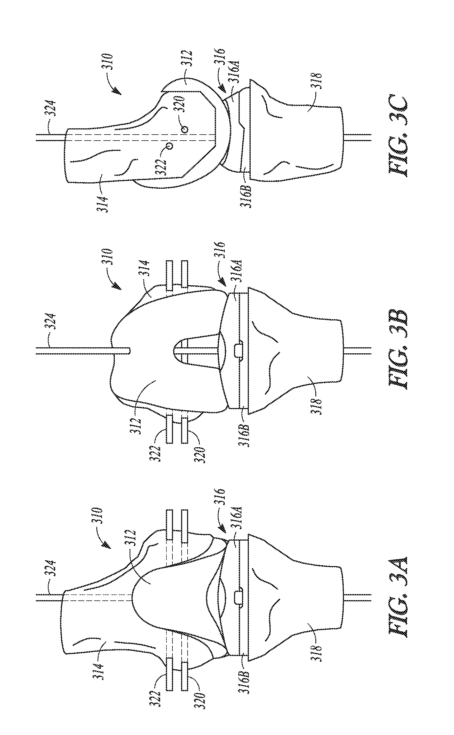
[0035] FIG. 3A is a frontal or coronal plane view of a knee joint with an implanted knee prosthesis according to an example of the present application.
[0036] FIG. 3B is a coronal view of the knee joint and knee prosthesis of FIG. 3A in 90 degrees flexion according to an example of the present application.
[0037] FIG. 3C is a side or sagittal plane view of the knee joint and knee prosthesis of FIGS. 3A and 3B in full extension according to an example of the present application.
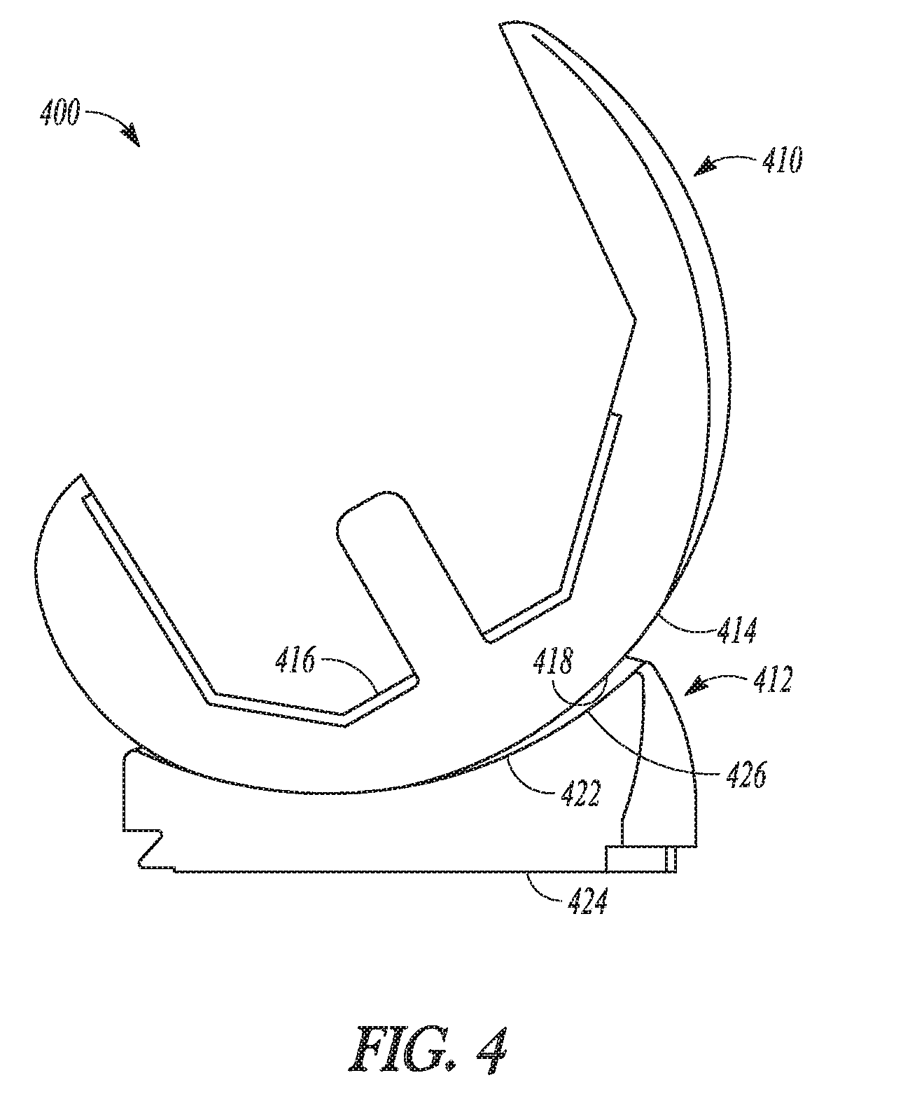
[0038] FIG. 4 shows a femoral component assembled with a bearing component in accordance with an example of the present application.
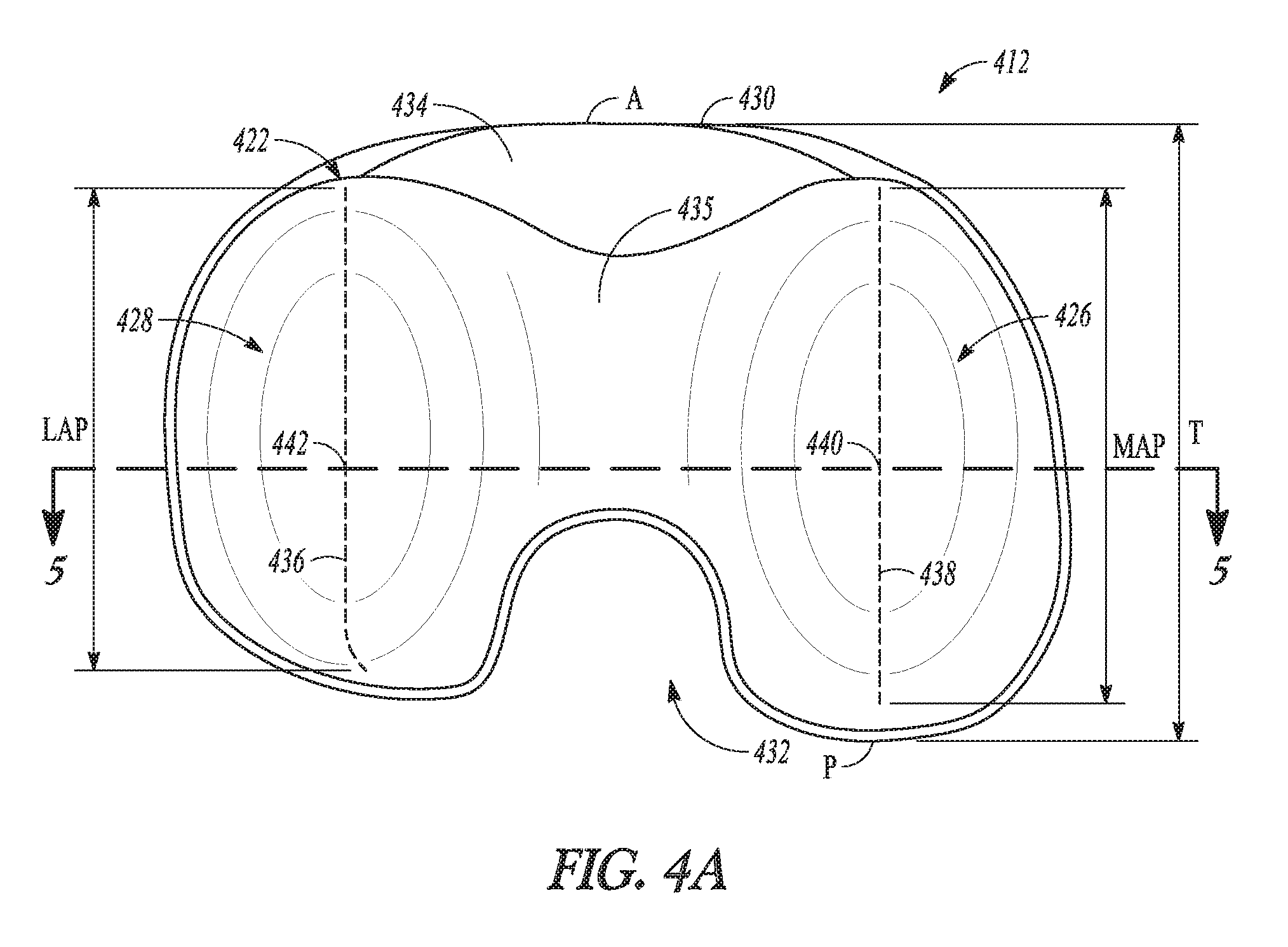
[0039] FIG. 4A shows a plan view of a proximal surface of the bearing component of FIG. 4 in accordance with an example of the present application.
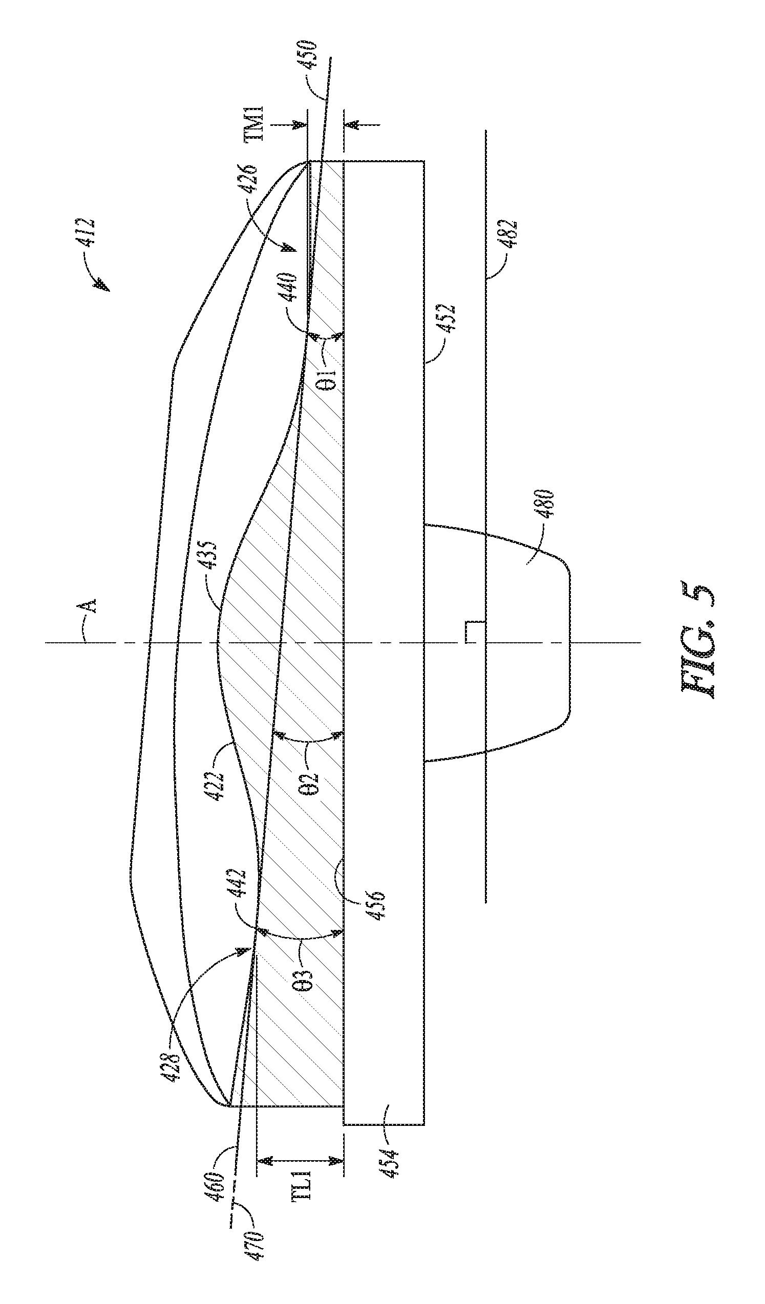
[0040] FIG. 5 shows a cross-sectional view of the bearing component of FIGS. 4 and 4A taken along a coronal plane and showing an inclination of the articular surfaces of the bearing component in accordance with an example of the present application.
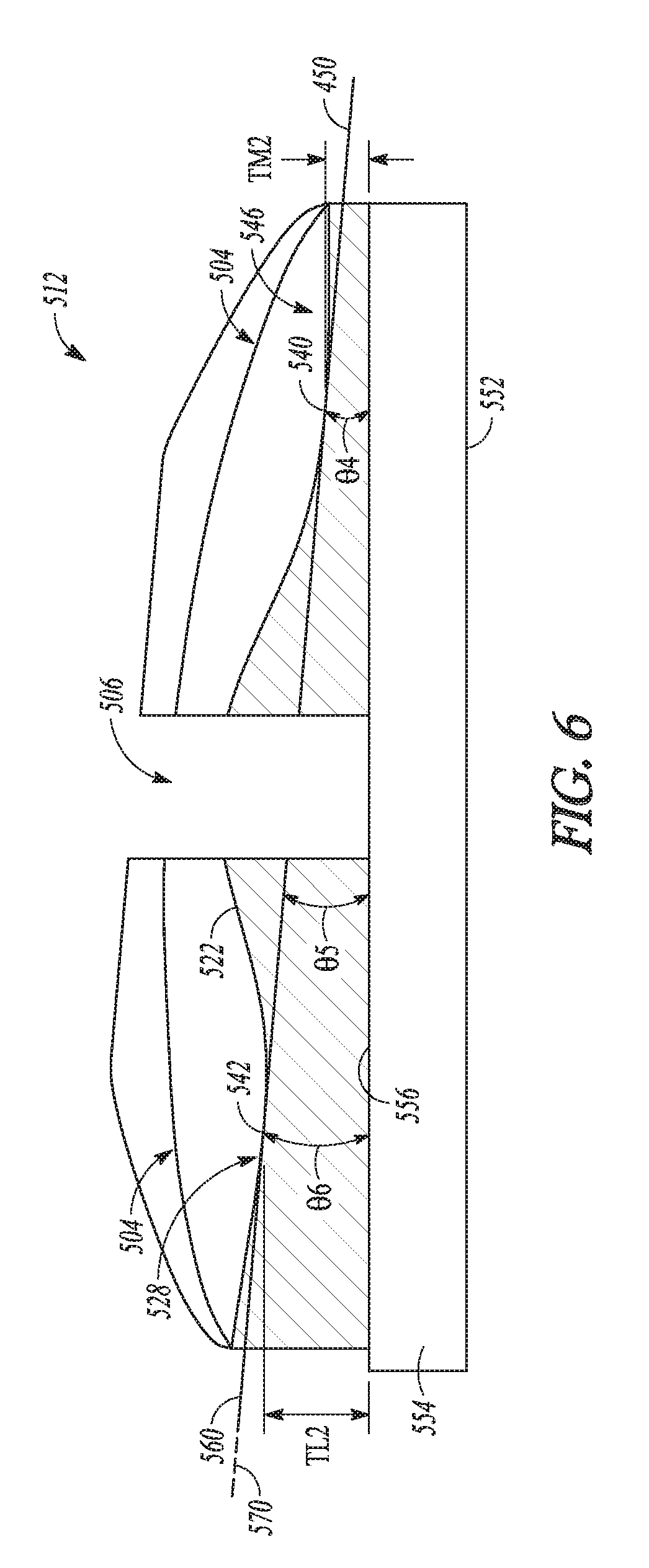
[0041] FIG. 6 shows another example of a bearing component in a cross-section taken along a coronal plane showing the inclination of the articular surfaces of the bearing component in accordance with an example of the present application.
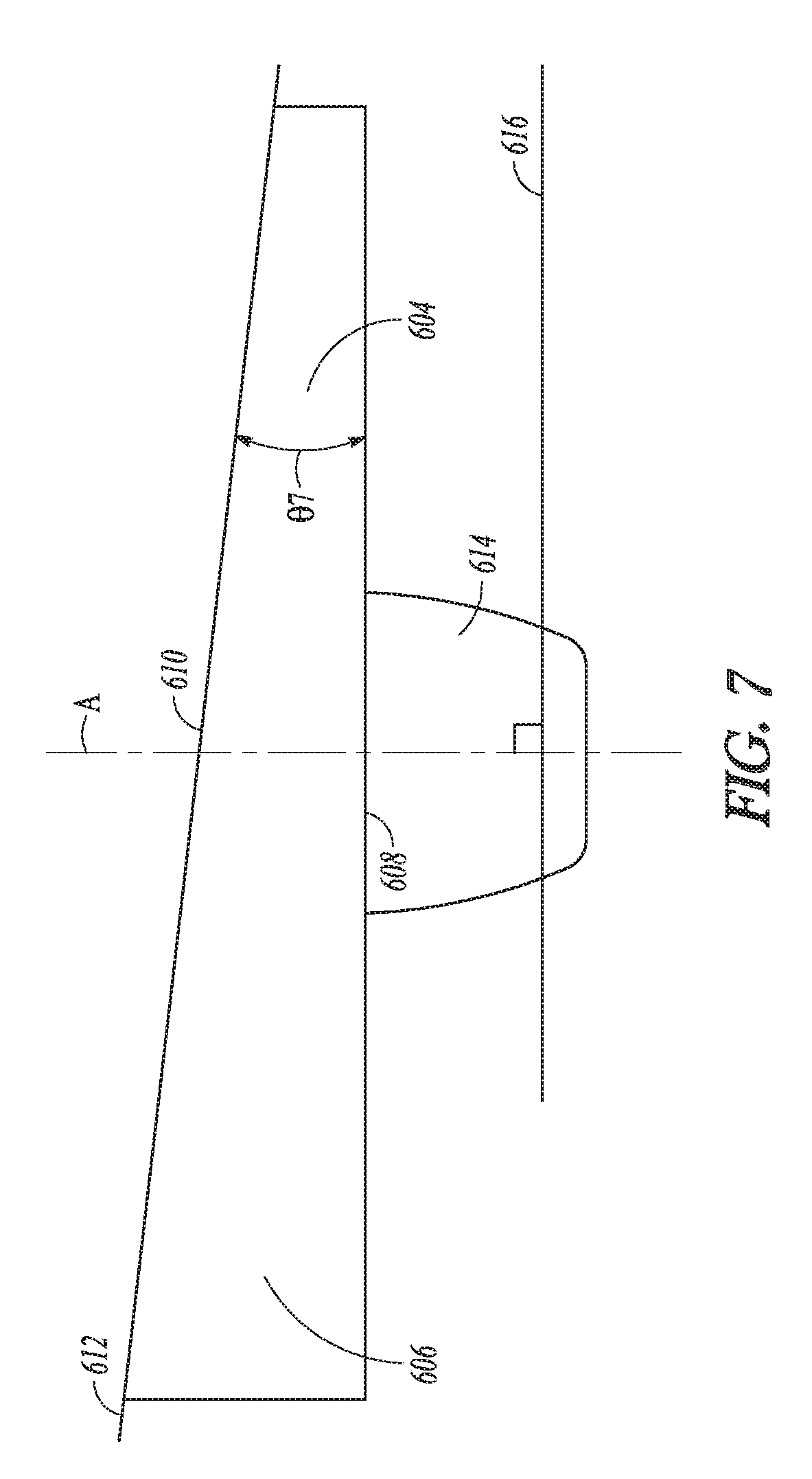
[0042] FIG. 7 shows a tibial baseplate shown in cross-section in a coronal plane, the proximal surface has an inclination relative to a distal surface of the tibial baseplate in accordance with an example of the present application.
DETAILED DESCRIPTION
[0043] The present disclosure relates to implantable prostheses, trial instruments, and systems that can be used in knee replacement procedures such as total knee arthroplasty (TKA), and other suitable knee replacement procedures such as a partial knee arthroplasty like a bicompartmental knee arthroplasty wherein both medial and lateral tibiofemoral compartments are being replaced. TKA surgery, for example, can involve the implantation of prosthetic components meant to restore the functionality provided by a natural knee. Typical TKA components include a tibial baseplate, a femoral component, and a bearing component disposed between the tibial baseplate and the femoral component. In a bicompartmental knee arthroplasty, both a medial condyle and a lateral condyle of the femur and the tibia are resected to remove the medial articular surface and the lateral articular surface. Similar to a unicompartmental knee arthroplasty procedure, the bicompartmental knee arthroplasty maintains some portions of the knee in an un-resected state such as the intercondylar eminence or patellofemoral compartment. Bicompartmental knee arthroplasty can use the tibial baseplate, femoral component and the bearing component similar to TKA components but with modified construction.
[0044] The present disclosure provides knee prostheses and systems that include bearing components and/or tibial baseplates in which the components are configured to provide joint inclination to the TKA, bicompartmental knee arthroplasty, etc.
[0045] Before knee replacement surgery, a surgeon can preoperatively assess a patient's native joint line using any suitable method, such as, for example, by imaging technology (e.g., computed tomography (CT scan), x-ray, magnetic resonance imaging (MRI), etc.). In order to prepare the tibia and femur for receipt of a knee prostheses including components of the present disclosure, any suitable methods or apparatuses for implantation of the knee joint prosthesis components can be used. During this process the surgeon can identify a patient's native joint line (indicated as 122 in FIG. 1) using the results from the digital imagining technology.
[0046] Several different approaches for a TKA procedure exist including a first technique that utilizes mechanical alignment of the knee prostheses and a second technique that utilizes kinematic alignment of the knee prostheses. The present methods and/or apparatuses of this disclosure can be useable with either the former technique or the latter technique. If used with the kinematic technique, the present apparatuses can be configured to take into account the relatively larger degree of native or natural varus joint inclination that a patient may present with and that may further result from that technique for the tibial baseplate, bearing component, and femoral component.
[0047] Mechanical alignment considers a three-dimensional (3D) alignment of the limb and the knee, including: aligning the femoral component perpendicular to the mechanical axis of the femur in the coronal plane by adjusting its varus-valgus alignment; aligning the tibial component perpendicular to the mechanical axis of the tibia in the coronal plane by adjusting its varus-valgus alignment; and, allowing the other five degrees of freedom to be adjusted by the surgeon's surgical technique. Namely, the considerations include adjusting the anterior-posterior, medial-lateral, proximal-distal, internal-external rotation, and flexion-extension axes of the femoral component. The considerations for the tibial component placement include a surgeon adjusting the anterior-posterior, medial-lateral, proximal-distal, internal-external rotation, and posterior slope. Kinematic alignment considers these same six degrees of freedom with respect to the knee, however the varus-valgus alignment of the femoral and tibial components may not be set perpendicular to the mechanical axes of the patient's anatomy. The intention of kinematic alignment is the restoration of the normal 3D orientation of three axes that describe normal knee kinematics. The primary goals of a kinematically aligned TKA are (1) positioning the femoral and tibial components of a knee prosthesis such that the angles and levels of the distal and posterior femoral and tibial joint lines are restored to the patient's natural joint line (which may include the varus-valgus angle of the femoral and tibial components not being perpendicular to their respective mechanical axes), (2) restoration of the patient's natural or constitutional alignment prior to the patient having developed osteoarthritis, and (3) restoration of the patient's natural soft tissue laxity and envelope. FIGS. 1 and 2 illustrate several features of knee joint structures and orientations that are used in mechanical and kinematic alignment.
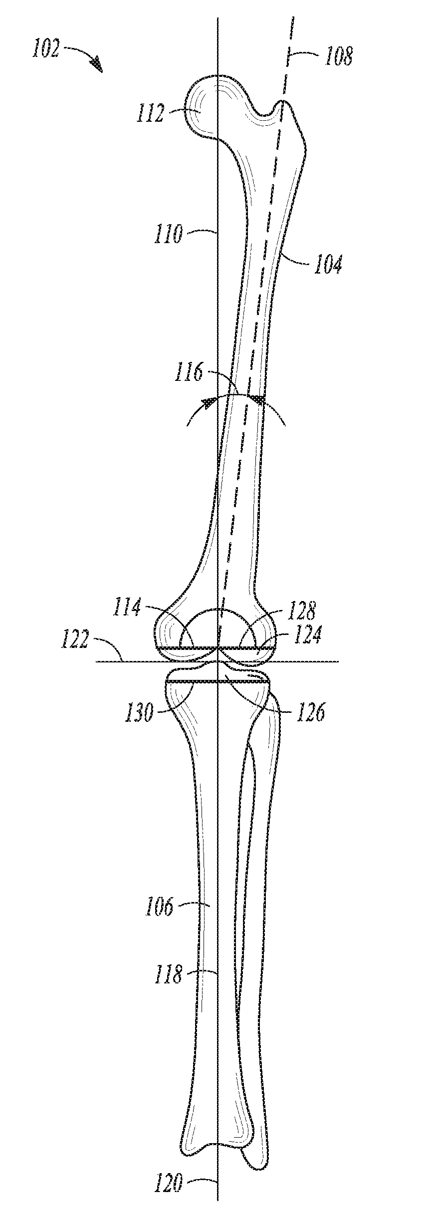
[0048] In FIG. 1, a frontal view of a lower limb 102, including a femur 104 and a tibia 106, is shown to illustrate various lower limb axes. The femur 104 has an anatomic axis 108 that coincides generally with its intramedullary canal. The femur 104 also has a mechanical axis 110, or load axis, running from the center of a femoral head 112 to the center of a knee joint 114. The angle 116 extending between these two axes varies among the patient population, but is generally on the order of between 5-7 degrees, inclusive. Like the femur 104, the tibia 106 also has an anatomic axis coinciding generally with its intramedullary canal. The mechanical axis 118 of the tibia 106 runs from the center of the knee joint 114 to the center of an ankle region 120 and is generally collinear with its anatomic axis.
[0049] A patient's native joint line 122, about which the knee joint 114 flexes and extends, has an approximate degree of inclination to a line through medial and lateral femoral condyles 124 and to a tibial plateau 126. Although illustrated as perpendicular in FIG. 1, the joint line 122 can extend at a varus or valgus angle (usually of a few degrees) relative to the mechanical axes 110 and 118 of the femur 104 and tibia 106, respectively and thereby not be perpendicular to these noted mechanical axes of the femur and tibia. Normally, during a mechanically aligned total knee replacement procedure, portions of a distal end of the femur 104 and/or a proximal end of the tibia 106 are resected to be perpendicular to the mechanical axes 110 of the femur and 118 of the tibia. Thereby placing the patient's joint line 122 approximately perpendicular to the femoral mechanical axis 110 and the tibial mechanical axis 118. The resected cut planes of the femur and tibia are indicated at 128 and 130, respectively. During a kinematically aligned total knee replacement procedure, portions of a distal end of the femur 104 and/or a proximal end of the tibia 106 are resected to be not perpendicular to the mechanical axes 110 of the femur and 118 of the tibia. In this kinematically aligned total knee procedure, the resected cut planes of the femur and tibia, 128 and 130 respectively, are resected to be parallel to the patient's normal joint line, 122, which may have some degree of inclination, or angle.
[0050] With the systems and apparatuses of the present application the proximal end of the tibia 106 need not be resected to be parallel or approximately parallel to the match the patient's native joint line 122. Therefore, with the present systems and apparatuses, line 130 need not be parallel to joint line 122. Thus, the present methods and apparatuses can reduce surgical time as time consuming matching of the tibial resection 130 to the joint line 122 is not necessary. Rather, with the present systems and apparatuses, a resection to form line 130 can simply be performed to mechanically match the tibial axis 118 and the bearing component and/or the tibial baseplate can then be selected to add a desired joint inclination for the implant assembly. This joint inclination can substantially match the patient's native joint line (e.g., joint line 122). It is also contemplated that differing medial and lateral soft-tissue tensions can be provided for the knee via the configuration of bearing component and/or the tibial baseplate that provides for the joint inclination.
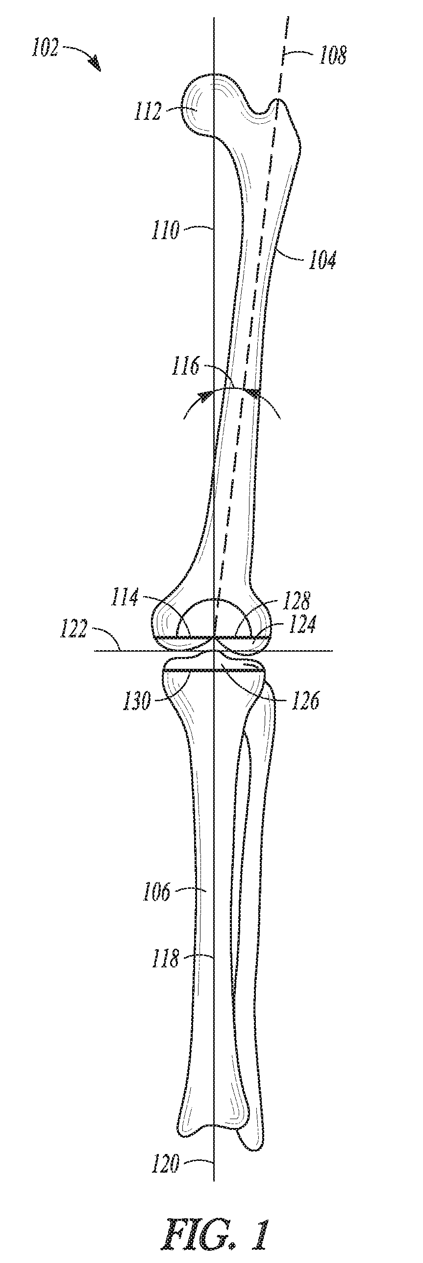
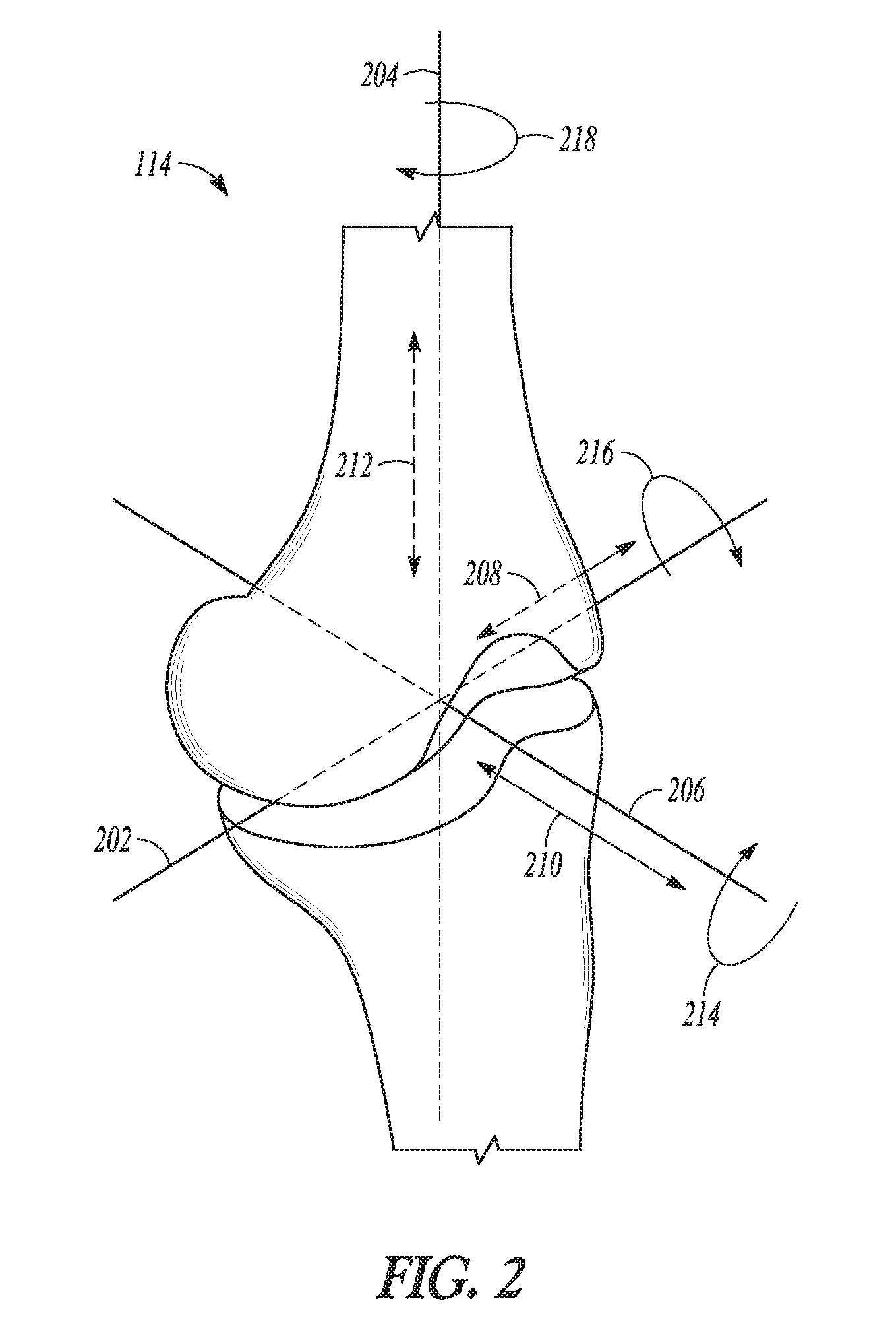
[0051] FIG. 2 illustrates a closer view of the knee joint 114 and its coordinate system, in which a medial-lateral axis 202 corresponds approximately to the joint line 122 (FIG. 1), a proximal-distal axis 204 corresponds approximately to the mechanical axes 110 and 118 (FIG. 1) or approximately to the anatomic axis 108 (FIG. 1). An anterior-posterior axis 206 is approximately normal to the other two axes. Position along each of these axes can be depicted by arrows, which can represent the medial-lateral 208, anterior-posterior 210, and proximal-distal 212 positioning of inserted prosthesis components. Rotation about each of these axes can also be depicted by arrows. Rotation about the proximal-distal axis 204 can correspond anatomically to external rotation of a femoral component, while rotation about the anterior-posterior axis 206 and medial-lateral axis 202 can correspond to varus-valgus angle and extension plane slope of a component, respectively.
[0052] As discussed above, kinematic alignment techniques matched the proximal tibial cut 130 (FIG. 1) to the joint line 122 (FIG. 1) and mechanical alignment techniques matched the proximal tibial cut 130 to perpendicular to the tibial axis 118 (FIG. 1). The position and angle of the proximal tibial cut 130 (FIG. 1) can affect one or more of a varus-valgus angle 214, extension plane angle 216, external rotation 218, or joint extension gap. Similarly, prior techniques matched the distal femoral cut 128 (FIG. 1) to be perpendicular to the mechanical axis 110 (FIG. 1) or perpendicular to the anatomic axis 108. The position and angle of the distal femoral cut 128 (FIG. 1) can affect one or more of the extension gap, the varus-valgus angle 214, or the extension plane angle 216. However, the present systems and apparatuses simplify the technique and reduce the need for consideration of such angles and/or gaps. This is because a surgeon can now use the present bearings or tibial baseplates to add an appropriate amount of varus-valgus angle 214 to adjust to the patient's native joint line or to tension the knee differently medially compared to laterally.
[0053] The kinematically aligned TKA can include a determination of three kinematic axes as illustrated and described in reference to FIGS. 3A-3C. FIGS. 3A-3C show various views of a knee prosthesis 310 implanted on a knee joint and illustrate the three kinematic axes of the knee joint in a kinematically aligned TKA. The knee prosthesis 310 includes a femoral component 312 implanted on a femur 314 and a tibial component 316 implanted on a tibia 318. The tibial component 316 can include both a bearing component 316a (in FIG. 3A) and a tibial baseplate 316b (in FIG. 3A). A first kinematic axis 320 can be a transverse axis in the femur 314 about which the tibia 318 flexes and extends. The first kinematic axis 320 can be determined by projecting the lateral and medial femoral condyles of the femur 314 onto one another and fitting circles of equal radii over each other. The first kinematic axis 320 passes through a center of the circles. A second kinematic axis 322 can be a second transverse axis, parallel to the first kinematic axis 320, about which a patella of the knee joint flexes and extends. The second kinematic axis 322 can be located anterior and proximal to the first kinematic axis 320. A third kinematic axis 324 is an axis perpendicular to the first 320 and second 322 axes about which the tibia 318 internally and externally rotates on the femur 314.
[0054] The femoral component, such as 312 (in FIG. 3A), of the present application can be any suitable femoral component known or contemplated in the art. The femoral component can comprise an anterior surface with patella track and two femoral condyles, for example. By way of example, the construction of the femoral component is variously described in U.S. Pat. Nos. 8,858,643, 9,072,607, 8,690,954, 8,764,838, 8,932,365 and United States Application Publication No. 2012/0323336, the disclosures of which are incorporated by reference in their entirety.
[0055] Some exemplary surgical procedures and associated techniques and surgical instruments that may be used during method of implantation of prostheses of the present application are disclosed in "Zimmer LPS-Flex Fixed Bearing Knee, Surgical Technique," "NEXGEN COMPLETE KNEE SOLUTION, Surgical Technique for the CR-Flex Fixed Bearing Knee", "Zimmer NexGen Complete Knee Solution Extramedullary/Intramedullary Tibial Resector, Surgical Technique" (collectively the "Zimmer Surgical Techniques"), and "Vanguard.RTM. ID Total Knee Surgical Technique" the entireties of which are hereby expressly incorporated herein by reference. Additional surgical procedures are disclosed in application Ser. No. 14/809,810, entitled "INSTRUMENTS AND METHODS IN PERFORMING KINEMATICALLY-ALIGNED TOTAL KNEE ARTHROPLASTY" filed Jul. 27, 2015, application Ser. No. 13/819,528, entitled "FEMORAL PROSTHESIS WITH MEDIALIZED PATELLAR GROOVE", filed Sep. 9, 2011, and application Ser. No. 12/695,804, entitled "APPARATUS AND METHOD FOR THE EXTRAMEDULLARY LOCATION OF THE MECHANICAL AXIS OF A FEMUR", filed Jan. 28, 2011 and the entire disclosures of which are incorporated herein by reference and are co-owned by the Applicant.
[0056] In application Ser. No. 13/819,528, a methodology is discussed whereby the mechanical axis and the anatomic axis are identified by the surgeon. Knowledge of these axes can be used in planning resections, implant orientation, etc. It is recognized that the mechanical axis extends from the center of femoral head to the center of the knee joint and is the weight bearing axis of femur. The anatomical axis extends along the longitudinal axis of shaft of femur. A surgeon may find anatomical axis by, e.g., obtaining pre-operative images (such as CT scans, magnetic resonance imagining, X-rays or the like) and estimating the longitudinal axis of the shaft of femur based on sight and appearance. During a surgical procedure, a surgeon may find anatomical axis by inserting an intramedullary rod into the intramedullary canal of femur. Once the rod is so inserted, the axis of the rod is substantially coincident with the axis of femur. To find mechanical axis, a surgeon may again use preoperative images to estimate the location of axis by sight. Alternatively, the surgeon may use a rod-based system in conjunction with manipulation of the leg to find axis. Additionally, surgeons can template the proximal tibial angle using digital x-rays or other imaging technology to determine the axes and other anatomy of the knee joint as previously described with regard to FIGS. 1 and 2. Furthermore, surgeons can measure the angle of one or both of the tibia and femur removed upon resection such as with a calipers or another instrument and use this angle to derive the axes and other anatomy of the knee joint as previously described with regard to FIGS. 1 and 2.
[0057] According to some examples, the present application provides the basis for a prosthetic trial system having interchangeable components. The prosthetic trial system can include a plurality of trial tibial baseplates, each of which are able to seat on one or more portions of the tibia. These plurality of baseplates can be differently configured (e.g., provided with different thicknesses, sizes, and/or inclinations relative to one another). In some examples, some or all of the trial tibial baseplates can be configured with no inclination. This can be because the thickness of a medial portion of each tibial baseplate can be substantially the same the thickness of a lateral portion. In other examples, some or all of the trial tibial baseplates can be configured with different inclinations (e.g., between 0.5.degree. and 9.degree., inclusive) that can result from the medial portion having a different thickness than the thickness of the lateral portion. These inclinations can allow the system to achieve a plurality of different joint inclinations when coupled to a standard hearing component having no inclination or alternatively could allow a surgeon to add or lessen an amount of tension in the medial and/or lateral compartments of a knee joint fitted with a prosthesis.
[0058] The prosthetic trial system can additionally or alternatively also include a plurality of trial bearing components, which can be placed between a femoral component and one of the trial tibial baseplates. Each of the plurality of trial bearing components can provide for relatively different joint inclinations (e.g., with an acute angle between 0.5.degree. and 9.degree., inclusive) for the system. The different joint inclinations can be achieved by varying the thicknesses of the medial and lateral portions of the trial tibial baseplate relative to one another and by having an inclination for the articular surfaces of both the lateral and medial portions. Accordingly, a surgeon can optimally select the configuration of the tibial component and/or the bearing component so as to obtain the desired joint inclination. Such desired joint inclination can be one that best matches the natural joint line (e.g., joint line 122 of FIG. 1), for example or alternatively could allow a surgeon to add or lessen an amount of tension in the medial and/or lateral compartments of a knee joint fitted with a prosthesis.
[0059] In view of the above systems, the trialing process can include recreation by the surgeon of the natural joint line of the patient by selecting independent bearing components (e.g., a separate medial component and a separate lateral component) that contain both appropriate thicknesses and inclinations. In other examples, the trialing process can include tensioning of the joint a desired amount and selecting the independent bearing components that contain both appropriate thicknesses and inclinations to match the tensioning of the joint. In yet other examples, the trialing process can include selecting the independent bearing components that contain both appropriate thicknesses and inclinations to achieve a desired tension medially v. laterally. In yet further examples, a monolithic trial bearing component and/or a trial tibial baseplate having a desired inclination can be utilized in alternative to the independent bearing component discussed above.
[0060] FIG. 4 shows an assembly 400 of a femoral component 410 with a bearing component 412 for a TKA according to one example. As shown in FIG. 4, a femoral component 410 can include articular surfaces 414 and proximal surfaces 416. As shown in FIG. 4, the articular surfaces 414 can include a medial condyle 418 and a lateral condyle (not shown in FIG. 4). The bearing component 412 can include articular surfaces 422 and a distal surface 424. The articular surfaces 422 can include a medial compartment 426 (also referred to as a medial portion or medial part herein) and a lateral compartment 428 (shown in FIG. 4A, also referred to as a lateral portion or lateral part herein).
[0061] The bearing component 412 can be constructed for use as a meniscal bearing component of a TKA, and therefore, can be constructed of suitable biocompatible materials such as high density polyethylene or the like.
[0062] As shown in the example of FIG, 4, the bearing component 412 can be compatible with and configured for operable use with the femoral component 410. In particular, the articular surfaces 422 of the bearing component 412 can be configured to receive the articular surfaces 414 of the femoral component 410 thereon and can be configured with some conformity to allow for movement of the femoral component 410 relative thereto in a manner that simulates the kinematics of a natural knee (e.g., allow for rollback of the femoral component 410 in flexion including anterior-posterior translation).
[0063] The proximal surfaces 416 of the femoral component 410 can be configured to receive and couple to resected distal surfaces of the femur. The articular surfaces 414 can have conformity with the articular surfaces 422 to allow for the articulation as described above. As shown in FIG. 4A, the medial compartment 426 and the lateral compartment 428 (shown in FIG. 4A) can be configured for articulation with the medial condyle 418 and the lateral condyle (not shown in FIG, 4) of the femoral component 410, respectively. The articular surfaces 422 can be arranged opposing the distal surface 424. The distal surface 424 can be shaped to interface with a proximal surface of a tibial baseplate (subsequently shown in the examples of FIGS. 5-7) that can be affixed or otherwise mounted to a resected proximal surface of the tibia (not shown).
[0064] FIG. 4A shows a plan view of a proximal portion of the bearing component 412. FIG. 4A shows an example where the bearing component 412 is monolithic (single piece) in construction having both the medial compartment 426 and the lateral compartment 428. However, as previously described and subsequently illustrated, bearing components of multi-piece construction (two-pieces comprising a medial portion and a lateral portion, three-piece, etc.) are also contemplated. As shown in FIG. 4A, the bearing component 412 can include the articular surfaces 422, a periphery 430, a posterior cutout 432 and an anterior relief space 434. The articular surfaces 422 can include the medial compartment 426, the lateral compartment 428 and an intercondylar eminence 435.
[0065] As previously described, the articular surfaces 422 can be contacted by the condyles (not shown) of a femoral component when operably assembled in the knee. The condyles of the femoral component can contact the medial and lateral compartments 426, 428. More particularly, the medial compartment 426 and the lateral compartment 428 can be configured (e.g. are concave so as to he dish shaped) for articulation with the medial condyle and the lateral condyle of the femoral component, respectively (as shown in FIG. 4). The articular surfaces 422 (sometimes referred to as simply a proximal surface or proximal surfaces herein) can be generally opposed by a distal surface of the bearing component 412. The periphery 430 can comprise sidewalls connecting with the distal surface and the articular surface 422. The medial compartment 426 can differ in configuration from the lateral compartment 428 as will be explained in further detail subsequently. For example, the medial compartment 426 can have a different thickness, in-plan size and shape relative to the lateral compartment 428. In some examples, the anterior-posterior curvature of the lateral compartment 428 can differ from that of the medial compartment 426. However, as is shown in subsequent FIGURES an inclination of the medial compartment 426 along at least a portion of its articular track can be substantially the same as an inclination of the lateral compartment 428 along at least a portion of its articular track.
[0066] As shown in the example of FIG. 4A, the lateral compartment 428 can have a lateral articular track 436 having a lateral anterior-posterior extent L.sub.AP. The lateral articular track 436 can comprise a plurality of distal-most points along the articular surface 422 of the lateral compartment 428 that are contacted by the lateral femoral condyle during rollback of the femoral component. Similarly, the medial compartment 426 can have a medial articular track 438 having a medial anterior-posterior extent MAP that differs from the lateral anterior-posterior extent L.sub.AP. The medial articular track 438 can comprise a plurality of distal-most points along the articular surface 422 of the medial compartment 426 that are contacted by the medial femoral condyle during rollback of the femoral component.
[0067] For convenience, the present discussion refers to points, tracks or lines of contact between the bearing component 412 and the femoral component along the articular tracks 436, 438. However, it is of course appreciated that each potential point or line of contact (i.e., any of the points along one of the articular tracks 436, 438) is not truly a point or line, but rather an area of contact. These areas of contact may be relatively larger or smaller depending on various factors, such as prosthesis materials, the amount of pressure applied at the interface between the bearing component 412 and the femoral component, relative shapes of the bearing component 412 relative to the femoral component, and the like. Moreover, it is appreciated that some of the factors affecting the size of the contact area may change dynamically during prosthesis use, such as the amount of applied pressure at the femoral/tibial interface during walking, climbing stairs or crouching, for example. For purposes of the present discussion, a contact point may be taken as the point at the geometric center of the area of contact. The geometric center, in turn, refers to the intersection of all straight lines that divide a given area into two parts of equal moment about each respective line. Stated another way, a geometric center may be said to be the average (i.e., arithmetic mean) of all points of the given area. Similarly, a line or track is the central line of contact passing through and bisecting an elongate area of contact.
[0068] Both the medial compartment 426 and the lateral compartment 428 can include dwell points 440 and 442. The dwell points 440 and 442 can comprise distal-most points along the medial articular track 438 and the lateral articular track 436, respectively. The dwell points can comprise the points on the articular surface 422 where the inclination(s) of the bearing component 412 are measured according to some examples. Although the dwell points 440 and 442 are shown as being disposed a relatively similar anterior-posterior location in the example of FIG. 4A, in other examples the anterior-posterior location (as indicated by distance T measured from anterior point A to posterior point P) of the dwell point 440 can differ from that of the dwell point 442.
[0069] According to some examples, the articular tracks 436, 438 can comprise the points on the articular surface 422 where the inclination(s) of the bearing component 412 are measured. In further examples, the dwell points 440 and 442 can comprise the points on the articular surface 422 where the inclination(s) of the bearing component 412 are measured. Alternatively, in yet further examples, the inclination(s) can he measured relative to a long axis of the tibia (approximated by the center of the tibia plateau) as will explained in further detail subsequently.
[0070] As shown in FIG. 4A, the posterior cutout 432 is sized and positioned to accommodate a posterior cruciate ligament upon implantation of the bearing component 412. The intercondylar eminence 435 can comprise an intercondylar ridge of the articular surface 422 that can be disposed between the medial and lateral compartments 426, 428. The intercondylar eminence 435 can extend generally anterior-posterior from the posterior cutout 432 to the anterior relief space 434. Thus, the intercondylar ridge defined by the intercondylar eminence 435 can be disposed between the medial and lateral dished medial and lateral compartments 426, 428 and occupies the available anterior-posterior space therebetween.
[0071] FIG. 5 is a highly schematic cross-section of the bearing component 412 along line 5-5 of FIG. 4A, the line 5-5 corresponding to a coronal plane of the bearing component 412. As previously discussed with respect to FIG. 4A, the bearing component 412 of FIG. 5 has a monolithic construction and includes the medial compartment 426, the lateral compartment 428 and the intercondylar eminence 435.
[0072] As shown in FIG. 5, the medial compartment 426 can have a first inclination 450 (as indicated by a tangent line) as measured at the dwell point 440 of the medial compartment 426 relative to the resected tibial surface (approximated by a distal surface 452 of a tibial baseplate 454). Similarly, the lateral compartment 428 can have a second inclination 460 (as indicated by a tangent line) as measured at the dwell point 442 of the lateral compartment 428 relative to the resected tibial surface (approximated by the distal surface 452 of the tibial baseplate 454). The medial compartment 426 can have a thickness TM1 at the point where the first inclination 450 is measured. The thickness TM1 can differ from a corresponding thickness TL1 of the lateral compartment 428. The thickness TL1 of the lateral compartment 428 can be determined at the point where the second inclination 460 is measured. The first inclination 450 can form an acute angle .theta.2 with one or more of the resected tibial surface, the distal surface 452 and a proximal surface 456 of the tibial baseplate 454. The acute angle .theta.1 can be between 1.degree. and 9.degree., inclusive according to one example. Similarly, the second inclination 460 can form an acute angle .theta.2 with one or more of the resected tibial surface, the distal surface 452 and a proximal surface 456 of the tibial baseplate 454. The acute angle .theta.2 can be between 1.degree. and 9.degree., inclusive according to one example. An overall inclination 470 can form an acute angle .theta.3 that can be between 1.degree. and 9.degree., inclusive according to one example.
[0073] As shown in the example of FIG. 5, the first inclination 450 can be substantially the same as the second inclination 460 to provide the overall inclination 470 (indicated by dashed line) of the articular surfaces 422 of the bearing component 412 relative to one or more of the proximal surface 456, the distal surface 452, and the resected tibial surface. Although the example of FIG. 5 describes the inclinations as being measured at the dwell points, the inclinations can be measured at any point on the articular track and/or relative to other features (e.g., the long axis of the tibia) according to further examples. As discussed above the inclination of the articular surface 422 at the medial compartment 426 and/or the lateral compartment 428 can also be determined by a tangent line that passes through the articular track for that compartment such as at the dwell point. The angle of the tangent line relative to the resected tibial surface in the coronal plane can approximate the inclination. According to a further example, inclination of the articular surface 422 at the medial compartment 426 and/or the lateral compartment 428 can also be determined relative to the long axis of the tibia. The long axis of the tibia can be approximated by a longitudinal axis A of a distal feature 480 such as a keel of the tibial baseplate 454. The distal feature 480 is configured to seat in the diaphysis and/or metaphysis, which corresponds to the long axis of the tibia. Thus, the longitudinal axis A of the distal feature 480 can approximate the long axis. The inclination(s) can be measured from a line 482 that intersects the longitudinal axis A in a transverse manner.
[0074] Additionally, the inclination(s) may be present for only portion of the anterior-posterior extent of the medial and/or lateral articular tracks (refer to discussion above with regard to FIG. 4A) according to some examples. According to further examples, the inclinations can be present for the entire anterior-posterior extent of the medial and/or lateral articular tracks.
[0075] As discussed above, the present apparatuses, systems and techniques can 1) allow a surgeon to easily add joint inclination if the proximal cut surface of the tibia is cut perpendicular to the long axis of the tibia or alternatively 2) also allow for no point loading of the femur on the bearing because of the inclination (versus potential for point loading by providing for overall joint inclination with thicker medial or lateral sides that lack varus-valgus inclination for either portion).
[0076] FIG. 6 shows another example of a bearing component 512 that comprises first and second bearing elements 502 and 504 that are separate from on another by a gap 506. The first bearing element 502 can be configured to comprise a medial compartment 526 having a similar or identical construction to that of the medial compartment 426 previously described. Similarly, the second bearing element 504 can be configured to comprise a lateral compartment 528 having a similar or identical construction to that of the lateral compartment 428 previously described.
[0077] As shown in FIG. 6, the medial compartment 526 can have a first inclination 550 as measured at the dwell point 540 of the medial compartment 526 relative to the resected tibial surface (approximated by a distal surface 552 of a tibial baseplate 554). Similarly, the lateral compartment 528 can have a second inclination 560 as measured at the dwell point 542 of the lateral compartment 528 relative to the resected tibial surface (approximated by the distal surface 552 of the tibial baseplate 554). The medial compartment 526 can have a thickness TM2 at the point where the first inclination 550 is measured. The thickness TM2 can differ from a corresponding thickness TL2 of the lateral compartment 528. The thickness TL2 of the lateral compartment 528 can be determined at the point where the second inclination 560 is measured.
[0078] The first inclination 550 can form an acute angle .theta.4 with one or more of the resected tibial surface, the distal surface 552 and a proximal surface 556 of the tibial baseplate 554. The acute angle .theta.4 can be between 1.degree. and 9.degree., inclusive, according to one example. Similarly, the second inclination 560 can form an acute angle .theta.5 with one or more of the resected tibial surface, the distal surface 552 and the proximal surface 556 of the tibial baseplate 554. The acute angle .theta.5 can be between 1.degree. and 9.degree., inclusive, according to one example
[0079] As shown in the example of FIG. 6, the first inclination 550 can be substantially the same as the second inclination 560 to provide an overall inclination 570 (indicated by dashed line) of the articular surfaces 522 of the bearing component 412 relative to one or more of the resected tibial surface, the distal surface 552 and the proximal surface 556. The overall inclination 570 can form an acute angle .theta.6 that can be between 1.degree. and 9.degree., inclusive, according to one example. Although the example of FIG. 6 describes the inclinations as being measured at the dwell points, the inclinations can be measured at any point on the articular track, in other manners and/or relative to other features (e.g., the long axis of the tibia) in the manner previously discussed with reference to FIG. 5.
[0080] FIG. 7 shows an alternative for providing an inclination for an implant assembly. In FIG. 7, a tibial baseplate 602 is shown. The tibial baseplate 602 has a medial portion 604, a lateral portion 606, a distal surface 608 and a proximal surface 610.
[0081] The distal surface 608 can be configured to interface with and mount on a resected surface of the tibia (not shown). The proximal surface 610 can be spaced from the distal surface 608 and can be configured to couple with a bearing component (not shown). The bearing component can be of conventional design and need not be inclined in the manner of bearing components of FIGS. 4-6.
[0082] The tibial baseplate 602 can be wedge shaped such that the proximal surface 610 is oriented at a desired inclination 612 (indicated by line) relative to the resected surface of the tibia (not shown but corresponding to the distal surface 608). The inclination 612 can form an acute angle .theta.7 with the distal surface 608. More particularly, the medial portion 604 can have a thickness along its medial-lateral extent at differs from a thickness of the lateral portion 606 along its medial-lateral extent.
[0083] The tibial baseplate 602 can include a distal feature 614 such as a keel similar to the one previously described in reference to FIG. 5. The distal feature 614 can couple to the distal surface 608 and can extend therefrom. According to one example, the inclination 612 can also be determined relative to the long axis of the tibia that can be approximated by a longitudinal axis A of the distal feature 614. The distal feature 614 is configured to seat in the diaphysis and/or intramedullary canal, which corresponds to the long axis of the tibia. Thus, the longitudinal axis A of the distal feature 614 can approximate the long axis. The inclination 612 can be measured from a line 616 that intersects the longitudinal axis A in a transverse manner. It can also be contemplated that the tibial component 602 could be similarly separated into medial and lateral components such as with a bicompartmental procedure whereby a gap separates the two. This gap, for example, can be comprised of bony anatomy, high density polyethylene, or other contemplated materials or patient anatomy.
[0084] The embodiments of the bearing components and tibial trays shown and described herein illustrate components for either left or a right knee prosthesis. Right and left knee prosthesis configuration are mirror images of one another about a sagittal plane. Thus, it will be appreciated that the aspects of the prosthesis described herein are equally applicable to a left or a right knee configuration.
[0085] As used herein, "proximal" refers to a direction generally toward the head of a patient, and "distal" refers to the opposite direction of proximal, i.e., away from the head of a patient. As used herein, the terms "anterior" and "posterior" should be given their generally understood anatomical interpretation. Thus, "posterior" refers to a rear of the patient, e.g., a back of the knee. Similarly, "anterior" refers to a front of the patient, e.g., a front of the knee. Thus, "posterior" refers to the opposite direction of "anterior." Similarly, the terms "medial" and "lateral" should be given their generally understood anatomical interpretation. "Medial" refers to the inner part of the knee prosthesis (when in the implanted orientation) and "lateral" refers to the outer part. "Medial" refers to the opposite direction of "lateral." "Varus" is defined as relating to, or being synonymous with "medial" or being relatively more medially disposed than a midline or other feature or component. "Valgus" is defined as relating to, or being synonymous with "lateral" or being relatively more laterally disposed than a midline or other feature or component.
[0086] "Congruence" "conformity" or "correspond" or similar terminology or tenses thereof in the context of knee prostheses refers to the similarity of curvature between the femoral articular surface of the femoral implant (e.g., the femoral condyles) and the correspondingly shaped tibial articular surface of a tibial implant. In some cases, the femoral articular surface can be convex while the tibial articular surface can be concave. A convex surface may be considered to be highly conforming to a corresponding concave surface where the two surfaces have similar or identical convex and concave geometries, such that the convex surface "nests" or inter-fits with the concave surface in a manner that allows for articulation of at least one component relative to another.
[0087] The above Detailed Description includes references to the accompanying drawings, which form a part of the detailed description. The drawings show, by way of illustration, specific examples in which the invention can be practiced. These examples are also referred to herein as "examples." Such examples can include elements in addition to those shown or described. However, the present inventors also contemplate examples in which only those elements shown or described are provided. Moreover, the present inventors also contemplate examples using any combination or permutation of those elements shown or described (or one or more aspects thereof), either with respect to a particular example (or one or more aspects thereof), or with respect to other examples (or one or more aspects thereof) shown or described herein.
[0088] In the event of inconsistent usages between this document and any documents so incorporated by reference, the usage in this document controls.
[0089] In this document, the terms "a" or "an" are used, as is common in patent documents, to include one or more than one, independent of any other instances or usages of "at least one" or "one or more."
[0090] In this document, the term "or" is used to refer to a nonexclusive or, such that "A or B" includes "A but not B," "B but not A," and "A and B," unless otherwise indicated. In this document, the terms "including" and "in which" are used as the plain-English equivalents of the respective terms "comprising" and "wherein." Also, in the following claims, the terms "including" and "comprising" are open-ended, that is, a system, device, article, composition, formulation, or process that includes elements in addition to those listed after such a term in a claim are still deemed to fall within the scope of that claim. Moreover, in the following claims, the terms "first," "second," and "third," etc. are used merely as labels, and are not intended to impose numerical requirements on their objects.
[0091] The above description is intended to be illustrative, and not restrictive. For example, the above-described examples (or one or more aspects thereof) may be used in combination with each other. Other examples can be used, such as by one of ordinary skill in the art upon reviewing the above description. The Abstract is provided to comply with 37 C.F.I. .sctn. 1.72(b), to allow the reader to quickly ascertain the nature of the technical disclosure. It is submitted with the understanding that it will not be used to interpret or limit the scope or meaning of the claims. Also, in the above Detailed Description, various features may be grouped together to streamline the disclosure. This should not be interpreted as intending that an unclaimed disclosed feature is essential to any claim. Rather, inventive subject matter may lie in less than all features of a particular disclosed example. Thus, the following claims are hereby incorporated into the Detailed Description as examples or examples, with each claim standing on its own as a separate example, and it is contemplated that such examples can be combined with each other in various combinations or permutations. The scope of the invention should be determined with reference to the appended claims, along with the full scope of equivalents to which such claims are entitled.
* * * * *
D00000
D00001
D00002
D00003
D00004
D00005
D00006
D00007
D00008
XML
uspto.report is an independent third-party trademark research tool that is not affiliated, endorsed, or sponsored by the United States Patent and Trademark Office (USPTO) or any other governmental organization. The information provided by uspto.report is based on publicly available data at the time of writing and is intended for informational purposes only.
While we strive to provide accurate and up-to-date information, we do not guarantee the accuracy, completeness, reliability, or suitability of the information displayed on this site. The use of this site is at your own risk. Any reliance you place on such information is therefore strictly at your own risk.
All official trademark data, including owner information, should be verified by visiting the official USPTO website at www.uspto.gov. This site is not intended to replace professional legal advice and should not be used as a substitute for consulting with a legal professional who is knowledgeable about trademark law.