Magnetic System To Prevent Migration Of Intra-luminal Medical Stent And Method Thereof
SAWYER; Robert G. ; et al.
U.S. patent application number 16/098143 was filed with the patent office on 2019-05-16 for magnetic system to prevent migration of intra-luminal medical stent and method thereof. This patent application is currently assigned to University of Virginia Patent Foundation. The applicant listed for this patent is University of Virginia Patent Foundation. Invention is credited to Gorav AILAWADI, Robert G. SAWYER.
| Application Number | 20190142539 16/098143 |
| Document ID | / |
| Family ID | 60203231 |
| Filed Date | 2019-05-16 |
| United States Patent Application | 20190142539 |
| Kind Code | A1 |
| SAWYER; Robert G. ; et al. | May 16, 2019 |
MAGNETIC SYSTEM TO PREVENT MIGRATION OF INTRA-LUMINAL MEDICAL STENT AND METHOD THEREOF
Abstract
Systems and methods for fixing a stent in position in an anatomical lumen. Such systems and methods include an intra-luminal stent and a magnet, implanted, for example, in the subcutaneous layer of the subject. The stent and the magnet are magnetically coupled such that the magnetic forces fix the stent in position. Use of the invention permits fixation of an intra-luminal stent to avoid stent migration while minimizing tissue damage.
| Inventors: | SAWYER; Robert G.; (Kalamazoo, MI) ; AILAWADI; Gorav; (Charlottesville, VA) | ||||||||||
| Applicant: |
|
||||||||||
|---|---|---|---|---|---|---|---|---|---|---|---|
| Assignee: | University of Virginia Patent
Foundation Charlottesville VA |
||||||||||
| Family ID: | 60203231 | ||||||||||
| Appl. No.: | 16/098143 | ||||||||||
| Filed: | May 3, 2017 | ||||||||||
| PCT Filed: | May 3, 2017 | ||||||||||
| PCT NO: | PCT/US2017/030824 | ||||||||||
| 371 Date: | November 1, 2018 |
Related U.S. Patent Documents
| Application Number | Filing Date | Patent Number | ||
|---|---|---|---|---|
| 62331571 | May 4, 2016 | |||
| Current U.S. Class: | 623/23.65 |
| Current CPC Class: | B60W 2720/403 20130101; B60W 10/02 20130101; A61F 2002/046 20130101; A61B 17/50 20130101; B60W 2710/021 20130101; A61F 2/82 20130101; B60W 30/18172 20130101; A61F 2210/009 20130101; B60W 2554/00 20200201; A61F 2/848 20130101; A61F 2002/044 20130101; A61B 17/52 20130101; A61F 2002/045 20130101; B60W 50/0097 20130101; A61L 2300/44 20130101; A61M 25/00 20130101; B60W 2556/45 20200201; A61F 2220/0008 20130101; A61F 2002/043 20130101; A61L 31/022 20130101 |
| International Class: | A61B 34/00 20060101 A61B034/00; A61F 2/848 20060101 A61F002/848 |
Claims
1. A medical system for fixing a stent in position within an anatomical lumen of a subject, the medical system comprising: an intra-luminal stent; a magnet wherein said magnet is configured to be implanted in the subject in one or more of the following locations: the subcutaneous layer of the subject, the intra-muscular layer of the subject, or the sub-fascial layer of the subject; and wherein a magnetic force between said intra-luminal stent and said magnet is configured to fix said stent in position.
2. The medical system of claim 1, wherein said stent is composed of a material selected from the group consisting of a magnet, a magnetizable material, and a magnetic metal.
3. The medical system of claim 1, wherein said magnet is composed of a material selected from the group consisting of a magnet, a magnetizable material, and a magnetic metal.
4. The medical system of claim 1, wherein said stent is expandable.
5. The medical system of claim 1, wherein said stent is designed to be flexible to follow the contours of said anatomical lumen.
6. The medical system of claim 1, wherein said stent is located in the respiratory tract.
7. The medical system of claim 1, wherein said stent is located in the gastrointestinal tract.
8. The medical system of claim 1, wherein said stent is inserted endoscopically.
9. The medical system of claim 1, wherein said stent is configured to be advanced by peristaltic contractions.
10. The medical system of claim 1, wherein said stent is removed through open surgery.
11. The medical system of claim 1, wherein said stent is removed endoscopically.
12. The medical system of claim 1, wherein said stent is removed by advancing through the lumen naturally.
13. The medical system of claim 12, wherein said stent is configured to be advanced by peristaltic contractions.
14. The medical system of claim 1, wherein multiple of said magnets are used to fix said stent in position.
15. The medical system of claim 1, wherein said magnetic force is adjusted by the size, strength, and location of said magnet.
16. A method for fixing a medical stent in position of a subject, said method comprising: inserting a stent in an anatomical lumen; implanting a magnet in the subject in one or more of the following locations: the subcutaneous layer of the subject, the intra-muscular layer of the subject, or the sub-fascial layer of the subject; and employing a magnetic force between said stent and said magnet to fix said stent in position.
17. The method of claim 16, wherein said stent is composed of a material selected from the group consisting of a magnet, a magnetizable material, and a magnetic metal.
18. The method of claim 16, wherein said magnet is composed of a material selected from the group consisting of a magnet, a magnetizable material, and a magnetic metal.
19. The method of claim 16, wherein said stent is expandable.
20. The method of claim 16, wherein said stent is designed to be flexible to follow the contours of said anatomical lumen.
21. The method of claim 16, wherein said stent is located in the respiratory tract.
22. The method of claim 16, wherein said stent is located in the gastrointestinal tract.
23. The method of claim 16, wherein said stent is inserted endoscopically.
24. The medical system of claim 16, wherein said stent is configured to be advanced by peristaltic contractions.
25. The method of claim 16, wherein said stent is removed by advancing through the lumen naturally.
26. The method of claim 25, wherein said stent is configured to be advanced by peristaltic contractions.
27. The method of claim 16, wherein said stent is removed through open surgery.
28. The method of claim 16, wherein said stent is removed endoscopically.
29. The method of claim 16, wherein multiple of said magnets are used to fix said stent in position.
30. The method of claim 16, wherein said magnetic force is adjusted by the size, strength, and location of said magnet.
31. A medical system for fixing a stent in position within an anatomical lumen of a subject, the medical system comprising: an intra-luminal stent; a magnet wherein said magnet is configured to be disposed on the subject disposed on a cutaneous location; and wherein a magnetic force between said intra-luminal stent and said magnet is configured to fix said stent in position.
32. The medical system of claim 31, wherein said stent is composed of a material selected from the group consisting of a magnet, a magnetizable material, and a magnetic metal.
33. The medical system of claim 31, wherein said magnet is composed of a material selected from the group consisting of a magnet, a magnetizable material, and a magnetic metal.
34. The medical system of claim 31, wherein said stent is expandable.
35. The medical system of claim 31, wherein said stent is designed to be flexible to follow the contours of said anatomical lumen.
36. The medical system of claim 31, wherein said stent is located in the respiratory tract.
37. The medical system of claim 31, wherein said stent is located in the gastrointestinal tract.
38. The medical system of claim 31, wherein said stent is inserted endoscopically.
39. The medical system of claim 31, wherein said stent is configured to be advanced by peristaltic contractions.
40. The medical system of claim 31, wherein said stent is removed through open surgery.
41. The medical system of claim 31, wherein said stent is removed endoscopically.
42. The method of claim 31, wherein said stent is removed by advancing through the lumen naturally.
43. The method of claim 42, wherein said stent is configured to be advanced by peristaltic contractions.
44. The medical system of claim 31, wherein multiple of said magnets are used to fix said stent in position.
45. The medical system of claim 31, wherein said magnetic force is adjusted by the size, strength, and location of said magnet.
46. A method for fixing a medical stent in position of a subject, said method comprising: inserting a stent in an anatomical lumen; configuring a magnet on the subject disposed on a cutaneous location; and employing a magnetic force between said stent and said magnet to fix said stent in position.
47. The method of claim 46, wherein said stent is composed of a material selected from the group consisting of a magnet, a magnetizable material, and a magnetic metal.
48. The method of claim 46, wherein said magnet is composed of a material selected from the group consisting of a magnet, a magnetizable material, and a magnetic metal.
49. The method of claim 46, wherein said stent is expandable.
50. The medical system of claim 46, wherein said stent is designed to be flexible to follow the contours of said anatomical lumen.
51. The method of claim 46, wherein said stent is located in the respiratory tract.
52. The method of claim 46, wherein said stent is located in the gastrointestinal tract.
53. The method of claim 46, wherein said stent is inserted endoscopically.
54. The method of claim 46, wherein said stent is configured to be advanced by peristaltic contractions.
55. The method of claim 46, wherein said stent is removed through open surgery.
56. The method of claim 46, wherein said stent is removed endoscopically.
57. The method of claim 46, wherein said stent is removed by advancing through the lumen naturally.
58. The method of claim 57, wherein said stent is removed by advancing through the gastrointestinal tract through peristaltic contractions.
59. The method of claim 46, wherein multiple of said magnets are used to fix said stent in position.
60. The method of claim 46, wherein said magnetic force is adjusted by the size, strength, and location of said magnet.
61. A medical system for fixing a stent in position within a first anatomical lumen of a subject, the medical system comprising: an intra-luminal stent, said intra-luminal stent configured to be disposed in the first anatomical lumen; a magnet wherein said magnet is configured to be disposed in a second anatomical lumen or remote location of the first anatomical lumen; and wherein a magnetic force between said intra-luminal stent and said magnet is configured to fix said stent in position with the first anatomical lumen of a subject.
62. The medical system of claim 61, wherein said stent is composed of a material selected from the group consisting of a magnet, a magnetizable material, and a magnetic metal.
63. The medical system of claim 61, wherein said magnet is composed of a material selected from the group consisting of a magnet, a magnetizable material, and a magnetic metal.
64. The medical system of claim 61, wherein said stent and/or said magnet is expandable.
65. The medical system of claim 61, wherein said stent is designed to be flexible to follow the contours of said anatomical lumen.
66. The medical system of claim 61, wherein said stent and/or said magnet is inserted endoscopically.
67. The medical system of claim 61, wherein said stent and/or said magnet is removed endoscopically.
68. The medical system of claim 61, wherein multiple of said magnets are used to fix said stent in position.
69. The medical system of claim 61, wherein said magnetic force is adjusted by the size, strength, and location of said magnet.
70. A method for fixing a medical stent in position within a first anatomical lumen of a subject, the method comprising: disposing a stent in said first anatomical lumen; disposing a magnet in a second anatomical lumen or a remote location of said first anatomical lumen; and wherein a magnetic force between said intra-luminal stent and said magnet is configured to fix said stent in position within said first anatomical lumen of said subject.
71. The method of claim 70, wherein said stent is composed of a material selected from the group consisting of a magnet, a magnetizable material, and a magnetic metal.
72. The method of claim 70, wherein said magnet is composed of a material selected from the group consisting of a magnet, a magnetizable material, and a magnetic metal.
73. The method of claim 70, wherein said stent and/or said magnet is expandable.
74. The method of claim 70, wherein said stent is designed to be flexible to follow the contours of said anatomical lumen.
75. The method of claim 70, wherein said stent and/or said magnet is inserted endoscopically.
76. The method of claim 70, wherein said stent is removed endoscopically.
77. The method of claim 70, wherein multiple of said magnets are used to fix said stent in position.
78. The method of claim 70, wherein said magnetic force is adjusted by the size, strength, and location of said magnet.
Description
RELATED APPLICATIONS
[0001] The present invention claims priority under 35 U.S.C .sctn. 119(e) from U.S. Provisional Application Ser. No. 62/331,571, filed May 4, 2016, entitled "Magnetic Based System to Prevent Migration of Intra-Luminal Medical and Related Method Thereof"; of which is incorporated by reference herein in its entirety.
FIELD OF THE INVENTION
[0002] The present invention generally relates to stents used in anatomical lumens, such as the gastrointestinal and respiratory tracts, and more particularly relates to minimally invasive stents and methods for delivering said stents to and removing said stents from a body.
BACKGROUND OF THE INVENTION
[0003] Stents used within anatomical lumens, such as gastrointestinal and respiratory tracts, are generally tubular support structures. Stents are typically composed of a metallic or polymeric mesh and are flexible, capable of expansion, and biocompatible. Delivery of these stents is typically achieved through the use of catheters, whereby a collapsed stent is inserted into the lumen of an organ and then allowed to expand. Retrieval is usually accomplished through an endoscopic or bronchoscopic procedure. For example, U.S. Pat. No. 6,821,291 to Bolea et al. describes a stent that is retrievable by an endoscopic tool once the stent is collapsed within the lumen. This patent does not disclose the use of magnetic forces or any method of the fixation of the stent. Another example of stent retrieval is U.S. Pat. No. 6,258,098 to Taylor et al., which describes retrieval of a stent with a magnetic tipped catheter. '098 to Taylor et al. does utilize magnetic forces, however the magnetic forces are utilized solely to couple a stent with a retrieval of a catheter, not to fix a stent in position. In some instances, removal or retrieval of a stent requires open surgery.
[0004] Since movement within the gastrointestinal and respiratory tracts is constant, the use of stents, while effective, is plagued by the problem of stent migration, where the stent moves within the lumen of the stented organ. Currently, stents rely on friction between them and the organ in which they are placed or attachment to the wall of the organ itself in order to maintain their position. Designs that increase friction incorporate small spikes, ridges, or interstices. For example, U.S. Pat. No. 6,309,411 to Lashinski et al. describes a stent having an increased coefficient of friction between the exterior surface of the stent and the wall of a blood vessel through the use of an adhesive bond or a series of peaks and valleys. '411 to Lashinski et al. does not disclose the use of magnetic forces for fixation of a stent.
[0005] Unfortunately, the use of designs that rely on increasing the friction between the device and the organ cause damage to the organ tissue and are also associated with a higher risk of a life-threatening complication: the erosion of the stent through the wall of the stented organ. Accordingly, there exists a need for systems and methods to maintain the position of the stent without relying on friction.
[0006] Attachment to the wall of the organ itself is achieved through the use of structures (such as burrs, stitches, and ridges) that penetrate or puncture the wall of the organ. For example, U.S. Pat. No. 6,071,292 to Makower et al. describes using a suture to attach an implant, such as a stent, to an anatomical vessel or hollow organ wall. European Patent No. 0,983,024 to Swanstrom describes a method of attaching a stent to the wall of a hollow organ through a clamping mechanism that passes completely through the wall of the organ.
[0007] Unfortunately, the use of designs that rely on attaching the stent to the wall of the organ itself causes damage to the organ tissue. There exists a need for systems and methods to maintain the position of the stent without relying on friction or attachment.
[0008] None of the patents and patent applications described above provide the important advantages of fixing an intra-luminal stent through the use of magnetic forces. The stents described above are such that the stents rely on frictional forces or attachment to maintain the position of the stent. None of these stents utilize magnetic forces for fixation.
[0009] Magnetic forces have been used in medical devices and systems. The insertion of magnets into a body is not problematic. Magnets have been inserted into the human body for the foreseen medical benefits of magnetism alone. For example, International Pat. Application Publication No. WO 02/080815 to Barry describes a stent that is composed of magnetic material for the utilization of the therapeutic benefits of magnets. Other devices which are magnetic or include magnetic properties are described in U.S. Pat. No. 6,126,589 to Brooks; U.S. Pat. No. 6,066,088 to Davis; U.S. Pat. No. 5,782,743 to Russell; U.S. Pat. No. 5,304,111 to Mitsuno et al.; and U.S. Pat. No. 5,336,498 to Snider. Magnetic forces have also been used in intra-luminal stents (but not for fixation of a stent). For example, CN Pat. No. 204379493 uses magnetic forces to shrink the stent in order to prevent damage to the wall of the lumen when the stent is retrieved. Other devices, systems, and methods which utilize magnetic forces for the retrieval, dislocation or removal of a stent or other medical implantation are described in U.S. Pat. No. 8,066,715 to Ducharme and U.S. Pat. No. 6,652,569 to Taylor et al.
[0010] None of the patents and patent applications described above provide the important advantages of fixing an intra-luminal stent through the use of magnetic forces. The devices, systems, and methods described above utilize magnetic forces for purposes other than fixation of a stent, for example, the use magnetism for the retrieval of a stent. Magnetic forces have, however, been utilized in medical devices, systems, and methods to anchor some component of such device, system, or method to an organ. For example, in U.S. Pat. No. 8,282,598 to Belhe et al. and U.S. Patent Application Publication No. US 2011/0009690 A1 to Belhe et al., an implant in the gastrointestinal tract is anchored to an organ in the gastrointestinal tract by magnetic forces. The implant is essentially an intra-luminal stent, inserted into the gastrointestinal tract to treat metabolic disorders. The hollow, cylindrical implant is anchored to an organ in the gastrointestinal tract through magnetic coupling to another band, attached to the outside of the gastrointestinal tract. Similarly, U.S. Pat. No. 6,656,194 to Gannoe et al. describes a system that utilizes magnetic forces to anchor an inflatable stomach implant to the wall of the stomach. The implant is intended to reduce the available space in the stomach in order to control the volume of food consumed. The inflatable implant has a magnetic portion that is magnetically coupled to a magnetic material attached to the outside of the stomach wall. The external magnet is attached to the stomach with an adhesive or is surgically inserted into the organ tissue.
[0011] The devices described above that include magnetic fixation both rely on attaching the magnet to the organ. Moreover, the magnetic components are located inside the abdomen. Attaching the magnet to the organ tissue itself causes damage to the organ tissue, including erosion through the organ wall over time. None of these devices, systems, or methods utilize a less invasive subcutaneous magnetic implant to hold another component of the device, system, or method in place.
[0012] The aforementioned patents present two important challenges with respect to medical stents: 1) fixing a stent in position while avoiding the use of tissue-damaging frictional forces and attachment to the organ wall and 2) implanting a magnet in a minimally invasive way such as to avoid damage to bodily organs. Both are resolved by various aspects of embodiments of the invention contained within this application.
Overview
[0013] An aspect of an embodiment of the present invention is directed to, among other things, an improved intra-luminal stent which is configured to be fixed in position through the use of magnetic forces.
[0014] The use of metallic stents in the management of diseases of the gastrointestinal and respiratory tracts where movement is constant, although effective, continues to be plagued by the problem of stent migration, where the stent moves further down the lumen of the stented organ. The migrated stent then loses its effectiveness and potentially poses significant risk to the subject in terms of obstruction of the lumen or erosion into or through the organ tissue. An aspect of an embodiment of the present invention may comprise, but not limited thereto, a two-part system and method to fix the position of a stent in the anatomical lumens of the gastrointestinal, respiratory, or other organ systems. For example, one component may be the intra-luminal stent itself that will have magnetic properties, for example, a ferrous composition. The second component may be a modest-sized magnet that can be implanted into the subject relative to the stent location, for example in the easily accessible, adjacent subcutaneous space. In this way, an aspect of an embodiment of the present invention uses magnetic forces to achieve the fixation of the stent in an anatomical lumen. The positioning and strength of the magnet, as well as the number of magnets required, may be determined based on the location and position of the stent.
[0015] One of the advantages of an aspect of an embodiment of the present invention is preventing intra-luminal stent migration while avoiding the use of tissue-damaging frictional forces and attachment to the wall of the relevant organ. Currently, stents rely on attachment to the wall of the organ itself or friction between them and the organ in which they are placed to maintain their position. Unfortunately, attachment to the wall of the organ itself causes damage to the organ tissue. Similarly, designs that increase the friction between the stent and the stented organ, for example through the use of small spikes, ridges, or interstices, are associated with tissue damage in addition to a higher risk of a life-threatening complication: the erosion of the stent through the wall of the stented organ.
[0016] Another advantage of an aspect of an embodiment of the present invention is that the surgical procedure required for the implantation of the magnet is minimally invasive. One embodiment of the present invention is that the magnet or magnets can be implanted into the subcutaneous, intramuscular, or sub-fascial layer of the subject. In another embodiment of the present invention, the magnet or magnets can be positioned on or in the cutaneous layer of the subject. Thus, the teachings of aspects of various embodiments of the present invention overcome the limitations of prior art modes of intra-luminal stents by fixing the stent in position while minimizing tissue damage and using a minimally invasive procedure.
[0017] In short, an aspect of an embodiment of the present invention provides a heretofore unappreciated system and method for fixing a stent in position within an anatomical lumen.
[0018] The invention itself, together with the further objects and attendant advantages, will best be understood by reference to the following detailed descriptions taken in conjunction with the accompanying drawings.
BRIEF DESCRIPTION OF THE DRAWINGS
[0019] The accompanying drawings, which are incorporated into and form a part of the instant specification, illustrate several aspects and embodiments of the present invention and, together with the description herein, serve to explain the principles of the invention. The drawings are provided only for the purpose of illustrating select embodiments of the invention and are not to be construed as limiting the invention.
[0020] The foregoing and other objects, features and advantages of the present invention, as well as the invention itself, will be more fully understood from the following description of preferred embodiments, when read together with the accompanying drawings.
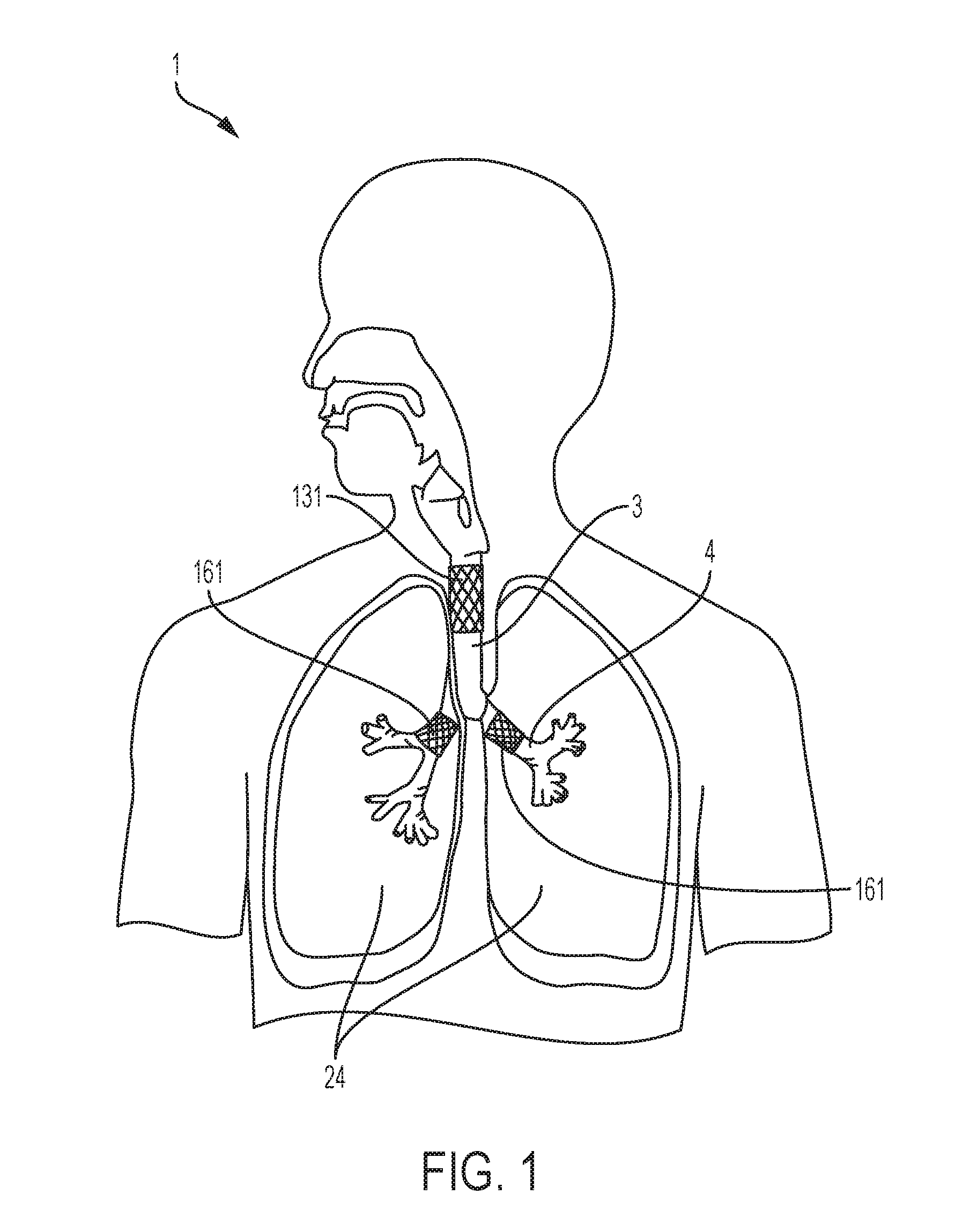
[0021] FIG. 1 is a diagrammatical anterior view illustrating the positioning of several embodiments of a stent in the respiratory tract, specifically the positioning of a stent in the tracheal and bronchial fistulae.
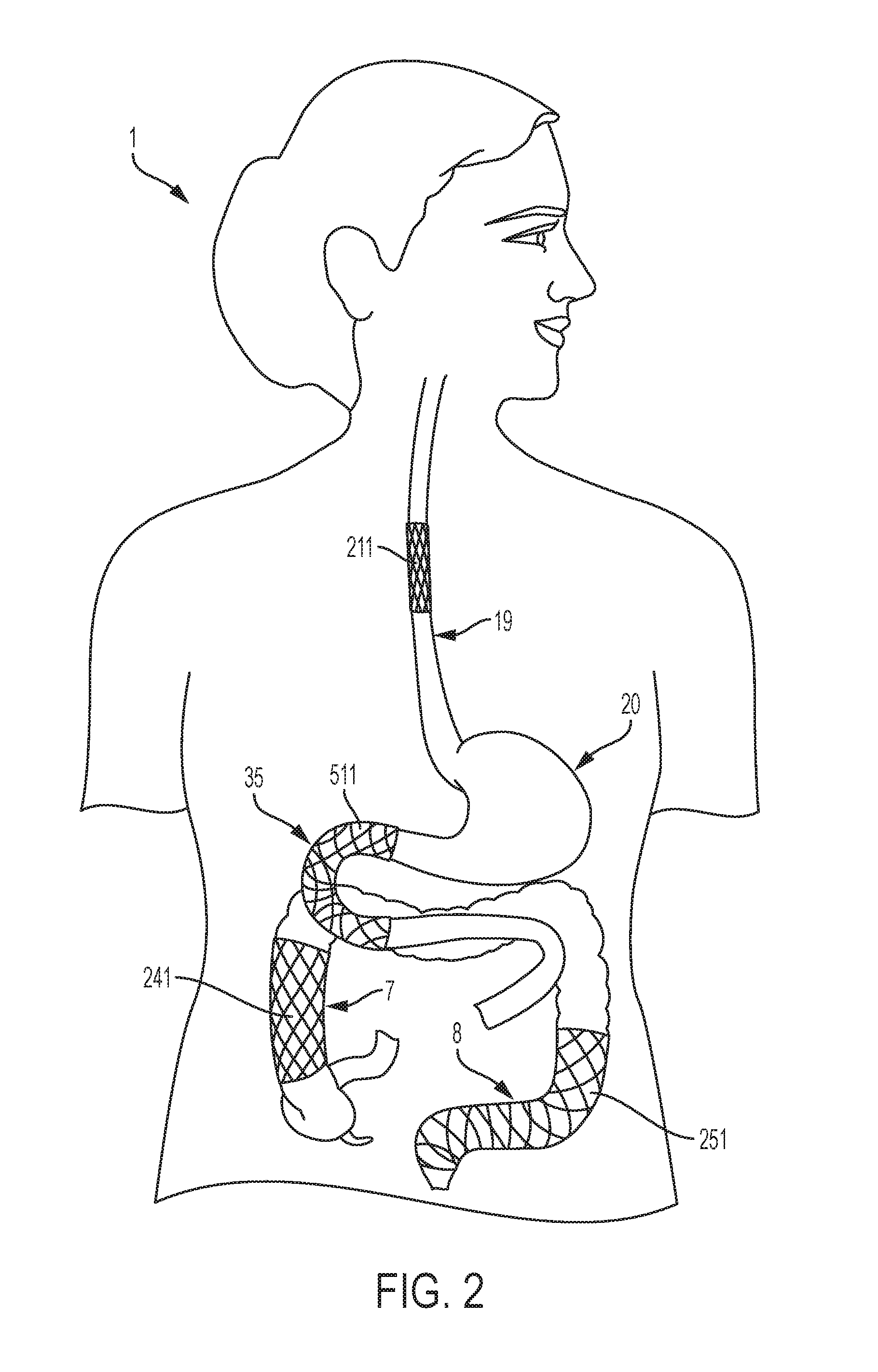
[0022] FIG. 2 is a diagrammatical anterior view illustrating the position of several embodiments of a stent in the gastrointestinal tract, specifically the esophagus, duodenum, right colon, and left colon.
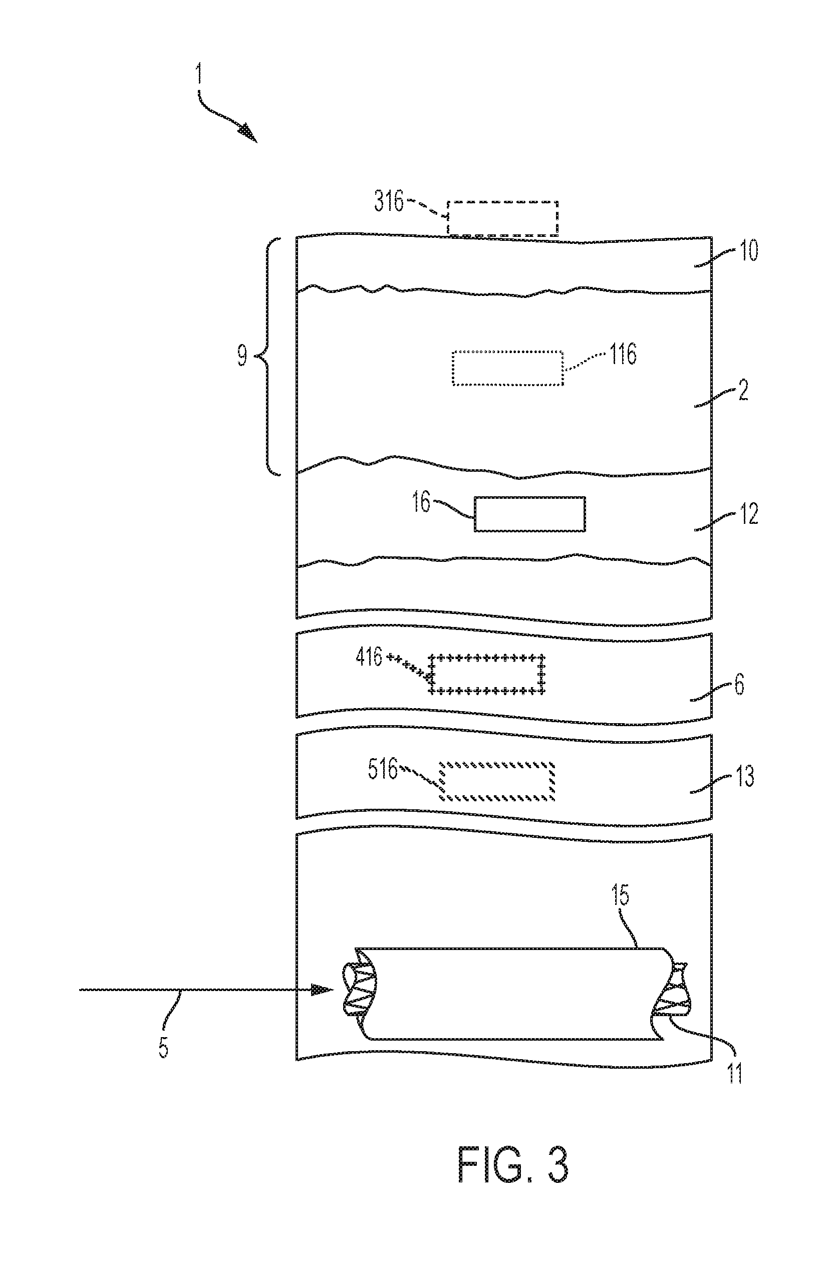
[0023] FIG. 3 is an abstract cross-sectional view of the positioning of both a stent and a corresponding magnet depicting the stent located in an anatomical lumen and the magnet located in the subcutaneous, muscular, or sub-fascial tissue or located in or on the cutaneous layer of the subject after a stent delivery tool has inserted the stent into the anatomical lumen.
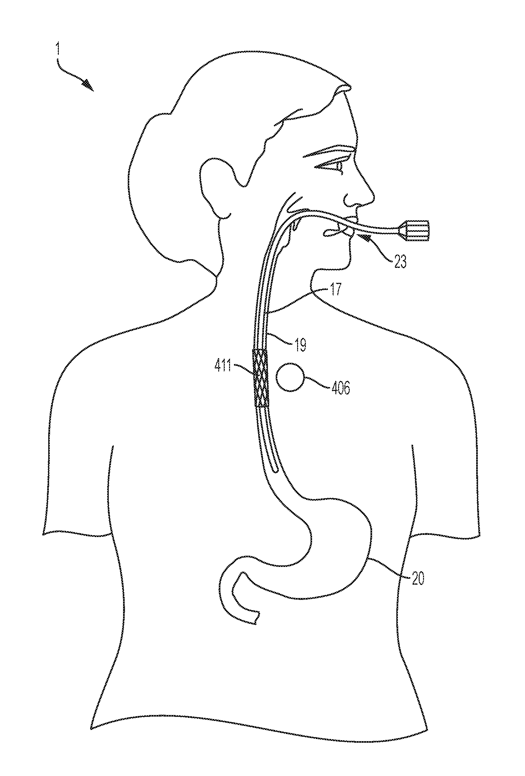
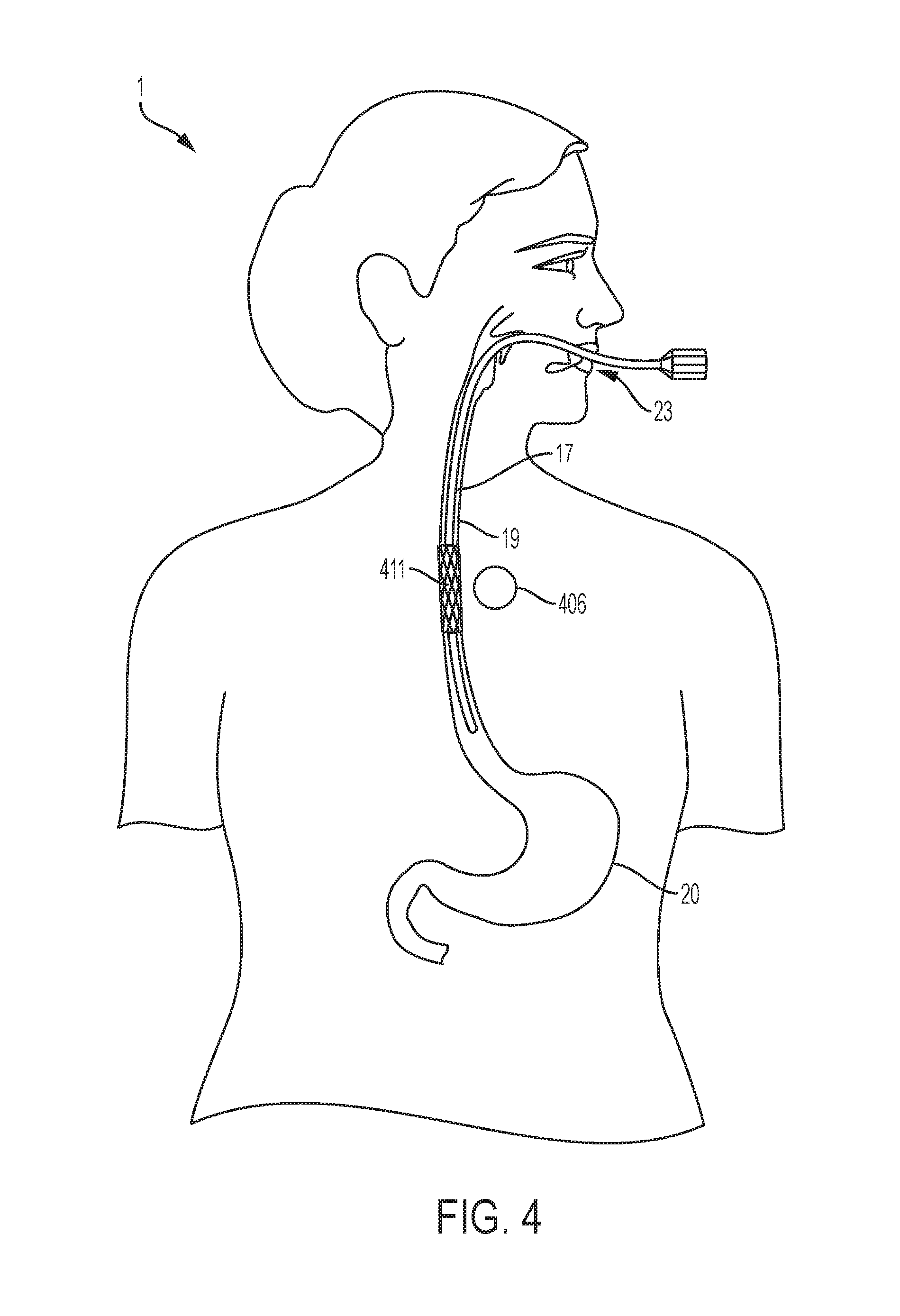
[0024] FIG. 4 is a diagrammatical anterior view illustrating one possible location of the magnet that could be used to fix a stent in the esophagus after the stent has been inserted through a conventional endoscopic method.
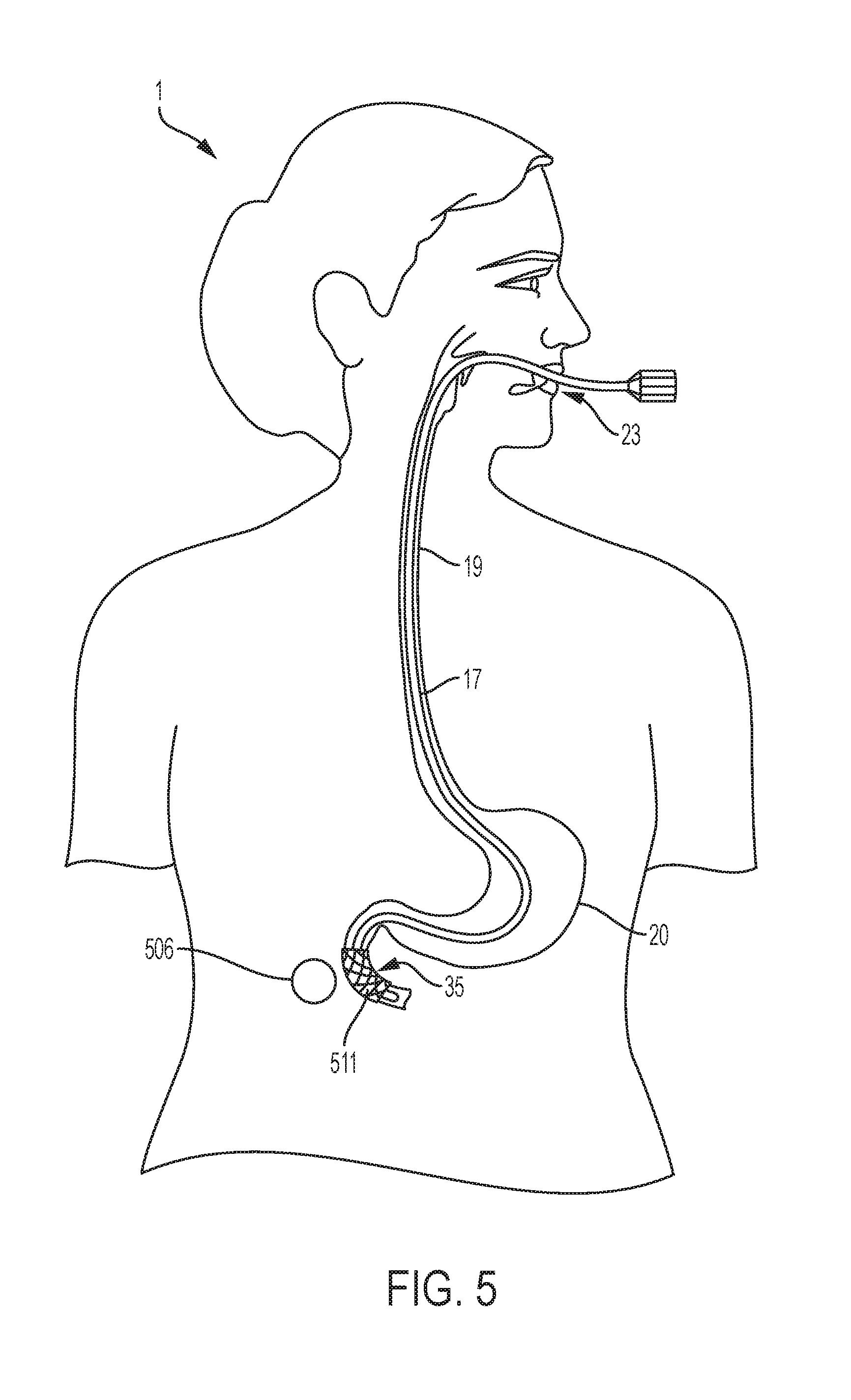
[0025] FIG. 5 is a diagrammatical anterior view illustrating one possible location of the magnet that could be used to fix a stent in the duodenum after the stent has been inserted through a conventional endoscopic method.
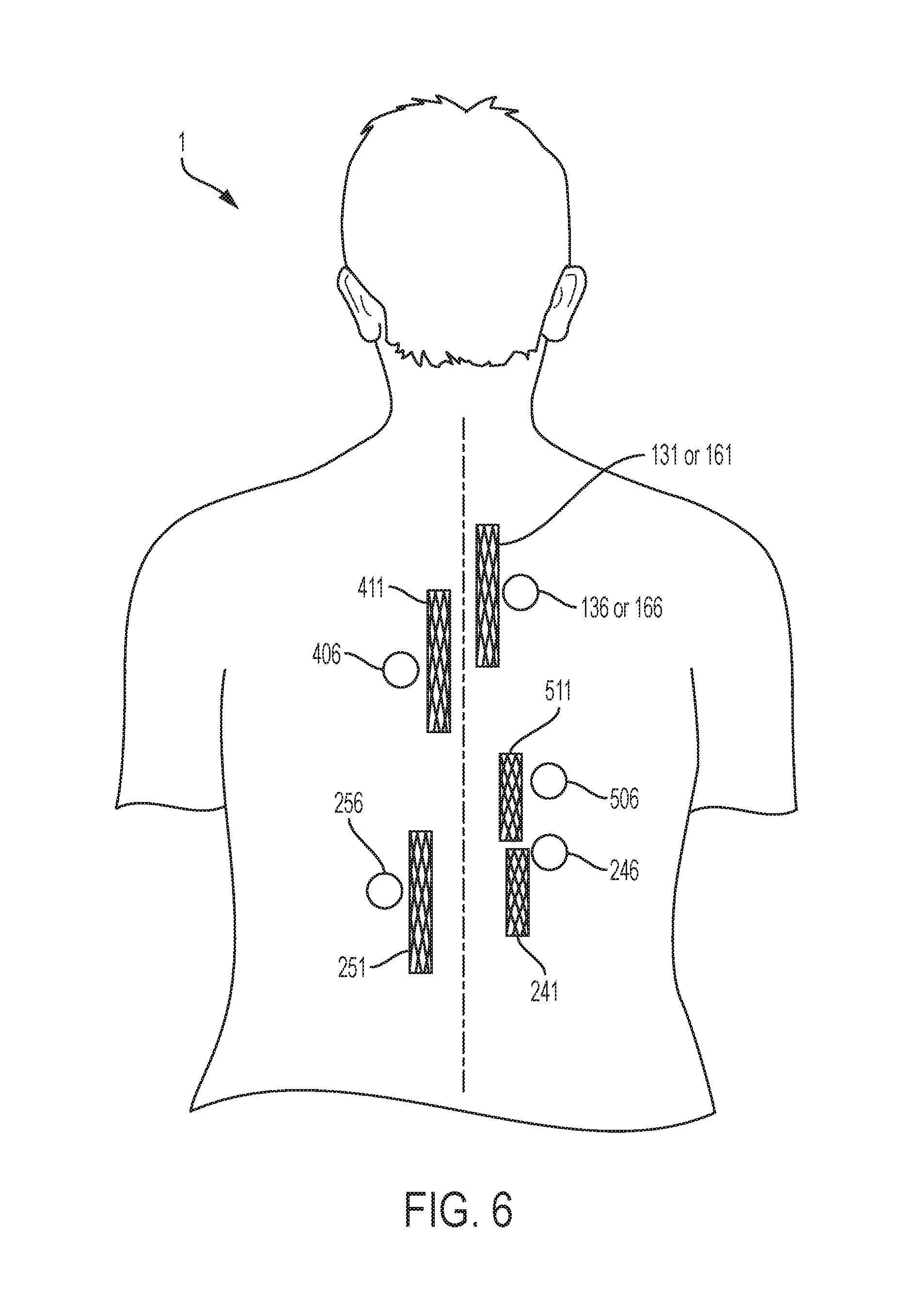
[0026] FIG. 6 is an abstract posterior view of possible locations of magnets to fix the corresponding stent, including stents in the trachea, bronchi, esophagus, duodenum, left colon, and right colon.
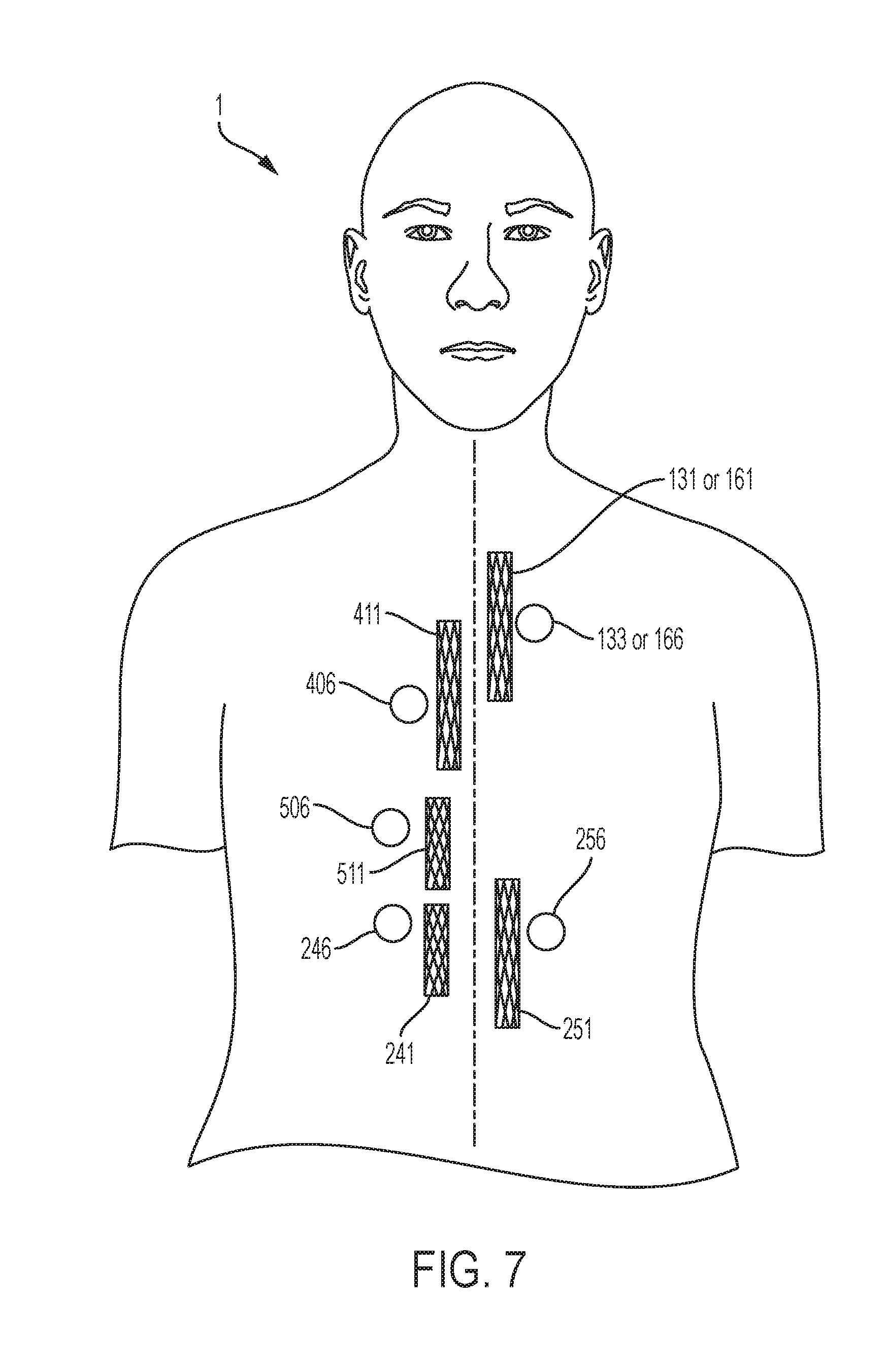
[0027] FIG. 7 is an abstract anterior view of possible locations of magnets to fix the corresponding stent, including stents in the trachea, bronchi, esophagus, duodenum, left colon, and right colon.
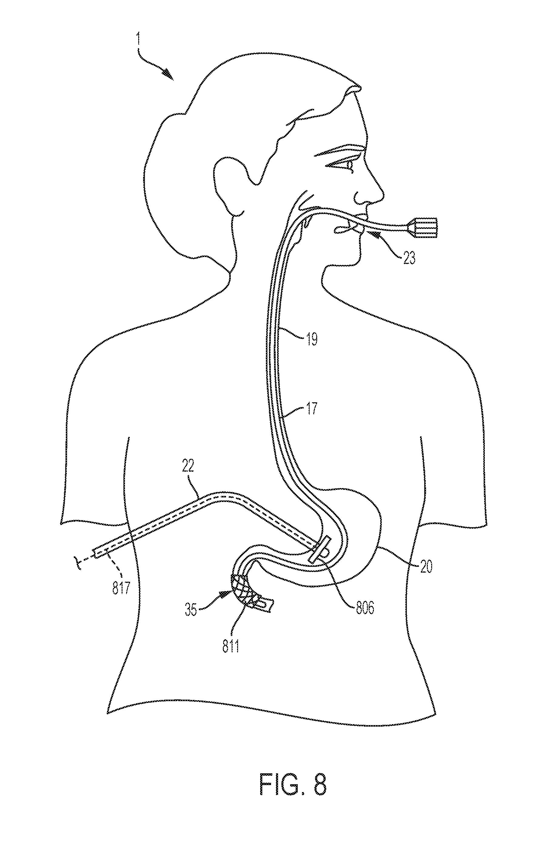
[0028] FIG. 8 is a diagrammatical anterior view illustrating one possible location of the magnet on a gastronomy tube in the stomach so as to fix a stent in the duodenum after the stent has been inserted through a conventional endoscopic method.
DETAILED DESCRIPTION OF EXEMPLARY EMBODIMENTS
[0029] An aspect of an embodiment of the present invention provides, among other things, the analytical tools and method to fix an intra-luminal stent in position using magnetic forces. An aspect of an embodiment of the present invention provides, but not limited thereto, guidance that shall facilitate the use of a minimally invasive medical system and method to fix an intra-luminal stent in position that minimizes the possibility of tissue and organ damage. Although the systems and methods disclosed herein describe stents located in the respiratory and gastrointestinal tract, as depicted in FIG. 1 and FIG. 2, the stents may be located in any anatomical lumen or organ of the subject. For example, the stents could be positioned in the biliary or pancreatic ducts. Additionally, although the systems and methods disclosed herein describe a magnet 16 positioned in the subcutaneous tissue 12 of the subject 1, as depicted in FIG. 3. Still referring to FIG. 3, the magnet 416 may be positioned in the intra-muscular layer 6 (i.e., the magnet is positioned in the muscle, as depicted by the cross-hatch lines referenced as 416) or the magnet 516 may be positioned sub-fascial layer 13 (i.e., the magnet is positioned below the muscle, and above the body cavity, as depicted by the slanted lines referenced as 516) of the subject 1. In an embodiment, the magnet 16 is implanted in the respective layer of the subject 1.
[0030] In another embodiment, the magnet 316 may be positioned on the cutaneous layer 9 of the subject 1 (e.g., disposed on the surface of the subject or exterior to the surface of the subject, as depicted by the dashed lines referenced as 316). For implementation on the cutaneous layer 9 (e.g., disposed on the surface of the subject 1 or exterior to the surface of the subject 1) the magnet 316 may be affixed to the epidermis 10 of the subject 1 through the use of an adhesive or may be incorporated into a wearable garment.
[0031] In another embodiment, the magnet may be positioned in the cutaneous layer 9 of the subject 1, which includes the epidermis 10 and dermis 2, as depicted by the dotted lines referenced as 116 in FIG. 3. For implementation in the cutaneous layer 9 of the subject 1 the magnet 116 may be implanted in the cutaneous layer 9, which includes the epidermis 10 and dermis 2 of the subject.
[0032] In order to more clearly and concisely describe the subject matter of the claims, the following definition is intended to provide guidance as to the meaning of a specific term used in the following written description, examples, and appended claims. As used herein, the term anatomical lumen means a lumen corresponding to an organ of the subject. The term anatomical lumen includes, but is not limited to, the inside of the duodenum, the inside of the colon, the inside of the esophagus, and the inside of the trachea and bronchi.
[0033] Practice of the invention will be still more fully understood from the following examples, which are presented herein for illustration only and should not be construed as limiting the invention in any way.
[0034] FIG. 1 and FIG. 2 depict possible locations of stents utilizing an embodiment of the present invention, including the aforementioned examples of an esophageal stent 211 and a duodenal stent 511, both of which are depicted in FIG. 2; and whereby FIG. 1 depicts possible locations of stents in the respiratory tract of the subject 1. For example, FIG. 1 depicts a tracheal stent 131 in the trachea 3 as well as a bronchial stent 161 in each bronchi 4 of the subject 1. It is to be appreciated that the stents may be positioned in any anatomical lumen 15 of the respiratory system not included in FIG. 1. FIG. 2 depicts possible locations of stents in the gastrointestinal tract of the subject 1. FIG. 2 depicts an esophageal stent 211 in the esophagus 19, a duodenal stent 511 in the duodenum 35, a right colon stent 241 in the right, ascending colon 7, and a left colon stent 251 in the left, descending colon 8. It is to be appreciated that multiple stents in multiple anatomical lumens or multiple anatomical systems can be fixed simultaneously using an embodiment of the present invention.
[0035] FIG. 3 is an abstract depiction of the concept behind an embodiment of the invention. A stent 11 is inserted into an anatomical lumen 15 of the subject 1 via an available system delivery tool 5 (for example, endoscope or the like). A magnet 16 is then inserted into the subcutaneous layer 12 of the subject 1 such that the magnetic coupling between the magnet 16 and the stent 11 fixes the stent 11 in position within the anatomical lumen 15. FIG. 3 also depicts other possible locations for the magnet 16. As described above, the magnet can also be positioned in on the cutaneous layer of the subject 1 exterior to the surface of the subject, as depicted by the dashed lines referenced as 316. The magnet can also be positioned in the subcutaneous layer 9, for example, positioned in the dermis 2 as depicted by the dotted lines referenced as 116. The magnet can also be positioned in the muscular layer 6, as depicted by the cross-hatch lines referenced as 416. The magnet can also be positioned in the sub-fascial layer 13 below the muscle, and above the body cavity, as depicted by the slanted lines referenced as 516.
[0036] An example of one potential use of an aspect of an embodiment of the system is represented in FIG. 4. In order to help seal a perforation in the esophagus 19, a stent is desired. However, the motility of the esophagus 19 makes movement of the stent likely. Additionally, the delicate nature of the esophageal wall makes the use of large externally-oriented radial forces, friction, or the use of fasteners to the esophageal mucosa less than ideal. Reliance on such forces is associated with tissue damage. Instead, turning to an aspect of an embodiment of the present invention, information from cross-sectional imaging of the chest is used to determine the best location of the esophageal stent 411 as well as the area of subcutaneous tissue 12 (as shown in FIG. 3, for example) close to the proposed stenting area to be used for the esophagus magnet 406 placement. Technology such as computerized tomography is suitable for such cross-sectional imaging. Other equivalent imaging technologies would also be suitable. Identification of imaging equivalents are within the skill of the ordinary practitioner and would require no more than routine experimentation
[0037] Still referring to FIGS. 3 and 4, the esophageal stent 411 would then be inserted into the esophagus 19 through, for example, a procedure such as an endoscopic procedure. FIG. 4 illustrates the use of an endoscope 17 for the placement of an esophageal stent 411. In an endoscopic procedure, the subject is sedated through general anesthesia and undergoes endoscopic placement of the stent. Procedurally, when a stent is inserted endoscopically, the stent may begin in a collapsed state. Once the endoscope 17 reaches the desired location for stent placement, the stent is then allowed to expand through a self-expanding mechanism (as well as other available stent expandable mechanisms or materials). It is to be appreciated that other equivalent procedures for stent placement would also be suitable. It is to be appreciated that other equivalent procedures for expanding the stent would also be suitable. Identification of stent placement procedures are within the skill of the ordinary practitioner and would require no more than routine experimentation. During the same session, a magnet 16 or 406 is implanted in the subcutaneous tissue 9 of the subject 1 through available procedures similar to procedures for port or pacemaker placement. For example, a small incision is made and pocket created in the subcutaneous layer 12. An appropriately chosen magnet 16 is then placed into the pocket and the skin closed.
[0038] FIG. 6 and FIG. 7 depict examples of magnet placements relative to the corresponding stent in order for some embodiments of the invention in order to fix said stent in position. FIG. 6 is a posterior view of the subject 1 providing an example of a possible position for a tracheal magnet 136 to fix a tracheal stent 131 in position. As described above, in one embodiment of the invention the tracheal magnet 136 will be implanted in the cutaneous layer 12 of the subject 1 as demonstrated in FIG. 3. With respect to that embodiment of the invention, the tracheal magnet 136 in FIG. 6 represents a possible position of the tracheal magnet 136 within the cutaneous layer 12 in FIG. 3 of the subject 1. Similarly, FIG. 6 provides examples of possible positions for a bronchial magnet 166 to fix a bronchial stent 161 in position, an esophageal magnet 406 to fix an esophageal stent 411 in position, a duodenal magnet 506 to fix a duodenal stent 511 in position, a right, ascending colon magnet 246 to fix a right, ascending colon stent 241 in position, and a left, descending colon magnet 256 to fix a left, descending colon stent 251 in position. FIG. 7 depicts the same stents and magnets, for example, as FIG. 6 but from the anterior view of the subject 1.
[0039] To determine the size, shape, and strength of the magnet, an aspect includes examining the characteristics of the stent itself, including the size, shape, material, and magnetic attraction, as well as the distance and location of the corresponding magnet. Compounds such as metals, ferrous materials, or magnetizable materials are suitable for the stent. Other equivalent substances for the stent would also be suitable. Identification of equivalents is within the skill of the ordinary practitioner and would require no more than routine experimentation. It is to be appreciated that the stent may be composed of such compounds in part or in whole. In an embodiment the stent may be composed entirely of a metal or some other non-ferrous material that can be magnetically coupled to a magnet. In an embodiment the stent may be made of a biocompatible material or coated with a material, e.g. silicone, to achieve biocompatibility. The stent may also be designed to be flexible and/or expandable. In an embodiment, the stent is flexible in order to be able to follow the contours of the anatomical lumen into which it is inserted. In another embodiment, the stent is expandable such that when the stent is inserted, the stent may begin in a collapsed state. Once the stent reaches the desired location for stent placement, the stent is then allowed to expand. An aspect of an embodiment may comprise a stent or magnet that may include using a balloon or any other suitable implantation method to expand the stent, as well as a self-expanding mechanism.
[0040] The insertion of a duodenal stent 511 into the duodenum 35 through the use of an endoscope 17 as depicted in FIG. 5 is a good example of when a stent that is both expandable and flexible is preferable. As depicted in FIG. 5, in an embodiment of the invention the stent is able to follow the contours of the duodenum. FIG. 5 is another example of one potential use of an aspect of an embodiment of the system. Similarly to the embodiment depicted in FIG. 4, in order to help seal a perforation in the duodenum 35, a stent is desired. Just as in the esophagus 19 depicted in FIG. 4, motility of the duodenum 35 makes movement of the duodenal stent 511 likely. The duodenum wall is also delicate, which makes the use of a duodenum magnet 506 for fixation of the duodenal stent 511 a desirable aspect of an embodiment of the present invention. As described in the above description of an embodiment depicted in FIG. 4, the stent can be inserted with an endoscope 17. Procedurally, when a stent is inserted endoscopically, the stent may begin in a collapsed state. Once the endoscope reaches the desired location for stent placement, the stent is then allowed to expand. The benefits of flexibility are twofold: the stent must be able to bend with the endoscope 17 through the gastrointestinal tract, as depicted in FIG. 5, and the duodenal stent 511 must be able to fit the curvature of the duodenum 35, as depicted in FIG. 5.
[0041] With respect to the magnet, compounds such as metals, ferrous materials, or magnetizable materials are likewise suitable. Other equivalent substances for the magnet would also be suitable. Identification of equivalents is within the skill of the ordinary practitioner and would require no more than routine experimentation. It is to be appreciated that the magnet may be composed of such compounds in part or in whole. In an embodiment, the magnet may be composed entirely of a ferrous material. Such material may be biocompatible, or may be coated with a material, e.g. silicone, to achieve biocompatibility. While it is to be appreciated that the magnet may be any size or shape appropriate for the fixation of a corresponding stent, an embodiment may include a thin, round magnet. The round nature is beneficial for implants generally in order to minimize tissue damage. The thinness is beneficial with respect to the embodiment of the invention wherein, as depicted in FIG. 3 the magnet 16 is implanted into the subcutaneous tissue 12, as the tissue layer may be thin. Identification of equivalents is within the skill of the ordinary practitioner and would require no more than routine experimentation. It is to be appreciated that the placement of two or more magnets might be desirable to minimize mal-positioning, eccentric placement, or migration of the stent. For example, one magnet may be positioned on either side of the anatomical lumen such as one at the posterior and one at the anterior of the subject relative to the intra-luminal stent.
[0042] When the stent is no longer needed, in an embodiment it is removed endoscopically and the magnet or magnets may be removed under local anesthesia. It is to be appreciated that the stent may also be removed through natural peristalsis. Such an embodiment would be used, for example, for a duodenal stent 35, as depicted in FIG. 5. In that embodiment of the invention, the duodenal magnet 506 or magnets may be removed under local anesthesia and the stent would remain in place. Over time, the stent would advance through the gastrointestinal tract due to peristalsis and exit the gastro-intestinal tract naturally. Additionally, it is to be appreciated that the stent could be removed through open surgery.
[0043] Another example of one potential use of an aspect of an embodiment of the system is represented in FIG. 8. In this embodiment of the invention, a duodenal stent 811 may be inserted endoscopically. Procedurally, when a stent is inserted endoscopically, the stent may begin in a collapsed state. Once the endoscope 17 reaches the desired location for stent placement, which in this case is the duodenum 35, the stent is then allowed to expand through a self-expanding mechanism. Identification of stent placement procedures are within the skill of the ordinary practitioner and would require no more than routine experimentation. During the same session, a magnet may be placed on a gastronomy tube 22 that is inserted into the stomach 20 of the subject 1 through conventional procedures. In this embodiment, the gastronomy tube magnet 806 remains attached solely to the gastronomy tube 22, which is held in position by virtue of the gastronomy tube placement.
[0044] In an embodiment, such as shown in FIG. 8, to fix a duodenal stent 811 in position the magnet 806 may be located in the stomach 20, affixed to the end of a gastronomy tube 22 without requiring attachment to or implantation in the organ tissue. In this embodiment, the gastronomy tube magnet 806 remains attached solely to the gastronomy tube 22, which is held in position by virtue of the gastronomy tube placement. In another embodiment, as discussed regarding FIG. 5, the duodenal magnet 506 may be inserted endoscopically (via the endoscope 17) within the gastrointestinal tract such as within the duodenum 35 itself, held in position by virtue of the of the endoscope 17 placement.
[0045] Still referring to FIG. 8, for example, to determine the size, shape, and strength of the magnet, one skilled in the art will examine the characteristics of the stent itself, including the size, shape, material, and magnetic attraction, as well as the distance and location of the corresponding magnet. Compounds such as metals, ferrous materials, or magnetizable materials are suitable for the stent. Other equivalent substances for the stent would also be suitable. Identification of equivalents is well within the skill of the ordinary practitioner and would require no more than routine experimentation. It is to be appreciated that the stent may be composed of such compounds in part or in whole. In an embodiment the stent may be composed entirely of a metal or some other non-ferrous material that can be magnetically coupled to a magnet. In an embodiment the stent may be made of a biocompatible material or coated with a material, e.g. silicone, to achieve biocompatibility. The stent may also be designed to be flexible and/or expandable. In an embodiment of the invention, the stent is flexible to follow the contours of the anatomical lumen. In another embodiment, the stent is expandable such that when the stent is inserted, the stent may begin in a collapsed state. Once the stent reaches the desired location for stent placement, the stent is then allowed to expand. Still referring to FIG. 8, for example, with respect to the magnet, compounds such as metals, ferrous materials, or magnetizable materials are likewise suitable. Other equivalent substances for the magnet would also be suitable. Identification of equivalents is well within the skill of the ordinary practitioner and would require no more than routine experimentation. It is to be appreciated that the magnet may be composed of such compounds in part or in whole. In an embodiment, the magnet may be composed entirely of a ferrous material. Such material may be biocompatible, or may be coated with a material, e.g. silicone, to achieve biocompatibility. It is to be appreciated that the magnet may be any shape or size appropriate for the fixation of a corresponding stent. It is to be appreciated that the placement of two magnets might be desirable to minimize mal-positioning, eccentric placement, or migration of the stent. For example, one magnet may be positioned on the end of a gastronomy tube 22 in the stomach 20 (or on a first endoscope 817 in the gastronomy tube 22) and another may be positioned on the end of a second endoscope, such as the endoscope 17 running in the esophagus 19 in part, or positioned on another endoscope (not shown) in the duodenum 35.
[0046] When the stent is no longer needed, in an embodiment it is removed endoscopically and the magnet is removed through removal of the gastronomy tube 22. It is to be appreciated that the stent may also be removed through natural peristalsis. Such an embodiment would be used, for example, for a duodenal stent 811, as depicted in FIG. 8. In that embodiment of the invention, the magnet or magnets may be removed through removal of the gastronomy tube 22 or in an embodiment, an endoscope 817 running through the gastronomy tube 22. Alternatively, the magnet or magnets may be removed through endoscope 17 running through the gastrointestinal tract. Over time, the stent would advance through the gastrointestinal tract due to peristalsis and exit the gastro-intestinal tract naturally. Additionally, it is to be appreciated that the stent could be removed through open surgery.
[0047] Generally referring to aspects of FIGS. 1-4, for instance, in another embodiment, the magnet 16 may be located remotely within the anatomical lumen in which the stent 1 is positioned, or in another, second anatomical lumen. For example, to fix an esophageal stent 411 as shown in FIG. 4, a magnet may be affixed to an endoscope 17 and positioned in a portion of the esophagus 19 at a position distant from the stent 411 itself. This positioning of the magnet occurs without attachment to or implantation in the organ tissue. Rather, the magnet remains attached solely to the endoscope 17, which is held in position mechanically.
[0048] In an embodiment, delivery of magnets may also be achieved through the use of catheters or other medical devices, equipment, tools or instruments, whereby a collapsed magnet is inserted into the intended location or anatomical lumen or region. Once the magnet reaches the desired location or anatomical lumen or region for magnet placement, the magnet is then allowed to expand through a self-expanding mechanism (as well as other available expansion or deployment mechanisms or materials). In an embodiment, the magnet may also be designed to be flexible. In an embodiment, the magnet may be flexible in order to be able to follow the contours of the anatomical region or lumen (or other location) into which it is inserted, placed or disposed. Any of the components (or sub-components) disclosed herein may have similar expansion and flexibility design characteristics and performance.
[0049] Any of the components or modules referred to with regards to any of the present invention embodiments of the device discussed herein, may be integrally or separately formed with one another. Further, redundant functions or structures of the components or modules may be implemented.
[0050] Any of the components or modules may be a variety of widths and lengths as desired or required for operational purposes.
[0051] It should be appreciated that various sizes, dimensions, contours, rigidity, shapes, flexibility and materials of any of the components or portions of components in the various embodiments of the device discussed throughout may be varied and utilized as desired or required. Similarly, locations and alignments of the various components may vary as desired or required. Moreover, modes and mechanisms for connectivity or interchangeability may vary.
[0052] It should be appreciated that the device (and system) and related components of the device (and system) discussed herein may take on all shapes along the entire continual geometric spectrum of manipulation of x, y, and z planes to provide and meet the anatomical, environmental, and structural demands and operational requirements. Moreover, locations and alignments of the various components may vary as desired or required.
[0053] It should be appreciated that as discussed herein, a subject may be a human or any animal. It should be appreciated that an animal may be a variety of any applicable type, including, but not limited thereto, mammal, veterinarian animal, livestock animal or pet type animal, etc. As an example, the animal may be a laboratory animal specifically selected to have certain characteristics similar to human (e.g. rat, dog, pig, monkey), etc. It should be appreciated that the subject may be any applicable human patient, for example.
[0054] Although illustrative variations of the present invention are described above, it will be evident to one skilled in the art that various changes and modifications may be made without departing from the invention. It is intended in the following claims to cover all such changes and modifications that fall within the true spirit and scope of the invention.
EXAMPLES
[0055] Practice of an aspect of an embodiment (or embodiments) of the invention will be still more fully understood from the following examples and experimental results, which are presented herein for illustration only and should not be construed as limiting the invention in any way.
Example 1
[0056] A medical system for fixing a stent in position within an anatomical lumen of a subject. The medical system may comprise: an intra-luminal stent; and a magnet wherein said magnet is configured to be implanted in the subject in one or more of the following locations: the subcutaneous layer of the subject, the intra-muscular layer of the subject, or the sub-fascial layer of the subject. And wherein a magnetic force between said intra-luminal stent and said magnet is configured to fix said stent in position.
Example 2
[0057] The medical system of example 1, wherein said stent is composed of a material selected from the group consisting of a magnet, a magnetizable material, and a magnetic metal.
Example 3
[0058] The medical system of example 1 (as well as subject matter in whole or in part of example 2), wherein said magnet is composed of a material selected from the group consisting of a magnet, a magnetizable material, and a magnetic metal.
Example 4
[0059] The medical system of example 1 (as well as subject matter of one or more of any combination of examples 2-3, in whole or in part), wherein said stent is expandable.
Example 5
[0060] The medical system of example 1 (as well as subject matter of one or more of any combination of examples 2-4, in whole or in part), wherein said stent is designed to be flexible to follow the contours of said anatomical lumen.
Example 6
[0061] The medical system of example 1 (as well as subject matter of one or more of any combination of examples 2-5, in whole or in part), wherein said stent is located in the respiratory tract.
Example 7
[0062] The medical system of example 1 (as well as subject matter of one or more of any combination of examples 2-6, in whole or in part), wherein said stent is located in the gastrointestinal tract.
Example 8
[0063] The medical system of example 1 (as well as subject matter of one or more of any combination of examples 2-7, in whole or in part), wherein said stent is inserted endoscopically.
Example 9
[0064] The medical system of example 1 (as well as subject matter of one or more of any combination of examples 2-8, in whole or in part), wherein said stent is configured to be advanced by peristaltic contractions.
Example 10
[0065] The medical system of example 1 (as well as subject matter of one or more of any combination of examples 2-9, in whole or in part), wherein said stent is removed through open surgery.
Example 11
[0066] The medical system of example 1 (as well as subject matter of one or more of any combination of examples 2-10, in whole or in part), wherein said stent is removed endoscopically.
Example 12
[0067] The medical system of example 1 (as well as subject matter of one or more of any combination of examples 2-11, in whole or in part), wherein said stent is removed by advancing through the lumen naturally.
[0068] 13. The medical system of example 12 (as well as subject matter of one or more of any combination of examples 2-11, in whole or in part), wherein said stent is configured to be advanced by peristaltic contractions.
Example 14
[0069] The medical system of example 1 (as well as subject matter of one or more of any combination of examples 2-13, in whole or in part), wherein multiple of said magnets are used to fix said stent in position.
Example 15
[0070] The medical system of example 1 (as well as subject matter of one or more of any combination of examples 2-14, in whole or in part), wherein said magnetic force is adjusted by the size, strength, and location of said magnet.
Example 16
[0071] A method for fixing a medical stent in position of a subject. The method may comprise: inserting a stent in an anatomical lumen; implanting a magnet in the subject in one or more of the following locations: the subcutaneous layer of the subject, the intra-muscular layer of the subject, or the sub-fascial layer of the subject; and employing a magnetic force between said stent and said magnet to fix said stent in position.
Example 17
[0072] The method of example 16, wherein said stent is composed of a material selected from the group consisting of a magnet, a magnetizable material, and a magnetic metal.
Example 18
[0073] The method of example 16 (as well as subject matter in whole or in part of example 17), wherein said magnet is composed of a material selected from the group consisting of a magnet, a magnetizable material, and a magnetic metal.
Example 19
[0074] The method of example 16 (as well as subject matter of one or more of any combination of examples 17-18, in whole or in part), wherein said stent is expandable.
Example 20
[0075] The method of example 16 (as well as subject matter of one or more of any combination of examples 17-19, in whole or in part), wherein said stent is designed to be flexible to follow the contours of said anatomical lumen.
Example 21
[0076] The method of example 16 (as well as subject matter of one or more of any combination of examples 17-20, in whole or in part), wherein said stent is located in the respiratory tract.
Example 22
[0077] The method of example 16 (as well as subject matter of one or more of any combination of examples 17-21, in whole or in part), wherein said stent is located in the gastrointestinal tract.
Example 23
[0078] The method of example 16 (as well as subject matter of one or more of any combination of examples 17-22, in whole or in part), wherein said stent is inserted endoscopically.
Example 24
[0079] The medical system of example 16 (as well as subject matter of one or more of any combination of examples 17-23, in whole or in part), wherein said stent is configured to be advanced by peristaltic contractions.
Example 25
[0080] The method of example 16 (as well as subject matter of one or more of any combination of examples 17-24, in whole or in part), wherein said stent is removed by advancing through the lumen naturally.
Example 26
[0081] The method of example 25 (as well as subject matter of one or more of any combination of examples 17-24, in whole or in part), wherein said stent is configured to be advanced by peristaltic contractions.
Example 27
[0082] The method of example 16 (as well as subject matter of one or more of any combination of examples 17-26, in whole or in part), wherein said stent is removed through open surgery.
Example 28
[0083] The method of example 16 (as well as subject matter of one or more of any combination of examples 17-27, in whole or in part), wherein said stent is removed endoscopically.
Example 29
[0084] The method of example 16 (as well as subject matter of one or more of any combination of examples 17-28, in whole or in part), wherein multiple of said magnets are used to fix said stent in position.
Example 30
[0085] The method of example 16 (as well as subject matter of one or more of any combination of examples 17-29, in whole or in part), wherein said magnetic force is adjusted by the size, strength, and location of said magnet.
Example 31
[0086] A medical system for fixing a stent in position within an anatomical lumen of a subject. The medical system may comprise: an intra-luminal stent; a magnet wherein said magnet is configured to be disposed on the subject disposed on a cutaneous location; and wherein a magnetic force between said intra-luminal stent and said magnet is configured to fix said stent in position.
Example 32
[0087] The medical system of example 31, wherein said stent is composed of a material selected from the group consisting of a magnet, a magnetizable material, and a magnetic metal.
Example 33
[0088] The medical system of example 31 (as well as subject matter in whole or in part of example 32), wherein said magnet is composed of a material selected from the group consisting of a magnet, a magnetizable material, and a magnetic metal.
Example 34
[0089] The medical system of example 31 (as well as subject matter of one or more of any combination of examples 32-33, in whole or in part), wherein said stent is expandable.
Example 35
[0090] The medical system of example 31 (as well as subject matter of one or more of any combination of examples 32-34, in whole or in part), wherein said stent is designed to be flexible to follow the contours of said anatomical lumen.
Example 36
[0091] The medical system of example 31 (as well as subject matter of one or more of any combination of examples 32-35, in whole or in part), wherein said stent is located in the respiratory tract.
Example 37
[0092] The medical system of example 31 (as well as subject matter of one or more of any combination of examples 32-36, in whole or in part), wherein said stent is located in the gastrointestinal tract.
Example 38
[0093] The medical system of example 31 (as well as subject matter of one or more of any combination of examples 32-37, in whole or in part), wherein said stent is inserted endoscopically.
Example 39
[0094] The medical system of example 31 (as well as subject matter of one or more of any combination of examples 32-38, in whole or in part), wherein said stent is configured to be advanced by peristaltic contractions.
Example 40
[0095] The medical system of example 31 (as well as subject matter of one or more of any combination of examples 32-39, in whole or in part), wherein said stent is removed through open surgery.
Example 41
[0096] The medical system of example 31 (as well as subject matter of one or more of any combination of examples 32-40, in whole or in part), wherein said stent is removed endoscopically.
Example 42
[0097] The method of example 31 (as well as subject matter of one or more of any combination of examples 32-41, in whole or in part), wherein said stent is removed by advancing through the lumen naturally.
Example 43
[0098] The method of example 42 (as well as subject matter of one or more of any combination of examples 32-41, in whole or in part), wherein said stent is configured to be advanced by peristaltic contractions.
Example 44
[0099] The medical system of example 31 (as well as subject matter of one or more of any combination of examples 32-43, in whole or in part), wherein multiple of said magnets are used to fix said stent in position.
Example 45
[0100] The medical system of example 31 (as well as subject matter of one or more of any combination of examples 32-44, in whole or in part), wherein said magnetic force is adjusted by the size, strength, and location of said magnet.
Example 46
[0101] A method for fixing a medical stent in position of a subject. The method may comprise: inserting a stent in an anatomical lumen; configuring a magnet on the subject disposed on a cutaneous location; and employing a magnetic force between said stent and said magnet to fix said stent in position.
Example 47
[0102] The method of example 46, wherein said stent is composed of a material selected from the group consisting of a magnet, a magnetizable material, and a magnetic metal.
Example 48
[0103] The method of example 46 (as well as subject matter in whole or in part of example 47), wherein said magnet is composed of a material selected from the group consisting of a magnet, a magnetizable material, and a magnetic metal.
Example 49
[0104] The method of example 46 (as well as subject matter of one or more of any combination of examples 47-48, in whole or in part), wherein said stent is expandable.
Example 50
[0105] The medical system of example 46 (as well as subject matter of one or more of any combination of examples 47-49, in whole or in part), wherein said stent is designed to be flexible to follow the contours of said anatomical lumen.
Example 51
[0106] The method of example 46 (as well as subject matter of one or more of any combination of examples 47-50, in whole or in part), wherein said stent is located in the respiratory tract.
Example 52
[0107] The method of example 46 (as well as subject matter of one or more of any combination of examples 47-51, in whole or in part), wherein said stent is located in the gastrointestinal tract.
Example 53
[0108] The method of example 46 (as well as subject matter of one or more of any combination of examples 47-52, in whole or in part), wherein said stent is inserted endoscopically.
Example 54
[0109] The method of example 46 (as well as subject matter of one or more of any combination of examples 47-53, in whole or in part), wherein said stent is configured to be advanced by peristaltic contractions.
Example 55
[0110] The method of example 46 (as well as subject matter of one or more of any combination of examples 47-54, in whole or in part), wherein said stent is removed through open surgery.
Example 56
[0111] The method of example 46 (as well as subject matter of one or more of any combination of examples 47-55, in whole or in part), wherein said stent is removed endoscopically.
Example 57
[0112] The method of example 46 (as well as subject matter of one or more of any combination of examples 47-56, in whole or in part), wherein said stent is removed by advancing through the lumen naturally.
Example 58
[0113] The method of example 57 (as well as subject matter of one or more of any combination of examples 47-56, in whole or in part), wherein said stent is removed by advancing through the gastrointestinal tract through peristaltic contractions.
Example 59
[0114] The method of example 46 (as well as subject matter of one or more of any combination of examples 47-58, in whole or in part), wherein multiple of said magnets are used to fix said stent in position.
Example 60
[0115] The method of example 46 (as well as subject matter of one or more of any combination of examples 47-59, in whole or in part), wherein said magnetic force is adjusted by the size, strength, and location of said magnet.
Example 61
[0116] A medical system for fixing a stent in position within a first anatomical lumen of a subject. The medical system may comprise: an intra-luminal stent, said intra-luminal stent configured to be disposed in the first anatomical lumen; a magnet wherein said magnet is configured to be disposed in a second anatomical lumen or remote location of the first anatomical lumen; and wherein a magnetic force between said intra-luminal stent and said magnet is configured to fix said stent in position with the first anatomical lumen of a subject.
Example 62
[0117] The medical system of example 61, wherein said stent is composed of a material selected from the group consisting of a magnet, a magnetizable material, and a magnetic metal.
Example 63
[0118] The medical system of example 61 (as well as subject matter in whole or in part of example 62), wherein said magnet is composed of a material selected from the group consisting of a magnet, a magnetizable material, and a magnetic metal.
Example 64
[0119] The medical system of example 61 (as well as subject matter of one or more of any combination of examples 62-63, in whole or in part), wherein said stent and/or said magnet is expandable.
Example 65
[0120] The medical system of example 61 (as well as subject matter of one or more of any combination of examples 62-64, in whole or in part), wherein said stent is designed to be flexible to follow the contours of said anatomical lumen.
Example 66
[0121] The medical system of example 61 (as well as subject matter of one or more of any combination of examples 62-65, in whole or in part), wherein said stent and/or said magnet is inserted endoscopically.
Example 67
[0122] The medical system of example 61 (as well as subject matter of one or more of any combination of examples 62-66, in whole or in part), wherein said stent and/or said magnet is removed endoscopically.
Example 68
[0123] The medical system of example 61 (as well as subject matter of one or more of any combination of examples 62-67, in whole or in part), wherein multiple of said magnets are used to fix said stent in position.
Example 69
[0124] The medical system of example 61 (as well as subject matter of one or more of any combination of examples 62-68, in whole or in part), wherein said magnetic force is adjusted by the size, strength, and location of said magnet.
Example 70
[0125] A method for fixing a medical stent in position within a first anatomical lumen of a subject. The method may comprise: disposing a stent in said first anatomical lumen; disposing a magnet in a second anatomical lumen or a remote location of said first anatomical lumen; and wherein a magnetic force between said intra-luminal stent and said magnet is configured to fix said stent in position within said first anatomical lumen of said subject.
Example 71
[0126] The method of example 70, wherein said stent is composed of a material selected from the group consisting of a magnet, a magnetizable material, and a magnetic metal.
Example 72
[0127] The method of example 70 (as well as subject matter in whole or in part of example 71), wherein said magnet is composed of a material selected from the group consisting of a magnet, a magnetizable material, and a magnetic metal.
Example 73
[0128] The method of example 70 (as well as subject matter of one or more of any combination of examples 71-72, in whole or in part), wherein said stent and/or said magnet is expandable.
Example 74
[0129] The method of example 70 (as well as subject matter of one or more of any combination of examples 71-73, in whole or in part), wherein said stent is designed to be flexible to follow the contours of said anatomical lumen.
Example 75
[0130] The method of example 70 (as well as subject matter of one or more of any combination of examples 71-74, in whole or in part), wherein said stent and/or said magnet is inserted endoscopically.
Example 76
[0131] The method of example 70 (as well as subject matter of one or more of any combination of examples 71-75, in whole or in part), wherein said stent is removed endoscopically.
Example 77
[0132] The method of example 70 (as well as subject matter of one or more of any combination of examples 71-76, in whole or in part), wherein multiple of said magnets are used to fix said stent in position.
Example 78
[0133] The method of example 70 (as well as subject matter of one or more of any combination of examples 71-77, in whole or in part), wherein said magnetic force is adjusted by the size, strength, and location of said magnet.
Example 79
[0134] The method of using any of the devices, systems, assemblies, or their components provided in any one or more of examples 1-78.
Example 80
[0135] The method of providing instructions to use or operate of any of the devices, systems, assemblies, or their components provided in any one or more of examples 1-78.
Example 81
[0136] The method of manufacturing any of the devices, systems, assemblies, or their components provided in any one or more of examples 1-78.
Example 82
[0137] It is noted that the machine readable medium or computer useable medium may be configured to execute the subject matter pertaining to system or related methods disclosed in examples 1-78, as well as Examples 79-81.
REFERENCES
[0138] The devices, systems, apparatuses, materials, compositions, components, computer readable medium, algorithms, and methods (of manufacture and use) of various embodiments of the invention disclosed herein may utilize aspects disclosed in the following references, applications, publications and patents and which are hereby incorporated by reference herein in their entirety (and which are not admitted to be prior art with respect to the present invention by inclusion in this section): [0139] 1. Chinese Patent Application Publication No. CN 204379493, "Recyclable Medical Stent", Jun. 10, 2015. [0140] 2. Google Patents English Translation of CN 204379493, "Recyclable Medical Stent", Jun. 10, 2015. [0141] 3. International Patent Application Publication No. WO 2013/126246 A1, Zaritzky, et al., "Pediatric Esophageal Atresia Magnetic Anastomosis System", Aug. 29, 2013. [0142] 4. U.S. Pat. No. 7,282,057 B2, Surti, et al., "Pediatric Atresia Magnets", Oct. 16, 2007. [0143] 5. European Patent Application Publication No. EP 2451409 A0, McWeeney, J., "Magnetic Stent and Method of Use", Jan. 13, 2011. [0144] 6. International Patent Application Publication No. WO 2011/005955 A2, McWeeney, J., "Magnetic Stent and Method of Use", Jan. 13, 2011. [0145] 7. International Patent Application Publication No. WO 02/080815 A2, Barry, R., "Magnetic Stent", Oct. 17, 2002. [0146] 8. U.S. Pat. No. 8,066,715 B2, Ducharme, R., Nov. 29, 2011. [0147] 9. European Patent Application Publication No. EP 2217182 B1, Ducharme, R., "Magnetic Stent Removal", Mar. 16, 2016. [0148] 10. U.S. Pat. No. 6,656,194 B1, Gannoe, et al., "Magnetic Anchoring Devices", Dec. 2, 2003. [0149] 11. U.S. Patent Application Publication No. US 2011/0009690 A1, Belhe, K., et al., "External Anchoring Configurations for Modular Gastrointestinal Prostheses", Jan. 13, 2011. [0150] 12. Jung, G., et al., "Malignant Gastroduodenal Obstructions: Treatment by Means of a Covered Expandable Metallic Stent--Initial Experience.sup.1", Radiology, 2000, 216: pp 758-763. [0151] 13. U.S. Patent Application Publication No. US 2008/0200934 A1, Fox, W., "Surgical Devices and Methods Using Magnetic Force to Form an Anastomosis", Aug. 21, 2008. [0152] 14. Shim, C. S., et al., "Fixation of a Modified Covered Esophageal Stent: Its Clinical Usefulness for Preventing Stent Migration", Endoscopy 2001; 33 (10): 843-848. [0153] 15. U.S. Pat. No. 4,790,809, Kuntz, D., "Ureteral Stent", Dec. 13, 1988. [0154] 16. U.S. Pat. No. 6,258,098 B1, Taylor, W., et al., "Stent Placement and Removal System", Jul. 10, 2001. [0155] 17. U.S. Pat. No. 6,652,569 B1, Taylor, W., et al., "Stent Placement and Removal", Nov. 25, 2003. [0156] 18. International Patent Application Publication No. JPH0663154 A, Koji, H., et al., "Heat Generating Stent", Mar. 3, 2008. [0157] 19. International Patent Application Publication No. KR101685325 B1, "Magnetic pulley apparatus to deploy the self-expandable stent", Dec. 9, 2016. [0158] 20. International Patent Application Publication No. WO 2010/114962 A1, Skerven, G., "System and Method for Maintaining Patency of a Stent Using a Magnet", Oct. 7, 2010. [0159] 21. Uthamaraj, S., et al., "Design and Validation of a Novel Ferromagnetic Bare Metal Stent Capable of Capturing and Retaining Endothelial Cells", Annals of Biomedical Engineering, Vol. 42, No. 12, December 2014, pp. 2416-2424. [0160] 22. Liu, Z., et al., "A Magnetic Approach to Decrease Stent Graft Endoleak: Ex-Vivo Validation", Annals of Biomedical Engineering, Vol. 37, No. 9, September 2009, pp. 1727-1738, [0161] 23. U.S. Patent Application Publication No. US 2004/0088008 A1, Gannoe, et al., "Magnetic Anchoring Devices", May 6, 2004. [0162] 24. U.S. Pat. No. 8,282,598 B2, Belhe, et al., "External Anchoring Configurations for Modular Gastrointestinal Prostheses", Oct. 9, 2012. [0163] 25. U.S. Patent Application Publication No. US 2005/0192660 A1, Abraham-Fuchs, et al., "Device for Introducing a Stent Into a Hollow Organ", Sep. 1, 2005. [0164] 26. U.S. Pat. No. 9,283,095 B2, Tigno, Jr., "Systems and Methods for Magnetized Stent Having Growth-Promoting Properties", Mar. 15, 2016. [0165] 27. U.S. Pat. No. 6,821,291 B2, Bolea, et al., "Retrievable Stent and Method of Use Thereof", Nov. 23, 2004. [0166] 28. U.S. Pat. No. 6,309,411 B1, Lashinski, et al., "Method and Apparatus to Prevent Stent Migration", Oct. 30, 2001. [0167] 29. U.S. Pat. No. 6,126,589, Brooks, D., "Therapeutic Magnetic Sheet", Oct. 3, 2000. [0168] 30. U.S. Pat. No. 6,066,088, Davis, P., "Intraurethral Magnetic Valve", May 23, 2000. [0169] 31. U.S. Pat. No. 5,782,743, Russell, J., "Magnetic Medical Treatment Device", Jul. 21, 1998. [0170] 32. U.S. Pat. No. 5,304,111, Mitsuno, H., et al., "Therapeutic Magnetic Sheet with Repeated Curved Magnetic Areas", Apr. 19, 1994. [0171] 33. U.S. Pat. No. 5,336,498, Snider, M., "Method and Apparatus for Alleviating Back Pain", Aug. 9, 1994. [0172] 34. U.S. Pat. No. 7,211,094 B2, Gannoe, et al., "Magnetic Anchoring Devices", May 1, 2007. [0173] 35. U.S. Patent Application Publication No. US2007/0173869 A1, Gannoe, et al., "Magnetic Anchoring Devices", Jul. 26, 2007. [0174] 36. U.S. Pat. No. 6,071,292 A, Makower, et al., "Transluminal methods and devices for closing, forming attachments to, and/or forming anastomotic junctions in, luminal anatomical structures," Jun. 28, 1997. [0175] 37. European Patent No. 0,983,024 B1, Swanstrom, "Method and apparatus for attaching or locking an implant to an anatomic vessel or hollow organ wall," Dec. 29, 1997.
[0176] Unless clearly specified to the contrary, there is no requirement for any particular described or illustrated activity or element, any particular sequence or such activities, any particular size, speed, material, duration, contour, dimension or frequency, or any particularly interrelationship of such elements. Moreover, any activity can be repeated, any activity can be performed by multiple entities, and/or any element can be duplicated. Further, any activity or element can be excluded, the sequence of activities can vary, and/or the interrelationship of elements can vary. It should be appreciated that aspects of the present invention may have a variety of sizes, contours, shapes, compositions and materials as desired or required.
[0177] In summary, while the present invention has been described with respect to specific embodiments, many modifications, variations, alterations, substitutions, and equivalents will be apparent to those skilled in the art. The present invention is not to be limited in scope by the specific embodiment described herein. Indeed, various modifications of the present invention, in addition to those described herein, will be apparent to those of skill in the art from the foregoing description and accompanying drawings. Accordingly, the invention is to be considered as limited only by the spirit and scope of the following claims, including all modifications and equivalents.
[0178] Still other embodiments will become readily apparent to those skilled in this art from reading the above-recited detailed description and drawings of certain exemplary embodiments. It should be understood that numerous variations, modifications, and additional embodiments are possible, and accordingly, all such variations, modifications, and embodiments are to be regarded as being within the spirit and scope of this application. For example, regardless of the content of any portion (e.g., title, field, background, summary, abstract, drawing figure, etc.) of this application, unless clearly specified to the contrary, there is no requirement for the inclusion in any claim herein or of any application claiming priority hereto of any particular described or illustrated activity or element, any particular sequence of such activities, or any particular interrelationship of such elements. Moreover, any activity can be repeated, any activity can be performed by multiple entities, and/or any element can be duplicated. Further, any activity or element can be excluded, the sequence of activities can vary, and/or the interrelationship of elements can vary. Unless clearly specified to the contrary, there is no requirement for any particular described or illustrated activity or element, any particular sequence or such activities, any particular size, speed, material, dimension or frequency, or any particularly interrelationship of such elements. Accordingly, the descriptions and drawings are to be regarded as illustrative in nature, and not as restrictive. Moreover, when any number or range is described herein, unless clearly stated otherwise, that number or range is approximate. When any range is described herein, unless clearly stated otherwise, that range includes all values therein and all sub ranges therein. Any information in any material (e.g., a United States/foreign patent, United States/foreign patent application, book, article, etc.) that has been incorporated by reference herein, is only incorporated by reference to the extent that no conflict exists between such information and the other statements and drawings set forth herein. In the event of such conflict, including a conflict that would render invalid any claim herein or seeking priority hereto, then any such conflicting information in such incorporated by reference material is specifically not incorporated by reference herein.
* * * * *
D00000
D00001
D00002
D00003
D00004
D00005
D00006
D00007
D00008
XML
uspto.report is an independent third-party trademark research tool that is not affiliated, endorsed, or sponsored by the United States Patent and Trademark Office (USPTO) or any other governmental organization. The information provided by uspto.report is based on publicly available data at the time of writing and is intended for informational purposes only.
While we strive to provide accurate and up-to-date information, we do not guarantee the accuracy, completeness, reliability, or suitability of the information displayed on this site. The use of this site is at your own risk. Any reliance you place on such information is therefore strictly at your own risk.
All official trademark data, including owner information, should be verified by visiting the official USPTO website at www.uspto.gov. This site is not intended to replace professional legal advice and should not be used as a substitute for consulting with a legal professional who is knowledgeable about trademark law.