Bracket And Overturn Preventing Device
TOKUDA; Hiroki ; et al.
U.S. patent application number 16/098606 was filed with the patent office on 2019-05-16 for bracket and overturn preventing device. This patent application is currently assigned to KYB CORPORATION. The applicant listed for this patent is KYB CORPORATION. Invention is credited to Hideki KAWAKAMI, Naoki KUBOTA, Hiroki TOKUDA, Takahiro YOSHIDA.
| Application Number | 20190142162 16/098606 |
| Document ID | / |
| Family ID | 60578432 |
| Filed Date | 2019-05-16 |


| United States Patent Application | 20190142162 |
| Kind Code | A1 |
| TOKUDA; Hiroki ; et al. | May 16, 2019 |
BRACKET AND OVERTURN PREVENTING DEVICE
Abstract
Enabling an overturn preventing device to be installed even when a space between a top surface of an article and a ceiling is narrow. A bracket of an overturn preventing device is mounted to a piece of furniture to be prevented from overturn. The bracket has a lower part supporting a first base of a damper of the overturn preventing device at a position lower than a top surface of the furniture. The overturn preventing device can be easily installed even when a space between the top surface of the furniture and the ceiling is narrow.
| Inventors: | TOKUDA; Hiroki; (Minato-ku, Tokyo, JP) ; YOSHIDA; Takahiro; (Minato-ku, Tokyo, JP) ; KAWAKAMI; Hideki; (Minato-ku, Tokyo, JP) ; KUBOTA; Naoki; (Minato-ku, Tokyo, JP) | ||||||||||
| Applicant: |
|
||||||||||
|---|---|---|---|---|---|---|---|---|---|---|---|
| Assignee: | KYB CORPORATION Minato-ku, Tokyo JP |
||||||||||
| Family ID: | 60578432 | ||||||||||
| Appl. No.: | 16/098606 | ||||||||||
| Filed: | February 28, 2017 | ||||||||||
| PCT Filed: | February 28, 2017 | ||||||||||
| PCT NO: | PCT/JP2017/007685 | ||||||||||
| 371 Date: | November 2, 2018 |
| Current U.S. Class: | 248/500 |
| Current CPC Class: | A47B 95/00 20130101; A47B 97/00 20130101; A47B 2220/0036 20130101; A47B 2097/008 20130101 |
| International Class: | A47B 97/00 20060101 A47B097/00 |
Foreign Application Data
| Date | Code | Application Number |
|---|---|---|
| Jun 10, 2016 | JP | 2016-115992 |
Claims
1. A bracket to be mounted to an article to be prevented from overturn, the bracket comprising a support part configured to support a lower end of a biasing member for preventing the article from overturn at a position lower than a top surface of the article, the biasing member being configured to be mounted between the article and a ceiling.
2. The bracket according to claim 1, further comprising a middle part joined to the support part and extending upward along a side of the article, and an abutting part extending from an upper end of the middle part to the top surface of the article thereby to abut against the top surface of the article.
3. The bracket according to claim 2, wherein the support part and the middle part are configured to be attachable to and detachable from each other; and wherein the support part has an engaging part and the middle part has a plurality of engaged parts located at respective positions in an up-down direction to be engageable with the engaging part.
4. The bracket according to claim 1, further comprising a clamping part configured to clamp a side plate of the article at an inside and an outside of the side plate from a front side of the side plate and to be fixed to the article, and a body continuous to the clamping part and extending rearward, wherein the support part is mounted to the body.
5. An overturn preventing device comprising the bracket specified in claim 1 and the biasing member to be supported by the support part of the bracket.
6. An overturn preventing device comprising the bracket specified in claim 2 and the biasing member to be supported by the support part of the bracket.
7. An overturn preventing device comprising the bracket specified in claim 3 and the biasing member to be supported by the support part of the bracket.
8. An overturn preventing device comprising the bracket specified in claim 4 and the biasing member to be supported by the support part of the bracket.
Description
TECHNICAL FIELD
[0001] The present invention relates to a bracket and an overturn preventing device.
BACKGROUND ART
[0002] Patent Document 1 discloses a conventional overturn preventing device. This overturn preventing device includes a damper which is extended and contracted to generate a damping force and a pair of bases. The overturn preventing device is mounted between a top surface of a piece of furniture installed on a floor surface and a ceiling. The damper has two ends respectively supported by the paired bases to be rotatable about rotation axes. One of the bases abuts against the top surface of the furniture and the other base abuts against the ceiling. Accordingly, when the furniture is tilted frontward by shaking of an earthquake or the like, the damper is rotated about the rotation axes relative to the bases to be extended and contracted with the result that the bases can be maintained in abutment against the top surface of the furniture and the ceiling respectively. Consequently, this overturn preventing device can suppress the tilt of the furniture and prevent the furniture from overturn by the damping force of the damper.
PRIOR ART DOCUMENT
Patent Documents
[0003] Patent Document 1: Japanese Patent Application Publication No. JP 2015-6330
SUMMARY OF THE INVENTION
Problem to be Overcome by the Invention
[0004] However, the overturn preventing device of Patent Document 1 has a difficulty in installation when a space between the top surface of the article such as a piece of furniture and the ceiling is narrow.
[0005] The present invention was made in view of the above-described circumstances in the conventional art and has an object to provide an overturn preventing device which can be installed even when the space between the top surface of the article and the ceiling is narrow.
Means for Overcoming the Problem
[0006] A bracket in accordance with the present invention is attached to an article to be prevented from overturn and includes a support part configured to support a lower end of a biasing member for preventing the article from overturn at a position lower than a top surface of the article. The biasing member is mounted between the article and a ceiling.
[0007] The bracket in accordance with the invention may further include a middle part joined to the support part and extending upward along a side of the article, and an abutting part extending from an upper end of the middle part to the top surface of the article thereby to abut against the top surface of the article.
[0008] In the bracket in accordance with the invention, the support part and the middle part may be configured to be attachable to and detachable from each other. The support part may have an engaging part, and the middle part may have a plurality of engaged parts which are located at respective positions in an up-down direction to be engageable with the engaging part.
[0009] The bracket in accordance with the invention may further include a clamping part configured to clamp a side plate of the article at an inside and an outside of the side plate from a front side of the side plate and to be fixed to the article, and a body continuous to the clamping part and extending rearward. The support part may be mounted to the body.
[0010] An overturn preventing device includes the bracket in accordance with the invention and the biasing member to be supported by the support part of the bracket.
[0011] The article includes furniture, a book shelf, a refrigerator, a showcase, a server rack, a bed having a plurality of beds connected to each other in an up-down direction, a large sized television and the like, all of which have a possibility of being overturned by shaking of an earthquake or the like.
BRIEF DESCRIPTION OF THE DRAWINGS
[0012] FIG. 1 is a perspective view of the overturn preventing device of a first embodiment attached to a piece of furniture;
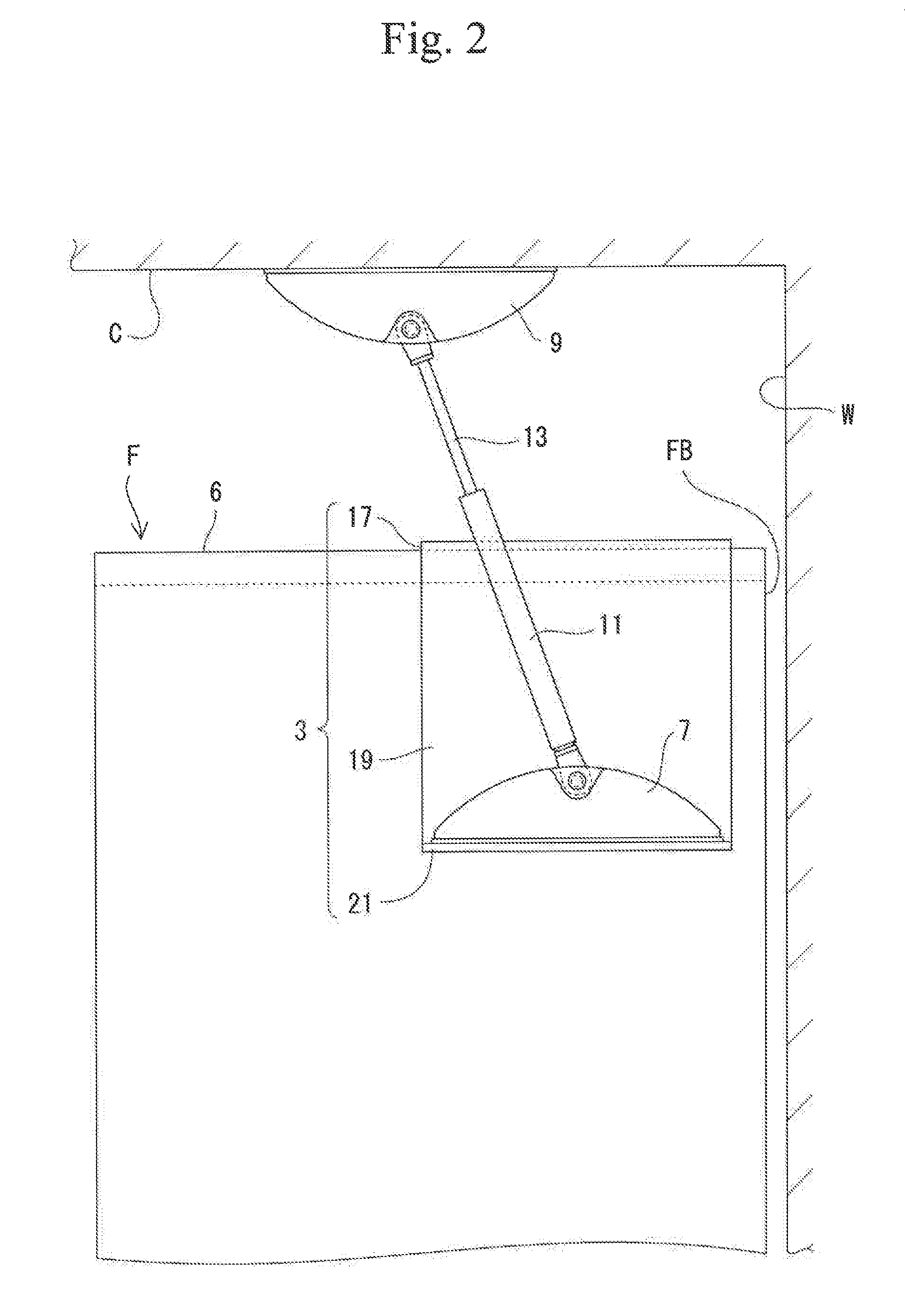
[0013] FIG. 2 is a side view of the overturn preventing device of the first embodiment;
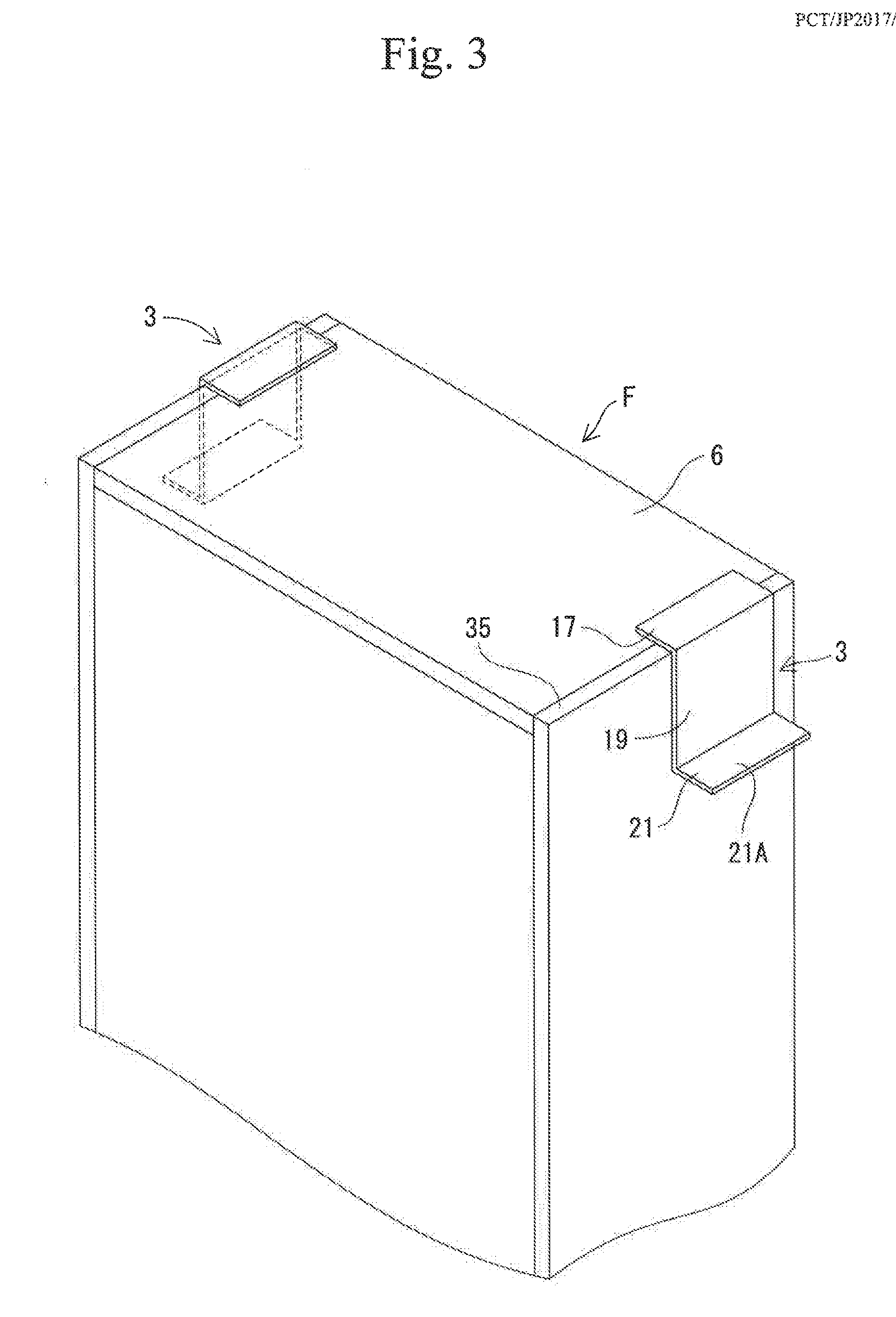
[0014] FIG. 3 is a perspective view of the overturn preventing device of the first embodiment with a bracket being attached to the furniture;
[0015] FIG. 4 is an exploded perspective view of the bracket of the overturn preventing device of a second embodiment;
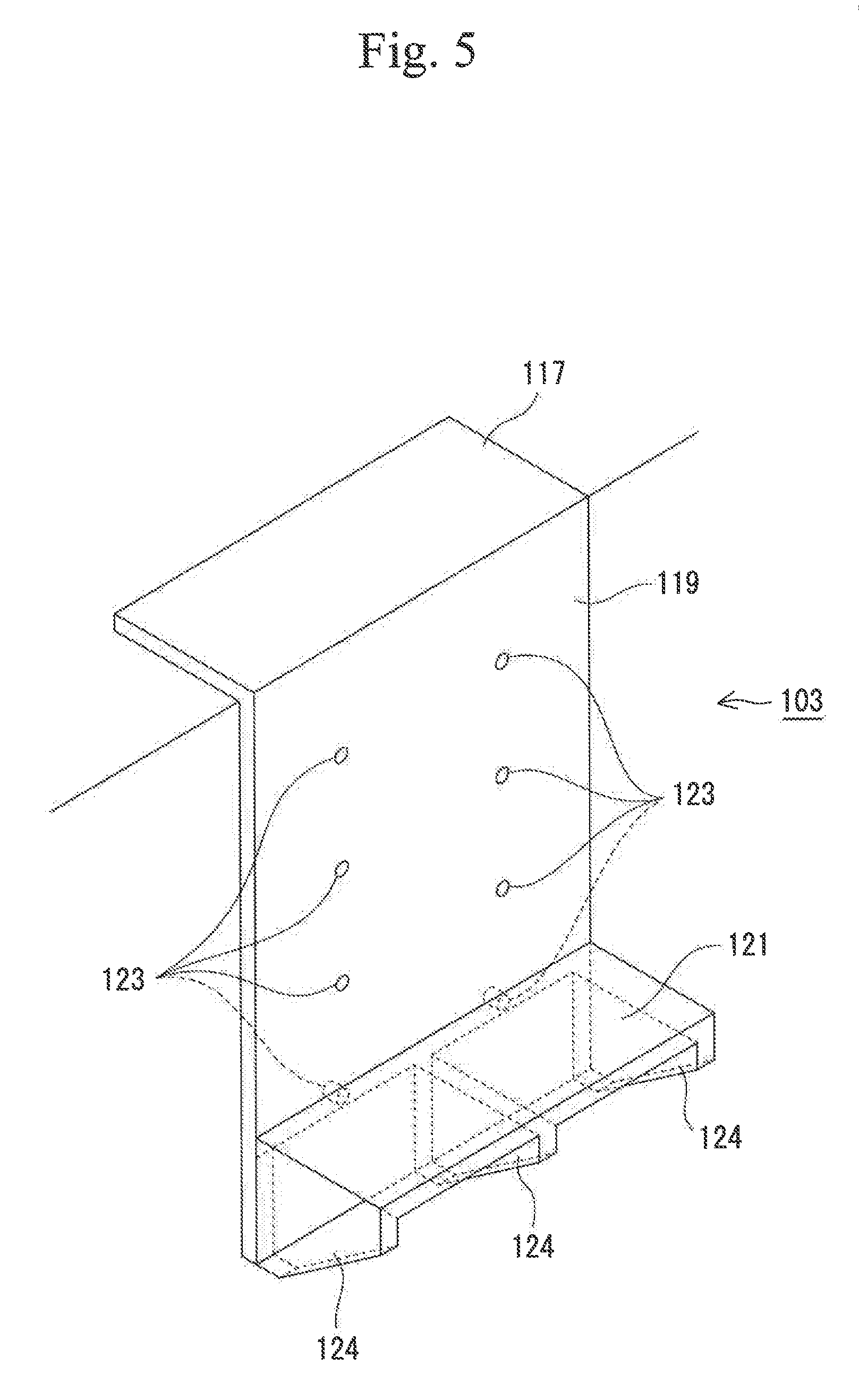
[0016] FIG. 5 is a perspective view of the bracket of the overturn preventing device of the second embodiment;
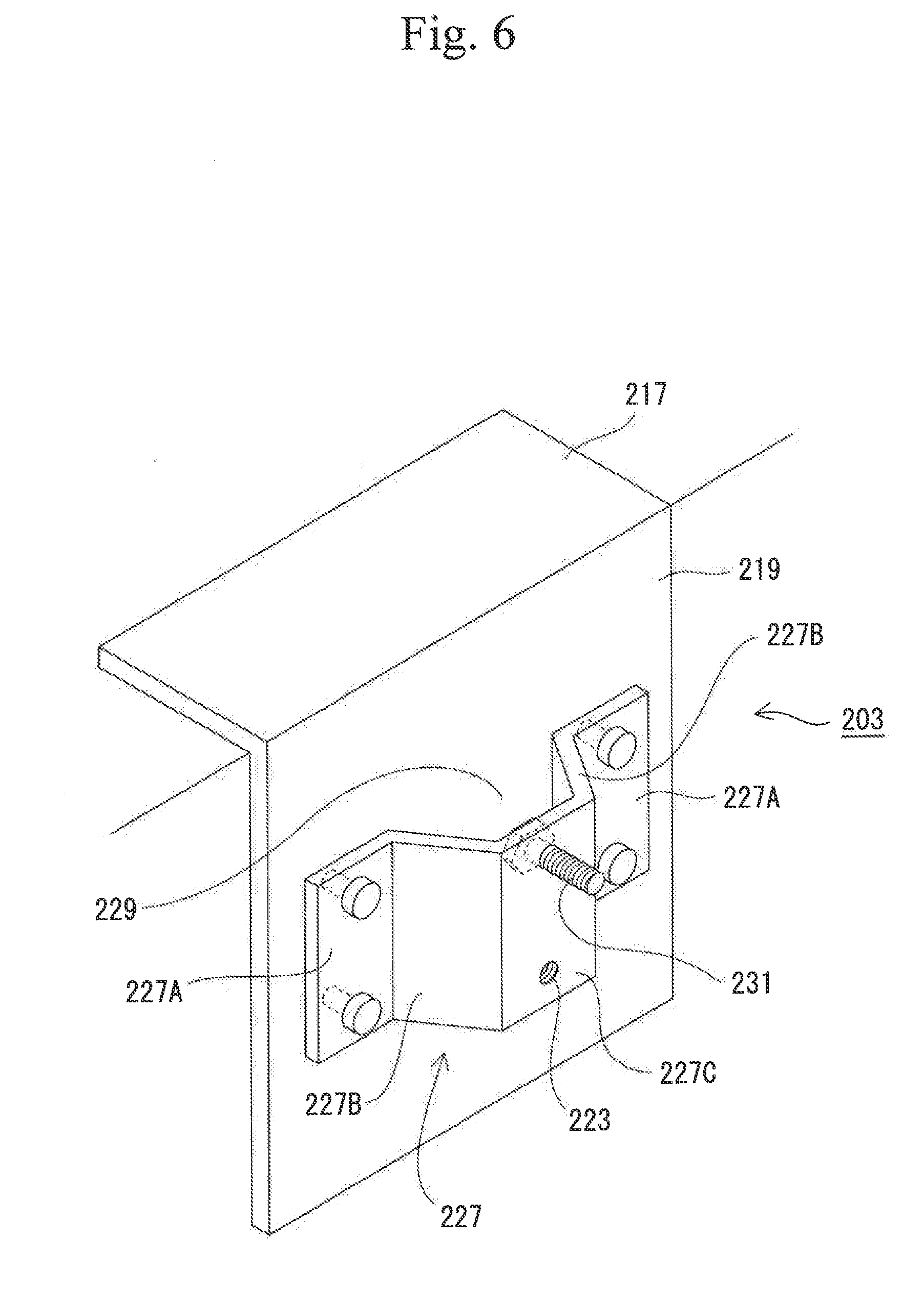
[0017] FIG. 6 is a perspective view of the bracket of the overturn preventing device of a third embodiment;
[0018] FIG. 7 is an exploded perspective view of the overturn preventing device of the third embodiment;
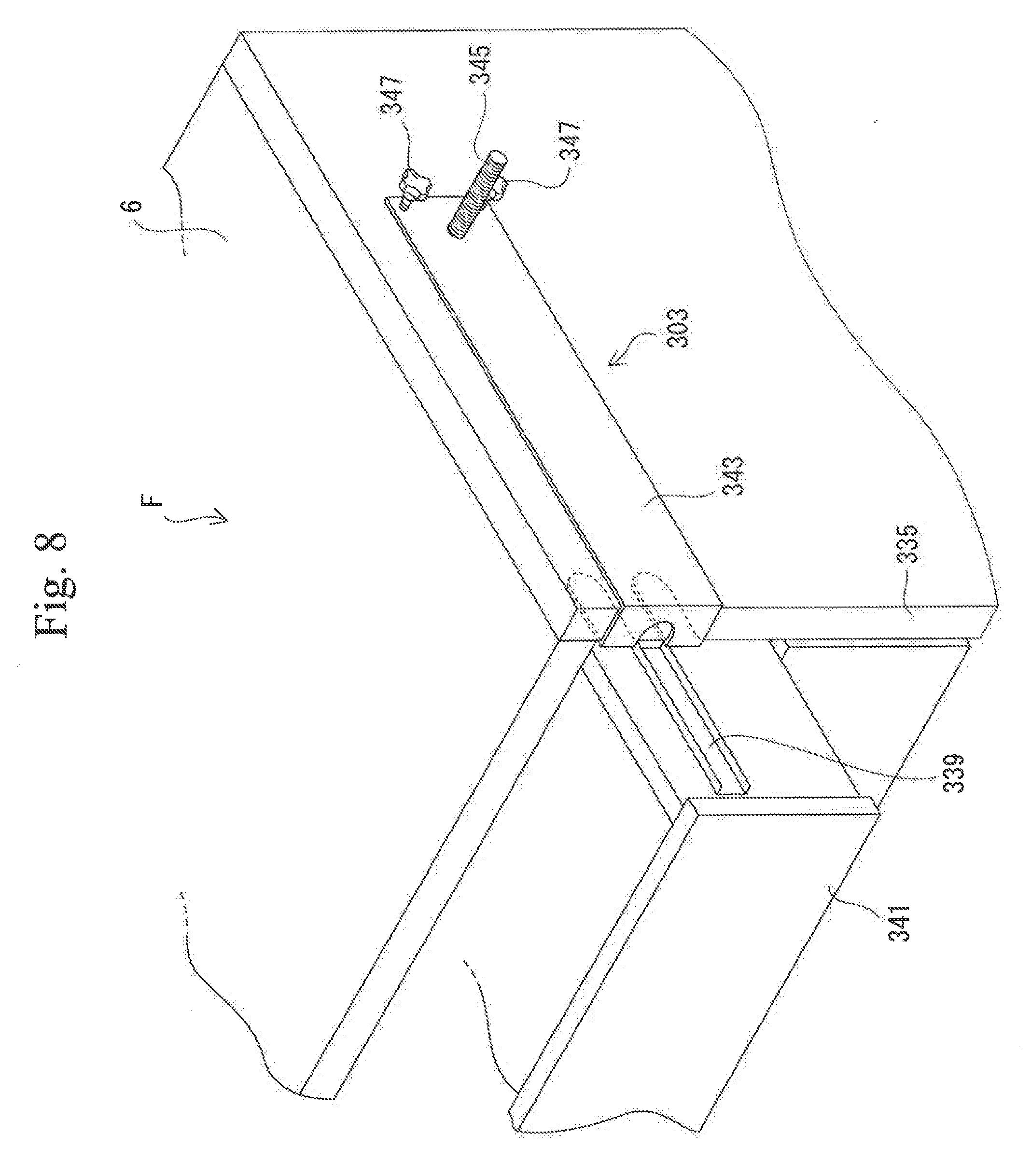
[0019] FIG. 8 is a perspective view of the bracket of the overturn preventing device of a fourth embodiment;
[0020] FIG. 9 is an exploded perspective view of the overturn preventing device of the fourth embodiment; and
[0021] FIG. 10 is a front view of an attached state of the bracket of the overturn preventing device of the fourth embodiment.
BEAT MODE FOR CARRYING OUT THE INVENTION
[0022] A first embodiment of the overturn preventing device, in accordance with the present invention will be described with reference to the drawings.
First Embodiment
[0023] As illustrated in FIG. 1, the overturn preventing device 1 of the first embodiment includes a bracket 3 made of a metal and a damper 5 (serving as a biasing member in the invention) to be supported on a lower part 21 (serving as a support part in the invention) of the bracket 3. The overturn preventing device 1 is mounted on a piece of furniture F as illustrated in FIG. 1. The furniture F is installed on a floor surface (not illustrated) serving as an installation surface while a rear surface of the furniture F is opposed to a wall surface W vertically extending from the floor surface (refer to FIG. 2). The furniture F is formed into a rectangular parallelepiped shape and has a door, drawers (neither illustrated) and the like in a front surface (a right side as viewed in FIG. 1), so that clothes, accessories and the like can be housed in the furniture F. The furniture F has the rectangular parallelepiped shape in which a width dimension thereof is larger than a depth dimension thereof. When the overturn preventing device 1 is not mounted on the furniture F, the furniture F would possibly be tilted frontward (rightward in FIG. 1) by shaking of an earthquake or the like thereby to be overturned.
[0024] In the overturn preventing device 1 of the first embodiment, a first base 7 is provided on a lower end of the damper 5, and a second base 9 is provided on an upper end of the damper 5, as illustrated in FIG. 1.
[0025] The damper 5 includes a cylinder 11, a rod guide (not illustrated), a piston (not illustrated) and a rod 13. The cylinder 11 is bottomed and has a cylindrical shape. The rod guide 12 closes an opening of the cylinder 11. The piston 14 is slidably housed in the cylinder 11. The rod 13 has a proximal end coupled to the piston. The rod 13 is inserted through the rod guide 12 and has a distal end side protruding out of the cylinder 11. The cylinder 11 encloses a hydraulic fluid and a compressed gas.
[0026] The damper 5 is a compression damper in which a damping force generated during an extending operation is smaller than a damping force generated during a contracting operation. The extending operation of the damper 5 refers to an operation which increases an amount of protrusion of the rod 13 out of the cylinder 11 (an entire length of the damper 5). The contracting operation of the damper 5 refers to an operation which reduces an amount of protrusion of the rod 13 out of the cylinder 11 (an entire length of the damper 5). Pressure of the compressed gas enclosed in the cylinder 11 works in an extension direction of the damper 5.
[0027] The following will describe a mechanism of generating a damping force by the damper 5. Since the mechanism has a known structure, diagrammatic representation is eliminated. The cylinder 11 has an interior divided by the piston into a rod side pressure chamber in which the proximal end of the rod 13 is housed and a counter-rod side pressure chamber. The piston is formed with an orifice which is a throttle valve communicating between both pressure chambers. The orifice functions as a damping force generator which applies resistance to a flow of the hydraulic fluid between the rod side pressure chamber and the counter-rod side pressure chamber with the extending/contracting operation of the damper 5. Furthermore, the piston is formed with a communication path communicating via a check valve with both pressure chambers. The check valve allows the hydraulic fluid to flow from the rod side pressure chamber to the counter-rod side pressure chamber and blocks reverse flow of the hydraulic fluid. Accordingly, the damper 5 has two flow paths of the hydraulic fluid from the rod side pressure chamber to the counter-rod side pressure chamber during the extending operation, that is, one flow path including the orifice and the other flow path including the communication path. On the other hand, the damper 5 has only one flow path of the hydraulic fluid from the counter-rod side pressure chamber to the rod side pressure chamber through the orifice during the contracting operation. Accordingly, the damping force generated by the damper 5 during the extending operation is smaller than the damping force generated by the damper 5 during the contracting operation.
[0028] A lower end of the cylinder 11 is swingably coupled to the first base 7, and an upper end of the rod 13 is swingably coupled to the second base 9.
[0029] The bracket 3 is formed by bending a metal plate. More specifically, the bracket 3 is formed into a generally Z-shape as viewed in a side view, as illustrated in FIGS. 1 to 3. The bracket 3 includes an upper part 17 (serving as an abutting part in the invention) and a midriff part 19 (serving as a middle part in the invention) and a lower part 21. The upper part 17 of the bracket 3 makes an approximately right angle to the midriff part 19 as viewed in the side view. The midriff part 19 of the bracket 3 makes an approximately right angle to the lower part 21 as viewed in the side view. The upper part 17 is formed into a plate shape extending in a horizontal direction. An underside of the upper part 17 of the bracket 3 is mounted in abutment on the top surface 6 of the furniture F. The underside of the upper part 17 may be provided with a slip preventing member having a high frictional coefficient. For example, the slip preventing member may be made of rubber or a resin material and formed with concavo-convex parts on the surface thereof. The underside of the upper part 17 is brought into face-to-face contact with the top surface 6 of the furniture F. Accordingly, load from the first base 7 is received by the upper part 17 and the top surface 6 serving as contact surfaces without concentration to a local part of the top surface 6. The midriff part 19 of the bracket 3 is formed into a plate shape extending in an approximately vertical direction. The midriff part 19 droops along a side surface of the furniture F. The lower part 21 of the bracket 3 is formed into a plate shape extending in a horizontal direction in which the lower part 21 departs from the side surface of the furniture F. The underside of the first base 7 is placed on an upper surface 21A (refer to FIG. 3) of the lower part 21 of the bracket 3. The lower part 21 has a larger area than the underside of the first base 7 so that an entire underside of the first base 7 can be placed thereon.
[0030] A mounting manner will be next described in the case where the overturn preventing device 1 is mounted on the furniture F which is placed on the floor surface with a rear surface FB of the furniture F being opposed to the wall surface W.
[0031] First, the bracket 3 is attached to a side end corner of the upper surface 6 of the furniture F. At this time, the bracket 3 is attached so that the underside of the upper part 17 thereof abuts against the top surface 6 of the furniture F. The midriff part 19 of the bracket 3 is attached so as to droop along the side surface of the furniture F. Then, the lower part 21 of the bracket 3 extends horizontally from the side surface of the furniture F.
[0032] Next, the first base 7 which is a lower end of the damper 5 is placed on the upper surface 21A of the lower part 21 of the bracket 3, and the second base 9 which is an upper end of the damper 5 is attached so as to abut against the ceiling C. At this time, it is preferable that an inclination angle of the damper 5 with respect to the vertical direction is set in a range between 15.degree. and 25.degree. so that the upper end of the damper 5 is inclined frontward. It is preferable that a pair of right and left overturn preventing devices 1 is mounted as illustrated in FIG. 1. In this case, since the furniture F is supported by the paired overturn preventing devices 1 at two positions, the furniture F is less likely to be overturned against shaking.
[0033] The bracket 3 of the overturn preventing device 1 of the embodiment has the lower part 21 which supports the first base 7 of the damper 5 at a position lower than the top surface 6 of the furniture F to be prevented from overturn. As a result, the overturn preventing device 1 can be installed even when a space between the top surface 6 of the furniture F and the ceiling C is so narrow and an installed length of the conventional overturn preventing device is too long to be mounted. Furthermore, the mounting work needs not to be carried out in the space between the top surface 6 and the ceiling C as in the conventional art but can be carried out at a lower position, with the result that mounting efficiency is high and the overturn preventing device 1 can be easily installed.
[0034] The bracket 3 includes the upper part 17 abutting against the top surface 6 of the furniture F. Accordingly, the damper 5 to which load is applied is supported via the bracket 3 on the top surface 6 of the furniture F. As illustrated in FIG. 1, the bracket 3 is disposed on the upper part of a side plate 35 of the furniture F. The side plate 35 of the furniture F generally has a high strength. Accordingly, even when the furniture F is tilted in occurrence of an earthquake and the distance between the top surface 6 of the furniture F and the ceiling C is reduced with the result that the damper 5 contracts to exert a damping force and the bracket 3 presses the side plate 35 of the top surface 6 of the furniture F, the furniture F can be prevented from overturn without being deformed.
[0035] Although the midriff part 19 of the bracket 3 droops along the side surface of the furniture F in the first embodiment, it is more preferable that the midriff part 19 is in contact with the side surface of the furniture F. The reason for this is that the bracket 3 can be kept in a more stable posture with respect to the furniture F by the face-to-face contact of the midriff part 19 and the side surface of the furniture F.
[0036] Furthermore, a mode may be employed in which a pair of brackets 3 mounted on the furniture F is coupled together.
[0037] Still furthermore, a slip preventing member having a high frictional coefficient may be provided between the midriff part 19 and the side plate 35. With this configuration, the bracket 3 becomes less slippery with respect to the furniture F, so that the positional deviation of the bracket 3 with respect to the furniture F becomes less likely to occur.
Second Embodiment
[0038] Next, the overturn preventing device of a second embodiment will be described with reference to FIGS. 4 and 5. In the overturn preventing device of the second embodiment, identical or similar parts are labeled by the same reference symbols as those in the first embodiment and the description of structure, working and advantageous effects of these parts will be eliminated. The second embodiment differs from the first embodiment in the following points.
[0039] More specifically, in the second embodiment, the bracket 103 includes the upper part 117 serving as the abutting part, the midriff part 119 serving as the middle part and the lower part 121 serving as the support part, as illustrated in FIG. 4. The lower part 121 is attachable to and detachable from the midriff part 119, and the position of the lower part 121 is changeable in the up-down direction at a plurality of positions. More specifically, the midriff part 119 of the bracket 103 is formed with a plurality of holes 123 (serving as engaged parts in the invention) located at different height positions, and protrusions 125 (serving as engaging parts in the invention) insertable into the holes 123 are provided on the lower part 121 serving as a support part of the bracket 103. The reinforcing plates 124 each of which has a substantially right triangle shape are respectively provided on both sides of the underside of the lower part 121 and the middle in the width direction. As illustrated in FIG. 5, when the lower part 121 is attached to the midriff part 119, one side of each reinforcing plate 124 abuts against the midriff part 119, whereby the load applied to the lower part can be supported.
[0040] In the second embodiment, the damper 5 having the same length can be attached by moving the lower part 121 to a plurality of positions in the up-down direction even if the height of the furniture F is different and the distance from the ceiling C is different. When the damper 5 having the same length is to be mounted, the shorter the distance between the upper surface 6 of the furniture F and the ceiling C becomes, the lower the first base 7 becomes lower than the upper surface 6 of the furniture F. In this case, the damper 5 having the same length can be mounted by selecting the lower holes 123 according to the distance and inserting the protrusions 125 into the selected holes 123 so that the lower part 121 is fixed.
[0041] In the embodiment, two holes 123 arranged transversely constitute one set and four sets of the holes 123 are formed in the up-down direction. However, the number of holes 123 constituting each set should not be particularly limited but may be one or more. Furthermore, the number of sets of the holes 123 should not be particularly limited but may be two or more.
Third Embodiment
[0042] Next, the overturn preventing device of a third embodiment will be described with reference to FIGS. 6 and 7. In the overturn preventing device of the third embodiment, identical or similar parts are labeled by the same reference symbols as those in the first embodiment and the description of structure, working and advantageous effects of these parts will be eliminated. The third embodiment differs from the first embodiment in the following points.
[0043] More specifically, in the third embodiment, the bracket 203 includes the upper part 217 and the midriff part 219 but does not have any lower part, as illustrated in FIG. 6. The bracket 203 is formed into a generally L-shape as viewed in a side view. The midriff part 219 is formed with a mountain part 227 made of metal protruding to the side of the furniture F. The mountain part 227 is formed by bending a generally rectangular metal plate and fixed to the midriff part 219 at generally rectangular shaped skirts 227A of both sides thereof. The mountain part 227 has a pair of side walls 227B bent from the respective skirts 227A at an obtuse angle and rising obliquely toward a protruding direction, and a flat peak part 227C extending from upper ends of both side walls 227B. The peak part 227C is generally formed into a vertically long rectangular shape and is substantially in parallel to the midriff part 219. The mountain part 227 has a space 229 penetrating in the up-down direction. The space 229 is formed into a generally square prism shape in which upper and lower bases thereof are formed into a generally trapezoidal shape. The peak part 227C is formed with two through holes 223 spaced in the up-down direction, and a bolt 231 is screwed through either hole 223. In the invention, the bolt 231 serves as the support part.
[0044] A cylindrical part 233 is provided on a lower end of the damper 5 as illustrated in FIG. 7. The bolt 231 inserted through either hole 223 is further inserted through the cylindrical part 233, and double nut (or lock nut) is then tightened on the bolt 231, whereby the lower end of the damper 5 is rotatably mounted on the bracket 203. In the third embodiment, even when the height of the furniture F differs from one case to another and the distance between the top surface of the furniture F and the ceiling C accordingly differs from one case to another, the damper 5 having the same length can be mounted by moving the bolt 231 to a plurality of positions in the up-down direction. In other words, when the damper 5 having the same length is to be attached, the shorter the distance between the upper surface 6 of the furniture F and the ceiling C becomes, the lower the first base 7 becomes lower than the upper surface 6 of the furniture F. Therefore, the damper 5 having the same length can be mounted by selecting one of the upper and lower holes 223 according to the position of the first base 7, inserting the bolt 231 through the selected hole 223, and further inserting the bolt 231 through the cylindrical part 233 and tightening the nut on the bolt 231.
[0045] In the embodiment, the position of the bolt 231 is easy to adjust since the operator can put one of his or her hands into the space 229 of the mountain part 227 to insert or remove the bolt 231.
[0046] Although two holes 223 are formed in the up-down direction, the number of the holes 223 should not be limited but may be two or more.
Fourth Embodiment
[0047] Next, the overturn preventing device of a fourth embodiment will be described with reference to FIGS. 8 to 10. In the overturn preventing device of the fourth embodiment, identical or similar parts are labeled by the same reference symbols as those in the first embodiment and the description of structure, working and advantageous effects of these parts will be eliminated. The fourth embodiment differs from the first embodiment in the following points.
[0048] More specifically, in the fourth embodiment, the bracket 303 clamps the side plate 335 of the furniture F at an inside and an outside thereof as illustrated in FIGS. 8 to 10. In more detail, the bracket 303 is bent into a substantially J shape. The bracket 303 is bifurcated to have distal ends 337 (serving as clamping parts in the invention). A drawer rail 339 of the furniture F is disposed between the bifurcated portions. The bracket 303 is caught on the rail 339 thereby to be prevented from falling. The distal ends 337 of the bifurcated portions are rounded into an arc shape. The distal ends 337 are inserted between the side plate 335 and the drawer 341. The bracket body 343 (serving as a body in the invention) is continuous to the distal ends 337 and is mounted so as to extend along an outer surface of the side plate 335. The bracket body 343 is formed with a bolt-shaped part 345 protruding to the side of the furniture F. Furthermore, two thumb screws 347 are attached to the bracket body 343. The bracket 343 is fixed to the side plate 335 when the thumb screws 347 are turned right. The bracket body 343 is detached from the side plate 335 when the thumb screws 347 are turned left.
[0049] The cylindrical part 233 is provided on the lower end of the damper 5. The bolt-shaped part 345 is inserted through the cylindrical part 233, and the double nut (or the lock nut) is tightened on the bolt-shaped part 345 so that the lower end of the damper 5 is rotatably mounted on the bracket body 343.
[0050] In the fourth embodiment, the inside and the outside of the side plate 335 of the furniture F can be clamped by the bracket 303. When the bracket 303 is thus configured to clamp the side plate 335 of the furniture F, it is not necessary to work between the top surface 6 of the furniture F and the ceiling C so that work efficiency is high.
[0051] Furthermore, since the bracket 303 has bifurcated distal ends 337, the bracket 303 can be fixed to the side plate 335 while escaping the rail 339 even if the drawer rail 339 protrudes.
[0052] Furthermore, since the bifurcated distal ends 337 are rounded into the arc shape, these ends can be inserted between the side plate 335 and the drawer 341 more smoothly as compared with angular distal ends.
[0053] The present invention should not be limited to the embodiments described above with reference to the drawings, but the technical scope of the invention encompasses the following embodiments, for example.
(1) Although the damper 5 is exemplified as the biasing member in the first embodiment, the biasing member should not be limited to the damper 5. A bar-shaped member to which an elastic force of a spring and the like is imparted in an extension direction may be appropriately employed. (2) Although the level of the lower part 121 serving as the support part of the bracket 103 can be changed in four stages in the second embodiment, the bracket 3 may be changeable in two, three or more stages. (3) In the second embodiment, the midriff part 119 of the bracket 103 has a plurality of holes 123 located at different height positions, and the protrusions 125 insertable into the holes 123 are provided on the lower part 121 serving as the support part of the bracket 103. However, for example, the midriff part 119 of the bracket 103 may have a plurality of protrusions located at different height positions of the midriff part 119, and the lower part 121 serving as the support part of the bracket 103 may be provided with holes into which the protrusions are insertable. (4) Although the overturn preventing device is mounted on the furniture F in the first to fourth embodiments, the overturn preventing device may be mounted on an article such as a bookshelf or a refrigerator which has a possibility of being overturned by shaking of an earthquake or the like. (5) Although two overturn preventing devices are mounted in the first to fourth embodiments, one, three or more overturn preventing devices may be mounted.
[0054] In the first embodiment, paired overturn preventing devices are mounted on the furniture placed on the floor surface with the rear surface FB thereof being opposed to the wall surface W. However, the overturn preventing devices may be mounted on a piece of furniture placed on the floor surface without being adjacent to the wall surface W, if one of the paired overturn preventing devices is mounted to be inclined in a manner such that the upper end of the damper 5 is located forward relative to the lower end, and the other overturn preventing device is mounted to be inclined in a manner such that the upper end of the damper 5 is located rearward relative to the lower end, so that the paired dampers 5 are inclined in opposite directions.
(6) Although the compression damper is used in each of the first to fourth embodiments, a two-way damper may be used as long as it exerts a predetermined damping force during the contracting operation. (7) Although the damper 5 enclosing the hydraulic fluid and the compressed gas in the cylinder 11 is used in the first to fourth embodiments, a damper enclosing another liquid may be used as long as it generates a predetermined damping force during the contracting operation. (8) In the first to fourth embodiments, the compressed gas is enclosed in the cylinder 11 so that the expansion force of the compressed gas acts in the extension direction. However, the force acting in the extension direction may be generated by another manner. (9) Although the first to fourth embodiments describe the first base 7 and second base 9 each having the specific shape, each base should not be limited to the specific shape.
EXPLANATION OF REFERENCE SYMBOLS
[0055] F . . . furniture (article), C . . . ceiling, 1 . . . overturn preventing device, 3 . . . bracket, 5 . . . damper (biasing member), 6 . . . top surface and 21 . . . lower part (support part).
* * * * *
D00000
D00001
D00002
D00003
D00004
D00005
D00006
D00007
D00008
D00009
D00010
XML
uspto.report is an independent third-party trademark research tool that is not affiliated, endorsed, or sponsored by the United States Patent and Trademark Office (USPTO) or any other governmental organization. The information provided by uspto.report is based on publicly available data at the time of writing and is intended for informational purposes only.
While we strive to provide accurate and up-to-date information, we do not guarantee the accuracy, completeness, reliability, or suitability of the information displayed on this site. The use of this site is at your own risk. Any reliance you place on such information is therefore strictly at your own risk.
All official trademark data, including owner information, should be verified by visiting the official USPTO website at www.uspto.gov. This site is not intended to replace professional legal advice and should not be used as a substitute for consulting with a legal professional who is knowledgeable about trademark law.