Extendable Table System
Schwenke; Robert
U.S. patent application number 16/247421 was filed with the patent office on 2019-05-16 for extendable table system. The applicant listed for this patent is Robert Schwenke. Invention is credited to Robert Schwenke.
| Application Number | 20190142157 16/247421 |
| Document ID | / |
| Family ID | 66432934 |
| Filed Date | 2019-05-16 |

| United States Patent Application | 20190142157 |
| Kind Code | A1 |
| Schwenke; Robert | May 16, 2019 |
EXTENDABLE TABLE SYSTEM
Abstract
The embodiments herein provide a table assembly comprising a set of tables and a plurality of extension members, each extension member configured to be inserted between two tables positioned adjacent to each other such that the extension member when inserted to be in a coplanar relationship in a horizontal plane along with adjacent tables forms an extended table system.
| Inventors: | Schwenke; Robert; (Discovery Bay, CA) | ||||||||||
| Applicant: |
|
||||||||||
|---|---|---|---|---|---|---|---|---|---|---|---|
| Family ID: | 66432934 | ||||||||||
| Appl. No.: | 16/247421 | ||||||||||
| Filed: | January 14, 2019 |
| Current U.S. Class: | 108/64 |
| Current CPC Class: | A47B 87/002 20130101; A47B 3/08 20130101; A47B 1/04 20130101; A47B 2013/024 20130101 |
| International Class: | A47B 87/00 20060101 A47B087/00; A47B 3/08 20060101 A47B003/08; A47B 1/04 20060101 A47B001/04 |
Claims
1. A convertible table system comprising: a set of tables comprising at least two tables positioned adjacent to each other; and at least one extension member comprising two parts, the extension member when inserted between the two tables positioned adjacent to each other transforms the two tables into an enlarged table system; wherein the extension member is configured for holding the two tables in coplanar relationship in a horizontal plane.
2. The system as claimed in claim 1, wherein each table in the set of tables comprises: a base for supporting the table; and a table top pivotally mounted and secured to the base at a fixed position in a horizontal plane.
3. The system as claimed in claim 1, wherein the extension member comprises at least one fastening device configured for coupling the extension member to the table tops of the adjacent tables.
4. The system as claimed in claim 1, wherein the fastening device is a clip.
5. The system as claimed in claim 1, wherein the clip is structured to form a surface between the adjacent table tops and the extension member positioned in between the table tops.
6. The system as claimed in claim 1, wherein the clip is structured to wrap about half of the table top located on either side of the extension member.
7. The system as claimed in claim 1, wherein the extension member is made of poly vinyl chloride.
8. The system as claimed in claim 1, wherein the extension member is manufactured using one of injection or molding process.
9. The system as claimed in claim 1, further comprising a metal strap hinge riveted to the edges at midpoint of the extension member.
10. The system as claimed in claim 1, wherein the metal strap hinge comprises a stainless-steel strap hinge.
Description
BACKGROUND
Technical Field
[0001] The embodiments herein generally relate to a convertible table system. More particularly, the embodiments herein describe a mechanism of converting a set of tables into an extended table system.
Description of the Related Art
[0002] The currently available mechanisms for attaching tables to obtain an extended table system include need for physical attachment to the existing tables. Such physical attachments need lot of effort in mounting for extension and dismounting for retraction. Further, seamless extension seems to be a mirage to achieve.
[0003] Hence, there is a need for providing an extended table system that is easy to extend and retract and achieves extension seamlessly.
[0004] The abovementioned shortcomings, disadvantages and problems are addressed herein and which will be understood by reading and studying the following specification.
OBJECT OF THE EMBODIMENTS HEREIN
[0005] The primary object of the embodiments herein is to provide an extendable table system.
[0006] Another object of the embodiments herein is to provide an extension member that when inserted between two tables forms an extended table system.
[0007] Yet another object of the embodiments herein is to provide an extension member that forms an extended table system in a seamless manner.
[0008] Yet another object of the embodiments herein is to provide an extendable table system that is easy to configure and retract.
[0009] These and other objects and advantages of the embodiments herein will become readily apparent from the following summary and the detailed description taken in conjunction with the accompanying drawings.
SUMMARY
[0010] The following details present a simplified summary of the embodiments herein to provide a basic understanding of the several aspects of the embodiments herein. This summary is not an extensive overview of the embodiments herein. It is not intended to identify key/critical elements of the embodiments herein or to delineate the scope of the embodiments herein. Its sole purpose is to present the concepts of the embodiments herein in a simplified form as a prelude to the more detailed description that is presented later.
[0011] The other objects and advantages of the embodiments herein will become readily apparent from the following description taken in conjunction with the accompanying drawings.
[0012] The various embodiments herein provide a table assembly comprising a set of tables and a plurality of extension members, each extension member configured to be inserted between two tables positioned adjacent to each other such that the extension member when inserted to be in a coplanar relationship in a horizontal plane along with adjacent tables forms an extended table system.
[0013] According to an embodiment herein, a convertible table system comprising a set of tables comprising at least two tables positioned adjacent to each other and at least one extension member comprising two parts, the extension member when inserted between the two tables positioned adjacent to each other transforms the two tables into an enlarged table system, wherein the extension member is configured for holding the two tables in coplanar relationship in a horizontal plane.
[0014] According to an embodiment herein, each table in the set of tables comprises a base for supporting the table and a table top pivotally mounted and secured to the base at a fixed position in a horizontal plane.
[0015] According to an embodiment herein, the extension member comprises at least one fastening device configured for coupling the extension member to the table tops of the adjacent tables.
[0016] According to an embodiment herein, the fastening device is a clip.
[0017] According to an embodiment herein, the clip is structured to form a surface between the adjacent table tops and the extension member positioned in between the table tops.
[0018] According to an embodiment herein, the clip is structured to wrap about half of the table top located on either side of the extension member.
[0019] According to an embodiment herein, the extension member is made of poly vinyl chloride.
[0020] According to an embodiment herein, the extension member is manufactured using one of injection or molding process.
[0021] According to an embodiment herein, the extendable table system further comprises a metal strap hinge riveted to the edges at midpoint of the extension member.
[0022] According to an embodiment herein, the metal strap hinge comprises a stainless steel strap hinge.
[0023] These and other aspects of the embodiments herein will be better appreciated and understood when considered in conjunction with the following description and the accompanying drawings. It should be understood, however, that the following descriptions, while indicating preferred embodiments and numerous specific details thereof, are given by way of illustration and not of limitation. Many changes and modifications may be made within the scope of the embodiments herein without departing from the spirit thereof, and the embodiments herein include all such modifications.
BRIEF DESCRIPTION OF THE DRAWINGS
[0024] The other objects features and advantages will occur to those skilled in the art from the following description of the preferred embodiment and the accompanying drawings in which:
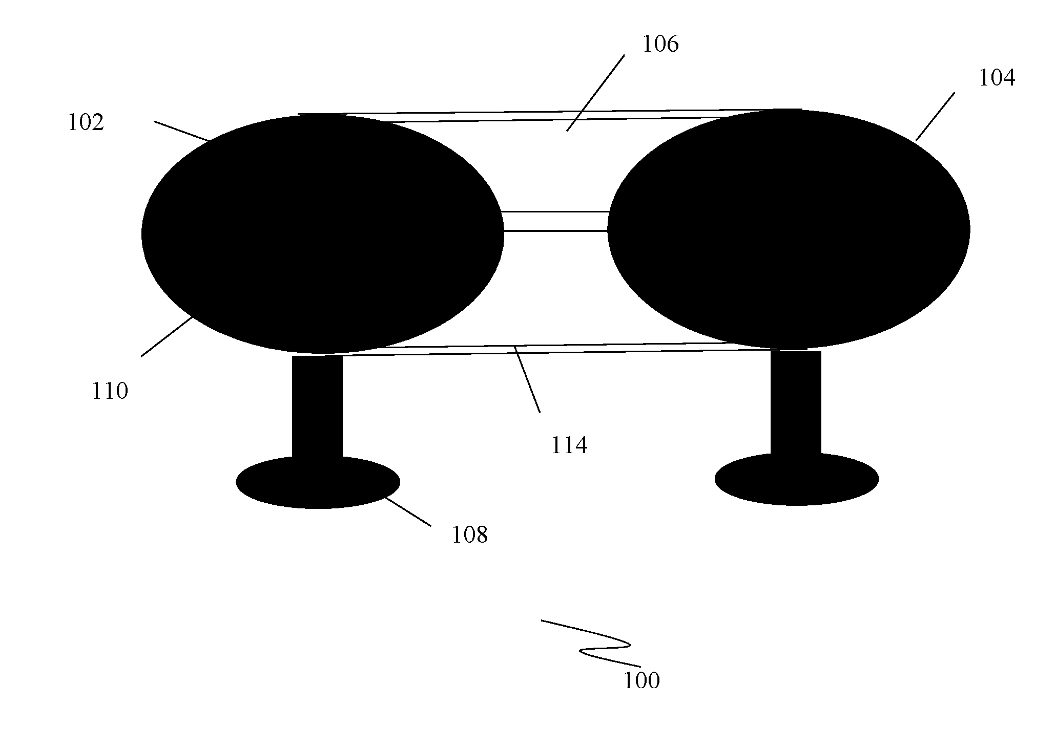
[0025] FIG. 1 illustrates a perspective view of an extendable table system, according to an embodiment herein.
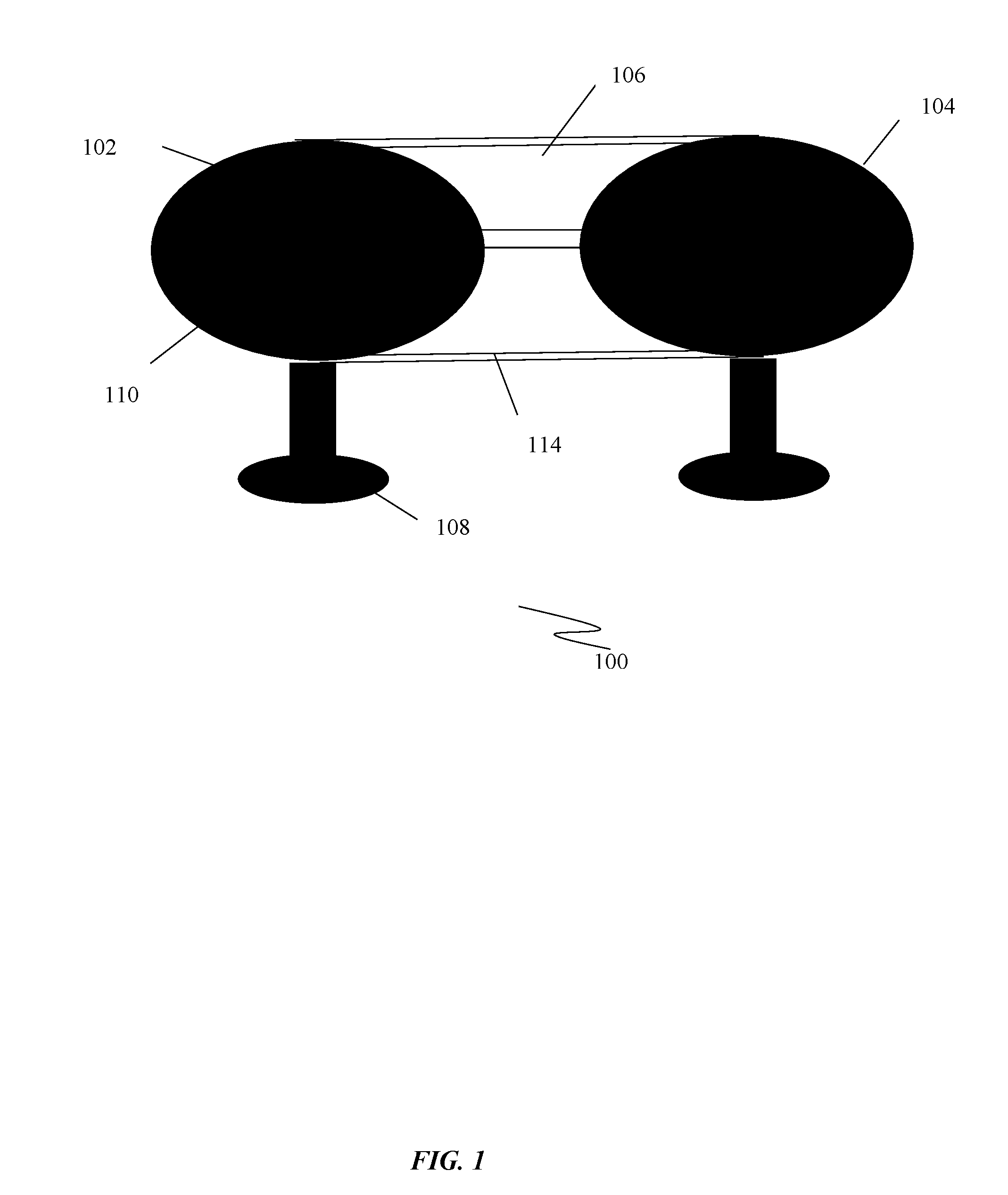
[0026] FIG. 2 illustrates a top view of the extendable table system shown in FIG. 1, according to an embodiment herein.
[0027] Although the specific features of the embodiments herein are shown in some drawings and not in others. This is done for convenience only as each feature may be combined with any or all of the other features in accordance with the embodiment herein.
DETAILED DESCRIPTION OF THE EMBODIMENTS HEREIN
[0028] The embodiments herein and the various features and advantageous details thereof are explained more fully with reference to the non-limiting embodiments that are illustrated in the accompanying drawings and detailed in the following description. Descriptions of well-known components and processing techniques are omitted so as to not unnecessarily obscure the embodiments herein. The examples used herein are intended merely to facilitate an understanding of ways in which the embodiments herein may be practiced and to further enable those of skill in the art to practice the embodiments herein. Accordingly, the examples should not be construed as limiting the scope of the embodiments herein.
[0029] In the following detailed description, a reference is made to the accompanying drawings that form a part hereof, and in which the specific embodiments that may be practiced is shown by way of illustration. The embodiments are described in sufficient detail to enable those skilled in the art to practice the embodiments and it is to be understood that the logical, mechanical and other changes may be made without departing from the scope of the embodiments. The following detailed description is therefore not to be taken in a limiting sense.
[0030] The various embodiments herein provide a table assembly comprising a set of tables and a plurality of extension members, each extension member configured to be inserted between two tables positioned adjacent to each other such that the extension member when inserted to be in a coplanar relationship in a horizontal plane along with adjacent tables forms an extended table system.
[0031] The general purpose of this invention is to provide "extension members". Each extension members is a two part structure, which folds out to attach/join two tables to get one long table for a bigger group. The "extension members" are supported by the table tops with fastening members such as clips. The clips are shaped to form a surface between the table and the extension members. The invention eliminates the need for any physical attachment to the existing tables due to the shape of the table insert wrapping around half of the table on each side and the weight of the table insert is enough to hold the same in place.
[0032] Accordingly, in one embodiment, as shown in FIG. 1 and FIG. 2, an extendable table system is disclosed. The extendable table system comprises a set of tables 102 and 104 comprising at least two tables 102 and 104 positioned adjacent to each other and at least one extension member 106 comprising two parts, the extension member 106 when inserted between the two tables 102 and 104 positioned adjacent to each other transforms the two tables 102 and 104 into an enlarged table system. Further, the extension member 106 is configured for holding the two tables 102 and 104 in coplanar relationship in a horizontal plane.
[0033] Each table in the set of tables 102 and 104 comprises a base 108 for supporting the table; and a table top 110 pivotally mounted and secured to the base 108 at a fixed position in a horizontal plane.
[0034] The extension member 106 is circumferentially disposed to the table top 110s of each of the tables 102 and 104 positioned adjacent to the extension member 106.
[0035] The extension member 106 comprises at least one fastening device 112 configured for coupling the extension member 106 to the table top 110s of the adjacent tables 102 and 104. In one exemplary embodiment, the fastening device 112 is a clip. The clip is structured to wrap about half of the table top 110 located on either side of the extension member 106 so as to form a co-planar horizontal surface between the adjacent table top 110s and the extension member 106 positioned in between the table top 110s.
[0036] The clips 112 are fabricated from stainless steel. In one exemplary embodiment, each clip is two inches wide and extending out onto the table top 110 and made to wrap around the edge of the table system 100. Each clip is attached by rivets in order to secure the position.
[0037] In one exemplary embodiment, the extension member 106 is made of poly vinyl chloride that is manufactured using one of injection or molding process. The molded or injected plastic used for fabricating the extension member 106 enhances the durability and portability of the extendable table system.
[0038] The system further comprises a metal strap hinge 114 riveted to the edges at midpoint of the extension member 106. In one exemplary embodiment, the metal strap hinge 114 comprises a stainless-steel strap hinge 114. Skilled artisans shall however appreciate that other metals suitable for the application may also be employed.
[0039] In one exemplary embodiment, the two parts of the table system 100 are connected with a twelve-inch-long stainless-steel strap hinge 114 riveted to the edges at midpoint of the table system 100 for flexibility of installation and storage.
[0040] The advantages of the embodiments disclosed herein comprise an easy to extend and retract extended table system 100 that achieves extension seamlessly. Further, molded or injected plastic used for fabricating the extension member 106 enhances the durability and portability of the extendable table system. The stainless-steel strap hinge 114 riveted to the edges at midpoint of the table system 100 provides flexibility for installation and storage.
[0041] The foregoing description of the specific embodiments will so fully reveal the general nature of the embodiments herein that others can, by applying current knowledge, readily modify and/or adapt for various applications such specific embodiments without departing from the generic concept, and, therefore, such adaptations and modifications should and are intended to be comprehended within the meaning and range of equivalents of the disclosed embodiments. It is to be understood that the phraseology or terminology employed herein is for the purpose of description and not of limitation. Therefore, while the embodiments herein have been described in terms of preferred embodiments, those skilled in the art will recognize that the embodiments herein can be practiced with modification within the spirit and scope of the appended claims.
[0042] Although the embodiments herein are described with various specific embodiments, it will be obvious for a person skilled in the art to practice the invention with modifications. However, all such modifications are deemed to be within the scope of the appended claims.
[0043] It is also to be understood that the following claims are intended to cover all of the generic and specific features of the embodiments described herein and all the statements of the scope of the embodiments which as a matter of language might be said to fall there between.
* * * * *
D00000
D00001
D00002
XML
uspto.report is an independent third-party trademark research tool that is not affiliated, endorsed, or sponsored by the United States Patent and Trademark Office (USPTO) or any other governmental organization. The information provided by uspto.report is based on publicly available data at the time of writing and is intended for informational purposes only.
While we strive to provide accurate and up-to-date information, we do not guarantee the accuracy, completeness, reliability, or suitability of the information displayed on this site. The use of this site is at your own risk. Any reliance you place on such information is therefore strictly at your own risk.
All official trademark data, including owner information, should be verified by visiting the official USPTO website at www.uspto.gov. This site is not intended to replace professional legal advice and should not be used as a substitute for consulting with a legal professional who is knowledgeable about trademark law.