Utility Cap and Utility Cap Reinforcing Member
Hardy; Christopher
U.S. patent application number 15/813291 was filed with the patent office on 2019-05-16 for utility cap and utility cap reinforcing member. The applicant listed for this patent is Christopher Hardy. Invention is credited to Christopher Hardy.
| Application Number | 20190142093 15/813291 |
| Document ID | / |
| Family ID | 66431546 |
| Filed Date | 2019-05-16 |


| United States Patent Application | 20190142093 |
| Kind Code | A1 |
| Hardy; Christopher | May 16, 2019 |
Utility Cap and Utility Cap Reinforcing Member
Abstract
A utility cap and utility cap reinforcement member is provided. The utility cap has a number of sidewalls forming a perimeter and a visor attached to a front side or a back side of the crown. The utility cap reinforcement member includes sections in an end-to-end arrangement on a single plane. The utility cap reinforcement member is adapted to be positioned within the utility cap along the perimeter, wherein the utility cap reinforcement member stiffens an appearance and a rigidity of the perimeter. In one embodiment, the utility cap reinforcement member forms a closed loop. In an alternative embodiment, the utility cap reinforcement member includes a gap that forms an open loop.
| Inventors: | Hardy; Christopher; (La Mesa, CA) | ||||||||||
| Applicant: |
|
||||||||||
|---|---|---|---|---|---|---|---|---|---|---|---|
| Family ID: | 66431546 | ||||||||||
| Appl. No.: | 15/813291 | ||||||||||
| Filed: | November 15, 2017 |
| Current U.S. Class: | 2/175.4 |
| Current CPC Class: | A42B 1/02 20130101; A42B 1/002 20130101; A42B 1/062 20130101 |
| International Class: | A42B 1/00 20060101 A42B001/00; A42B 1/02 20060101 A42B001/02 |
Claims
1) A utility cap reinforcement member, comprising: a plurality of sections in an end-to-end arrangement wherein the utility cap reinforcement member is configured to be disposed within an interior volume of a utility cap, wherein each of the plurality of sections are configured to provide support to a perimeter of the utility cap, wherein the utility cap reinforcement member stiffens an appearance and a rigidity of the perimeter.
2) The utility cap reinforcement member of claim 1, wherein the utility cap reinforcement member is dimensioned and biased to impart an outward force to the perimeter of the utility cap.
3) The utility cap reinforcement member of claim 1, wherein the plurality of sections include eight sections forming a continuous loop.
4) The utility cap reinforcement member of claim 1, wherein the plurality of sections include eight sections and a gap forming an open loop.
5) The utility cap reinforcement member of claim 1, wherein the circumference of the plurality of sections is greater than the circumference of the perimeter of the utility cap.
6) The utility cap reinforcement member of claim 1, wherein the plurality of sections comprises tubular metal wire.
7) The utility cap reinforcement member of claim 1, wherein adjacent sections of the plurality of sections forms an interior angle, wherein each interior angle is between 120 degrees and 150 degrees.
8) A utility cap having a utility cap reinforcement member, comprising: a crown including a plurality of sidewalls forming a perimeter; a visor attached to a front side or a back side of the crown; the utility cap reinforcement member disposed within the crown; wherein the utility cap reinforcement member comprising a plurality of sections in an end-to-end arrangement; wherein the plurality of sections are configured to provide support to the perimeter, wherein the utility cap reinforcement member stiffens an appearance and a rigidity of the perimeter.
Description
BACKGROUND OF THE INVENTION
Field of the Invention
[0001] The present invention relates to a utility cap reinforcing member. More specifically, the present invention provides a utility cap reinforcing member including a plurality of sections in linear arrangement forming interior angles, wherein the utility cap reinforcement member is configured to be positioned and/or inserted within a utility cap. Each of the plurality of sections are configured to provide support to the perimeter of the utility cap, such that the perimeter and sidewalls are stiff and appear stiff.
[0002] Organizations such as the military, police, and emergency services utilize strict guidelines and dress codes for proper attire, including the shape of the caps. Typically, these caps have a crown forming points around the perimeter. However, these points can deform over time if not properly maintained, leading to a sloppy appearance and possible noncompliance with dress codes.
[0003] Devices have been disclosed in the known art that relate to a utility cap reinforcing member. These include devices that have been patented and published in patent application publications. These devices in the known art have several known drawbacks. For example, a shaper or former may have an elastic band that stretches over the cap to retail the shape of the cap. However, these shapers can damage the cap from excessive stretching and may require constant adjustments.
[0004] In light of the devices disclosed in the known art, it is submitted that the present invention substantially diverges in design elements from the devices in the known art and consequently it is clear that there is a need in the art for an improvement to existing utility cap reinforcing member devices. In this regard the instant invention substantially fulfills these needs.
SUMMARY OF THE INVENTION
[0005] In view of the foregoing disadvantages inherent in the known types of utility cap reinforcing member now present in the art, the present invention provides a new utility cap reinforcing member wherein the same can be utilized for providing convenience for the user when wearing a utility cap that is required to conform with certain dress codes.
[0006] It is therefore an object of the present invention to provide a new and improved a utility cap reinforcing member comprising a plurality of sections in linear arrangement, wherein the utility cap reinforcement member is configured to be positioned and/or inserted within a utility cap. Each of the plurality of sections are configured to provide support to the perimeter of the utility cap, such that the perimeter points and edges are stiff.
[0007] It is another object of the present invention to provide a utility cap reinforcing member that can be quickly and easily reshape a cap without stretching or damaging the cap.
[0008] Another object of the present invention is to provide a utility cap reinforcing member that can be removed from the cap for cleaning or transporting.
[0009] Yet another object of the present invention is to provide a utility cap reinforcing member that protects the cap and shapes the crown of the hat during use.
[0010] Another object of the present invention is to provide a utility cap reinforcing member that may be readily fabricated from materials that permit relative economy and are commensurate with durability.
[0011] Other objects, features and advantages of the present invention will become apparent from the following detailed description taken in conjunction with the accompanying drawings.
BRIEF DESCRIPTIONS OF THE DRAWINGS
[0012] Although the characteristic features of this invention will be particularly pointed out in the claims, the invention itself and manner in which it may be made and used may be better understood after a review of the following description, taken in connection with the accompanying drawings wherein like numeral annotations are provided throughout.
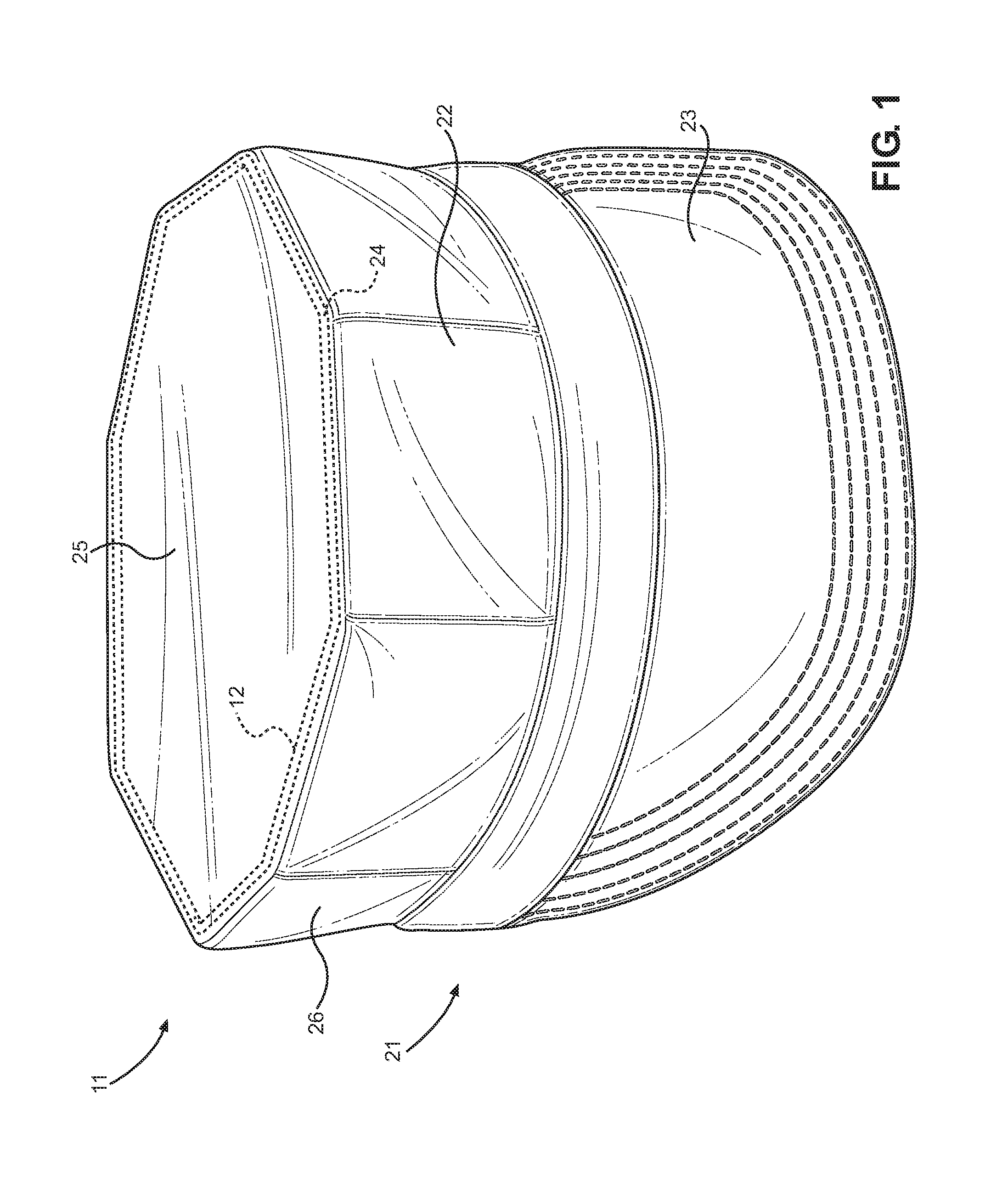
[0013] FIG. 1 shows a perspective view of the utility cap with the utility cap reinforcing member.
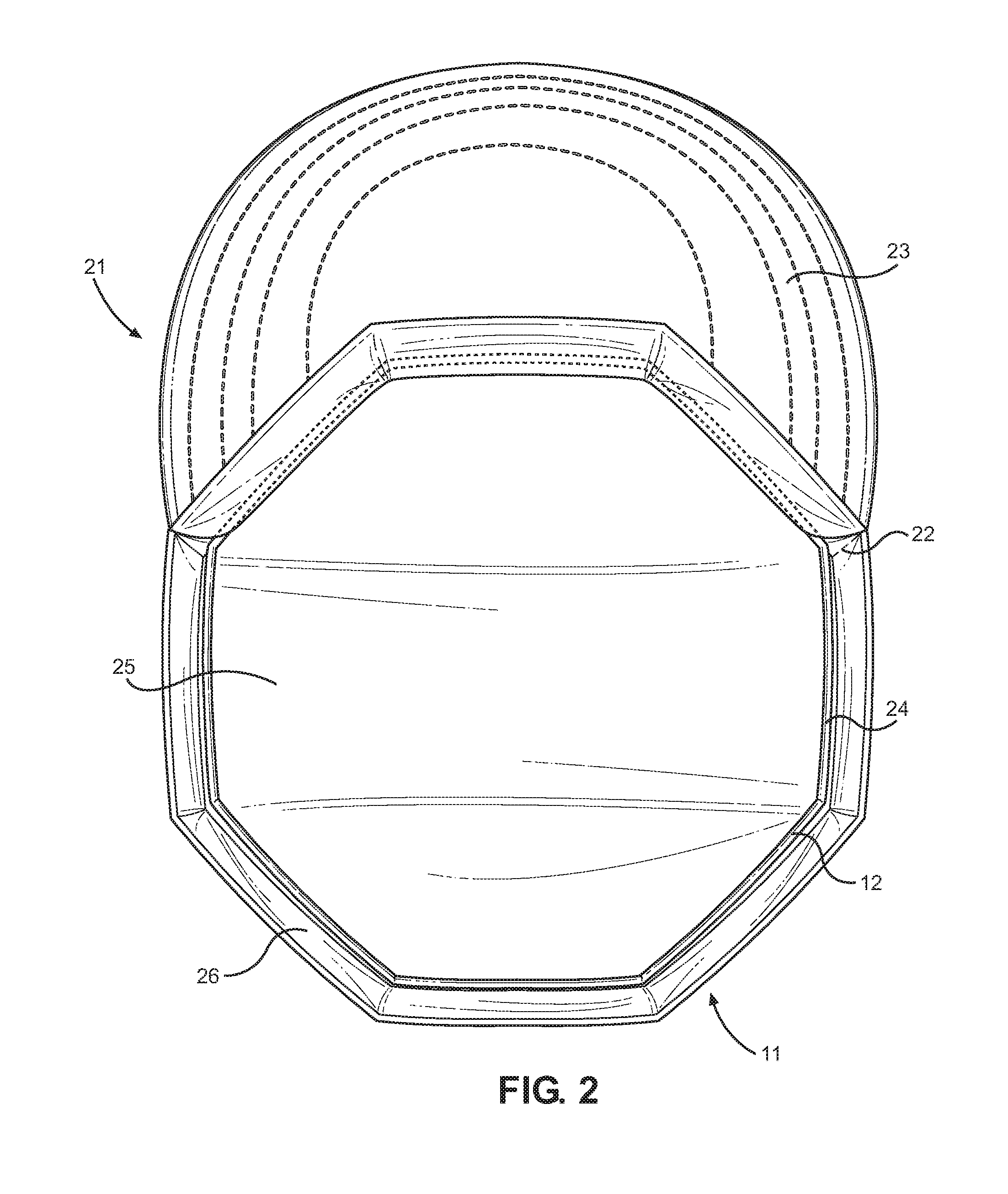
[0014] FIG. 2 shows an underside view of the utility cap with the utility cap reinforcing member.
[0015] FIG. 3 shows an overhead view of one embodiment of the utility cap reinforcing member.
[0016] FIG. 4 shows an overhead view of an alternative embodiment of the utility cap reinforcing member.
DETAILED DESCRIPTION OF THE INVENTION
[0017] Reference is made herein to the attached drawings. Like reference numerals are used throughout the drawings to depict like or similar elements of the utility cap reinforcing member. For the purposes of presenting a brief and clear description of the present invention, the preferred embodiment will be discussed as used for keeping the shape of utility caps. The figures are intended for representative purposes only and should not be considered to be limiting in any respect.
[0018] Referring to FIGS. 1 and 2, there is shown a perspective view of the utility cap with the utility cap reinforcing member, and an underside view of the utility cap with the utility cap reinforcing member, respectively. The utility cap reinforcement member 11 is configured to be positioned within or inserted within a utility cap 21, so as to provide support to the perimeter of the utility cap 21. The utility cap reinforcing member 11 provides for a utility cap 21 to maintain a desired shape that aesthetically looks clean. The utility cap reinforcement member 11 includes a plurality of sections 12 disposed in a linear arrangement along a same plane forming interior angles between each section 12. Herein, "linear arrangement" is synonymous with "end-to-end arrangement" which refers to a first end of a first section of the plurality of sections 12 affixed to a second end of a second section of the plurality of sections 12.
[0019] In the shown embodiment, utility cap reinforcement member 11 is disposed within an interior volume of the utility cap 21, and flush therewith. The utility cap 21 comprises a crown 22 affixed to a visor 23, wherein the visor extends outwardly from a lower end of the crown 22. The visor 23 includes a generally planar member that is dimensioned to cover a face of a user wearing the utility cap 21. The crown 22 comprises a plurality of sidewalls 26 that extend vertically from the visor 23 disposed on the lower end. An upper panel 25 covers the upper end of the crown 22, opposite the visor 23. The upper panel 25 joins each of the plurality of sidewalls 26 at an upper perimeter 24. The perimeter 24 is an edge formed by each of the sidewalls 26 and the upper panel 25.
[0020] In one embodiment, the utility cap reinforcing member 11 is selectively positioned within the crown 22 of the utility cap 21 so as to be disposed adjacent the perimeter 24. The utility cap reinforcing member 11 comprises a material having properties that stiffen the appearance and the rigidity of the perimeter 25. In this way, the utility cap reinforcing member 11 provides actual resistance to deformation of the perimeter 24, and gives an aesthetically clean look. The utility cap reinforcing member 11 is further dimensioned to have a circumference to be equal or greater than the circumference of the perimeter 24. Thus, the utility cap reinforcement member is dimensioned and, in some embodiments, biased to impart an outward force to the perimeter of the utility cap.
[0021] In one exemplary use, the utility cap reinforcing member 11 allows each sidewall 26 of the utility cap 21, commonly known as an 8-point utility cap as shown in FIGS. 1 and 2, to form generally flat sidewalls 26 on the crown 22 and to form angles between adjacent sidewalls 26 having equal degree amounts.
[0022] Referring to FIGS. 3 and 4, there is shown an overhead view of one embodiment of the utility cap reinforcing member and an overhead view of an alternative embodiment of the utility cap reinforcing member, respectively. The utility cap reinforcing member 11 comprises a plurality of sections 12 in linear arrangement integrally formed and disposed on a same plane. The plurality of sections 12 form interior angles 13 that may range from between 120 and 150 degrees. In an alternative embodiment, the interior angles 13 may have any suitable angle configured to causes the perimeter of the utility cap to be or appear stiff. Additionally, in the shown embodiment of FIG. 3, the sections 12 are tubular members have the same dimensions and form a continuous, closed loop. However, in alternative embodiments, the dimensions of each of the sections 12 may vary in relationship with the corresponding utility cap.
[0023] In the shown embodiment of FIG. 4, a gap 15 disposed between two of the sections of the plurality of sections 12 form an open loop. Further, one or more of the plurality of sections 12 are curved sections 12A that are biased outward from a center point of the utility cap reinforcing member 11. The center point is disposed generally equidistant from a midpoint of each of the plurality of sections 12 and on a same plane thereof. The curved sections 12A with outward bias provide additional stiffness and provide for an aesthetically clean look in certain utility caps with additional rigidity.
[0024] It is therefore submitted that the instant invention has been shown and described in what is considered to be the most practical and preferred embodiments. It is recognized, however, that departures may be made within the scope of the invention and that obvious modifications will occur to a person skilled in the art. With respect to the above description then, it is to be realized that the optimum dimensional relationships for the parts of the invention, to include variations in size, materials, shape, form, function and manner of operation, assembly and use, are deemed readily apparent and obvious to one skilled in the art, and all equivalent relationships to those illustrated in the drawings and described in the specification are intended to be encompassed by the present invention.
[0025] Therefore, the foregoing is considered as illustrative only of the principles of the invention. Further, since numerous modifications and changes will readily occur to those skilled in the art, it is not desired to limit the invention to the exact construction and operation shown and described, and accordingly, all suitable modifications and equivalents may be resorted to, falling within the scope of the invention.
* * * * *
D00000
D00001
D00002
D00003
XML
uspto.report is an independent third-party trademark research tool that is not affiliated, endorsed, or sponsored by the United States Patent and Trademark Office (USPTO) or any other governmental organization. The information provided by uspto.report is based on publicly available data at the time of writing and is intended for informational purposes only.
While we strive to provide accurate and up-to-date information, we do not guarantee the accuracy, completeness, reliability, or suitability of the information displayed on this site. The use of this site is at your own risk. Any reliance you place on such information is therefore strictly at your own risk.
All official trademark data, including owner information, should be verified by visiting the official USPTO website at www.uspto.gov. This site is not intended to replace professional legal advice and should not be used as a substitute for consulting with a legal professional who is knowledgeable about trademark law.