Ergonomic Sleeve Harness And Fasteners
WILSON; Justin Matthew ; et al.
U.S. patent application number 16/188571 was filed with the patent office on 2019-05-16 for ergonomic sleeve harness and fasteners. The applicant listed for this patent is HONEYWELL INTERNATIONAL INC.. Invention is credited to Prashant VERMA, Justin Matthew WILSON.
| Application Number | 20190142085 16/188571 |
| Document ID | / |
| Family ID | 66432894 |
| Filed Date | 2019-05-16 |

| United States Patent Application | 20190142085 |
| Kind Code | A1 |
| WILSON; Justin Matthew ; et al. | May 16, 2019 |
ERGONOMIC SLEEVE HARNESS AND FASTENERS
Abstract
A harness (10) is provided for securing a pair of electrical insulating sleeves (12) to a user (16) and includes a pair of shoulder straps (18), each shoulder strap (18) having a middle portion (20) extending between opposite end portions (22,24), and each middle portion (20) including an array of fastener receiving openings (26). Each fastener receiving opening (26) is configured to receive a fastener (28) for attaching an insulating sleeve (12). An adjustable chest strap (32) is engaged with each of the opposite end portions (22,24) of the shoulder straps (18) and is configured to extend around the torso (14) of a user (16) to secure the harness (10) to a user (16). A shoulder adjustment strap (50) extends between the shoulder straps (18) to be located behind the neck of a user (16) when the harness (10) is worn by a user (16) and is configured to provide adjustment of the middle portions (20) relative to each other.
| Inventors: | WILSON; Justin Matthew; (Morris Plains, NJ) ; VERMA; Prashant; (Morris Plains, NJ) | ||||||||||
| Applicant: |
|
||||||||||
|---|---|---|---|---|---|---|---|---|---|---|---|
| Family ID: | 66432894 | ||||||||||
| Appl. No.: | 16/188571 | ||||||||||
| Filed: | November 13, 2018 |
| Current U.S. Class: | 2/328 |
| Current CPC Class: | A41D 13/008 20130101; A41D 27/10 20130101; A41D 13/0568 20130101; A41D 2600/20 20130101; A41D 13/08 20130101 |
| International Class: | A41D 13/05 20060101 A41D013/05; A41D 13/008 20060101 A41D013/008; A41D 13/08 20060101 A41D013/08 |
Foreign Application Data
| Date | Code | Application Number |
|---|---|---|
| Nov 13, 2017 | IN | 201711040388 |
Claims
1. A harness for securing a pair of electrical insulating sleeves to a user, the harness comprising: a pair of shoulder straps, each shoulder strap having a middle portion extending between opposite end portions, each middle portion including an array of fastener receiving openings, each fastener receiving opening configured to receive a fastener for attaching an insulating sleeve; an adjustable chest strap engaged with each of the opposite end portions of the shoulder straps and configured to extend around the torso of a user to secure the harness to a user; and a shoulder adjustment strap extending between the shoulder straps to be located behind the neck of a user when the harness is worn by a user and configured to provide adjustment of the middle portions relative to each other.
2. The harness of claim 1 wherein each of the fastener receiving openings is defined by a grommet.
3. The harness of claim 1 wherein the fastener receiving openings in each shoulder strap are located to provide at least two different positions for securing an insulating sleeve to the shoulder strap.
4. The harness of claim 1 further comprising a releasable buckle fixed to opposite ends of the adjustable chest strap to allow the opposite ends to be selectively connected and disconnected.
5. The harness of claim 1 wherein the adjustable chest strap comprises a length of webbing.
6. The harness of claim 1 wherein each of the opposite end portions includes a loop through which the adjustable chest strap extends.
7. The harness of claim 1 wherein the shoulder adjustment strap has a first end fixed to one of the shoulder straps and a second end fixed to the other shoulder strap.
8. The harness of claim 7 wherein the shoulder adjustment strap includes third and fourth ends that are engaged with a strap adjuster.
9. The harness of claim 1 wherein each shoulder strap is multi-layer construction.
10. The harness of claim 1 wherein each shoulder strap comprises layer of foam sandwiched between two fabric layers.
11. The harness of claim 10 wherein the layer of foam comprises a closed cell foam.
12. The harness of claim 10 wherein one of the fabric layers comprises a mesh fabric.
13. The harness of claim 1 wherein each middle portion has a first concave peripheral edge facing the other middle portion and a second concave peripheral edge facing away from the other middle portion when the harness is worn by a user.
14. The harness of claim 1 wherein each end portion of each shoulder strap has a convex peripheral edge and a concave peripheral edge facing in opposite directions.
15. The harness of claim 1 wherein each shoulder strap has a convex peripheral edge adjacent the fastener receiving openings.
16. The harness of claim 1 further comprising four releasable fasteners, each fastener received in a corresponding one of the fastener receiving openings.
17. The harness of claim 1 wherein each releasable fastener comprises a base member and a clip member, each base member having a base portion and a post extending from the base member, and each clip member having a relief that is configured for snap fit engagement with the post.
18. The harness of claim 17 wherein each relief of each fastener comprises a concave surface sized for snap fit engagement with a convex surface of the post of the base member of the fastener.
19. The harness of claim 18 wherein the convex surface of each post is defined by an annular groove located in an end portion of the post.
20. The harness of claim 19 wherein each clip member has a slot that extends from an edge of the clip member to the relief.
Description
CROSS-REFERENCE TO RELATED APPLICATIONS
[0001] This application claims the benefit of India Patent Application No. 201711040388 filed on Nov. 13, 2017, the disclosure of which is herein incorporated by reference in its entirety.
FIELD
[0002] This disclosure relates to electrical insulating sleeves worn by linemen and other users who work in proximity to power lines and other high power electrical equipment.
BACKGROUND
[0003] The current method for wearing electrical insulating sleeves consists of using either a rubber harness or set of straps with a choice of two buttons. This approach creates three main problem areas for the end user. The three main problem areas include adjustability, wear consistency and robustness.
[0004] Adjustability in the current designs are limited to a selected number of position changes that effectively raise or lower a sleeve on the arm. While this allows adjustability to various body builds, there is no means for fine tuning when other garments are being worn. Jackets, fall protection harnesses, etc. create a need for further adjustability.
[0005] Along with adjustability, the current designs do not stay in place as expected while being worn. The rubber sleeve harness and straps tend to ride up around the neck area during body and/or arm movements. This generates several rub points along with overall discomfort.
[0006] Lastly, the fasteners/buttons of the current designs generate a great deal of frustration for the end user. Some types of buttons are not robust and either break during use or separate from the harness/strap. End users frequently use auto body fasteners, electrical ties or similar to fasten sleeves to the harness/strap.
[0007] Sleeve usage is defined as secondary electrical protection according to ASTM. This means it is left to each individual utility to define whether they need to be used or not. Since the current offerings are not user friendly, many utilities shy away from using sleeves all together.
SUMMARY
[0008] Fundamentally, the new sleeve harness concept disclosed herein utilizes a completely different approach to the current offering. The current sleeve harnesses or straps are stamped out of blanket material that would otherwise be scrap. Aside from moderate geometry, there are no body molding features or breathability. Also, the current fasteners/buttons do not withstand the rigors of daily use in the field.
[0009] One new sleeve harness concept disclosed herein moves away from a rubber stamped type offering to a fabric based offering. Contours and flexibility are built into the fabric harness to allow the harness to form a better shape with the end user. Unlike stamped designs, the addition of adjustable webbing straps can allow for fine adjustments of the harness to fit all users and around user worn garments or safety devices. Furthermore, a new robust fastener design disclosed herein guarantees everything is held in place and stays together during use.
[0010] The new sleeve harness and fasteners/buttons disclosed herein provide a fixed solution that self-centers on the users body. This is in contrast to the current offerings which allows the sleeves to move side-to-side on the body as well as roll on the shoulders during user movement. The new harness can better affix sleeves to a user set location on the shoulders. The quick snap lock/unlock feature can also allow the user to easily put on or take of the sleeve harness setup. This is in contrast to the current setup requires the user to pull the setup over the head.
[0011] The new harness is designed to be comfortable and user friendly. All design features that have been incorporated are intended to provide a fresh solution to the user. Since the harness is more comfortable and user friendly it can provide a positive incentive to help more users adopt sleeve usage.
[0012] In accordance with one feature of the invention, a harness is provided for securing a pair of electrical insulating sleeves to a user. The harness includes a pair of shoulder straps, each shoulder strap having a middle portion extending between opposite end portions, each middle portion including an array of fastener receiving openings, and each fastener receiving opening configured to receive a fastener for attaching an insulating sleeve. An adjustable chest strap is engaged with each of the opposite end portions of the shoulder straps and configured to extend around the torso of a user to secure the harness to a user. A shoulder adjustment strap extends between the shoulder strap to be located behind the neck of a user when the harness is worn by a user and configured to provide adjustment of the middle portions relative to each other.
[0013] As one feature, each of the fastener receiving openings is defined by a grommet.
[0014] In one feature, the fastener receiving openings in each shoulder strap are located to provide at least two different positions for securing an insulating sleeve to the shoulder strap.
[0015] According to one feature, a releasable buckle is fixed to opposite ends of the adjustable chest strap to allow the opposite ends to be selectively connected and disconnected.
[0016] As one feature, the adjustable chest strap includes a length of webbing.
[0017] In one feature, each of the opposite end portions includes a loop through which the adjustable chest strap extends.
[0018] According to one feature, the shoulder adjustment strap has a first end fixed to one of the shoulder straps and a second end fixed to the other shoulder strap.
[0019] As one feature, the shoulder adjustment strap includes third and fourth ends that are engaged with a strap adjuster.
[0020] In one feature, each shoulder strap is multi-layer construction.
[0021] According to one feature, each shoulder strap includes layer of foam sandwiched between two fabric layers.
[0022] As one feature, the layer of foam includes a closed cell foam.
[0023] In one feature, one of the fabric layers includes a mesh fabric.
[0024] In one feature, each middle portion has a first concave peripheral edge facing the other middle portion and a second concave peripheral edge facing away from the other middle portion when the harness is worn by a user.
[0025] According to one feature, each end portion of each shoulder strap has a convex peripheral edge and a concave peripheral edge facing in opposite directions.
[0026] As one feature, each shoulder strap has a convex peripheral edge adjacent the fastener receiving openings.
[0027] According to one feature, the harness includes four releasable fasteners, each fastener received in a corresponding one of the fastener receiving openings.
[0028] As one feature, each releasable fastener includes a base member and a clip member. Each base member has a base portion and a post extending from the base member. Each clip member has a relief that is configured for snap fit engagement with the post.
[0029] In one feature, each relief of each fastener includes a concave surface sized for snap fit engagement with a convex surface of the post of the base member of the fastener.
[0030] According to one feature, the convex surface of each post is defined by an annular groove located in an end portion of the post.
[0031] As one feature, each clip member has a slot that extends from an edge of the clip member to the relief.
[0032] It should be understood that this disclosure contemplates a harness including any combination of the above features and furthermore contemplates a harness including any one of the above features.
[0033] Other features and advantages will become apparent from a review of the entire specification, including the appended claims and drawings.
BRIEF DESCRIPTION OF THE DRAWINGS
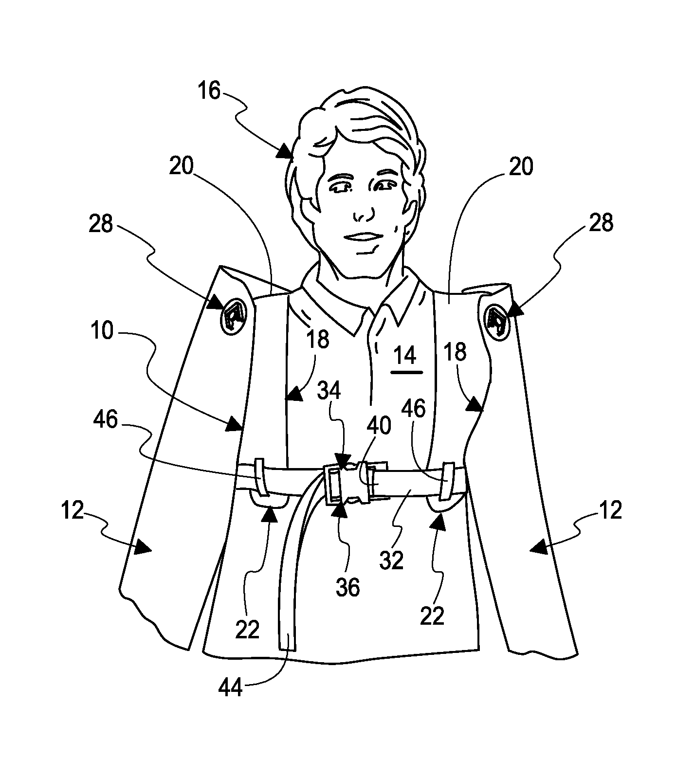
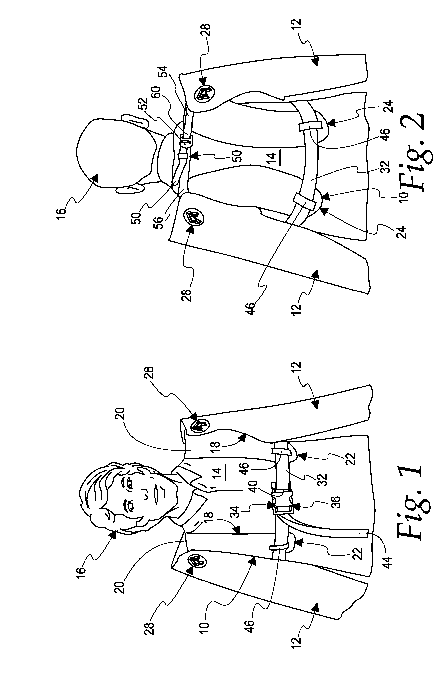
[0034] FIG. 1 is a perspective view from the front of a harness according to this disclosure as worn by a user with a pair of insulating sleeves;
[0035] FIG. 2 is a perspective view from behind of the harness and insulating sleeves of FIG. 1;
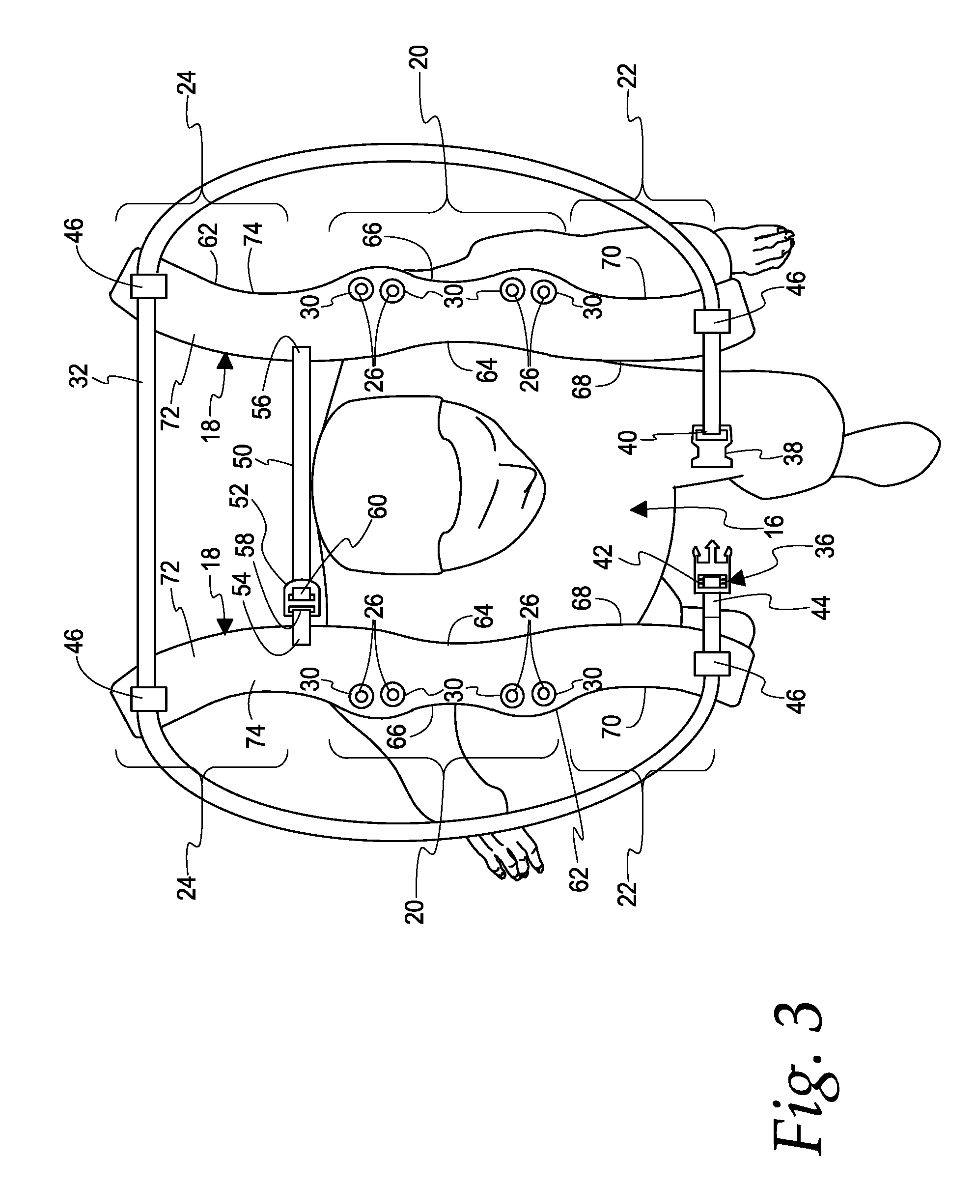
[0036] FIG. 3 is a somewhat diagrammatic plan view showing the harness of FIGS. 1 and 2 before it is fully placed upon a user;
[0037] FIG. 4 is a plan view showing the body contouring of a shoulder strap of the harness of FIGS. 1-3;
[0038] FIG. 5 is a view illustrating the layers of materials used for the shoulder strap shown in FIG. 4;
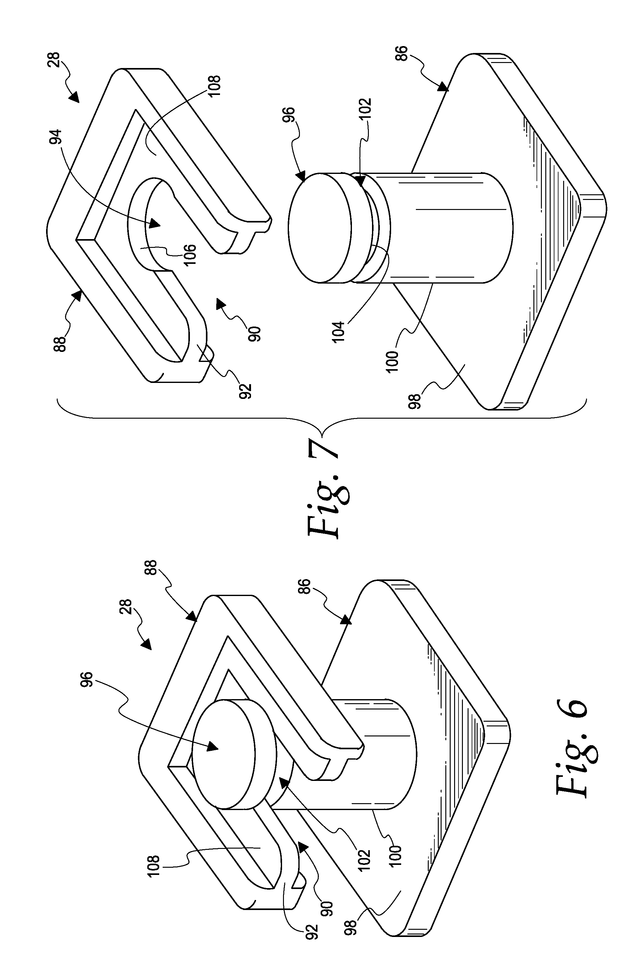
[0039] FIG. 6 is an isometric view from above of a fastener/button for connecting an insulating sleeve to the harness according to this disclosure;
[0040] FIG. 7 is a view similar to FIG. 6, but is an exploded view;
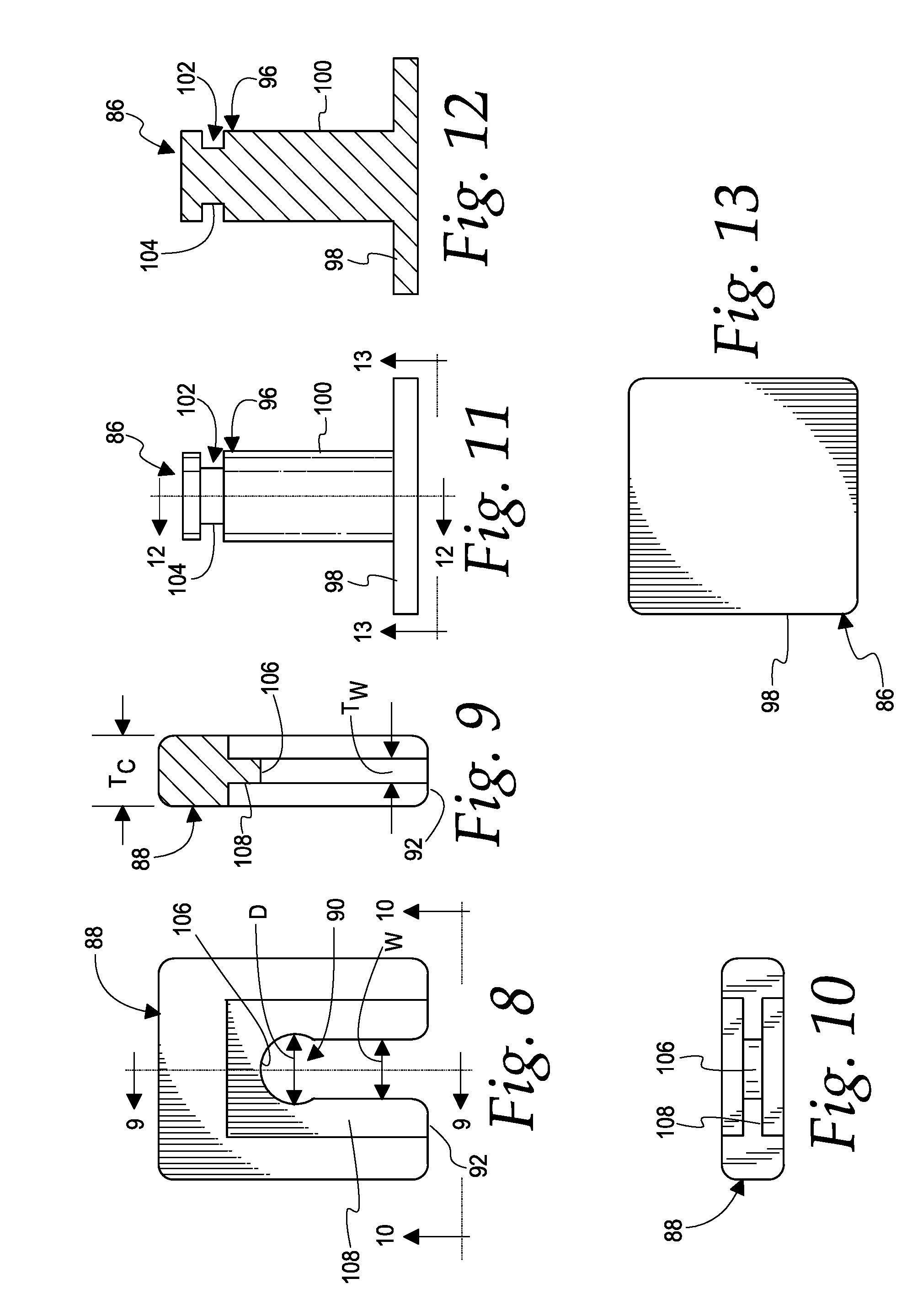
[0041] FIG. 8 is a plan view of the clip component of FIGS. 6 and 7;
[0042] FIG. 9 is a section view taken from line 9-9 in FIG. 8;
[0043] FIG. 10 is a view taken from line 10-10 in FIG. 8;
[0044] FIG. 11 is a view of an base/component of FIGS. 6 and 7;
[0045] FIG. 12 is a section view taken along line 12-12 in FIG. 11; and
[0046] FIG. 13 is a view taken from line 13-13 in FIG. 11.
DETAILED DESCRIPTION
[0047] With reference to FIGS. 1 and 2, a harness 10 is provided to secure a pair of electrical insulating sleeves 12 to the torso 14 of a user 16. The harness 10 includes a pair of sleeve support members in the form of shoulder straps 18 that are configured to extend downward over the top of the shoulders of a user 16 to the front and back of the torso 14 of the user 16 and to connect the sleeves 12 to the remainder of the harness 10. As best seen in FIG. 3, each of the shoulder straps 18 includes a middle portion 20 extending between opposite end portions 22 and 24. Each of the middle portions 20 include an array of fastener receiving openings 26, with the openings 26 being spaced along each of the members 18 so as to provide multiple mount locations for the corresponding sleeve 12. In this regard, in the illustrated embodiment, four fastener openings 26 are arranged in each of the middle portions 20 and are located to provide two distinct, different mounting positions/locations for each sleeve 12 relative to the shoulder strap 18. As shown in FIGS. 1 and 2, four releasable fasteners 28 are provided, two per sleeve 12, to releasably attach the sleeves 12 to the shoulder straps 18, with each releasable fastener 28 extending through one of the openings 26 in the shoulder straps 18 and a corresponding opening provided in the corresponding sleeve 12. In the illustrated embodiment, the openings 26 are defined by grommets 30 that protect the remainder of the strap 18 from the releasable fasteners 28 that are received in the opening 26.
[0048] The harness 10 further includes an adjustable chest strap 32 that is mounted to the opposite end portions 22 and 24 of each of the members 18 so as to extend horizontally around the middle portion (lower chest) of a user's torso 14 and to be tightened so as to secure the harness 10 to the user's torso 14. In the illustrated embodiment, a releasable buckle 34 is provided on the adjustable chest strap 32 and includes an integrated strap adjuster 36 that allows adjustments to the length of the strap 32 so that it can be tightened around the chest of a user 16. In this regard, in the illustrated embodiment, the releasable buckle 34 is in the form of a side release buckle 34 having a first part 38 of the buckle 34 fixed to an end 40 of the chest strap 32 and the other part 42 of the buckle 34 attached via the strap adjuster 36 to another end 44 of the strap 32. In the illustrated embodiment, loops 46 are provided on each of the end portions 22 and 24 of the shoulder straps 18, with the chest strap 32 slidably extending through each of the loops 46 to attach the chest strap 32 to the shoulder straps 18. The ability of the chest strap 32 to slide through the loops 46 allows for better adjustment and customization of the fit of the harness 10 to the torso 14. While any suitable construction and material may be used, in the illustrated embodiment, the chest strap 32 is provided in the form of a length of nylon webbing.
[0049] The harness 10 further includes an upper, shoulder adjustment strap 50 that is fixed to each of the shoulder straps 18 at a location that will extend across the back of the lower neck and upper shoulders of a user 16. In the illustrated embodiment, a suitable strap adjuster 52 is provided to adjust the length of strap 50. In this regard, the shoulder adjustment strap 50 has an end 54 fixed to one of the shoulder straps 18, such as by stitching or bonding, and another end 56 fixed to the other shoulder strap 18, again by any suitable means such as stitching or bonding. The shoulder adjustment strap 50 has another end 58 fixed to a loop in the strap adjuster 52, and another end 60 that is slidably received in the strap adjuster 52 to make adjustments in the length of the strap 50 in order to adjust the position of the middle portions 20 relative to each and to a user's neck and shoulders. Thus, it can be seen, that in the illustrated embodiment, the shoulder adjustment strap 50 is formed from two separate lengths of strapping that are engaged with the strap adjuster 52. While any suitable construction or material can be used for the shoulder adjustment strap 50, in the illustrated embodiment, the shoulder strap 50 is provided in the form of lengths of nylon webbing.
[0050] It should be understood that the grommets 30, the releasable buckle 34, the integrated strap adjuster 36, and the strap adjuster 52 can be of any suitable form and construction, many of which are known, and accordingly no limitation to a particular construction is intended unless expressly recited in an appended claim. In the illustrated embodiments, each of the components 30, 34, 36 and 52 are molded from a suitable plastic/polymer material.
[0051] As best seen in FIGS. 3 and 4, each of the shoulder straps 18 has a contoured shape wherein the perimeter/edge 62 of the shoulder strap 18 is contoured so as to provide a more comfortable fit to the torso 14 of a user 16. In this regard, as best seen in FIG. 4, in the illustrated embodiment, the middle portion 20 of each strap 18 has a concave peripheral edge 64 that faces the other middle portion 20 of the other strap 18 and another concave peripheral edge 66 facing away from the other middle portion 20 of the other strap 18 when the harness is worn by a user 16. Furthermore, each end portion 22 has a convex peripheral edge 68 facing the end portion 22 of the other strap 18 and a concave peripheral edge 70 facing away from the end portion 22 of the other strap 18 when worn by a user. Similarly, the each end portion 24 has a convex peripheral edge 72 facing the end portion 24 of the other strap 18 and a concave peripheral edge 74 facing in an opposite direction. Additionally, each shoulder strap 18 includes a pair of convex peripheral edges 76 adjacent the fastener receiving openings 26.
[0052] As best seen in FIG. 5, to further increase comfort for the user, each shoulder strap 18 of the illustrated embodiment is constructed of three layers of fabric, with an outer layer 78 of a durable material, such as a polyester multi-filament fabric coated with polyurethane (PU); a middle layer 80 of a cushioning/support material, such as a polyethylene foam of a closed cell type; and an inner layer 82 of breathable/wicking material, such as a layer of polyester filament mesh fabric. In the illustrated embodiment, the layers 78-82 are locked in place with a thicker edge tape 83 and sewn together with lines of stitching, shown diagrammatically at 84 in FIG. 5.
[0053] As best seen in FIGS. 6-13 in the illustrated embodiment, each releasable fastener 28 includes a base member 86 and a U-shaped clip member 88. The clip member 88 includes a centrally located slot 90 that extends from an edge 92 of the clip member 88 to a centrally located relief 94 that is configured for snap fit engagement with an end portion 96 of the base member 86. The base member 86 includes a base portion 98 and a cylindrical post 100 that extends perpendicular to the base portion 98, with the end of the post 100 defining the end portion 96. In the illustrated embodiment, the end portion 96 includes an annular groove 102 having a cylindrical base surface 104 that is sized to slide through the slot 90 and into snap fit engagement in the relief 94. In the illustrated embodiment, the relief 94 has a semi-circular shape defined by a semi-cylindrical wall surface 106, with the relief having diameter D that is greater than a width W of the slot 90 and sized to closely conform to the cylindrical surface 104 of the end portion 96. The slot 90 and relief 94 are formed in a central wall portion 108 of the clip member 88 that is centered in the clip member 88 and that has a thickness T.sub.w that is less than a thickness T.sub.c of the remainder of the clip 88.
[0054] Once the harness 10 is assembled, the end user 16 can attach the insulating sleeves 12 to the harness 10 using the fasteners 28. The setup can then be worn and adjusted per end user preference. The end user 16 can use the setup while wearing gloves and sleeves for live work performed on electrical utility lines.
[0055] It should be understood that while the embodiment of the harness 10 shown and described herein has a particular configuration, this disclosure contemplates modifications and other forms for the harness 10. For example, while shoulder straps 18 having a contoured shape will be desirable in many applications, in some applications it may be advantageous for the shoulder straps 18 to not have a contoured outer perimeter 62 and/or to have a contoured outer perimeter 62 that is different from the specific contoured outer perimeter 62 illustrated in the drawings. As a further example, while the releasable buckle 34 will be desirable in many applications, in some applications it may be advantageous for the chest strap 32 to simply be provided with some means for length adjustment, without being provided with a releasable buckle. By way of further example, while specific forms of strap adjusters have been shown, and will be desirable in many applications, some applications may utilize other means for adjusting the lengths of the chest strap 32 and the shoulder adjustment strap 50. As yet another example, while the multi-layer construction of the illustrated shoulder straps 18 will be desirable in many applications, in some applications, a single layer construction for the straps 18 may be desirable, either in the form of a single layer of fabric or a single layer of any other suitable material. Similarly, in some applications, it may be desirable for the shoulder straps 18 to have more than the three illustrated layers 78-82, and/or for the layers 78-82 to be formed from different fabrics and materials than those specifically described. As yet a further example, while the illustrated fasteners 28 will be desirable in many applications, in some applications, other suitable types of fasteners may be desired for use with the harness 10. Furthermore, while the illustrated fasteners 28 are shown as having particular shapes and geometries, other shapes and geometries may be desirable in some applications, such as, for example, a non-cylindrical shape for any of the posts 100, the base surface 104 and the wall surface 106, and/or a non-rectangular shape for the base portion 98, and/or a central wall portion 108 that is not centered in the clip member 88 or that does not have a thickness that is less than the thickness of the remainder of the clip 88. Similarly, while in many applications it will be desirable for each of the openings 26 to be defined by a grommet 30, in some applications it may be desirable for the grommets to be eliminated and/or for other means to define the openings 26, such as by providing a stitched seam around the opening 26. As yet a further example, while attachment of the chest strap 32 to the shoulder straps 18 using the loops 46 will be advantageous in many applications, other suitable structure for attachment may be desirable depending upon the specific requirements of an application. Accordingly, it should be understood, that no limitation to a specific configuration or form is intended unless expressly recited in one of the appended claims.
* * * * *
D00000
D00001
D00002
D00003
D00004
D00005
XML
uspto.report is an independent third-party trademark research tool that is not affiliated, endorsed, or sponsored by the United States Patent and Trademark Office (USPTO) or any other governmental organization. The information provided by uspto.report is based on publicly available data at the time of writing and is intended for informational purposes only.
While we strive to provide accurate and up-to-date information, we do not guarantee the accuracy, completeness, reliability, or suitability of the information displayed on this site. The use of this site is at your own risk. Any reliance you place on such information is therefore strictly at your own risk.
All official trademark data, including owner information, should be verified by visiting the official USPTO website at www.uspto.gov. This site is not intended to replace professional legal advice and should not be used as a substitute for consulting with a legal professional who is knowledgeable about trademark law.