Metal Battery, And Management System And Control Method Thereof
WANG; Lei ; et al.
U.S. patent application number 16/235615 was filed with the patent office on 2019-05-09 for metal battery, and management system and control method thereof. The applicant listed for this patent is SZ DJI TECHNOLOGY CO., LTD.. Invention is credited to Lei WANG, Wentao WANG, Bogao XU, Dayang ZHENG.
| Application Number | 20190140325 16/235615 |
| Document ID | / |
| Family ID | 60459080 |
| Filed Date | 2019-05-09 |


| United States Patent Application | 20190140325 |
| Kind Code | A1 |
| WANG; Lei ; et al. | May 9, 2019 |
METAL BATTERY, AND MANAGEMENT SYSTEM AND CONTROL METHOD THEREOF
Abstract
A battery management system includes a detection circuit configured to detect an electrical parameter of a metal battery and a control circuit configured to determine a safety performance of a battery cell of the metal battery according to the electrical parameter.
| Inventors: | WANG; Lei; (Shenzhen, CN) ; XU; Bogao; (Shenzhen, CN) ; WANG; Wentao; (Shenzhen, CN) ; ZHENG; Dayang; (Shenzhen, CN) | ||||||||||
| Applicant: |
|
||||||||||
|---|---|---|---|---|---|---|---|---|---|---|---|
| Family ID: | 60459080 | ||||||||||
| Appl. No.: | 16/235615 | ||||||||||
| Filed: | December 28, 2018 |
Related U.S. Patent Documents
| Application Number | Filing Date | Patent Number | ||
|---|---|---|---|---|
| PCT/CN2016/088241 | Jul 1, 2016 | |||
| 16235615 | ||||
| Current U.S. Class: | 1/1 |
| Current CPC Class: | G01R 31/392 20190101; H01M 10/482 20130101; H01M 10/52 20130101; H01M 10/54 20130101; G01R 31/378 20190101; G01R 31/52 20200101; H01M 10/425 20130101; H01M 10/441 20130101; G01R 19/16542 20130101; G01R 31/50 20200101; H01M 2010/4271 20130101; Y02W 30/84 20150501; G01R 31/382 20190101; H01M 10/48 20130101; G01R 31/3647 20190101 |
| International Class: | H01M 10/48 20060101 H01M010/48; G01R 31/382 20060101 G01R031/382; G01R 19/165 20060101 G01R019/165; H01M 10/44 20060101 H01M010/44; H01M 10/42 20060101 H01M010/42 |
Claims
1. A battery management system comprising: a detection circuit configured to detect an electrical parameter of a metal battery; and a control circuit configured to determine a safety performance of a battery cell of the metal battery according to the electrical parameter.
2. The battery management system of claim 1, wherein: the detection circuit includes at least one of a current detection circuit, a voltage detection circuit, or a voltameter, and/or the electrical parameter include at least one of an energy of the metal battery, a capacity of the metal battery, a voltage of the metal battery, a current of the metal battery, an energy of the battery cell, a capacity of the battery cell, a voltage of the battery cell, or a current of the battery cell.
3. The battery management system of claim 1, wherein the control circuit includes at least one of a microprocessor or a circuit including one or more circuit boards.
4. The battery management system of claim 1, further comprising: a memory electrically connected to the detection circuit and the control circuit, and storing the electrical parameter of the metal battery; wherein the control circuit is further configured to: obtain values of the electrical parameter of the metal battery at different times from the memory; and determine the safety performance of the battery cell of the metal battery according to the values of the electrical parameter at the different times.
5. The battery management system of claim 4, wherein: the memory further stores a preset value; and the control circuit is further configured to: determine a change value of the electrical parameter of the metal battery according to the values of the electrical parameter at the different times; and determine the safety performance of the battery cell of the metal battery according to a comparison result between the change value and the preset value.
6. The battery management system of claim 5, wherein the change value is determined when the metal battery is in a charging state.
7. The battery management system of claim 6, wherein: the electrical parameter includes at least one of a charging capacity or a charging energy of at least one of the metal battery or the battery cell; and the control circuit is further configured to, while the metal battery is in a constant voltage charging state: determine at least one of an increase rate of the charging capacity or an increase rate of the charging energy according to at least one of a difference of values of the charging capacity at the different times or a difference of values of the charging energy at the different times; and in response to the at least one of the increase rate of the charging capacity or the increase rate of the charging energy being greater than the preset value, determine that dendrites are formed inside the battery cell of the metal battery and positive and negative electrodes of the battery cell are connected by the dendrites.
8. The battery management system of claim 6, wherein: the electrical parameter includes a charging current of at least one of the metal battery or the battery cell; and the control circuit is further configured to, while the metal battery is in a constant voltage charging state: determine an increase rate of the charging current according to a difference of values of the charging current at the different times; and in response to the increase rate of the charging current being greater than the preset value, determine that dendrites are formed inside the battery cell of the metal battery and positive and negative electrodes of the battery cell are connected by the dendrites.
9. The battery management system of claim 6, wherein: the electrical parameter includes a charging energy of at least one of the metal battery or the battery cell; and the control circuit is further configured to, while the metal battery is in a constant current charging state: determine an increase rate of the charging energy according to a difference of values of the charging energy at the different times; and in response to the increase rate of the charging energy being greater than the preset value, determine that dendrites are formed inside the battery cell of the metal battery and positive and negative electrodes of the battery cell are connected by the dendrites.
10. The battery management system of claim 6, wherein: the electrical parameter includes a charging voltage of at least one of the metal battery or the battery cell; and the control circuit is further configured to, while the metal battery is in a constant current charging state: determine a decrease rate of the charging voltage according to a difference of values of the charging voltage at the different times; and in response to the decrease rate of the charging voltage being greater than the preset value, determine that dendrites are formed inside the battery cell of the metal battery and positive and negative electrodes of the battery cell are connected by the dendrites.
11. The battery management system of claim 5, wherein the change value is determined when the metal battery in a discharging state.
12. The battery management system of claim 11, wherein: the electrical parameter includes at least one of a discharging capacity or a discharging energy of at least one of the metal battery or the battery cell; and the control circuit is further configured to, while the metal battery is in the discharging state: determine at least one of an increase rate of the discharging capacity or an increase rate of the discharging energy according to at least one a difference of values of the charging capacity at the different times or a difference of values of the charging energy at the different times; and in response to the at least one of the increase rate of the discharging capacity or the increase rate of the discharging energy being less than the preset value, determine that dendrites are formed inside the battery cell of the metal battery and positive and negative electrodes of the battery cell are connected by the dendrites.
13. The battery management system of claim 11, wherein: the electrical parameter includes a discharging current of at least one of the metal battery or the battery cell; and the control circuit is further configured to, while the metal battery is in the discharging state: determine a decrease rate of the discharging current according to a difference of values of the discharging current at the different times; and in response to the decrease rate of the discharging current being greater than the preset value, determine that dendrites are formed inside the battery cell of the metal battery and positive and negative electrodes of the battery cell are connected by the dendrites.
14. The battery management system of claim 5, wherein the change value is determined when the metal battery is in a resting state.
15. The battery management system of claim 14, wherein: the electrical parameter includes at least one of a resting voltage or a remaining capacity of at least one of the metal battery or the battery cell; and the control circuit is further configured to, while the metal battery is in the resting state: determine at least one of a decrease rate of the resting voltage or a decrease rate of the remaining capacity according to at least one of a difference of values of the resting voltage at the different times or a difference of values of the remaining capacity at the different times; and in response to the at least one of the decrease rate of the resting voltage or the decrease rate of the remaining capacity being greater than the preset value, determine that dendrites are formed inside the battery cell of the metal battery and positive and negative electrodes of the battery cell are connected by the dendrites.
16. The battery management system of claim 5, wherein: the electronic parameter includes at least one of a total charging capacity or a total charging energy in a complete charging process from zero charge to full charge; and the control circuit is further configured to, in response to at least one of a difference between two values of the total charging capacity or a difference between two values of the total charging energy being greater than the preset value, determine that dendrites are formed inside the battery cell of the metal battery and positive and negative electrodes of the battery cell are connected by the dendrites, the two values of the total charging capacity being measured during two adjacent charging processes, respectively, and the two values of the total charging energy being measured during two adjacent charging processes, respectively.
17. The battery management system of claim 5, wherein: the electronic parameter includes at least one of a total discharging capacity or a total discharging energy in a complete discharging process from full charge to zero charge; and the control circuit is further configured to, in response to at least one of a difference between two values of the total discharging capacity or a difference between two values of the total discharging energy being greater than the preset value, determine that dendrites are formed inside the battery cell of the metal battery and positive and negative electrodes of the battery cell are connected by the dendrites, the two values of the total discharging capacity being measured during two adjacent discharging processes, respectively, and the two values of the total discharging energy being measured during two adjacent discharging processes, respectively.
18. The battery management system of claim 1, wherein: wherein the battery cell is one of a plurality of battery cells of the metal battery that are connected to each other; the battery management system further comprising: a memory electrically connected to the detection circuit and the control circuit respectively, and storing electrical parameters of the plurality of battery cells of the metal battery; wherein the control circuit is configured to: obtain values of the electrical parameters of the plurality of battery cells of the metal battery at a same time from the memory; and determine safety performance of the plurality of battery cells of the metal battery according to the electrical parameters at the same time.
19. The battery management system of claim 18, wherein: the memory further stores a preset value; the electronic parameters include resting voltages of the plurality of battery cells; and the control circuit is further configured to: determine resting voltage differences each being between two of the plurality of battery cells according to the resting voltages of the plurality of battery cells of the metal battery at the same moment in the resting state; determine a maximum value of the resting voltage differences; and determine the safety performance of the plurality of battery cells of the metal battery according to a comparison result between the maximum value of the resting voltage differences and the preset value.
20. The battery management system of claim 19, wherein the control circuit is further configured to, in response to the maximum value of the resting voltage differences being greater than the preset value, determine that dendrites are formed inside at least one of the plurality of battery cells of the metal battery and positive and negative electrodes of the at least one of the plurality of battery cells are connected by the dendrites.
Description
CROSS-REFERENCE TO RELATED APPLICATION
[0001] This application is a continuation application of International Application No. PCT/CN2016/088241, filed on Jul. 1, 2016, the entire contents of which are incorporated herein by reference.
TECHNICAL FIELD
[0002] The present disclosure relates to metal battery technology and, more particularly, to a metal battery, a management system and control method thereof.
BACKGROUND
[0003] Lithium metal batteries were born earlier than lithium-ion batteries, and Moli corporation commercialized and sold more than 2 million lithium metal batteries in the 1980s. Due to the safety hazards of lithium metal batteries, several serious safety incidents had been caused and Moli was forced to recall a large number of batteries. Later the company went bankrupt and was acquired. One of the important safety hazards is the lithium dendrite growth at the negative electrode that causes the internal short circuit of the battery and the associated thermal failure risk. The birth of lithium-ion batteries is largely to solve the safety problems of lithium-metal batteries. By adding the layered material of deintercalated lithium-ion, such as graphite, to the negative electrode, non-uniform growth of lithium metal during charging that causes the formation of dendrites and other problems is solved. However, adding the layered material of deintercalated lithium-ion to the negative electrode cause a decrease of the volume ratio, the weight ratio, and the energy density of the battery cells. With the expansion of battery application fields, the demand for high-energy-density batteries has become increasingly strong. However, lithium-ion batteries have reached the theoretical upper limit of the energy density, which cannot meet the growing demand, especially in application fields, such as electric vehicles, unmanned aerial vehicles (UVs), and mobile phones. Therefore, metal batteries, such as lithium metal batteries, magnesium metal batteries, sodium metal batteries, or the like, have again caused widespread interest and product attempts.
[0004] In conventional technologies, in order to suppress or solve the dendrite growth, a solid porous membrane that cannot be easily pierced is used or a third electrode between the positive and negative electrodes is introduced to monitor the dendrite growth. However, the conventional methods for solving the dendrite growth problem increase the difficulty of manufacturing the battery or the cost of the material in varying degree and reduce the performance of the battery. For example, although the use of the solid porous membrane prevents dendrite piercing to a certain extent, the ionic conductivity of the solid membrane is generally lower than the ionic conductivity of liquid or colloidal electrolyte, and good interfaces are difficult to be formed between the solid membrane and the positive and negative electrodes, thus, the discharging capacity of the battery cells becomes weak and the cycle life is reduced. By introducing the third electrode between the positive and negative electrodes, the formation of lithium dendrites is monitored and a certain degree of intervention is chosen to perform, but the complexity of the internal structure of the battery is increased, and the existing production equipment and processes cannot be consistent with the complex internal structure. The introduction of the new electrode brings other potential failure risks, reduces the reliability of the battery cells, and inevitably leads to a decline in production yield. Moreover, in order to be consistent with the function of the third electrode, the battery management system also becomes complicated accordingly.
SUMMARY
[0005] In accordance with the disclosure, there is provided a battery management system includes a detection circuit configured to detect an electrical parameter of a metal battery and a control circuit configured to determine a safety performance of a battery cell of the metal battery according to the electrical parameter.
BRIEF DESCRIPTION OF THE DRAWINGS
[0006] FIG. 1 schematically shows a formation process of a lithium dendrite inside a battery cell of a metal battery.
[0007] FIG. 2 schematically shows a short circuit between positive and negative electrodes of the battery cell of the metal battery induced by the formation of the lithium dendrite in FIG. 1.
[0008] FIG. 3 is a schematic diagram of an application environment of a battery management system provided inside a housing of a metal battery according to the disclosure.
[0009] FIG. 4 is a schematic diagram of another application environment of a battery management system provided separately from a metal battery according to the disclosure.
[0010] FIG. 5 schematically shows a battery cell of a metal battery in a charging state according to the disclosure.
[0011] FIG. 6 schematically shows a battery cell of a metal battery in a discharging state according to the disclosure.
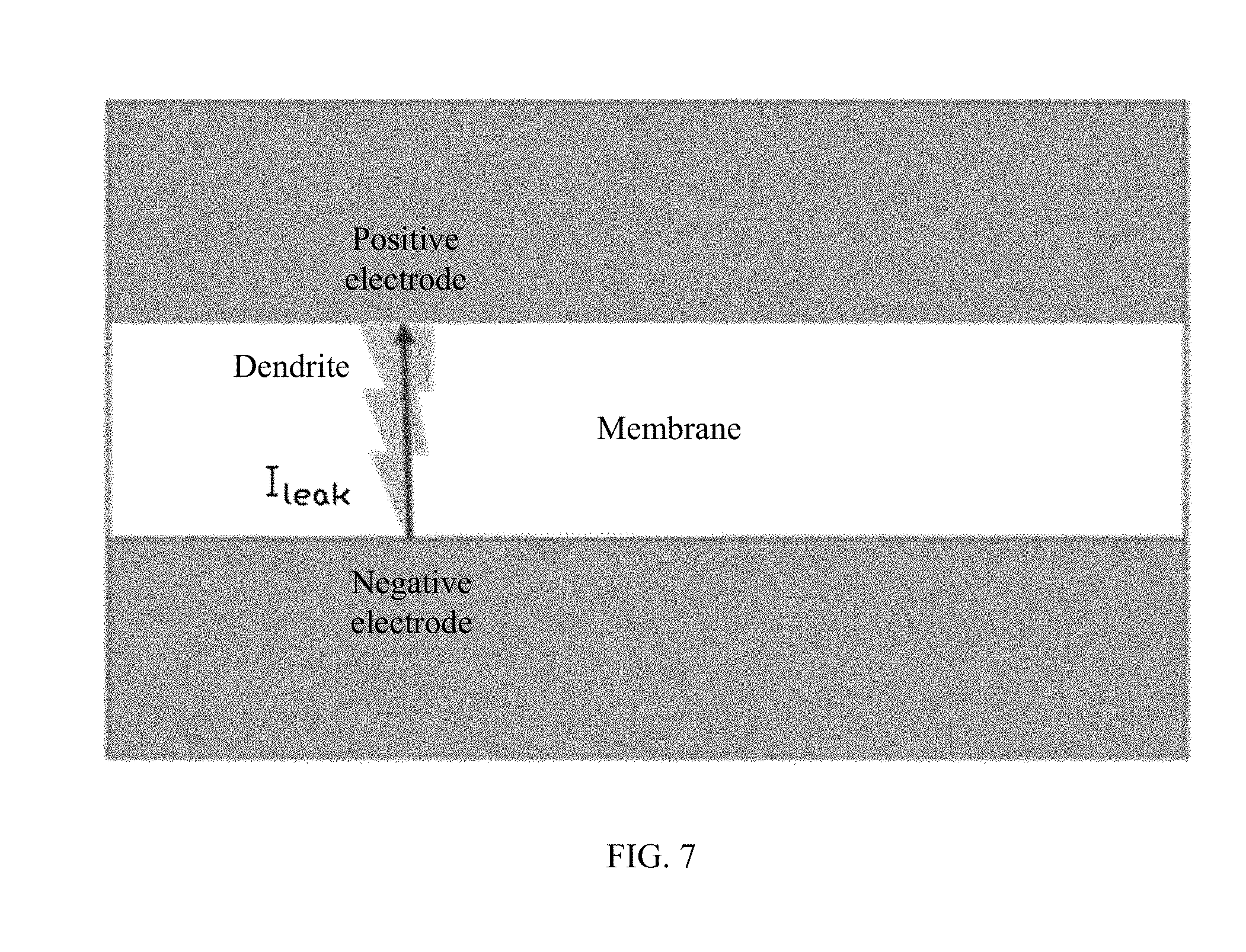
[0012] FIG. 7 schematically shows a battery cell of a metal battery in a resting state according to the disclosure.
[0013] FIG. 8 schematically shows a plurality of battery cells of a metal battery in a resting state according to the disclosure.
[0014] FIG. 9 is a schematic flow chart of a control method of a metal battery according to the disclosure.
[0015] FIG. 10 is a schematic view of a metal battery according to the disclosure.
[0016] FIG. 11 is a cross-sectional view of the metal battery in FIG. 10 along a XI-XI line.
[0017] Description of main components and Labels
TABLE-US-00001 battery management system (BMS) 100 detection circuit 11 control circuit 12 memory 13 indication unit 14 metal battery 200, 200' battery cell 21 cover 22 housing 23
DETAILED DESCRIPTION OF THE EMBODIMENTS
[0018] Exemplary embodiments will be described with reference to the accompanying drawings.
[0019] As used herein, when a first component is referred to as "fixed to" a second component, it is intended that the first component may be directly attached to the second component or may be indirectly attached to the second component via another component. When a first component is referred to as "connecting" to a second component, it is intended that the first component may be directly connected to the second component or may be indirectly connected to the second component via a third component between them. The terms "perpendicular," "horizontal," "left," "right," and similar expressions used herein are merely intended for description.
[0020] Unless otherwise defined, all the technical and scientific terms used herein have the same or similar meanings as generally understood by one of ordinary skill in the art. As described herein, the terms used in the specification of the present disclosure are intended to describe exemplary embodiments, instead of limiting the present disclosure. The term "and/or" used herein includes any suitable combination of one or more related items listed.
[0021] Technical solutions of the present disclosure will be described with reference to the drawings. It will be appreciated that the described embodiments are part rather than all of the embodiments of the present disclosure. Other embodiments conceived by those having ordinary skills in the art on the basis of the described embodiments without inventive efforts should fall within the scope of the present disclosure. In the situation where the technical solutions described in the embodiments are not conflicting, they can be combined.
[0022] The lithium dendrite growth inside a metal battery generally occurs during battery charging. FIG. 1 schematically shows an exemplary formation process of a lithium dendrite inside a battery cell of the metal battery. As shown in FIG. 1, taking a lithium metal battery as an example, due to uneven precipitation and growth of lithium metal on a negative electrode, lithium metal is deposited during a battery charging process, and a very thin solid electrolyte interface (SEI) film is quickly formed on the generated lithium metal surface. During the formation of lithium metal, the volume can swell that can cause damage to the SEI film. A dendritic dendrite can be formed over many cycles. A plurality of dendrites can be generated at different locations on the negative electrode surface inside the battery cell at the same time or at different times. FIG. 2 schematically shows a short circuit between the positive and negative electrodes of the battery cell of the metal battery induced by the formation of the lithium dendrite in FIG. 1. As shown in FIG. 2, as the dendrite grows, the dendrite finally pierces the membrane and reaches the positive electrode. As such, a local short circuit is formed inside the battery, which can cause a heat generation and even thermal runaway inside the battery that can induce irreversible serious failures, such as fire or even explosion.
[0023] FIG. 3 is a schematic diagram of an exemplary application environment of a battery management system (BMS) 100 provided inside a housing of a metal battery 200 consistent with the disclosure. The BMS 100 is configured to manage one or more battery cells 21 of the metal battery 200 and to monitor a safety performance of the one or more battery cells 21 of the metal battery 200.
[0024] As shown in FIG. 3, the BMS 100 includes at least a detection circuit 11 and a control circuit 12. The detection circuit 11 can be configured to detect electrical parameters of the metal battery 200.
[0025] In some embodiments, as shown in FIG. 3, the BMS 100 is provided inside the housing of the metal battery 200, and the detection circuit 11 can be electrically connected to the one or more battery cells of the metal battery 200.
[0026] FIG. 4 is a schematic diagram of another exemplary application environment of the BMS 100 provided separately from a metal battery 200 consistent with the disclosure. In some embodiments, as shown in FIG. 4, the BMS 100 is independent of the metal battery 200', and the detection circuit 11 can be electrically connected with the metal battery 200'.
[0027] The control circuit 12 can be configured to obtain the electrical parameters and determine the safety performance of the one or more battery cells 21 of the metal battery 200 according to the electrical parameters.
[0028] The control circuit 12 can include at least one of a microprocessor or a circuit comprising one or more circuit boards.
[0029] The detection circuit 11 can include at least one of a current detection circuit, a voltage detection circuit, or a voltameter (also called coulometer). The electrical parameters can include at least one of an energy of the metal battery, a capacity of the metal battery, a voltage of the metal battery, a current of the metal battery, energies of the one or more battery cells, capacities of the one or more battery cells, voltages of the one or more battery cells, or currents of the one or more battery cells.
[0030] The voltages can be directly detected by the voltage detection circuit. The currents can be directly detected by the current detection circuit. The capacities can be directly detected by the voltameter, or the currents can be firstly detected by the current detection circuit and the capacities can be calculated by integrating the currents over time. For the energies, the voltages can be detected by the voltage detection circuit, the currents can be detected by the current detection circuit, and the energies can be calculated by integrating products of the voltages and the currents over time.
[0031] For example, the detection circuit 11 can include the current detection circuit. The current detection circuit can be electrically connected to a charging circuit and/or a discharging circuit of the metal battery 200 and can be configured to detect charging currents in the charging circuit when the metal battery 200 is in a charging process and/or detect discharging currents in the discharging circuit when the metal battery 200 is in a discharging process.
[0032] In some embodiments, the control circuit 12 can calculate charging capacities during the charging process by integrating the charging currents over time, and/or calculate the discharging capacities during the discharging process by integrating the discharging currents over time.
[0033] In some embodiments, the detection circuit 11 can include the voltage detection circuit. The voltage detection circuit can be electrically connected between the positive and negative electrodes of the metal battery 200 or the one or more battery cells 21, and can be configured to detect charging voltages between the positive and negative electrodes of the metal battery 200 or the one or more battery cells during the charging process, detect discharging voltages between the positive and negative electrodes of the metal battery 200 or the one or more battery cells 21 during the discharging process, or detect resting voltages between the positive and negative electrodes of the metal battery 200 or the one or more battery cells 21 when the metal battery 200 is in a resting state.
[0034] In some embodiments, the detection circuit 11 can include the current detection circuit and the voltage detection circuit. The control circuit 12 can be configured to calculate charging energies by integrating the products of the charging currents and the charging voltages over time, and/or calculate discharging energies by integrating the products of the discharging currents and the discharging voltages over time.
[0035] In some embodiments, the detection circuit 11 can include the voltameter. The voltameter can be electrically connected to the charging circuit or the discharge circuit of the metal battery 200 and can be configured to detect the charging capacity of the metal battery 200 during the charging process or detect the discharging capacity of the metal battery 200 during the discharging process.
[0036] In some other embodiments, the voltameter can be electrically connected to the metal battery 200 or the one or more battery cells 21 and can be configured to detect the remaining capacity of the metal battery 200 when the metal battery 200 is in the resting state.
[0037] In some embodiments, the BMS 100 further includes a memory 13, and the memory 13 is electrically connected to the detection circuit 11 and the control circuit 12, respectively. The memory 13 can be configured to store the electrical parameters of the metal battery 200.
[0038] The control circuit 12 can be configured to obtain the electrical parameters of the metal battery 200 at different times from the memory 13 and determine the safety performance of the one or more battery cells 21 of the metal battery 200 according to the electrical parameters at the different times.
[0039] In some embodiments, the memory 13 can be also configured to store at least one preset value. The control circuit 12 can be configured to determine at least one change value of the electrical parameters of the metal battery 200 according to the electrical parameters at different times and determine the safety performance of the one or more battery cells 21 of the metal battery 200, according to at least one comparison result between the at least one change value and the at least one preset value.
[0040] The at least one change value can include a change rate, a change trend, or the like. The at least one preset value can be set as a maximum limit value or a minimum limit value of a normal variation range of the change rate, or a maximum limit value or a minimum limit value of a normal variation range of the change trend.
[0041] Taking the metal battery 200 having one battery cell 21 as an example, FIG. 5 schematically shows the battery cell 21 of the metal battery 200 in a charging state. Because when the metal battery 200 is in the charging process, the dendrites can be formed inside the battery cell 21 and the positive and negative electrodes of the battery cell 21 can be connected by the dendrites to cause a short circuit, a large amount of the charging capacity or the charging energy can be consumed, such that relatively sharp transitions of the electrical parameters of the metal battery 200 and/or the battery cell 21 can be generated. For example, a large rising transition of the charging capacity or the charging energy of the metal battery 200 and/or the large rising transition of the charging capacity or the charging energy of the battery cell 21 can be generated, or a large rising transition or a falling transition of the charging voltage or the charging current of the metal battery 200 and/or the large rising transition or the falling transition of the charging voltage or the charging current of the battery cell 21 can be generated. The BMS 100 can monitor the formation of dendrites during the charging of the metal battery 200 according to the above-described situations.
[0042] In some embodiments, the control circuit 12 can determine at least one change rate of the electrical parameters of the metal battery 200 in the charging state according to at least one of the electrical parameters of the metal battery 200 at different times and determine the safety performance of the battery cell 21 of the metal battery 200 according to at least one comparison result between the at least one change rate and the at least one preset value.
[0043] When the metal battery 200 is in the charging process, the charging capacity of the metal battery 200 can be calculated by integrating the charging current over time. The formula for calculating the charging capacity of the metal battery 200 can be expressed as:
Q.sub.charge=.intg. I.sub.chargedt
where Q.sub.charge denotes the charging capacity and the unit of Q.sub.charge can be mAh or Ah, and I.sub.charge denotes the charging current and the unit of I.sub.charge can be mA or A.
[0044] The charging energy of the metal battery 200 can be calculated by integrating the product of the charging voltage and the charging current over time during the charging process. The formula for calculating the charging energy of the metal battery 200 can be expressed as:
W.sub.charge=.intg. U.sub.chargeI.sub.chargedt
where W.sub.charge denotes the charging energy and the unit of W.sub.charge can be Wh or mWh, and U.sub.charge denotes the charging voltage and the unit of U.sub.charge can be mV or V.
[0045] Inside the metal battery 200, the current actually used by the battery cell 21 of the metal battery 200 to generate electricity is I.sub.cell, and the actual charging capacity of the metal battery 200 is Q.sub.0. The calculation formula of the charging capacity Q.sub.0 actually generated by the battery cell 21 of the metal battery 200 can be expressed as:
Q.sub.0=.intg. I.sub.celldt
[0046] If dendrites are formed inside the battery cell 21 of the metal battery 200, a dendrite leakage-current is I.sub.leak, the charging current I.sub.charge=I.sub.leak+I.sub.cell, and the charging voltage U.sub.charge=U.sub.cell=I.sub.cellR.sub.cell, where R.sub.cell is a resistance of the batter cell 21.
[0047] A calculation formula for a capacity Q.sub.leak consumed by the dendrites can be expressed as:
Q.sub.leak=.intg. I.sub.leakdt
and Q.sub.charge=Q.sub.leak+Q.sub.0.
[0048] An energy W.sub.leak consumed by the dendrites can be expressed as:
W.sub.leak=.intg. U.sub.leakI.sub.leakdt
where W.sub.charge=W.sub.leak+W.sub.0, W.sub.0 is an actual charging energy of the metal battery 200.
[0049] The charging currents at different times T1 and T2 are set as I.sub.T2 and I.sub.T1, respectively, where T2>T1 (T2 is a later time point than T1) and a time interval .DELTA.t=T2-T1, thus a change rate v.sub.i of the charging current I.sub.charge can be expressed as:
v.sub.i=.DELTA.I.sub.charge/.DELTA.t=|I.sub.T2-I.sub.T1|/.DELTA.t
when I.sub.T2>I.sub.T1, the change rate v.sub.i can be an increase rate of the charging current I.sub.charge, and when I.sub.T2<I.sub.T1, the change rate v.sub.i can be a decrease rate of the charging current I.sub.charge.
[0050] The charging voltages at different times T1 and T2 are set as U.sub.T2 and U.sub.T1, respectively, and a change rate v.sub.u of the charging voltage U.sub.charge can be expressed as:
v.sub.u=.DELTA.U.sub.charge/.DELTA.t=|U.sub.T2-U.sub.T1|/.DELTA.t
when U.sub.T2>U.sub.T1, the change rate v.sub.u can be an increase rate of the charging voltage U.sub.charge, and when U.sub.T2<U.sub.T1, the change rate v.sub.u can be a decrease rate of the charging voltage U.sub.charge.
[0051] The charging capacity at different times T1 and T2 are set as Q.sub.T2 and Q.sub.T1, respectively, and a change rate v.sub.q of the charging capacity Q.sub.charge can be expressed as:
v.sub.q=.DELTA.Q.sub.charge/.DELTA.t=|Q.sub.T2-Q.sub.T1|/.DELTA.t
when Q.sub.T2>Q.sub.T1, the change rate v.sub.q can be an increase rate of the charging capacity Q.sub.charge, and when Q.sub.T2<Q.sub.T1, the change rate v.sub.q can be a decrease rate of the charging capacity Q.sub.charge.
[0052] The charging energy at different times T1 and T2 are set as W.sub.T2 and W.sub.T1, respectively, and a change rate v.sub.w of the charging energy W.sub.charge can be expressed as:
v.sub.w=.DELTA.W.sub.charge/.DELTA.t=|W.sub.T2-W.sub.T1|/.DELTA.t
when W.sub.T2>W.sub.T1, the change rate v.sub.w can be an increase rate of the charging energy W.sub.charge, and when W.sub.T2<W.sub.T1, the change rate v.sub.w can be a decrease rate of the charging energy W.sub.charege.
[0053] In some embodiments, the electrical parameters can include the charging current of the metal battery 200 and/or the charging current of the battery cell 21.
[0054] The control circuit 12 can determine the increase rate of the charging current, according to a difference of the charging currents at different times, when the metal battery 200 is in a constant voltage charging state. When the increase rate of the charging current is greater than the preset value, it can be determined that the dendrites are formed inside the battery cell 21 of the metal battery 200 and the positive and negative electrodes of the battery cell 21 are connected by the dendrites.
[0055] In the constant voltage charging process, because the charging voltage U.sub.charge remains substantially unchanged, the current of the battery cell I.sub.cell also remains unchanged.
[0056] If the positive and negative electrodes of the battery cell 21 are connected by the dendrites to cause the internal short circuit in the battery cell 21, the dendrite leakage-current I.sub.leak can become a short-circuit current and becomes a very large value.
[0057] A preset value P.sub.I1 can be set as the maximum limit value of the change rate of the charging current I.sub.charege within the normal variation range. According to the above description, the increase of the dendrite leakage-current I.sub.leak can cause the rising transition of the charging current I.sub.charge, such that the increase rate v.sub.i of the charging current I.sub.charge can be greater than the preset value P.sub.I1. Therefore, it can be determined that the dendrites are formed inside the battery cell 21 of the metal battery 200 and the positive and negative electrodes of the battery cell 21 are connected by the dendrites.
[0058] In some embodiments, the electrical parameters can include the charging capacity and/or the charging energy of the metal battery 200 and/or the charging capacity and/or the charging energy of the battery cell 21.
[0059] The control circuit 12 can determine the increase rate of the charging capacity and/or the increase rate of the charging energy, according to a difference of the charging capacities and/or a difference of the charging energies at different times, when the metal battery 200 is in the constant voltage charging state. When the increase rate of the charging capacity and/or the increase rate of the charging energy are greater than the corresponding preset values, it can be determined that the dendrites are formed inside the battery cell 21 of the metal battery 200 and the positive and negative electrodes of the battery cell 21 are connected by the dendrites.
[0060] A preset value P.sub.Q1 can be set as the maximum limit value of the change rate of the charging capacity Q.sub.charge within the normal variation range. According to the above description, the increase of the dendrite leakage-current Leak can cause an increase of the capacity Q.sub.leak costed by the dendrites and the rising transition of the charging current I.sub.charge, such that a rising transition of the charging capacity Q.sub.charge can be generated. Therefore, the increase rate v.sub.q of the charging capacity Q.sub.charge can be greater than the preset value P.sub.Q1, and it can be determined that the dendrites are formed inside the battery cell 21 of the metal battery 200 and the positive and negative electrodes of the battery cell 21 are connected by the dendrites.
[0061] A preset value P.sub.W1 can be set as the maximum limit value of the change rate of the charging energy W.sub.charge within the normal variation range. According to the above description, the increase of the dendrite leakage-current Leak can cause an increase of an energy W.sub.leak costed by the dendrites, such that a rising transition of the charging energy W.sub.charge can be generated. Therefore, the increase rate vw of the charging energy W.sub.charge can be greater than the preset value P.sub.W1, and it can be determined that the dendrites are formed inside the battery cell 21 of the metal battery 200 and the positive and negative electrodes of the battery cell 21 are connected by the dendrites.
[0062] In some embodiments, the electrical parameters can include the charging voltage of the metal battery 200 and/or the charging voltage of the battery cell 21.
[0063] The control circuit 12 can determine the decrease rate of the charging voltage, according to a difference of the charging voltages at different times, when the metal battery 200 is in a constant current charging state. When the decrease rate of the charging voltage is greater than the preset value, it can be determined that the dendrites are formed inside the battery cell 21 of the metal battery 200 and the positive and negative electrodes of the battery cell 21 are connected by the dendrites.
[0064] In the constant current charging process, because the charging current I.sub.charge remains substantially unchanged, the voltage of the battery cell U.sub.cell can gradually decrease in normal situations.
[0065] A preset value P.sub.U1 can be set as the maximum limit value of the change rate of the charging voltage U.sub.charge within the normal variation range. According to the above description, the increase of the dendrite leakage-current I.sub.leak can cause a falling transition of the current of the battery cell I.sub.cell and a falling transition of the charging voltage U.sub.charge, such that the decrease rate v.sub.u of the charging voltage U.sub.charge can be greater than the preset value P.sub.U1. Therefore, it can be determined that the dendrites are formed inside the battery cell 21 of the metal battery 200 and the positive and negative electrodes of the battery cell 21 are connected by the dendrites.
[0066] In some embodiments, the electrical parameters can include the charging energy of the metal battery 200 and/or the charging energy of the battery cell 21.
[0067] The control circuit 12 can determine the increase rate of the charging energy, according to the difference of the charging energies at different times, when the metal battery 200 is in a constant current charging state. When the increase rate of the charging energy is less than the preset value, it can be determined that the dendrites are formed inside the battery cell 21 of the metal battery 200 and the positive and negative electrodes of the battery cell 21 are connected by the dendrites.
[0068] A preset value P.sub.W2 can be set as the minimum limit value of the change rate of the charging energy W.sub.charge within the normal variation range. According to the above description, the charging current I.sub.charge remains substantially unchanged in the constant current charging process, and the increase of the dendrite leakage-current I.sub.leak can cause the falling transition of the charging voltage U.sub.charge, such that the increase rate of the charging energy W.sub.charge can be slowed down, causing the decrease rate v.sub.w2 of the charging energy W.sub.charge to be less than the preset value P.sub.W2. Hence, it can be determined that the dendrites are formed inside the battery cell 21 of the metal battery 200 and the positive and negative electrodes of the battery cell 21 are connected by the dendrites.
[0069] In the constant current charging process, because the charging current I.sub.charge remains substantially unchanged, the charging capacity Q.sub.charge can increase as a normal speed. That is, the change rate of the charging capacity Q.sub.charge can be within the normal variation range.
[0070] FIG. 6 schematically shows the battery cell 21 of the metal battery 200 in a discharging state consistent with the disclosure. Because when the metal battery 200 is in the discharging process, the dendrites can also be formed inside the battery cell 21 and the positive and negative electrodes of the battery cell 21 can be connected by the dendrites to cause the short circuit, a large amount of the discharging capacity or the discharging energy can be consumed, such that the relatively sharp transitions of the electrical parameters of the metal battery 200 and/or the battery cell 21 can be generated. For example, a large falling transition of the discharging capacity or the discharging energy of the metal battery 200 and/or the large falling transition of the discharging capacity or the discharging energy of the battery cell 21 can be generated, or a large rising transition or a falling transition of the discharging voltage or the discharging current of the metal battery 200 and/or the large rising transition or the falling transition of the discharging voltage or the discharging current the battery cell 21 can be generated. The BMS 100 can monitor the formation of dendrites during the discharging of the metal battery 200 according to the above-described situations.
[0071] In some embodiments, the control circuit 12 can determine at least one change rate of the electrical parameters of the metal battery 200 in the discharging state, according to at least one of the electrical parameters of the metal battery 200 at different times, and determine the safety performance of the battery cell 21 of the metal battery 200, according to at least one comparison result between the at least one change rate and the at least one preset value.
[0072] When the metal battery 200 is in the discharging process, inside the metal battery 200, the current actually used by the battery cell 21 of the metal battery 200 to generate electricity is Len and the actual discharging capacity of the metal battery 200 is Q.sub.d0. The formula for calculating the actual discharging capacity Qdo of the metal battery 200 can be expressed as:
Q.sub.d0=.intg. I.sub.celldt
[0073] The discharging capacity of the metal battery 200 can be calculated by integrating the discharging current over time during the discharging process. The formula for calculating the discharging capacity of the metal battery 200 can be expressed as:
Q.sub.discharge=.intg. I.sub.dischargedt
where Q.sub.discharge denotes the discharging capacity and the unit of Q.sub.discharge can be mAh or Ah, and I.sub.discharge denoted the discharging current and the unit of I.sub.discharge can be mA or A.
[0074] The discharging energy of the metal battery 200 can be calculated by integrating the product of the discharging voltage and the discharging current over time during the discharging process. The formula for calculating the discharging energy of the metal battery 200 can be expressed as:
W.sub.discharge=.intg. U.sub.dischargeI.sub.dischargedt
where W.sub.discharge denotes the discharging energy and the unit of W.sub.discharge can be Wh or mWh, and U.sub.discharge denotes the discharging voltage and the unit of U.sub.discharge can be mV or V.
[0075] If dendrites are formed inside the battery cell 21 of the metal battery 200, the discharging current I.sub.discharge=I.sub.leak-I.sub.cell, and the discharging voltage U.sub.discharge=U.sub.cell=I.sub.cellR.sub.cell, the discharging capacity Q.sub.discharge=Q.sub.d0-Q.sub.leak, and the discharging energy W.sub.discharge=W.sub.d0-W.sub.leak.
[0076] The discharging currents at different times T1 and T2 are set as I.sub.dT2 and I.sub.dT1, respectively, where T2>T1 and the time interval .DELTA.t=T2-T1, thus, a change rate v.sub.di of the discharging current I.sub.discharge can be expressed as:
v.sub.di=.DELTA.I.sub.discharge/.DELTA.t=|I.sub.dT2-I.sub.dT1/.DELTA.t
when I.sub.dT2>I.sub.dT1, the change rate v.sub.di can be an increase rate of the discharging current I.sub.discharge, and when I.sub.dT2<I.sub.dT1, the change rate v.sub.di can be a decrease rate of the discharging current I.sub.discharge.
[0077] The discharging voltages at different times T1 and T2 are set as U.sub.dT2 and U.sub.dT1, respectively, thus, a change rate v.sub.du of the discharging voltage U.sub.discharge can be expressed as:
v.sub.du=.DELTA.U.sub.discharge/.DELTA.t=|U.sub.dT2-U.sub.dT1|/.DELTA.t
when U.sub.dT2>U.sub.dT1, the change rate vdu can be an increase rate of the discharging voltage U.sub.discharge, and when U.sub.dT2<U.sub.dT1, the change rate vdu can be a decrease rate of the discharging voltage U.sub.discharge.
[0078] The discharging capacities at different times T1 and T2 are set as Q.sub.dT2 and Q.sub.dT1, respectively, thus, a change rate v.sub.dq of the discharging capacity Q.sub.discharge can be expressed as:
v.sub.dq=.DELTA.Q.sub.discharge/.DELTA.t=|Q.sub.dT2-Q.sub.dT1|/.DELTA.t
when Q.sub.dT2>Q.sub.dT1, the change rate v.sub.dq can be an increase rate of the discharging capacity Q.sub.discharge, and when Q.sub.dT2<Q.sub.dT1, the change rate v.sub.dq can be a decrease rate of the discharging capacity Q.sub.discharge.
[0079] The discharging energies at different times T1 and T2 are set as W.sub.dT2 and W.sub.dT1, respectively, thus, a change rate v.sub.dw of the discharging energy W.sub.discharge can be expressed as:
v.sub.dw=.DELTA.W.sub.discharge/.DELTA.t=|W.sub.dT2-W.sub.dT1|/.DELTA.t
when W.sub.dT2>W.sub.dT1, the change rate yaw can be an increase rate of the discharging energy W.sub.discharge, and when W.sub.dT2<W.sub.dT1, the change rate yaw can be a decrease rate of the discharging energy W.sub.discharge.
[0080] In some embodiments, the electrical parameters can include the discharging current of the metal battery 200 and/or the discharging current of the battery cell 21.
[0081] The control circuit 12 can determine a decrease rate of the discharging current, according to a difference of the discharging currents at different times, when the metal battery 200 is in the discharging state. When the decrease rate of the discharging current is greater than the preset value, it can be determined that the dendrites are formed inside the battery cell 21 of the metal battery 200 and the positive and negative electrodes of the battery cell 21 are connected by the dendrites.
[0082] In the discharging process, inside the metal battery 200, the current I.sub.cell actually used by the battery cell 21 of the metal battery 200 to generate electricity can gradually decrease in normal situations.
[0083] A preset value P.sub.I2 can be set as the maximum limit value of the change rate of the discharging current I.sub.discharge within the normal variation range. According to the above description, the increase of the dendrite leakage-current I.sub.leak can cause a falling transition of the discharging current I.sub.discharge, such that the decrease rate v.sub.di of the discharging current I.sub.discharge can be greater than the preset value P.sub.I2. Therefore, it can be determined that the dendrites are formed inside the battery cell 21 of the metal battery 200 and the positive and negative electrodes of the battery cell 21 are connected by the dendrites.
[0084] In addition, as described above, in the discharging process, the current I.sub.cell actually used by the battery cell 21 of the metal battery 200 to generate electricity can gradually decrease in normal situations. According to the above description, the discharging voltage U.sub.discharge can also gradually decrease at a normal speed. That is, the change rate v.sub.du of the discharging voltage U.sub.discharge can be within the normal variation range.
[0085] In some embodiments, the electrical parameters can include the discharging capacity and/or the discharging energy of the metal battery 200 and/or the discharging capacity and/or the discharging energy of the battery cell 21.
[0086] The control circuit 12 can determine the increase rate of the discharging capacity and/or the increase rate of the discharging energy, according to a difference of the discharging capacities and/or a difference of the discharging energies at different times, when the metal battery 200 is in the discharging state. When the increase rate of the discharging capacity and/or the increase rate of the discharging energy are less than the corresponding preset values, it can be determined that the dendrites are formed inside the battery cell 21 of the metal battery 200 and the positive and negative electrodes of the battery cell 21 are connected by the dendrites.
[0087] A preset value P.sub.Q3 can be set as the minimum limit value of the change rate the discharging capacity Q.sub.discharge within the normal variation range. According to the above description, the increase of the dendrite leakage-current I.sub.leak can cause an increase of the capacity Q.sub.leak costed by the dendrites and the falling transition of the discharging current I.sub.discharge, such that the increase rate of the discharging capacity Q.sub.discharge can be slowed down, causing the increase rate v.sub.dq of the discharging capacity Q.sub.discharge to be less than the present value p.sub.Q3. Therefore, it can be determined that the dendrites are formed inside the battery cell 21 of the metal battery 200 and the positive and negative electrodes of the battery cell 21 are connected by the dendrites.
[0088] A preset value P.sub.W3 can be set as the minimum limit value of the change rate of the discharging energy W.sub.discharge within the normal variation range. According to the above description, the increase of the dendrite leakage-current I.sub.leak can cause the falling transition of the discharging current I.sub.discharge, a slow decrease of the discharging voltage U.sub.discharge at the normal speed, and an increase of the energy W.sub.leak costed by the dendrites, such that the increase rate v.sub.dw of the discharging energy W.sub.discharge can be less than the preset value P.sub.3. Therefore, it can be determined that the dendrites are formed inside the battery cell 21 of the metal battery 200 and the positive and negative electrodes of the battery cell 21 are connected by the dendrites.
[0089] FIG. 7 schematically shows the battery cell 21 of the metal battery 200 in a resting state consistent with the disclosure. Because when the metal battery 200 is in the resting state, i.e., a non-charging and non-discharging state, the dendrites can also be formed inside the battery cell 21 due to internal or external extrusions, hits, or the like, and the positive and negative electrodes of the battery cell 21 can be connected by the dendrites to cause the short circuit, a large amount of capacity can be consumed, such that the relatively sharp transitions of the electrical parameters of the metal battery 200 and/or the battery cell 21 can be generated. For example, a large falling transition of a remaining capacity of the metal battery 200 and/or the large falling transition of the remaining capacity of the battery cell 21 can be generated, or a large falling transition of a resting voltage of the metal battery 200 and/or the large falling transition of the resting voltage of the battery cell 21 can be generated. The BMS 100 can monitor the formation of dendrites in the metal battery 200 during the rest state according to the above-described situations.
[0090] In some embodiments, the control circuit 12 can determine at least one change rate of the electrical parameters of the metal battery 200 in the resting state, according to at least one of the electrical parameters of the metal battery 200 at different times, and determine the safety performance of the battery cell 21 of the metal battery 200 according to at least one comparison result between the at least one change rate and the at least one preset value.
[0091] When the metal battery 200 is in the resting state, in normal situations, the resting voltage U.sub.+- between the positive and negative electrodes of the battery cell 21 gradually decreases, the remaining capacity Q.sub.r in the resting state also gradually decreases, and Q.sub.r=Q.sub.t-Q.sub.leak, where Q.sub.t denotes a total capacity in the resting state.
[0092] The resting voltages at different times T1 and T2 are set as U.sub.rT2 and U.sub.rT1, respectively, thus, a change rate v.sub.ru of the resting voltage U.sub.+- can be expressed as:
V.sub.du=.DELTA.U.sub.+-/.DELTA.t=|U.sub.rT2-U.sub.rT1|/.DELTA.t
[0093] The remaining capacities at different times T1 and T2 are set as Q.sub.rT2 and Q.sub.rT1, respectively, thus, a change rate v.sub.rq of the remaining capacity Q.sub.r can be expressed as:
v.sub.rq=.DELTA.Q.sub.r/.DELTA.t=|Q.sub.rT2-Q.sub.rT1|/.DELTA.t
[0094] In some embodiments, the electrical parameters can include the resting voltage and/or the remaining capacity of the metal battery 200 and/or the resting voltage and/or the remaining capacity of the battery cell 21.
[0095] The control circuit 12 can determine the decrease rate of the resting voltage and/or the decrease rate of the remaining capacity, according to a difference of the resting voltages and/or a difference of the remaining capacities at different times, when the metal battery 200 is in the resting state. When the decrease rate of the resting voltage and/or the decrease rate of the remaining capacity is greater than the corresponding preset value, it can be determined that the dendrites are formed inside the battery cell 21 of the metal battery 200 and the positive and negative electrodes of the battery cell 21 are connected by the dendrites.
[0096] A preset value P.sub.U3 can be set as the maximum limit value of the change rate of the resting voltage U.sub.+- within the normal variation range. According to the above description, the short circuit induced by the positive and negative electrodes of the battery cell 21 connected by the dendrites can cause the falling transition of the resting voltage U.sub.+-, such that the decrease rate v.sub.rq of the resting voltage U.sub.+- can be greater than the preset value P.sub.U3. Therefore, it can be determined that the dendrites are formed inside the battery cell 21 of the metal battery 200 and the positive and negative electrodes of the battery cell 21 are connected by the dendrites.
[0097] A preset value P.sub.Q4 can be set as the maximum limit value of the change rate of the remaining capacity Q.sub.r within the normal variation range. According to the above description, the increase of the dendrite leakage-current I.sub.leak can cause the increase of the capacity Q.sub.leak costed by the dendrites, such that the falling transition of the remaining capacity Q.sub.r can be generated, causing the decrease rate v.sub.rq of the remaining capacity Q.sub.r to be greater than the preset value P.sub.Q4. Hence, it can be determined that the dendrites are formed inside the battery cell 21 of the metal battery 200 and the positive and negative electrodes of the battery cell 21 are connected by the dendrites.
[0098] FIG. 8 schematically shows a plurality of battery cells 21 of the metal battery 200 in the resting state consistent with the disclosure. The metal battery 200 can include the plurality of battery cells 21 connected in series and/or in parallel.
[0099] In some embodiments, the memory 13 can be configured to store the electrical parameters of the plurality of battery cells 21 of the metal battery 200. The control circuit 12 can be configured to obtain the electrical parameters of the plurality of battery cells 21 of the metal battery 200 at a same time from the memory 13 and determine the safety performance of the plurality of battery cells 21 of the metal battery 200 according to the electrical parameters at the same time.
[0100] In some embodiments, the electronic parameters can include the resting voltages of the plurality of battery cells 21. The control circuit 12 can be configured to determine resting voltage differences between each two of the plurality of battery cells 21, according to the resting voltages of the plurality of battery cells 21 of the metal battery 200 at the same moment in the resting state, and determine a maximum value of the resting voltage differences between each two of the plurality of battery cells 21. The safety performance of the plurality of battery cells 21 of the metal battery 200 can be determined according to a comparison result between the maximum value of the resting voltage differences between each two of the plurality of battery cells 21 and the preset value.
[0101] Furthermore, when the maximum value of the resting voltage differences between each two of the plurality of battery cells 21 is greater than the preset value, the control circuit can determine that the dendrites are formed inside at least one of the plurality of battery cells 21 of the metal battery 200 and the positive and negative electrodes of at least one of the plurality of battery cells 21 are connected by the dendrites.
[0102] In some embodiments, the maximum value of the resting voltage differences, also referred to as a maximum resting voltage difference, between each two of the plurality of battery cells 21 can be expressed as:
.DELTA.U=max{U.sub.i-U.sub.j}, i.noteq.j,1.ltoreq.i,j.ltoreq.n
where n denotes the number of the plurality of battery cells 21 of the metal battery 200.
[0103] In normal situations, the differences between the resting voltage differences between each two of the plurality of battery cells 21 are not too great.
[0104] A preset value P.sub.U4 can be set as the maximum limit value of the maximum value .DELTA.U of the resting voltage differences within the normal variation range. The short circuit induced by the positive and negative electrodes of at least one of the plurality of battery cells 21 connected by the dendrites can cause the falling transition of the resting voltage U.sub.+-, such that the maximum value .DELTA.U of the resting voltage differences can be greater than the preset value P.sub.U4. Therefore, it can be determined that the dendrites are formed inside at least one of the plurality of battery cells 21 of the metal battery 200 and the positive and negative electrodes of at least one of the plurality of battery cells 21 are connected by the dendrites.
[0105] The BMS 100 can timely and effectively discover the formation of the dendrites by using the methods described above, such that the safety measures can be performed in time and the safety accidents can be avoided.
[0106] In some embodiments, the electronic parameters can include a total charging capacity and/or a total charging energy in a complete charging process from zero charge to full charge.
[0107] When a difference between two adjacent total charging capacities and/or a difference between two adjacent total charging energies are greater than the corresponding preset values, the control circuit 12 can determine that the dendrites are formed inside the one or more battery cells 21 of the metal battery 200 and the positive and negative electrodes of the one or more battery cells 21 are connected by the dendrites.
[0108] In normal situations, the difference between two adjacent total charging capacities and/or the difference between two adjacent total charging energies are not too great in the complete charging process from zero charge to full charge.
[0109] The two adjacent total charging capacities are set as Q.sub.2 and Q.sub.1 respectively, thus the difference .DELTA.Q.sub.charge between two adjacent total charging capacities can be expressed as:
.DELTA.Q.sub.charge=|Q.sub.2-Q.sub.1|
[0110] The two adjacent total charging energies are set as W.sub.2 and W.sub.1 respectively, thus the difference .DELTA..sub.charge between two adjacent total charging energies can be expressed as:
.DELTA.W.sub.charge=|W.sub.2-W.sub.1|
[0111] A preset value P.sub.Q5 can be set as the maximum limit value of the difference of the two adjacent total charging capacities within the normal variation range. Because the total charging capacity Q.sub.charge=Q.sub.leak+Q.sub.0, when the positive and negative electrodes of the one or more battery cells 21 are connected by the dendrites, the capacity Q.sub.leak costed by the dendrites can increase significantly, such that a rising transition of the total charging capacity Q.sub.charge can be generated, causing the difference .DELTA.Q.sub.charge of the two adjacent total charging capacities to be greater than the preset value P.sub.Q5. Hence, it can be determined that the dendrites are formed inside the one or more battery cells 21 of the metal battery 200 and the positive and negative electrodes of the one or more battery cells 21 are connected by the dendrites.
[0112] A preset value P.sub.W4 can be set as the maximum limit value of the difference of the two adjacent total charging energies within the normal variation range. Because the total charging energy W.sub.charge=W.sub.leak+W.sub.0, when the positive and negative electrodes of the one or more battery cells 21 are connected by the dendrites, the energy W.sub.leak costed by the dendrites can increase significantly, such that a rising transition of the total charging energy W.sub.charge can be generated, causing the difference .DELTA.W.sub.charge of the two adjacent total charging energies to be greater than the preset value P.sub.W4. Hence, it can be determined that the dendrites are formed inside the one or more battery cells 21 of the metal battery 200 and the positive and negative electrodes of the one or more battery cells 21 are connected by the dendrites.
[0113] According to the disclosure, by recording the total charging capacity Q.sub.charge and/or the total charging energy W.sub.charge of the metal battery 200 each time and analyze the change trend of the total charging capacity Q.sub.charge and/or the total charging energy W.sub.charge, when the rising transition of the total charging capacity Q.sub.charge and/or the rising transition of the total charging energy W.sub.charge occur, it can be determined that the dendrites are formed inside the one or more battery cells 21 of the metal battery 200 and the positive and negative electrodes of the one or more battery cells 21 are connected by the dendrites.
[0114] In some embodiments, the electronic parameters can include a total discharging capacity and/or a total discharging energy in a complete discharging process from full charge to zero charge.
[0115] When a difference between two adjacent total discharging capacities and/or a difference between two adjacent total discharging energies are greater than the corresponding preset values, the control circuit 12 can determine that the dendrites are formed inside the one or more battery cells 21 of the metal battery 200 and the positive and negative electrodes of the one or more battery cells 21 are connected by the dendrites.
[0116] In normal situations, the difference between two adjacent total discharging capacities and/or the difference between two adjacent total discharging energies are not too great in the complete discharging process from full charge to zero charge.
[0117] The two adjacent total discharging capacities are set as Q.sub.d2 and Q.sub.d1 respectively, thus the difference .DELTA.Q.sub.discharge between two adjacent total discharging capacities can be expressed as:
.DELTA.Q.sub.discharge=|Q.sub.d2-Q.sub.d1|
[0118] The two adjacent total discharging energies are set as W.sub.d2 and W.sub.d1 respectively, thus the difference .DELTA.W.sub.discharge between two adjacent total discharging energies can be expressed as:
.DELTA.W.sub.discharge=|W.sub.d2-W.sub.d1|
[0119] A preset value P.sub.Q6 can be set as the maximum limit value of the difference of the two adjacent total discharging capacities within the normal variation range. Because the total discharging capacity Q.sub.discharge=Q.sub.cell-Q.sub.leak, when the positive and negative electrodes of the one or more battery cells 21 are connected by the dendrites, the capacity Q.sub.leak costed by the dendrites can increase significantly, such that a falling transition of the total discharging capacity Q.sub.discharge can be generated, causing the difference .DELTA.Q.sub.discharge of the two adjacent total discharging capacities to be greater than the preset value P.sub.Q6. Hence, it can be determined that the dendrites are formed inside the one or more battery cells 21 of the metal battery 200 and the positive and negative electrodes of the one or more battery cells 21 are connected by the dendrites.
[0120] A preset value P.sub.W5 can be set as the maximum limit value of the difference of the two adjacent total discharging energies within the normal variation range. Because the total discharging energy W.sub.discharge=W.sub.cell-W.sub.leak, when the positive and negative electrodes of the one or more battery cells 21 are connected by the dendrites, the energy W.sub.leak costed by the dendrites can increase significantly, such that a falling transition of the total discharging energy W.sub.discharge can be generated, causing the difference .DELTA.W.sub.discharge of the two adjacent total discharging energies to be greater than the preset value P.sub.W5. Hence, it can be determined that the dendrites are formed inside the one or more battery cells 21 of the metal battery 200 and the positive and negative electrodes of the one or more battery cells 21 are connected by the dendrites.
[0121] According to the disclosure, by recording the total discharging capacity Q.sub.discharge and/or the total discharging energy W.sub.discharge of the metal battery 200 each time and analyze the change trend of the total discharging capacity Q.sub.discharge and/or the total discharging energy W.sub.discharge, when the falling transition of the total discharging capacity Q.sub.discharge and/or the falling transition of the total discharging energy W.sub.discharge occur, it can be determined that the dendrites are formed inside the one or more battery cells 21 of the metal battery 200 and the positive and negative electrodes of the one or more battery cells 21 are connected by the dendrites.
[0122] In some embodiments, the electronic parameters can include the total charging capacity in the complete charging process from zero charge to full charge, and the total discharging capacity in the complete discharging process from full charge to zero charge.
[0123] The control circuit 12 can determine a difference between the total charging capacity and the total discharging capacity during a charging and discharging cycle, and determine that the dendrites are formed inside the one or more battery cells 21 of the metal battery 200 and the positive and negative electrodes of the one or more battery cells 21 are connected by the dendrites, when the difference between the total charging capacity and the total discharging capacity is greater than the preset value.
[0124] In some embodiments, the electronic parameters can include the total charging energy in the complete charging process from zero charge to full charge, and the total discharging energy in the complete discharging process from full charge to zero charge.
[0125] The control circuit 12 can determine a difference between the total charging energy and the total discharging energy during a charging and discharging cycle, and determine that the dendrites are formed inside the one or more battery cells 21 of the metal battery 200 and the positive and negative electrodes of the one or more battery cells 21 are connected by the dendrites, when the difference between the total charging energy and the total discharging energy is greater than the preset value.
[0126] In normal situations, in the charging and discharging cycle that includes the complete charging process from zero charge to full charge and the complete discharging process from full charge to zero charge, the difference between the total charging capacity and the total discharging capacity and the difference between the total charging energy and the total discharging energy are not too great.
[0127] The difference .DELTA.Q between the total charging capacity and the total discharging capacity in the charging and discharging cycle can be expressed as:
.DELTA.Q=|Q.sub.charge-Q.sub.discharge|
[0128] The difference .DELTA.W between the total charging energy and the total discharging energy in the charging and discharging cycle can be expressed as:
.DELTA.W=|W.sub.charge-W.sub.discharge|
[0129] A preset value P.sub.Q7 can be set as the maximum limit value of the difference between the total charging capacity and the total discharging capacity in the charging and discharging cycle within the normal variation range. Because a relationship between the total charging capacity and the total discharging capacity is Q.sub.charge=Q.sub.discharge+Q.sub.leak, when the positive and negative electrodes of the one or more battery cells 21 are connected by the dendrites, the capacity Q.sub.leak costed by the dendrites can increase significantly, such that a falling transition of the total discharging capacity Q.sub.discharge relative to the total charging capacity Q.sub.charge can be generated, causing the difference .DELTA.Q between the total charging capacity and the total discharging capacity to be greater than the preset value P.sub.Q7. Hence, it can be determined that the dendrites are formed inside the one or more battery cells 21 of the metal battery 200 and the positive and negative electrodes of the one or more battery cells 21 are connected by the dendrites.
[0130] A preset value P.sub.w7 can be set as the maximum limit value of the difference between the total charging energy and the total discharging energy in the charging and discharging cycle within the normal variation range. Because a relationship between the total charging energy and the total discharging energy is W.sub.charge=W.sub.discharge+W.sub.leak, when the positive and negative electrodes of the one or more battery cells 21 are connected by the dendrites, the energy W.sub.leak costed by the dendrites can increase significantly, such that a falling transition of the total discharging energy W.sub.discharge relative to the total charging energy W.sub.charge can be generated, causing the difference .DELTA.W between the total charging energy and the total discharging energy to be greater than the preset value P.sub.W7. Hence, it can be determined that the dendrites are formed inside the one or more battery cells 21 of the metal battery 200 and the positive and negative electrodes of the one or more battery cells 21 are connected by the dendrites.
[0131] In some embodiments, the memory 13 can be also configured to pre-store a design value of a full capacity of the metal battery 200 or design values of the full capacities of the one or more battery cells 21. The electronic parameters can include the total charging capacity and/or the total discharging capacity of the metal battery 200 or the total charging capacities and/or the total discharging capacities of the one or more battery cells 21.
[0132] The control circuit 12 can determine a difference between the design value of the full capacity and the total charging capacity and/or a difference between the design value of the full capacity and the total discharging capacity, according to the design value of the full capacity, the total charging capacity, and/or the total discharging capacity, and determine that the dendrites are formed inside the one or more battery cells 21 of the metal battery 200 and the positive and negative electrodes of the one or more battery cells 21 are connected by the dendrites, when the difference between the design value of the full capacity and the total charging capacity and/or the difference between the design value of the full capacity and the total discharging capacity are greater than the corresponding preset values.
[0133] Theoretically, if the metal battery 200 is in normal performance conditions, the difference of the total charging capacity Q.sub.charge, the total discharging capacity Q.sub.discharge, and the design value of the full capacity Q.sub.design of the metal battery 200 is not too great.
[0134] If the dendrites are formed inside the one or more battery cells 21 of the metal battery 200, the total charging capacity Q.sub.charge=Q.sub.0+Q.sub.leak and the total discharging capacity Q.sub.discharge=Q.sub.0-Q.sub.leak.
[0135] The difference .DELTA.Q.sub.dc between the design value of the full capacity Q.sub.design and the total charging capacity Q.sub.charge can be expressed as:
.DELTA.Q.sub.dc=|Q.sub.design-Q.sub.charge|
[0136] The difference .DELTA.Q.sub.dd between the design value of the full capacity Q.sub.design and the total discharging capacity Q.sub.discharge can be expressed as:
.DELTA.Q.sub.dd=|Q.sub.design-Q.sub.discharge|
[0137] A preset value P.sub.Q8 can be set as the maximum limit value of the difference between the design value of the full capacity and the total charging capacity within the normal variation range. When the positive and negative electrodes of the one or more battery cells 21 are connected by the dendrites, the capacity Q.sub.leak costed by the dendrites can increase significantly, such that the rising transition of the total charging capacity Q.sub.charge can be generated, causing the difference .DELTA.Q.sub.dc between the design value of the full capacity Q.sub.design and the total charging capacity Q.sub.charge to be greater than the preset value P.sub.Q8. Hence, it can be determined that the dendrites are formed inside the one or more battery cells 21 of the metal battery 200 and the positive and negative electrodes of the one or more battery cells 21 are connected by the dendrites.
[0138] A preset value P.sub.Q9 can be set as the maximum limit value of the difference between the design value of the full capacity and the total discharging capacity within the normal variation range. When the positive and negative electrodes of the one or more battery cells 21 are connected by the dendrites, the capacity Q.sub.leak costed by the dendrites can increase significantly, such that the falling transition of the total charging capacity Q.sub.discharge can be generated, causing the difference .DELTA.Q.sub.dd between the design value of the full capacity Q.sub.design and the total discharging capacity Q.sub.discharge to be greater than the preset value P.sub.Q9. Hence, it can be determined that the dendrites are formed inside the one or more battery cells 21 of the metal battery 200 and the positive and negative electrodes of the one or more battery cells 21 are connected by the dendrites.
[0139] In some other embodiments, the memory 13 can be also configured to pre-store a design value of a full energy of the metal battery 200 or the design values of the full energy of the one or more battery cells 21. The electronic parameters can include the total charging energy and/or the total discharging energy of the metal battery 200 or the total charging energies and/or the total discharging energies of the one or more battery cells 21.
[0140] The control circuit 12 can determine a difference between the design value of the full energy and the total charging energy and/or a difference between the design value of the full energy and the total discharging energy, according to the design value of the full energy, the total charging energy, and/or the total discharging energy, and determine that the dendrites are formed inside the one or more battery cells 21 of the metal battery 200 and the positive and negative electrodes of the one or more battery cells 21 are connected by the dendrites, when the difference between the design value of the full energy and the total charging energy and/or the difference between the design value of the full energy and the total discharging energy are greater than the corresponding preset values.
[0141] Theoretically, if the metal battery 200 is in normal performance conditions, the difference of the total charging energy W.sub.charge, the total discharging energy W.sub.discharge, and the design value of the full energy W.sub.design of the metal battery 200 is not too great.
[0142] If the dendrites are formed inside the one or more battery cells 21 of the metal battery 200, the total charging energy W.sub.charge=W.sub.0+W.sub.leak and the total discharging energy W.sub.discharge=W.sub.0-W.sub.leak.
[0143] The difference .DELTA.W.sub.dc between the design value of the full energy W.sub.design and the total charging energy W.sub.charge can be expressed as:
.DELTA.W.sub.dc=|W.sub.design-W.sub.discharge|
[0144] The difference .DELTA.W.sub.dd between the design value of the full energy W.sub.design and the total discharging energy W.sub.discharge can be expressed as:
.DELTA.W.sub.dd=|W.sub.design-W.sub.discharge|
[0145] A preset value P.sub.W7 can be set as the maximum limit value of the difference between the design value of the full energy and the total charging energy within the normal variation range. When the positive and negative electrodes of the one or more battery cells 21 are connected by the dendrites, the energy W.sub.leak costed by the dendrites can increase significantly, such that the rising transition of the total charging energy W.sub.charge can be generated, causing the difference .DELTA.W.sub.dc between the design value of the full energy W.sub.design and the total charging energy W.sub.charge to be greater than the preset value W.sub.W7. Hence, it can be determined that the dendrites are formed inside the one or more battery cells 21 of the metal battery 200 and the positive and negative electrodes of the one or more battery cells 21 are connected by the dendrites.
[0146] A preset value P.sub.W8 can be set as the maximum limit value of the difference between the design value of the full energy and the total discharging energy within the normal variation range. When the positive and negative electrodes of the one or more battery cells 21 are connected by the dendrites, the energy W.sub.leak costed by the dendrites can increase significantly, such that the falling transition of the total charging energy W.sub.discharge can be generated, causing the difference .DELTA.W.sub.dd between the design value of the full energy W.sub.design and the total discharging energy W.sub.discharge to be greater than the preset value P.sub.W8. Hence, it can be determined that the dendrites are formed inside the one or more battery cells 21 of the metal battery 200 and the positive and negative electrodes of the one or more battery cells 21 are connected by the dendrites.
[0147] The BMS 100 can timely and effectively discover the formation of the dendrites by using the methods described above, such that the safety measures can be performed in time and the safety accidents can be avoided.
[0148] In some embodiments, the BMS 100 also includes an indication unit 14. The control circuit 12 can be further configured to control the indication unit 14 to perform an abnormality notification, when it is determined that that the dendrites are formed inside the one or more battery cells 21 of the metal battery 200 and the positive and negative electrodes of the one or more battery cells 21 are connected by the dendrites.
[0149] The indication unit 14 can be at least one of a sound generation device or a display device. When using the sound generation device, the indication unit 14 can make the abnormality notification by emitting an alarm sound or a voice. When using the display device, the indication unit 14 can make the abnormality notification by flashing light or displaying text.
[0150] In some embodiments, the control circuit 12 can be also configured to cut off a current loop where the metal battery 200 is located, when it is determined that that the dendrites are formed inside the one or more battery cells 21 of the metal battery 200 and the positive and negative electrodes of the one or more battery cells 21 are connected by the dendrites.
[0151] According to the disclosure, the BMS 100 determines whether the dendrites are formed inside the one or more battery cells by real-time monitoring of the electrical parameters of the metal battery 200, such as the charging current, the discharging current, the charging voltage, the discharging voltage, the charging capacity, the discharging capacity, the charging energy, the discharging energy, the resting voltage, the remaining capacity in the resting state, or the like. As such, the technical problem of how to detect the formation of the dendrites inside the battery can be effectively solved, the safety measures can be performed in time, and the safety accidents can be avoided.
[0152] In addition, the BMS 100 has a simple structure and can be well integrated with the existing metal battery 200 and management system without adding additional components or complicating the internal structure of the existing battery cells 21, such that the BMS 100 is in accordance with the existing equipment and processes for the large-scale production of lithium batteries and the complexity of the BMS 100 does not need to be increased. Although the BMS 100 consistent with the disclosure cannot suppress the formation of the dendrites and can only successfully detect after the dendrite grows to connect the positive and negative electrodes, which however is the most important moment for the safe use of batteries.
[0153] FIG. 9 is a schematic flow chart of an exemplary control method of a metal battery consistent with the disclosure. The control method is configured to manage the one or more battery cells of the metal battery, so as to monitor the safety performance of the one or more battery cells of the metal battery. It is not intend to limit the method of the present disclosure to the processes and the sequence shown in FIG. 9. The processes shown in FIG. 9 can be added, removed, or changed in order.
[0154] As shown in FIG. 9, at 901, electrical parameters of the metal battery are detected.
[0155] The electrical parameters can include at least one of the energy of the metal battery, the capacity of the metal battery, the voltage of the metal battery, the current of the metal battery, energies of the one or more battery cells, capacities of the one or more battery cells, voltages of the one or more battery cells, or currents of the one or more battery cells.
[0156] At 902, the electrical parameters are obtained, and a safety performance of the one or more battery cells of the metal battery is determined according to the electrical parameters.
[0157] In some embodiments, the control method can also include storing the electrical parameters of the metal battery.
[0158] In some embodiments, the processes at 902 can include determining at least one change value of the electrical parameters of the metal battery, according to the electrical parameters at different times, and determining the safety performance of the one or more battery cells of the metal battery, according to at least one comparison result between the at least one change value and the at least one preset value.
[0159] The at least one change value can include the change rate, the change trend, or the like. The at least one preset value can be set as the maximum limit value or the minimum limit value of the normal variation range of the change rate, or the maximum limit value or the minimum limit value of the normal variation range of the change trend.
[0160] Because when the metal battery is in the charging process, the dendrites can be formed inside the one or more battery cells and the positive and negative electrodes of the one or more battery cells can be connected by the dendrites to cause the short circuit, a large amount of the charging capacity or the charging energy can be consumed, such that relatively sharp transitions of the electrical parameters of the metal battery and/or the one or more battery cells can be generated. For example, a large rising transition of the charging capacity or the charging energy of the metal battery and/or the large rising transitions of the charging capacities or the charging energies of the one or more battery cells can be generated, or a large rising transition or a falling transition of the charging voltage or the charging current of the metal battery and/or the large rising transitions or the falling transitions of the charging voltages or the charging currents of one or more battery cells can be generated. The control method can monitor the formation of dendrites during the charging of the metal battery according to the above-described situations.
[0161] In some embodiments, the processes at 902 can include determining at least one change value of the electrical parameters of the metal battery in the charging state, according to the electrical parameters at different times, and determining the safety performance of the one or more battery cells of the metal battery, according to at least one comparison result between the at least one change value and the at least one preset value.
[0162] In some embodiments, the electrical parameters can include the charging current of the metal battery and/or the charging currents of the one or more battery cells.
[0163] The processes at 902 can include determining the increase rate of the charging current, according to the difference of the charging currents at different times, when the metal battery is in the constant voltage charging state, and when the increase rate of the charging current is greater than the preset value, determining that the dendrites are formed inside the one or more battery cells of the metal battery and the positive and negative electrodes of the one or more battery cells are connected by the dendrites.
[0164] In some embodiments, the electrical parameters can include the charging capacity and/or the charging energy of the metal battery and/or the charging capacities and/or the charging energies of the one or more battery cells.
[0165] The processes at 902 can include determining the increase rate of the charging capacity and/or the increase rate of the charging energy, according to the difference of the charging capacities and/or the difference of the charging energies at different times, when the metal battery is in the constant voltage charging state, and when the increase rate of the charging capacity and/or the increase rate of the charging energy are greater than the corresponding preset values, determining that the dendrites are formed inside the one or more battery cells of the metal battery and the positive and negative electrodes of the one or more battery cells are connected by the dendrites.
[0166] In some embodiments, the electrical parameters can include the charging voltage of the metal battery and/or the charging voltages of the one or more battery cells.
[0167] The processes at 902 can include determining the decrease rate of the charging voltage, according to the difference of the charging voltages at different times, when the metal battery is in the constant current charging state, and when the decrease rate of the charging voltage is greater than the preset value, determining that the dendrites are formed inside the one or more battery cells of the metal battery and the positive and negative electrodes of the one or more battery cells are connected by the dendrites.
[0168] In some embodiments, the electrical parameters can include the charging energy of the metal battery and/or the charging energies of the one or more battery cells.
[0169] The processes at 902 can include determining the increase rate of the charging energy, according to the difference of the charging energies at different times, when the metal battery is in the constant current charging state, and when the increase rate of the charging energy is greater than the preset value, determining that the dendrites are formed inside the one or more battery cells of the metal battery and the positive and negative electrodes of the one or more battery cells are connected by the dendrites.
[0170] In some embodiments, the processes at 902 can include determining at least one change value of the electrical parameters of the metal battery in the discharging state according to the electrical parameters at different times and determining the safety performance of the one or more battery cells of the metal battery, according to at least one comparison result between the at least one change value and the at least one preset value.
[0171] Because when the metal battery is in the discharging process, the dendrites can also be formed inside the one or more battery cells and the positive and negative electrodes of the one or more battery cells can be connected by the dendrites to cause the short circuit, a large amount of the discharging capacity or the discharging energy can be consumed, such that the relatively sharp transitions of the electrical parameters of the metal battery and/or the one or more battery cells can be generated. For example, the large falling transition of the discharging capacity or the discharging energy of the metal battery and/or the large falling transitions of the discharging capacities or the discharging energies of the one or more battery cells can be generated, or the large rising transition or the falling transition of the discharging voltage or the discharging current of the metal battery and/or the large rising transitions or the falling transitions of the discharging voltages or the discharging currents the one or more battery cells can be generated. The control method can monitor the formation of dendrites during the discharging of the metal battery according to the above-described situations.
[0172] In some embodiments, the processes at 902 can include determining at least one change value of the electrical parameters of the metal battery in the discharging state, according to the electrical parameters at different times, and determining the safety performance of the one or more battery cells of the metal battery, according to at least one comparison result between the at least one change value and the at least one preset value.
[0173] In some embodiments, the electrical parameters can include the discharging current of the metal battery and/or the discharging currents of the one or more battery cells.
[0174] The processes at 902 can include determining the decrease rate of the discharging current, according to the difference of the discharging currents at different times, when the metal battery is in the discharging state, and when the decrease rate of the discharging current is greater than the preset value, determining that the dendrites are formed inside the one or more battery cells of the metal battery and the positive and negative electrodes of the one or more battery cells are connected by the dendrites.
[0175] In some embodiments, the electrical parameters can include the discharging capacity and/or the discharging energy of the metal battery and/or the discharging capacities and/or the discharging energies of the one or more battery cells.
[0176] The processes at 902 can include determining the increase rate of the discharging capacity and/or the increase rate of the discharging energy, according to the difference of the charging capacities and/or the difference of the charging energies at different times, when the metal battery is in the discharging state, and when the increase rate of the discharging capacity and/or the increase rate of the discharging energy are less than the corresponding preset values, determining that the dendrites are formed inside the one or more battery cells of the metal battery and the positive and negative electrodes of the one or more battery cells are connected by the dendrites.
[0177] Because when the metal battery is in the resting state, i.e., the non-charging and non-discharging state, the dendrites can also be formed inside the one or more battery cells due to internal or external extrusions, hits, or the like, and the positive and negative electrodes of the one or more battery cells can be connected by the dendrites to cause the short circuit, a large amount of capacity can be consumed, such that the relatively sharp transitions of the electrical parameters of the metal battery and/or the one or more battery cells can be generated. For example, the large falling transition of the remaining capacity of the metal battery and/or the large falling transitions of the remaining capacities of the one or more battery cells can be generated, or the large falling transition of the resting voltage of the metal battery and/or the large falling transitions of the resting voltages of the one or more battery cells can be generated. The control method can monitor the formation of dendrites in the metal battery during the resting state according to the above-described situations.
[0178] In some embodiments, the processes at 902 can include determining at least one change value of the electrical parameters of the metal battery in the resting state, according to the electrical parameters at different times, and determining the safety performance of the one or more battery cells of the metal battery, according to at least one comparison result between the at least one change value and the at least one preset value.
[0179] In some embodiments, the electrical parameters can include the resting voltage and/or the remaining capacity of the metal battery in the resting state and/or the resting voltages and/or the remaining capacities of the one or more battery cells.
[0180] The processes at 902 can include determining the decrease rate of the resting voltage and/or the decrease rate of the remaining capacity, according to the difference of the resting voltages and/or the difference of the remaining capacities at different times, when the metal battery is in the resting state, and when the decrease rate of the resting voltage and/or the decrease rate of the remaining capacity are greater than the corresponding preset values, determining that the dendrites are formed inside the one or more battery cells of the metal battery and the positive and negative electrodes of the one or more battery cells are connected by the dendrites.
[0181] In some embodiments, the metal battery can include the plurality of battery cells connected in series and/or in parallel. The control method further includes storing the electrical parameters of the plurality of battery cells of the metal battery.
[0182] The processes at 902 can include obtaining the electrical parameters of the plurality of battery cells of the metal battery at a same time and determining the safety performance of the plurality of battery cells of the metal battery according to the electrical parameters at the same time.
[0183] In some embodiments, the electronic parameters can include the resting voltages of the plurality of battery cells. The processes at 902 can include determining the resting voltage differences between each two of the plurality of battery cells, according to the resting voltages of the plurality of battery cells of the metal battery at the same moment in the resting state, determining the maximum value of the resting voltage differences between each two of the plurality of battery cells, and determining the safety performance of the plurality of battery cells of the metal battery according to a comparison result between the maximum value of the resting voltage differences between each two of the plurality of battery cells and the preset value.
[0184] In some embodiments, the processes at 902 further include: when the maximum value of the resting voltage differences between each two of the plurality of battery cells is greater than the preset value, determining that the dendrites are formed inside at least one of the plurality of battery cells of the metal battery and the positive and negative electrodes of at least one of the plurality of battery cells are connected by the dendrites.
[0185] The control method can timely and effectively discover the formation of the dendrites by using the methods described above, such that the safety measures can be performed in time and the safety accidents can be avoided.
[0186] In some embodiments, the electronic parameters can include the total charging capacity and/or the total charging energy in the complete charging process from zero charge to full charge.
[0187] The processes at 902 can include: when the difference between two adjacent total charging capacities and/or the difference between two adjacent total charging energies are greater than the corresponding preset values, determining that the dendrites are formed inside the one or more battery cells of the metal battery and the positive and negative electrodes of the one or more battery cells are connected by the dendrites.
[0188] In some embodiments, the electronic parameters can include the total discharging capacity and/or the total discharging energy in the complete discharging process from full charge to zero charge.
[0189] The processes at 902 can include: when the difference between two adjacent total discharging capacities and/or the difference between two adjacent total discharging energies are greater than the corresponding preset values, determining that the dendrites are formed inside the one or more battery cells of the metal battery and the positive and negative electrodes of the one or more battery cells are connected by the dendrites.
[0190] In some embodiments, the electronic parameters can include the total charging capacity in the complete charging process from zero charge to full charge, and the total discharging capacity in the complete discharging process from full charge to zero charge.
[0191] The processes at 902 can include: determining the difference between the total charging capacity and the total discharging capacity during the charging and discharging cycle, and when the difference between the total charging capacity and the total discharging capacity is greater than the preset value, determining that the dendrites are formed inside the one or more battery cells of the metal battery and the positive and negative electrodes of the one or more battery cells are connected by the dendrites.
[0192] In some embodiments, the electronic parameters can include the total charging energy in the complete charging process from zero charge to full charge, and the total discharging energy in the complete discharging process from full charge to zero charge.
[0193] The processes at 902 can include: determine the difference between the total charging energy and the total discharging energy during the charging and discharging cycle, and when the difference between the total charging energy and the total discharging energy is greater than the preset value, determining that the dendrites are formed inside the one or more battery cells of the metal battery and the positive and negative electrodes of the one or more battery cells are connected by the dendrites.
[0194] In some embodiments, the control method also include pre-storing a design value of a full capacity of the metal battery or design values of the full capacities of the one or more battery cells. The electronic parameters can include the total charging capacity and/or the total discharging capacity of the metal battery or the total charging capacities and/or the total discharging capacities of the one or more battery cells.
[0195] The processes at 902 can include: determining a difference between the design value of the full capacity and the total charging capacity and/or a difference between the design value of the full capacity and the total discharging capacity, according to the design value of the full capacity, the total charging capacity, and/or the total discharging capacity, and when the difference between the design value of the full capacity and the total charging capacity and/or the difference between the design value of the full capacity and the total discharging capacity are greater than the corresponding preset values, determining that the dendrites are formed inside the one or more battery cells of the metal battery and the positive and negative electrodes of the one or more battery cells are connected by the dendrites.
[0196] In some other embodiments, the control method can also include pre-storing a design value of a full energy of the metal battery or the design values of the full energy of the one or more battery cells. The electronic parameters can include the total charging energy and/or the total discharging energy of the metal battery or the total charging energies and/or the total discharging energies of the one or more battery cells.
[0197] The processes at 902 can include: determining a difference between the design value of the full energy and the total charging energy and/or a difference between the design value of the full energy and the total discharging energy, according to the design value of the full energy, the total charging energy, and/or the total discharging energy, and when the difference between the design value of the full energy and the total charging energy and/or the difference between the design value of the full energy and the total discharging energy are greater than the corresponding preset values, determining that the dendrites are formed inside the one or more battery cells of the metal battery and the positive and negative electrodes of the one or more battery cells are connected by the dendrites.
[0198] The control method can timely and effectively discover the formation of the dendrites by using the methods described above, such that the safety measures can be performed in time and the safety accidents can be avoided.
[0199] In order to facilitate taking safety measures and avoid safety accidents, the control method can also include: performing an abnormality notification when it is determined that that the dendrites are formed inside the one or more battery cells of the metal battery and the positive and negative electrodes of the one or more battery cells are connected by the dendrites, and/or cutting off a current loop where the metal battery is located, when it is determined that that the dendrites are formed inside the one or more battery cells of the metal battery and the positive and negative electrodes of the one or more battery cells are connected by the dendrites.
[0200] According to the disclosure, the control method determines whether the dendrites are formed inside the one or more battery cells by real-time monitoring of the electrical parameters of the metal battery, such that the technical problem of how to detect the formation of the dendrites inside the battery can be effectively solved, the safety measures can be performed in time, and the safety accidents can be avoided.
[0201] FIG. 10 is a schematic view of a metal battery 200 consistent with the disclosure. FIG. 11 is a cross-sectional view of the metal battery 200 in FIG. 10 along a XI-XI line. As shown in FIGS. 10 and 11, the metal battery 200 includes a cover 22, a housing 23, the one or more battery cells 21 provided inside the house 23, and the BMS 100. The BMS 100 is provided inside the housing 23 in a form of one or more circuit boards. The indication unit 14 of the BMS 100 is provided on the housing 23 and exposed outside the housing 23. In some embodiments, The indication unit 14 can be also provided inside the housing 23. In some other embodiments, the indication unit 14 can be partially provided inside the housing 23 and partially provided on the housing 23.
[0202] The metal battery 200 can effectively discover the formation of the dendrites by using the BMS 100, such that the safety measures can be performed in time and the safety accidents can be avoided.
[0203] Those of ordinary skill in the art will appreciate that the exemplary features and algorithm steps described above can be implemented in electronic hardware, computer software, firmware, or in a combination thereof. Therefore, the features of the disclosure can be implemented using a processing system, for example, including one or more processors. Exemplary processors can include but are not limited to: one or more general purpose microprocessors (for example, single or multi-core processors), application-specific integrated circuits, dedicated instruction set processors, graphics processing units, physical processing units, digital signal processing units, coprocessors, network processing units, audio processing units, encryption processing units, or the like.
[0204] A method consistent with the disclosure can be implemented in the form of computer program product. The program product can be one or more storage mediums or one or more computer-readable storage mediums having instructions stored thereon or therein. The instructions that enable a computer device, such as a personal computer, a server, or a network device, to perform part or all of a method consistent with the disclosure, such as one of the exemplary methods described above. The storage medium can include but is not limited to a floppy disk, an optical disk, a digital versatile disc (DVD), a compact disc read-only memory (SD-ROM), a micro hard disk, a magneto-optical disk a read-only memory (ROM), a random access memory (RAM), an erasable programmable read-only memory (EPROM), an electrically erasable programmable read-only memory (EPROM), a dynamic random access memory (DRAM), a video random access memory (VRAM), a flash memory device, a magnetic card, an optical card, a nano system including molecular memory integrated circuit (IC), or any medium that can store instructions and/or data.
[0205] Features of the disclosure can be incorporated into a software and/or a firmware to control the hardware of the processing system by being stored on any one or more of the computer-readable storage mediums and enable the processing system to interact with other mechanisms that utilize the present disclosure. The software or the firmware can include, but is not limited to, application codes, device drivers, operating systems, and execution environments/containers.
[0206] The features of the disclosure can be implemented in hardware, for example, an application specific integrated circuit (ASIC), a field programmable gate array (FPGA), or another hardware component. It will be apparent to those skilled in the art that a hardware state machine can be implemented to perform the functions disclosed herein.
[0207] In addition, features of the disclosure can be implemented by one or more conventional general purpose or special purpose digital computers, computing devices, machines, or microprocessors (including one or more processors, memories, and/or computer-readable storage mediums from consideration of the specification and practice of the embodiments disclosed herein). It will be apparent to those skilled in the software arts that a skilled programmer can readily prepare suitable software codes from consideration of the specification and practice of the embodiments disclosed herein.
[0208] It is intended that the specification and examples be considered as exemplary only and not to limit the scope of the disclosure. Other modifications of, or equivalents to the disclosed embodiments are intended to be encompassed within the scope of the present disclosure.
* * * * *
D00000
D00001
D00002
D00003
D00004
D00005
D00006
D00007
D00008
D00009
XML
uspto.report is an independent third-party trademark research tool that is not affiliated, endorsed, or sponsored by the United States Patent and Trademark Office (USPTO) or any other governmental organization. The information provided by uspto.report is based on publicly available data at the time of writing and is intended for informational purposes only.
While we strive to provide accurate and up-to-date information, we do not guarantee the accuracy, completeness, reliability, or suitability of the information displayed on this site. The use of this site is at your own risk. Any reliance you place on such information is therefore strictly at your own risk.
All official trademark data, including owner information, should be verified by visiting the official USPTO website at www.uspto.gov. This site is not intended to replace professional legal advice and should not be used as a substitute for consulting with a legal professional who is knowledgeable about trademark law.