Power/fiber Hybrid Cable
Kachmar; Wayne M. ; et al.
U.S. patent application number 16/183119 was filed with the patent office on 2019-05-09 for power/fiber hybrid cable. The applicant listed for this patent is CommScope Technologies LLC. Invention is credited to Wagner da Silva Aguiar, Aly Fahd, William J. Jacobsen, Wayne M. Kachmar, Kenneth Christopher Nardone.
| Application Number | 20190139679 16/183119 |
| Document ID | / |
| Family ID | 51894877 |
| Filed Date | 2019-05-09 |


| United States Patent Application | 20190139679 |
| Kind Code | A1 |
| Kachmar; Wayne M. ; et al. | May 9, 2019 |
POWER/FIBER HYBRID CABLE
Abstract
The present disclosure relates to a hybrid cable having a jacket with a central portion positioned between left and right portions. The central portion contains at least one optical fiber and the left and right portions contain electrical conductors. The left and right portions can be manually torn from the central portion.
| Inventors: | Kachmar; Wayne M.; (North Bennington, VT) ; Fahd; Aly; (Chester, GB) ; Nardone; Kenneth Christopher; (North Bennington, VT) ; Aguiar; Wagner da Silva; (Princeton, NJ) ; Jacobsen; William J.; (Hoosick Falls, NY) | ||||||||||
| Applicant: |
|
||||||||||
|---|---|---|---|---|---|---|---|---|---|---|---|
| Family ID: | 51894877 | ||||||||||
| Appl. No.: | 16/183119 | ||||||||||
| Filed: | November 7, 2018 |
Related U.S. Patent Documents
| Application Number | Filing Date | Patent Number | ||
|---|---|---|---|---|
| 15803442 | Nov 3, 2017 | 10163548 | ||
| 16183119 | ||||
| 15097756 | Apr 13, 2016 | 9837186 | ||
| 15803442 | ||||
| 14277347 | May 14, 2014 | 9472314 | ||
| 15097756 | ||||
| 61823125 | May 14, 2013 | |||
| Current U.S. Class: | 1/1 |
| Current CPC Class: | G02B 6/4495 20130101; H01B 9/005 20130101; G02B 6/4416 20130101; H01B 13/14 20130101; H01B 7/009 20130101; H01B 1/026 20130101; G02B 6/4434 20130101; G02B 6/4479 20130101 |
| International Class: | H01B 9/00 20060101 H01B009/00; H01B 13/14 20060101 H01B013/14; G02B 6/44 20060101 G02B006/44; H01B 1/02 20060101 H01B001/02; H01B 7/00 20060101 H01B007/00 |
Claims
1. (canceled)
2. A cable comprising: a cable jacket including a first portion surrounding a first transmission member and a second portion surrounding a second transmission member; the first and second portions of the cable jacket being connected by a pre-defined pealable interface that allows the first and second portions of the cable jacket to be manually pealed apart while maintaining full coverage of the first transmission member by the first portion and full coverage of the second transmission member by the second portion; and wherein there is zero reduction in cross-dimension of the cable at the pre-defined pealable interface.
3. The cable of claim 2, wherein the pre-defined pealable interface is formed by closed pre-formed slits.
4. The cable of claim 2, wherein the cable jacket has a smooth outer surface free of detents and/or notches.
5. The cable of claim 2, wherein at least one of the first and second transmission members include an electrical conductor.
6. The cable of claim 2, wherein at least one of the first and second transmission members include an optical fiber.
7. The cable of claim 2, wherein the cable jacket further includes a third portion connected by another pre-defined pealable interface.
8. The cable of claim 7, wherein the third portion surrounds at least one of an optical fiber and an electrical conductor.
9. The cable of claim 5, wherein the electrical conductor is solid metal or braided metal.
10. The cable of claim 9, wherein the electrical conductor is solid copper or braided copper.
11. The cable of claim 3, wherein the pre-formed slits are uninterrupted and run continuously along a length of the cable.
12. The cable of claim 3, wherein the pre-formed slits remain fully open after pealing.
13. A cable comprising: a cable jacket including a first portion surrounding a first transmission member, a second portion surrounding a second transmission member, and a central portion surrounding a central transmission member, the central portion being positioned between the first and second portions; the first portion of the cable jacket being connected to the central portion by a first pre-defined pealable interface and the second portion of the cable jacket being connected to the central portion by a second pre-defined pealable interface, the first and second pre-defined pealable interfaces allowing the first and second portions of the cable jacket to be manually pealed apart while maintaining full coverage of the first transmission member by the first portion, full coverage of the second transmission member by the second portion, and full coverage of the central transmission member by the central portion; and the cable jacket having a transverse cross-sectional profile that defines a major axis and a minor axis, the cable jacket having a height measured along the minor axis and a width measured along the major axis, the width being greater than the height such that the transverse cross-sectional profile of the outer jacket is elongated along the major axis; wherein the cable jacket includes opposite major sides that extend along the major axis, wherein the opposite major sides are generally flat and generally parallel to one another, the opposite major sides each having a constant thickness; and wherein there is zero reduction in cross-dimension of the cable at the pre-defined pealable interface.
14. The cable of claim 13, wherein the pre-defined pealable interface is formed by closed pre-formed slits.
15. The cable of claim 13, wherein the cable jacket has a smooth outer surface free of detents and/or notches.
16. The cable of claim 13, wherein at least one of the first and second transmission members include an electrical conductor.
17. The cable of claim 16, wherein the electrical conductor includes a 12-guage stranded copper wire.
18. The cable of claim 13, wherein the central transmission member includes at least one of an optical fiber and an electrical conductor.
19. The cable of claim 13, wherein at least one of the first and second transmission members include an optical fiber.
20. The cable of claim 19, wherein the optical fiber is a coated optical fiber that has an outer diameter less than 300 microns.
21. The cable of claim 14, wherein the pre-formed slits are uninterrupted and run continuously along a length of the cable, and wherein the pre-formed slits remain fully open after pealing.
Description
CROSS-REFERENCE TO RELATED APPLICATION
[0001] This application is a continuation of application Ser. No. 15/803,442, filed Nov. 3, 2017; which is a continuation of application Ser. No. 15/097,756, filed Apr. 13, 2016, now U.S. Pat. No. 9,837,186; which is a continuation of application Ser. No. 14/277,347, filed May 14, 2014, now U.S. Pat. No. 9,472,314; which claims the benefit of U.S. Provisional Patent Application Ser. No. 61/823,125, filed May 14, 2013, which applications are hereby incorporated by reference in their entireties.
TECHNICAL FIELD
[0002] The present disclosure relates generally to hybrid communication systems. More particularly, the present disclosure relates to telecommunications cables capable of transmitting both optical signals and electrical power.
BACKGROUND
[0003] Rapid growth of portable high-speed wireless transceiver devices (e.g., smartphones, tablets, laptop computers, etc.) continues in today's market, thereby creating higher demand for untethered contact. Thus, there is growing demand for integrated voice, data and video capable of being transmitted wirelessly at high data transmission rates. To provide the bandwidth needed to support this demand will require the cost effective and efficient deployment of additional fixed location transceivers (i.e., cell sites or nodes) generating both large and small wireless coverage areas. Telecommunications cables capable transmitting both electrical power and optical signals that are capable of being manufactured and installed in an effective, cost effective manner can greatly enhance the ability of service providers to implement coverage areas suitable for meeting growing market demands.
SUMMARY
[0004] One aspect of the present disclosure relates to a cable carries both electrical power and optical communications. In certain examples, the electrical power and optical communications can be directed to a device for generating a cellular coverage area (e.g., a macrocell, a microcell, a metrocell, a picocell, a femtocell, etc.)
[0005] Another aspect of the present disclosure relates to telecommunications cables that facilitate the fast, low cost and simple deployment of optical fiber and power to interface with active devices such as devices for generating wireless communication coverage areas (e.g., wireless transceivers) and other active devices (e.g., cameras).
[0006] Still other aspects of the present disclosure relate to hybrid power/optical fiber cables that facilitate the deployment of wireless communication coverage areas at various locations such as stadiums, shopping areas, hotel, high rise office buildings, multi-dwelling units, suburban environments, corporate and university campuses, in-building areas, near-building areas, tunnels, canyons, roadside areas and coastal areas. Still further aspects of the present disclosure relate to power/optical fiber hybrid cables that enhance the coverage areas provided by cellular technologies (e.g., GSM, CDMA, UMTS, LTE, IiMax, WiFi, etc.).
[0007] A further aspect of the present disclosure relates to a hybrid cable having an outer jacket including a transverse cross-sectional profile that defines a major axis and a minor axis. The outer jacket has a height measured along the minor axis and a width measured along the major axis. The width is greater than the height such that the transverse cross-sectional profile of the outer jacket is elongated along the major axis. The outer jacket includes a left portion, a right portion and a central portion. The left, right and central portions are positioned along the major axis with the central portion being disposed between the left and right portions. The left portion defines a left passage, the right portion defines a right passage and the central portion defines a central passage. The hybrid cable also includes a left electrical conductor positioned within the left passage, a right electrical conductor positioned within the right passage and at least one optical fiber positioned within the central passage. The hybrid cable includes a left pre-defined tear location positioned between the central portion and the left portion of the outer jacket and a right pre-defined tear location positioned between the central portion and the right portion of the outer jacket. The left pre-defined tear location is weakened such that the left portion of the outer jacket can be manually torn from the central portion of the outer jacket. The left pre-defined tear location is configured such that the left portion of the outer jacket fully surrounds the left passage and the central portion of the outer jacket fully surrounds the central passage after the left portion of the outer jacket has been torn from the central portion of the outer jacket. The right pre-defined tear location is weakened such that the right portion of the outer jacket can be manually torn from the central portion of the outer jacket. The right pre-defined tear location is configured such that the right portion of the outer jacket fully surrounds the right passage and the central portion of the outer jacket fully surrounds the central passage after the right portion of the outer jacket has been torn from the central portion of the outer jacket.
[0008] A variety of additional inventive aspects will be set forth in the description that follows. The inventive aspects can relate to individual features and to combinations of features. It is to be understood that both the forgoing general description and the following detailed description are exemplary and explanatory only and are not restrictive of the broad inventive concepts upon which the examples disclosed herein are based.
BRIEF DESCRIPTION OF THE DRAWINGS
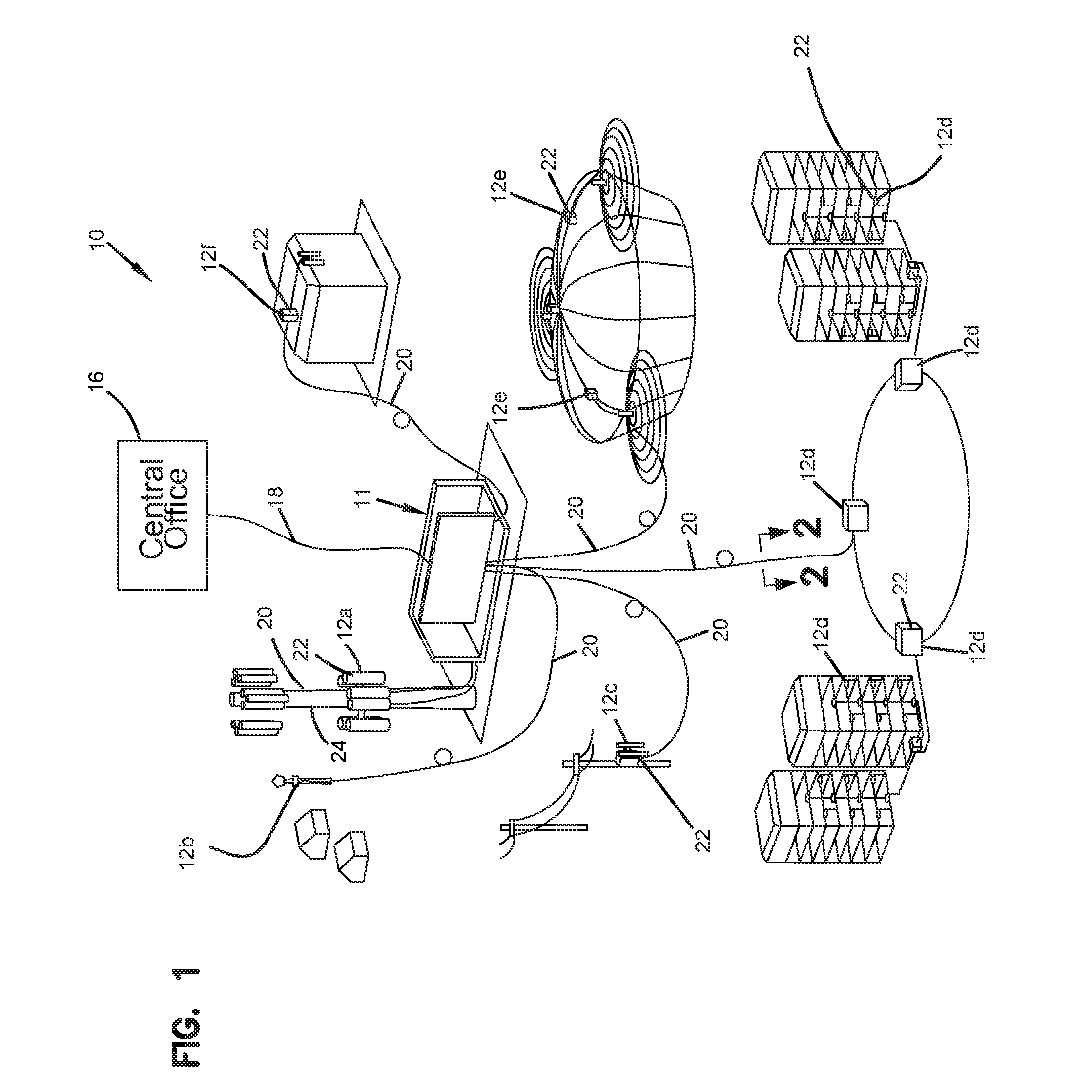
[0009] FIG. 1 is a system diagram showing an example distribution of wireless coverage areas deployed using a hybrid cable system in accordance with the principles of the present disclosure;
[0010] FIG. 2 is a transverse cross-sectional view of a power/optical fiber hybrid cable in accordance with the principles of the present disclosure, the cross-section taken along section line 2-2 of FIG. ;
[0011] FIG. 3 is a perspective view of a portion of the hybrid cable of FIG. 2 with electrically conductive portions of the cable showing separated from a central optical fiber portion of the cable;
[0012] FIG. 4 is a plan view of the hybrid cable of FIGS. 2 and 3 with the electrically conductive portions of the hybrid cable trimmed relative to the central fiber optic portion of the hybrid cable;
[0013] FIG. 5 is a transverse cross-sectional view of another power/optical fiber hybrid cable in accordance with the principles of the present disclosure;
[0014] FIG. 6 is a schematic representation of a system for manufacturing the hybrid cables in accordance with the principles of the present disclosure; and
[0015] FIG. 7 is a cross-sectional view taken along section line 7-7 of FIG. 6.
DETAILED DESCRIPTION
[0016] Various examples will be described in detail with reference to the figures, wherein like reference numerals represent like parts and assemblies throughout the several views. Any examples set forth in this specification are not intended to be limiting and merely set forth some of the many possible variations of the inventive aspects disclosed herein.
[0017] FIG. 1 shows a system 10 in accordance with the principles of the present disclosure for enhancing the coverage areas provided by cellular technologies (e.g., GSM, CDMA, UMTS, LTE, WiMax, WiFi, etc.). The system 10 includes a base location 11 (i.e., a hub) and a plurality of wireless coverage area defining equipment 12a, 12b, 12c, 12d, 12e and 12f distributed about the base location 11. In certain example, the base location 11 can include a structure 14 (e.g., a closet, hut, building, housing, enclosure, cabinet, etc.) protecting telecommunications equipment such as racks, fiber optic adapter panels, passive optical splitters, wavelength division multi-plexers, fiber splice locations, optical fiber patching and/or fiber interconnect structures and other active and/or passive equipment. In the depicted example, the base location 11 is connected to a central office 16 or other remote location by a fiber optic cable such as a multi-fiber optical trunk cable 18 that provides high band-width two-way optical communication between the base location 11 and the central office 16 or other remote location. In the depicted example, the base location 11 is connected to the wireless coverage area defining equipment 12a, 12b, 12c, 12d, 12e and 12f by hybrid cables 20. The hybrid cables 20 are each capable of transmitting both power and communications between the base location 11 and the wireless coverage area defining equipment 12a, 12b, 12c, 12d, 12e and 12f.
[0018] The wireless coverage area defining equipment 12a, 12b, 12c, 12d, 12e and 12f can each include one or more wireless transceiver 22. The transceivers 22 can include single transceivers 22 or distributed arrays of transceivers 22. As used herein, a "wireless transceiver" is a device or arrangement of devices capable of transmitting and receiving wireless signals. A wireless transceiver typically includes an antenna for enhancing receiving and transmitting the wireless signals. Wireless coverage areas are defined around each of the wireless coverage area defining equipment 12a, 12b, 12c, 12d, 12e and 12f. Wireless coverage areas can also be referred to as cells, cellular coverage areas, wireless coverage zones, or like terms. Examples of and/or alternative terms for wireless transceivers include radio-heads, wireless routers, cell sites, wireless nodes, etc.
[0019] In the depicted example of FIG. 1, the base location 11 is shown as a base transceiver station (BTS) located adjacent to a radio tower 24 supporting and elevating a plurality the wireless coverage area defining equipment 12a. In one example, the equipment 12a can define wireless coverage areas such as a macrocells or microcells (i.e., cells each having a coverage area less than or equal to about 2 kilometers wide). The wireless coverage area defining equipment 12b is shown deployed at a suburban environment (e.g., on a light pole in a residential neighborhood) and the equipment 12c is shown deployed at a roadside area (e.g., on a roadside power pole). The equipment 12c could also be installed at other locations such as tunnels, canyons, coastal areas, etc. In one example, the equipment 12b, 12c can define wireless coverage areas such as microcells or picocells (i.e., cells each having a coverage area equal to or less than about 200 meters wide). The equipment 12d is shown deployed at a campus location (e.g., a university or corporate campus), the equipment 12e is shown deployed at a large public venue location (e.g., a stadium), and the equipment 12f is shown installed at an in-building or near-building environment (e.g., multi-dwelling unit, high rise, school, etc.). In one example, the equipment 12d, 12e, and 12f can define wireless coverage areas such as microcells, picocells, or femtocells (i.e., cells each having a coverage area equal to or less than about 10 meters wide).
[0020] FIG. 2 is a transverse cross-sectional view taken through one of the hybrid cables 20 of FIG. 1. Hybrid cable 20 includes an outer jacket 100 having a transverse cross-sectional profile that defines a major axis 102 and a minor axis 104. The outer jacket has a height H measured along the minor axis 104 and a width W measured along the major axis 102. The width W is greater than the height H such that the transverse cross-sectional profile of the outer jacket 100 is elongated along the major axis 102.
[0021] The outer jacket 100 can include a left portion 106, a right portion 108 and a central portion 110. The left portion 106, the right portion 108 and the central portion 110 can be positioned along the major axis 102 with the central portion 110 being disposed between the left portion 106 and the right portion 108. The left portion 106 can define a left passage 112, the right portion 108 can define a right passage 114 and the central portion 110 can define a central passage 116. The passages 112, 114 and 116 can have lengths that extend along a central longitudinal axis 118 of the cable 20 for the length of the cable. A left electrical conductor 120 is shown positioned within the left passage 112, a right electrical conductor 122 is shown positioned within the right passage 114 and at least one optical fiber 124 is shown positioned within the central passage 116. The left electrical conductor 120, the right electrical conductor 122 and the optical fiber 124 have lengths that extend along the central longitudinal axis 118 of the cable 20.
[0022] Still referring to FIG. 2, the hybrid cable 20 includes a left pre-defined tear location 126 positioned between the central portion 110 and the left portion 106 of the outer jacket 100, and a right pre-defined tear location 128 positioned between the central portion 110 and the right portion 108 of the outer jacket 100. The left pre-defined tear location 126 is weakened such that the left portion 106 of the outer jacket 100 can be manually torn from the central portion 110 of the outer jacket 100. Similarly, the right pre-defined tear location 128 is weakened such that the right portion 108 of the outer jacket 100 can be manually torn from the central portion 110 of the outer jacket 100. The left pre-defined tear location 126 is configured such that the left portion 106 of the outer jacket 100 fully surrounds the left passage 112 and the central portion 110 of the outer jacket 100 fully surrounds the central passage 116 after the left portion 106 of the outer jacket 100 has been torn from the central portion 110 of the outer jacket 100. In this way, the left electrical conductor 120 remains fully insulated and the optical fiber 120 remains fully protected after the left portion 106 has been torn from the central portion 110. The right pre-defined tear location 128 is configured such that the right portion 108 of the outer jacket 100 fully surrounds the right passage 114 and the central portion 110 of the outer jacket 100 fully surrounds the central passage 119 after the right portion 108 of the outer jacket 100 has been torn from the central portion 110 of the outer jacket 100. In this way, the right electrical conductor 122 remains fully insulated and the optical fiber 124 remains fully protected after the right portion 108 has been torn from the central portion 110.
[0023] FIG. 3 shows the hybrid cable 20 with both the left portion 106 and the right portion 108 torn away from the central portion 110. In this configuration, both the left electrical conductor 120 and the right electrical conductor 122 are fully insulated by their corresponding left and right portions 106, 108. Additionally, the central portion 110 has a rectangular transverse cross-sectional shape that fully surrounds the central passage 116 so as to protect the optical fiber or fibers 124.
[0024] It will be appreciated that the left and right electrical conductors 120, 122 have a construction suitable for carrying electricity. It will be appreciated that the electrical conductors can have a solid or stranded construction. Example sizes of the electrical conductors include 12 gauge, 16 gauge, or other sizes.
[0025] The outer jacket 100 is preferably constructed of a polymeric material. In one example, the hybrid cable 20 and the outer jacket 100 are plenum rated. In certain examples, the outer jacket 100 can be manufactured of a fire-retardant plastic material. In certain examples, the outer jacket 100 can be manufactured of a low smoke zero halogen material. Example materials for the outer jacket include polyvinyl chloride (PVC), fluorinated ethylene polymer (FEP), polyolefin formulations including, for example, polyethylene, and other materials.
[0026] The central passage 116 can contain one or more optical fibers 124. In certain examples, the optical fibers 124 can be coated optical fibers having cores less than 12 microns in diameter, cladding layers less than 140 microns in diameter, and coating layers less than 300 microns in diameter. It will be appreciated that the core and cladding layers typically include a silica based material. In certain examples, the cladding layer can have an index of a refraction that is less than the index of refraction of the core to allow optical signals that are transmitted through the optical fibers to be confined generally to the core. It will be appreciated that in certain examples, multiple cladding layers can be provided. In certain examples, optical fibers can include bend insensitive optical fibers having multiple cladding layers separated by trench layers. In certain examples, protective coatings (e.g., a polymeric material such as actelate) can form coating layers around the cladding layers. In certain examples, the coating layers can have diameters less than 300 microns, or less than 260 microns, or in the range of 240 to 260 microns. In certain examples, the optical fibers 124 can be unbuffered. In other examples, the optical fibers can include a tight buffer layer, a loose buffer layer, or a semi-tight buffer layer. In certain examples, the buffer layers can have an outer diameter of about 800 to 1,000 microns. The optical fibers can include single mode optical fibers, multi-mode optical fibers, bend insensitive fibers or other fibers. In still other embodiments, the optical fibers 124 can be ribbonized.
[0027] As shown at FIG. 4, the left and right portions 106, 108 can be trimmed relative to the central portion 110 after the left and right portions 106, 104 have been torn away from the central portion 110. In this configuration, the central portion 110 extends distally beyond the ends of the left and right portions 106, 108. In certain examples, insulation displacement connectors can be used to pierce through the jacket materials of the left and right portions 106, 108 to electrically connect the left and right electrical connectors 120, 122 to an electrical power source, ground, active components or other structures. It will be appreciated that the optical fibers 124 can be directly terminated with optical connectors. In other examples, connectorized pigtails can be spliced to the ends of the optical fibers 124.
[0028] Referring back to FIG. 2, the outer jacket 100 includes a top side 130 and a bottom side 132 separated by the height H. As depicted, the top and bottom sides 130, 132 are generally parallel to one another. Each of the left and right pre-defined tear locations 126, 128 includes an upper slit 134 that extends downwardly from the top side 130, a lower slit 136 that extends upwardly from the bottom side 132 and a non-slitted portion 138 positioned between the upper and lower slits 134, 136. In one example embodiment, the upper and lower slits 134, 136 are partially re-closed slits. In the depicted embodiment, the left and right pre-defined tear locations 126, 128 also include jacket weakening members 140 that are imbedded in the non-slitted portions 138. By way of example, the jacket weakening members 140 can include strands, monofilaments, threads, filaments or other members. In certain examples, the jacket weakening members 140 extend along the central longitudinal axis 118 of the cable 20 for the length of the cable 20. In certain examples, the jacket weakening members 140 are aligned along the major axis 102. In certain examples, the upper and lower slits 130, 136 as well as the jacket weakening member 140 of the left pre-defined tear location 126 are aligned along a left tearing plane PL that is oriented generally perpendicular relative to the major axis 102. Similarly, the upper and lower slits 134, 136 as well as the jacket weakening member 140 of the right pre-defined tear location 128 are aligned along a right tearing plane PR that is oriented generally perpendicular with respect to the major axis 102.
[0029] Referring again to FIG. 2, the hybrid cable 20 can include a tensile strength structure 142 that provides tensile enforcement to the hybrid cable 20 so as to prevent tensile loads from being applied to the optical fibers 124. In certain embodiments, the tensile strength structure 142 can include reinforcing structures such as Aramid yarns or other reinforcing fibers. In still other embodiments, the tensile strength structure 142 can have an oriented polymeric construction. In still other examples, a tensile strength structure 142 can include a reinforcing tape. In certain examples, the reinforcing tape can be bonded to the outer jacket 100 so as to line the central passage 116. In certain examples, no central buffer tube is provided between the optical fibers 124 and the tensile reinforcing structure 142. In certain examples, the tensile strength structure 142 can include a reinforcing tape that extends along the length of the hybrid cable 20 and has longitudinal edges/ends 144 that are separated so as to define a gap 144 therein between. In use, the tensile strength member 142 can be anchored to a structure such as a fiber optic connector, housing or other structure so as to limit the transfer of tensile load to the optical fibers 124. It will be appreciated that the tensile strength structure 142 can be anchored by techniques such as crimping, adhesives, fasteners, bands or other structures.
[0030] FIG. 5 shows an alternative hybrid cable 20' having the same construction as the hybrid cable 20 except two tensile strength structures 142A, 142B have been provided within the central passage 116. Tensile strength members 142A, 142B each include a tensile reinforcing tape that is bonded to the central portion 110 of the outer jacket 100. The tensile strength members 142A, 142B can include portions that circumferentially overlap one another within the central passage 116. In certain examples, by stripping away an end portion of the central portion 110, the tensile strength structures 142A, 142B can be exposed and readily secured to a structure such as a fiber optic connector, a panel, a housing or other structure. In one example, the tensile strength structures 142A, 142B can be crimped, adhesively secured or otherwise attached to rods (e.g., epoxy rods reinforced with fibers) that are in turn secured within a ruggedized fiber optic connector such as the fiber optic connector disclosed at U.S. Pat. No. 7,744,288 which is hereby incorporated by reference in its entirety, or the fiber optic connector disclosed at U.S. Pat. No. 7,918,609, which is hereby incorporated by reference in its entirety.
[0031] It will be appreciated that cables in accordance with the principles of the present disclosure can be manufactured using a one-pass manufacturing process. In certain examples, the same one-pass manufacturing process can be used to manufacture different types of cables by substituting in different types of electrical conductors (e.g., stranded or non-stranded) and by using different types of optical fibers (e.g., buffered optical fibers, non-buffered optical fibers, ribbonized fibers, multi-mode fibers, single-mode fibers, bend insensitive fibers, etc.).
[0032] Referring to FIG. 6, a schematic representation of a system 200 for making the fiber optic cable 20 is shown. The system 200 includes a cross head, generally designated 202, that receives polymeric (e.g., thermoplastic) material from an extruder 204. A hopper 206 is used to feed material into the extruder 204. A conveyor 208 can be used to convey material (e.g., base material and possibly additives) to the hopper 206. In other embodiments, additional conveyors can be used to convey additional materials to the hopper 206. The extruder 204 is heated by a heating system 212 that may include one or more heating elements for heating zones of the extruder as well as the cross head 202 to desired processing temperatures.
[0033] One or more of the optical fibers 124 can be fed into the cross head 202 from one or more feed rolls 214. The system 200 can also include one or more supply rolls 218 for feeding the tensile strength structure 142 or structures to the cross-head 202 and a longitudinal shaping tool 220. The tensile strength structure 142 is disposed on the supply roll 218. The shaping tool 220 is used to form/shape the tensile strength structure 142 (e.g., one or more pieces of reinforcing tape) into a generally cylindrical shape that surrounds the one or more fibers 124 prior to entering the cross-head 202. The system 200 further includes feed rolls 250, 251 for feeding the electrical conductors 120, 122 into the cross-head 202, and feed rolls 254, 255 for feeding the jacket weakening members 140 into the cross-head 202.
[0034] A water trough 222 is located downstream from the cross head 202 for cooling the extruded product that exits the cross head 202. The cooled final product is stored on a take-up roll 224 rotated by a drive mechanism 226. A controller 228 can coordinate the operation of the various components of the system 200. The cross-head 202 can be configured to provide the jacket 100 with the desired transverse cross-sectional shape of FIG. 2. The system 200 further includes a slitting module 230 located immediately downstream from the cross head 202. The slitting module 230 includes blade slitting blades 232 that form slits in the outer jacket 100 corresponding to the upper and lower slits 134, 136. Preferably, the slitting blades 232 slit the outer jacket 100 while the material of the outer jacket is still at least partially molten. In this way, in certain examples, the slits at least partially reclose after slitting. In this way, the slits form weakened portions in the jacket. In other embodiments, the slits may remain fully open.
[0035] In use, the optical fibers 124, the left and right electrical conductors 120, 122, the tensile reinforcing structure 142 and the jacket weakening members 140 are all fed through the cross head 202. Prior to reaching the cross head 202, the shaping tool 220 can shape the tensile strength structure 142 around the optical fibers 120 such that the tensile strength member 142 surrounds the optical fibers as the optical fibers and the tensile strength structure 142 pass through the cross-head 202. As the components pass through the cross head, the material of the outer jacket 100 is extruded about the cylindrical tensile strength structure 142 as well as about the left and right electrical conductors 120, 122 and the jacket weakening members 140. In certain examples, the material forming the outer jacket 100 of the cable 20 leaves the cross-head 202 having a shape/profile of the type shown at FIG. 2. Thereafter, the cutting blades 232 of the slitting module 230 slit the upper and lower slits 134, 136 into the jacket. The cable is then cooled at the trough 222 and is collected on the take-up spool 224.
[0036] Various modifications and alterations of this disclosure will become apparent to those skilled in the art without departing from the scope and spirit of this disclosure, and it should be understood that the scope of this disclosure is not to be unduly limited to the illustrative examples set forth herein.
* * * * *
D00000
D00001
D00002
D00003
D00004
D00005
D00006
D00007
XML
uspto.report is an independent third-party trademark research tool that is not affiliated, endorsed, or sponsored by the United States Patent and Trademark Office (USPTO) or any other governmental organization. The information provided by uspto.report is based on publicly available data at the time of writing and is intended for informational purposes only.
While we strive to provide accurate and up-to-date information, we do not guarantee the accuracy, completeness, reliability, or suitability of the information displayed on this site. The use of this site is at your own risk. Any reliance you place on such information is therefore strictly at your own risk.
All official trademark data, including owner information, should be verified by visiting the official USPTO website at www.uspto.gov. This site is not intended to replace professional legal advice and should not be used as a substitute for consulting with a legal professional who is knowledgeable about trademark law.