Module-Driven Smartwatch
Yaghmour; Karim Jean
U.S. patent application number 16/179979 was filed with the patent office on 2019-05-09 for module-driven smartwatch. The applicant listed for this patent is Karim Jean Yaghmour. Invention is credited to Karim Jean Yaghmour.
| Application Number | 20190137947 16/179979 |
| Document ID | / |
| Family ID | 66327244 |
| Filed Date | 2019-05-09 |


View All Diagrams
| United States Patent Application | 20190137947 |
| Kind Code | A1 |
| Yaghmour; Karim Jean | May 9, 2019 |
Module-Driven Smartwatch
Abstract
The present disclosure provides several embodiments of a module-driven smartwatch. A leading aspect of a module-driven smartwatch is that it automatically reconfigures its user interface and experience based on the modules that are attached to it. In one embodiment, the module-driven smartwatch comprises a frontend processing unit powered by a primary battery and mainly configured for time-keeping and user-interfacing, a backend processing unit mainly configured for providing conventional "smartwatch"-like capabilities, and a module connector. In this embodiment, the backend processing unit's operation is contingent on power provided by a module connected to the module connector. In another embodiment, the module-driven smartwatch is much the same as a conventional smartwatch, except for its user interface and experience being driven by module attachment, operation and removal. In all cases, a module-driven smartwatch enables hardware extensibility and/or substitution without requiring smartwatch replacement.
| Inventors: | Yaghmour; Karim Jean; (Sherbrooke, CA) | ||||||||||
| Applicant: |
|
||||||||||
|---|---|---|---|---|---|---|---|---|---|---|---|
| Family ID: | 66327244 | ||||||||||
| Appl. No.: | 16/179979 | ||||||||||
| Filed: | November 4, 2018 |
Related U.S. Patent Documents
| Application Number | Filing Date | Patent Number | ||
|---|---|---|---|---|
| 62581773 | Nov 5, 2017 | |||
| Current U.S. Class: | 1/1 |
| Current CPC Class: | G06F 1/1658 20130101; G04G 21/02 20130101; G06F 13/409 20130101; G04G 17/06 20130101; G06F 1/1632 20130101; H01R 13/5219 20130101; G06F 1/163 20130101; G06F 1/3212 20130101; H01R 13/6271 20130101; H01R 13/6275 20130101; G04G 21/00 20130101; H01R 13/2471 20130101; G04G 17/04 20130101; G06F 13/00 20130101; H01R 13/24 20130101; G04G 21/04 20130101 |
| International Class: | G04G 17/04 20060101 G04G017/04; G06F 1/16 20060101 G06F001/16; G04G 17/06 20060101 G04G017/06; G04G 21/04 20060101 G04G021/04; G04G 21/02 20060101 G04G021/02; G06F 1/3212 20060101 G06F001/3212 |
Claims
1) A module-driven smartwatch comprising: a watch case; a display; an interface for receiving user input; means for being worn on a human body; a primary battery; at least one integrated circuit powered by the primary battery; and at least one module connector; wherein: the at least one integrated circuit is configured for: providing time-keeping capabilities; operating the display; and receiving user input from the interface; the at least one module connector is configure for: enabling modules to attach to the watch case; and providing electrical connectivity between a module and the at least one integrated circuit; and the at least one integrated circuit is configured for: interfacing with any module connected to the connector; and reacting to module connection by automatically: rearranging the display in a module-specific fashion; and responding to user input in a module-specific way.
2) The module-driven smartwatch of claim 1, wherein the module-driven smartwatch further comprises at least one additional integrated circuit configured for providing conventional smartwatch-like capabilities.
3) The module-driven smartwatch of claim 2, wherein the at least one additional integrated circuit mediates the interaction between the module and the at least one integrated circuit.
4) The module-driven smartwatch of claim 3, wherein the at least one additional integrated circuit is primarily powered through the module connector.
5) The module-driven smartwatch of claim 4, wherein the at least one integrated circuit is a low-power microcontroller and the at least one additional integrated circuit is a system-on-chip.
6) The module-driven smartwatch of claim 4, wherein the at least one additional integrated circuit is further connected to a secondary power source within the module-driven smartwatch.
7) The module-driven smartwatch of claim 4, wherein the at least one additional integrated circuit is connected to smartwatch-like peripherals.
8) The module-driven smartwatch of claim 1, wherein the at least one integrated circuit is configured for providing conventional smartwatch-like capabilities.
9) The module-driven smartwatch of claim 8, wherein the at least one integrated circuit is configured for: operating in a low-power state unless a module containing a battery is connected to the module-driven smartwatch; and utilizing power from the module containing a battery to exit low-power mode.
10) The module-driven smartwatch of claim 1, wherein the module-driven smartwatch is attached to a module comprising at least one module integrated circuit for interfacing with the at least one integrated circuit.
11) The module-driven smartwatch of claim 10, wherein the module further comprises a module battery for powering the at least one module integrated circuit
12) The module-driven smartwatch of claim 11, the module battery is configured for also supplying power to the MDS through the module connector.
13) The module-driven smartwatch of claim 12, the module-driven smartwatch further comprises at least one additional integrated circuit wherein: the at least one additional integrated circuit is configured for providing conventional smartwatch-like capabilities; and the at least one additional integrated circuit is primarily powered by the module battery.
14) The module-driven smartwatch of claim 13, wherein the at least one additional integrated circuit mediates the interaction between the module and the at least one integrated circuit.
15) The module-driven smartwatch of claim 14, the at least one additional integrated circuit is further connected to a secondary power source within the module-driven smartwatch.
16) The module-driven smartwatch of claim 10, wherein the module further comprises at least one additional integrated circuit primarily powered by the module battery and configured for providing conventional smartwatch-like capabilities.
17) The module-driven smartwatch of claim 16, the at least one additional integrated circuit mediates the interaction between the at least one module integrated circuit and the at least one integrated circuit
18) A module-driven smartwatch comprising: a frontend processing block; a backend processing block; frontend processing block peripherals; and an electrical connector; wherein: the frontend processing block is connected to the frontend processing block peripherals; the electrical connector is configured for interfacing with at least one module; the frontend processing block is connected to the backend processing block; the frontend processing block peripherals are configured for interfacing with the user; and the backend processing block is configured for: providing conventional smartwatch-like capabilities; operating its user interface through the frontend processing block; and interfacing with modules connected to the module-driven smartwatch through the electrical connector.
19) The module-driven smartwatch of claim 18, wherein the backend processing block is configured for instructing the frontend processing block to reconfigure its peripherals in a module-specific way upon module insertion.
20) The module-driven smartwatch of claim 19, wherein the backend processing block is configured for being primarily powered through the electrical connector.
21) The module-driven smartwatch of claim 20, wherein the module-driven smart further comprises a backend processing block-specific power source and the backend processing block is also connected to the backend processing block-specific power source.
22) A method for extending the hardware capabilities of module-driven smartwatch including at least one integrated circuit and at least one additional integrated circuit by way of using modules, the method comprising the steps of: providing a connector to enable modules to be connectable to the module-driven smartwatch; configuring the least one integrated circuit to provide time-keeping and user-interfacing capabilities; configuring the at least one additional integrated circuit to provide smartwatch-like capabilities; implementing an interfacing protocol between the at least one integrated circuit and the at least one additional integrated circuit; implementing an interfacing protocol between the at least one additional integrated circuit and a module attached to the connector; configuring the at least one additional integrated circuit to detect the connection of a module to the connector; and configuring the at least one additional integrated circuit to instruct the at least one integrated circuit to provide a module-specific user interface upon insertion of a module.
23) The method of claim 22, further comprising the steps of configuring the at least one additional integrated circuit to be primarily powered through the connector.
Description
[0001] This application claims priority to U.S. Application No. 62/581,773, titled "Module-Driven Smartwatch", filed on Nov. 5, 2017, the entire contents of which are herein incorporated by reference.
FIELD OF APPLICATION
[0002] The present disclosure relates generally to electronic devices and, more particularly, to what is commonly-known as "smartwatches."
BACKGROUND
[0003] For centuries, portable time-pieces were fabricated using mechanical gears and springs; first primarily as pocket watches and later, in the late 1800s and early 1900s, as wrist-worn watches. The 1970s saw the rise of electronic, quartz-based watches which, by the 1980s, had largely supplanted mechanical watches as the primary means for personal time-keeping. The 1970s and '80s also saw the rise of personal computing with the introduction of several key systems targeted at home buyers and individuals such as the Apple II.TM. and the IBM.TM. PC. Thus, since the 1970s, there have been several attempts at creating electronic watches that would combine some form of computerized capabilities along with time-keeping in the form of a wrist-worn device. At the time of this writing, such devices are commonly-referred to as "smartwatches". For the purposes of the present disclosure, a "smartwatch" is therefore a wrist-worn device providing some form of computerized capabilities along with time.
[0004] While the early smartwatches' capabilities were geared towards rudimentary data storage or calculator-like functionality, the 1990s and the early 2000s saw an increasingly wide array of computing-like capabilities being incorporated into smartwatches, including for example calendar and contact synchronization with users' computers. Still, for the most part such offerings and capabilities remained confined to niche markets. The last few years, however, have seen accelerated efforts by a large number of industry players, including very large consumer electronics vendors, to integrate into smartwatches many of the same features and/or technologies that have become mainstream as part of their inclusion in smartphones. At the time of this writing, for instance, there are therefore a large number of smartwatches on the market that combine features such as touch display, high-end processing capabilities, gyroscope, accelerometer, voice recognition, network connectivity through Bluetooth.TM., Wifi.TM. and/or cellular connection, etc.
[0005] The current crop of smartwatches, as they are promoted by most players in the industry, seem to be centered around the concept of providing highly-capable/integrated general-purpose smartwatches that enable software developers to tailor a smartwatch's use to provide a specific functionality to their user by way of developing a custom application that is loaded and run on the smartwatch. That is, most vendors are attempting to replicate the model popularized by smartphones where the user owns a highly-integrated device and uses different apps to accomplish different tasks on the same device. Such is the case for the smartwatches currently promoted by Apple.TM., as the Apple Watch.TM., and the different manufacturers that release smartwatches running Google's.TM. Android Wear.TM. operating system (OS).
[0006] In all those cases, the consumer is offered a self-contained, highly integrated smartwatch that combines all the electronics and the capabilities that the user could potentially need to run the software applications that are to be loaded onto their device using the application ecosystem their device belongs to, be it Apple's or Google's. Much like the smartphone ecosystems, the differentiation between such smartwatches is therefore based on the full list of technical specifications available at the time the watch is manufactured. This therefore typically means that the watch contains more hardware than the user effectively needs at any point in time since most apps tend to require only a subset of the overall capabilities of the smartwatch, and the user generally uses only a single or a very limited number of apps at most at the same time. Conversely, should new hardware features be required or introduced, or older features be upgraded, the consumer is expected to purchase a new smartwatch. Given that such smartwatches can be relatively expensive, it can be difficult for users to justify a replacement cycle similar to that found in the smartphone market, especially since, unlike smartphones, the purchase of a smartwatch is unlikely to be bundled in their carrier's customer plan.
[0007] More importantly, outside the realm of use-case-specific smartwatches, such as for example fitness/exercise-tracking and health-monitoring, like the Fitbit.TM. and Garmin.TM. line of fitness trackers, the appeal of general-purpose smartwatches incorporating many smartphone-like capabilities in a smaller form-factor remains limited. Several reasons have been circulating within the industry to explain this, namely:
Limited battery life Tiny screen size Constrained entry capabilities Dependence on smartphone: requires a smartphone to function and/or requires a specific make/model to function Dependence on the cloud Size and weight Reliability of measurements Each of these is further discussed in detail below.
[0008] One of the primary issues with smartwatches is their limited battery life. Indeed, some watches, such as the Apple Watch and many Android Wear-based watches need to be charged on a daily basis. Some smartwatches fare a bit better and only require a charge every week, with some even lasting for as long as 10 days. Such is the case for some Garmin models, the now defunct Pebble and the Qualcomm Toq concept smartwatch. Still, even at those rates, no smartwatch fitting the current definition gets anywhere near the longevity provided by classic quartz-based watches which can last for more than a year, sometimes several years, on a single coin-cell battery. Even early 1980s smartwatches, such as the Seiko UC-2000 and Data-2000 could last at least several months without requiring a battery change. Such watches did not obviously have the same feature-set as present-day smartwatches, but they did however provide the user with the primary functionality they were wearing the device for: having the time available on their wrist at all times.
[0009] There are several reasons why modern-day smartwatches' batteries require constant charging. One of the main reasons is that, as alluded to earlier, manufacturers design smartwatches to be highly integrated devices such as smartphones. Hence, smartwatches end up containing several dozen specialized hardware components to cater for every conceivable use-case the manufacturer believes the smartwatch is meant to address. Every such component and/or integrated circuit requires battery power. Each component individually may not draw a lot of power, but combined together the components overall draw more than can be accommodated for a very long duration by a battery of the size that can fit in a smartwatch. That's especially true if the user starts using apps on their watch that bring some components out of their quiescent state and into full power mode where they consume even more power than when they are unused.
[0010] Another reason why smartwatch batteries tend to not last very long is that most manufacturers operate on the assumption that users want to have the same kind of high-definition color display that is found on smartphones. Such displays, especially ones that are readable in high ambient light conditions, such as sunlight, are very power hungry. As such, most manufacturers attempt to put in place several optimizations that keep those displays' power consumption at a bare minimum for most of the time. Some keep the displays off until a certain wrist movement is operated by the user, thereby triggering the display to come on and provide the time. Other manufacturers put the display in a low power consumption mode where the time is faintly visible, thereby making it possible for the user to consult the time at all times, but then turning the display fully on when the user is actually interacting with the device. Yet another optimization implemented on smartwatch platforms is to use darker display backgrounds for most screens since white backgrounds are more power hungry. While such tricks are interesting optimizations, they remain insufficient to meaningfully extend smartwatches' operation.
[0011] It remains that the physical space inside a smartwatch is limited and, as was mentioned earlier, this limits the size and therefore the capacity of a battery. Traditional coin-cell batteries that can fit in a regular quartz watch can traditionally store up to around 200 mAh. Rechargeable LiPo batteries such as those found in smartwatches can be around 200 to 300 mAh, or sometimes a bit more. In contrast, it's not uncommon to find smartphones with an order of magnitude more of battery capacity. Hence the typical approach taken at the time of this writing by smartwatch manufacturers of trying to fit many of the features found in smartphones into the much smaller smartwatch form-factor practically guarantees that the lack of battery capacity will be an irritant to users.
[0012] Another issue with smartwatches is the limited size of their screens. Indeed, by trying to mimic an app experience similar to that of smartphones but on users' wrists, manufacturers and designers end up having to find convoluted ways to display vasts amounts of information and/or app navigation interactions on a very tiny screen real-estate. The fact is that current smartwatches being general-purpose devices, the user must first typically navigate through the tiny screen to the app they wish to interact with before they can then proceed to launching the app and benefiting from its functionality.
[0013] Not only does the limited screen size make the navigation to the app difficult, but it also limits the possible interactions with the app itself. Indeed, apart from the predefined gestures and capabilities provided by the platform on which the app runs on and the existing buttons found on the smartwatch, an app cannot provide any other way of interacting with it to the user. Instead, since many smartwatch apps act as companion modules to smartphone apps, the smartphone app is designed to contain the full set of functionality whereas the companion smartwatch app contains only a limited subset of the overall functionality, the complete set being only available to the user when operating the app from their smartphone.
[0014] A further limitation of smartwatches is their dependence on users' phones in order to operate properly and/or provide their full feature set. Indeed, up to very recently, the Apple Watch and Android Wear required direct tethering to a smartphone in order to operate. More recent versions of those systems have included the ability to operate without being directly tethered to a smartphone, but much of their functionality remains predicated on the user's smartphone as described earlier. Some smartwatch models, such as the Apple Watch, cannot be operated using anything but a matching smartphone make and/or model, an iOS phone in the case of the Apple Watch. This too is an inconvenience to users who are forced to choose a fixed combination of hardware products instead of being able to selectively choose which product best matches their needs.
[0015] Another common dependence for smartwatches is the requirement to use the app ecosystem and/or cloud services matching the operating system (OS) running on the smartwatch. Indeed, both Apple's watchOS.TM. and Android Wear depend on the respective cloud services to operate. It's either inconvenient or impossible for a user to operate their smartwatch independently of those cloud services. This too is a limitation to users' freedom as they cannot fully freely operate their smartwatch using the services of their choice.
[0016] Another issue with some modern-day smartwatches is their size and weight. Indeed, given the high level of integration found in smartwatches, there are a great deal many components packaged into a single constrained housing. Furthermore, given the battery issues mentioned earlier, smartwatch rechargeable batteries must contain enough capacity to provide an acceptable experience to the user. Effectively, this means that the batteries for smartwatches containing powerful hardware must be physically large, therefore contributing to the size and weight of smartwatches. While such issues are subjective, it remains that the level of integration and battery requirements dictated by current designs create a situation where it's difficult to minimize the size without sacrificing functionality.
[0017] Yet another issue with some smartwatches and fitness trackers is that the measurements they provide regarding activity tracking can be somewhat unreliable. Indeed, some cursory investigations by trade press have found that some of the information reported by smartwatches can be misleading. Since smartwatches are integrated devices with non-interchangeable parts, it's therefore impossible to remedy this situation once the device has shipped, unless the issue was in software only. If the issue is due to hardware, the only solution for users is to replace the smartwatch.
[0018] While several of the above issues with smartwatches remain unanswered by the current market offerings, it isn't the present disclosure's purpose to necessarily address them all or the entirety of those it attempts to address. The aforementioned issues are presented here to provide the background and contemporaneous context of the present disclosure.
[0019] There is thus a need for a smartwatch that does not necessarily attempt to include all hardware required for every potential use case within a highly-integrated, general-purpose design.
[0020] There is therefore a need for a smartwatch whose hardware can be extended and/or modified after it is manufactured.
[0021] There is therefore also a need for a smartwatch whose design prioritizes battery life over integrated functionality.
[0022] There is thus also a need for a smartwatch that ensures that time can be displayed to the user for an extended period of time without necessitating battery replacement or recharging.
[0023] There is therefore further a need for a smartwatch that enables the minimizing of on-screen navigation and interaction to obtain a certain functionality.
[0024] There is therefore also a need for a smartwatch that provides interaction mechanisms and/or design elements that are tailored for the form-factor limitations of and variations afforded by a wrist-worn device.
[0025] There is additionally a need for a smartwatch whose weight can be optimized by reducing the quantity of components integrated within the confines of its limited housing.
[0026] There is therefore further a need for a smartwatch built around a hardware architecture that enables a certain degree of functionality replacement and extensibility.
SUMMARY OF THE INVENTION
[0027] An object of the present disclosure is to provide a module-driven smartwatch that overcomes at least one of the previously-listed drawbacks and that satisfies at least one of the above-mentioned needs.
[0028] Another object of the present disclosure is to provide a module-driven smartwatch that relies primarily on interchangeable modules in order to provide task-specific functionality.
[0029] According to the present disclosure, there is provided a module-driven smartwatch that:
[0030] provides basic watch-like (time-keeping) capabilities such as time, date, and alarm;
[0031] is capable of providing computerized capabilities; and
[0032] is connectable to at least one module;
[0033] wherein the computerized capabilities are active primarily, though not exclusively, when an at least one module is connected to the module-driven smartwatch.
[0034] According to the present disclosure, there is further provided a method for providing function-specific capabilities to a smartwatch by way of using modules.
[0035] It is hereby noted that for brevity purposes, both the figures used in the present disclosure and the following text use the acronym "MDS" instead of "module-driven smartwatch". All instances of "MDS" should therefore be read in context as "module-driven smartwatch". For example, "MDS module" stands for "module-driven smartwatch module". Furthermore, note that the use of expressions such as "current-day", "contemporary", "conventional", "traditional", "regular" or any similar term in relation to the term "smartwatch" refers to the state of the art, the market offerings and the technologies most widely prevalent with regards to smartwatches at the time of the writing of the present disclosure.
[0036] In one embodiment, an MDS is preferably, but not necessarily, a wrist-worn device whose primary function is to provide time while being capable of advanced, current-day smartwatch-like capabilities when a module is attached to it. Therefore a distinction between a conventional smartwatch and one of the embodiments of the MDS could be that the former's computerized capabilities are effectively available at all times whereas the latter's computerized capabilities would be meant to only be available when a module is connected. This wouldn't preclude those computerized capabilities from being enabled at other times for limited amounts of time and/or with proper power being supplied to the module and/or MDS, but it would contrast with current-day smartwatches where computerized capabilities are meant to be available almost at all times, typically when the user interacts with the smartwatch or when some form of notification occurs. In other words, the normal operation of one of the embodiments of the MDS could be that its computerized capabilities would typically, but not necessarily, be enabled as a result of the connection of a module and disabled on the module's disconnection. Said computerized capabilities could also be enabled exceptionally under other circumstances for this embodiment of the MDS, including following user interaction. Such enabling would, however, be considered an infrequent or uncommon use-case for such an embodiment of the MDS.
[0037] In such an embodiment, at its most basic level, the MDS would contain the necessary hardware and components to function as a basic watch for a prolonged period of time without requiring frequent battery recharging nor replacement. In other words, this embodiment of the MDS could typically, but not necessarily, provide time for several weeks, months or years at a time, in contrast with current smartwatches that can only hold power for several hours or days at a time. Such basic watch-like functionality would not preclude this embodiment of the MDS from having some form of computerized capabilities in addition to the watch-like functionality when a module is not connected to it, but those computerized capabilities would be typically, but not necessarily, fairly constrained and insufficient to provide what users would generally recognize as comparable to a current-day smartwatch. In this same embodiment, the MDS would also contain the required hardware to enable advanced smartwatch-like capabilities and functionality to be provided to the user upon the attachment and/or pairing of a module.
[0038] In another embodiment, the MDS may function as a regular fully-featured, always-on/always-active smartwatch with modules providing function-specific capabilities. The details outlined earlier and below would remain similar but there wouldn't necessarily be the need to divide or qualify the MDS' functional capabilities into different degrees based on the present or absence of a module. Such a smartwatch would likely have some of the same drawbacks as conventional smartwatches, such as short overall battery life, but it would have many of the benefits and/or features of the module-driven approach described in the present disclosure.
[0039] Modules can be function-specific and enable functionalities such as providing:
incoming notifications from smartphone fitness tracking remotely-accessible storage music playback through either Bluetooth or an audio jack audio recording via a microphone sleep tracking health tracking (heartbeat, pulse oximeter, etc.) cellular connectivity camera capabilities gluco-meter capabilities bar-code or QR-code reading user-customizeable or user-extendable capabilities (for makers for example) Many other functions may also be envisioned and provided as modules. Modules may also combine several functionalities together. This, therefore, could enable the creation of general-purpose modules that externalize some or much of the capabilities typically bundled inside a traditional smartwatch. In some configurations it may even be desirable for modules to be stackable, thereby enabling multiple modules to be connected together.
[0040] Modules may additionally include connectivity capabilities including, but not limited to, Bluetooth, Wifi, GSM, CDMA, GPS, NFC, RFID, IrDA, mesh networking or any other kind of radio frequency (RF)-, audio frequency-, electromagnetic spectrum-, or, more generally, wireless-enabled connectivity. Wired connectivity capabilities could also be included in modules thereby enabling the MDS to connect to further forms of communication. Examples of such wired connections include, but are not limited to, general-purpose connections such as USB (with the MDS being either host and/or device), Ethernet, RS232, eSATA, HDMI, DisplayPort, audio jack, or Thunderbolt, special-purpose connections such as SPI, I2C, GPIO, PWM, UART, CAN bus, or even a custom wired connection type. The MDS may also include several types of connectors for attaching several types of peripherals. The MDS may, for example, have slots to attach a MicroSD card or a SIM card or any other similarly-typed device.
[0041] Modules may also simply be a battery that provides sufficient power to the MDS, possibly to enhance or enable its smartwatch-like capabilities. Function-specific modules may also include a battery to power the module itself and/or the MDS in order to provide the functionality embodied in the module. A notification module, for instance, may comprise Bluetooth connectivity and a battery. The battery would provide the power necessary for the module to pair with the user's smartphone over Bluetooth as well as the power required for the MDS to receive, display and manage notifications for the user. A module, regardless of its type, may or may not therefore necessarily include a battery.
[0042] Module and MDS power may also be provided by other means than just battery. Indeed, power may be provided by way of the module and/or MDS being connected to a PC over USB, using kinetic movement, by way of a supercapacitor or any other means for providing power. Furthermore, the MDS may contain one or several internal power-storing and/or power-capable components such as a battery, a supercapacitor or a wrist-mouvement-powered generator. Each of these may also supplement the other. A wrist-mouvement-powered generator may, for instance, be used to recharge a battery and/or a supercapacitor found within the MDS. An MDS' supercapacitor may also be charged by a module's battery.
[0043] Modules containing batteries would preferably, but not necessarily, be rechargeable independently of the MDS. Once a Bluetooth-enabled notification module has been used for an entire day, for instance, the user may disconnect said module from the MDS and place it on a charger until the following morning. The user does not necessarily need to remove their MDS from their wrist to accomplish this. Instead, the MDS continues to provide time while the disconnected module is getting charged. The user can then reconnect the recharged module at their convenience or choose to connect another already charged module. By having several identical modules, for instance, a user may even be able to have uninterrupted access to the functionality provided by said module by cycling through a series of fully-charged module units. Such would be the case, for example, with several units of a notifications module which could be cycled through to provide constant notification capabilities without ever requiring the user to take the smartwatch off their wrist to recharge it. A recharged module may also serve to recharge an internal, unremovable battery or supercapacitor found inside the MDS.
[0044] The module may be physically-attached directly to the MDS or it may be physically separate while being remotely paired via some form of wireless protocol. Many forms of physical connectivity may be envisioned such as will be described in further detail below. It remains that a given functionality is not available on the MDS until a corresponding module providing support for that functionality is connected to the MDS, regardless of the means used to establish that connection. The MDS therefore has means for enabling the connection to modules. Said means may include direct physical connectors, connectors that operate at close proximity or wireless connections such as, but not limited to, those listed earlier.
[0045] In one embodiment, the MDS preferably, but not necessarily, wouldn't operate as a smartwatch until a module is attached to it. Given current battery technology, this would therefore ensure the MDS power is preserved to provide classic watch capabilities over a long period of time. However, this would not preclude some of the aforementioned module functionality to be included within the MDS while still the latter is module-driven. This is likely to be useful if a given functionality is required for several modules. For example, if several modules require Bluetooth then including this functionality in the MDS avoids having each module to include it as well. Still, in this embodiment the Bluetooth functionality found in the MDS for modules would only be active when a module is attached and/or connected to the MDS. This would not, however, preclude the MDS from having Bluetooth functionality for other purposes unrelated to modules, such as for providing Bluetooth functionality while no module is connected.
[0046] In another embodiment, the MDS would operate as a regular or conventional smartwatch regardless of whether a module is attached or not. The attachment of a module would enable the user to benefit from the additional functionality provided by the module, or potentially extended battery life in the case of a module comprising a battery, but the smartwatch capabilities of the MDS would be available at all times.
[0047] In typical embodiments, when a module providing a specific functionality is connected to the MDS, the MDS preferably, but not necessarily, immediately and/or automatically displays the information related to that module's capabilities on the MDS' display. If the module is for tracking fitness, for instance, then attaching it results in the MDS then showing fitness tracking information from the module in addition to or instead of the current time. The user can then start interacting with the MDS for the specific functionality provided by the then-just-connected module. This may mean that the user can then use the MDS' buttons and/or other controls to interact with a module-specific interface and/or contextual menu and/or paradigm. Preferably, but not necessarily, the user does not have to navigate a user interface to get to the controls and/or interface associated with a connected module. Instead, they are preferably, but not necessarily, made readily available to the user as the module is connected.
[0048] Modules may also provide additional user-experience opportunities than those defined by or found in the MDS. A module may, for instance, have additional buttons, knobs, LEDs, or even displays separate from the MDS. This therefore enables module manufacturers to customize their modules' user experience capabilities without being limited by the features found in the MDS.
[0049] Other features of the presently disclosed computing device and method will become apparent from the following detailed description taken in conjunction with the accompanying drawings, which illustrate, by way of example, the presently disclosed electronic device and method.
BRIEF DESCRIPTION OF THE DRAWINGS
[0050] A detailed description of preferred embodiments will be given herein below with reference to the following drawings, in which like numbers refer to like elements:
[0051] FIG. 1 is one of the embodiments of a module-driven smartwatch.
[0052] FIG. 2 illustrates several module embodiments.
[0053] FIG. 3 is one embodiment of a module-driven smartwatch with connectors on both sides.
[0054] FIG. 4 is one embodiment of a module-driven smartwatch with stackable modules.
[0055] FIG. 5 illustrates one module embodiment with a strap or band.
[0056] FIG. 6 illustrates module-driven smartwatch display examples.
[0057] FIG. 7 is a side projection of one of the embodiments of a module-driven smartwatch and one embodiment of a module
[0058] FIG. 8 is a module-driven smartwatch embodiment showing built-in module slots.
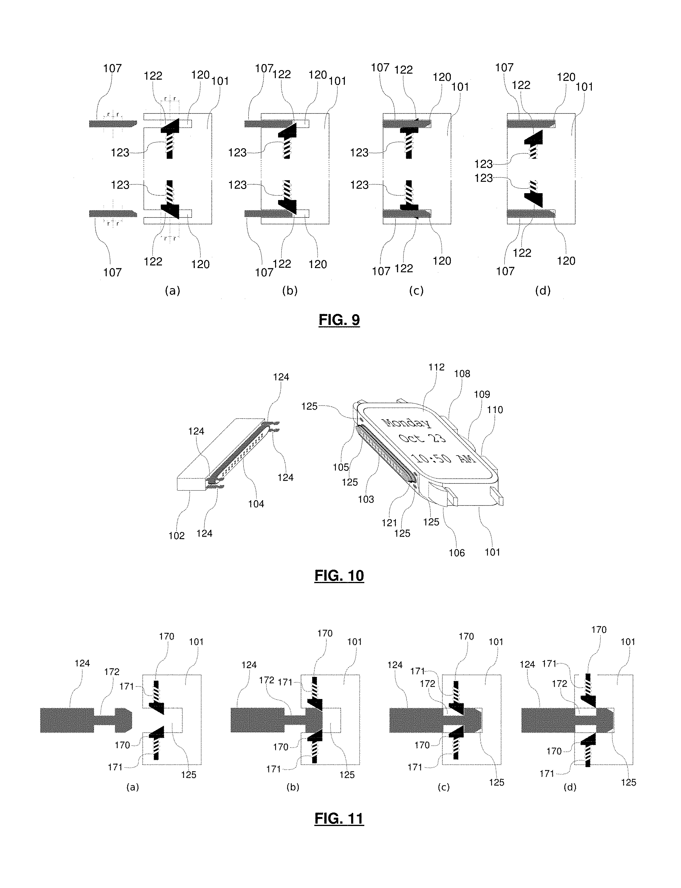
[0059] FIG. 9 is a detailed cross-section view of a latching mechanism embodiment.
[0060] FIG. 10 is an alternate embodiment of a mechanical locking mechanism.
[0061] FIG. 11 is a detailed cross-section of an alternate locking mechanism embodiment.
[0062] FIG. 12 illustrates an electrical connectors embodiment front view.
[0063] FIG. 13 illustrates an electrical connectors embodiment cross-section.
[0064] FIG. 14 illustrates an alternate electrical connectors embodiment cross-section.
[0065] FIG. 15 illustrates a module charging station box.
[0066] FIG. 16 is a simplified block diagram of one of the embodiments of a module-driven smartwatch and a corresponding module.
[0067] FIG. 17 is a simplified block diagram of another embodiment of a module-driven smartwatch and a corresponding module.
[0068] FIG. 18 is a simplified block diagram of yet another embodiment of a module-driven smartwatch and a corresponding module wherein the module-driven smartwatch operates are a regular smartwatch whether or not a module is attached to it.
[0069] FIG. 19 is a block diagram with hardware and software blocks for one of the embodiments of a module-driven smartwatch and a corresponding module.
[0070] FIG. 20 is a block diagram with hardware and software for another embodiment of a module-driven smartwatch and a corresponding module.
[0071] FIG. 21 is a block diagram with expanded communication paths for one of the embodiments of the a module-driven smartwatch and a corresponding module.
[0072] FIG. 22 is a block diagram with hardware and software for another embodiment of a module-driven smartwatch and a corresponding module wherein the module-driven smartwatch operates are a regular smartwatch whether or not a module is attached to it.
[0073] FIG. 23 is a hardware block diagram for one of the embodiments of a module-driven smartwatch and a corresponding module.
[0074] FIG. 24 is a hardware block diagram of one embodiment of a module-driven smartwatch comprising a backend power source and a corresponding module.
[0075] FIG. 25 is a hardware block diagram of another embodiment of a module-driven smartwatch and a corresponding module wherein the backend is in the module.
[0076] FIG. 26 is a hardware block diagram of yet another embodiment of a module-driven smartwatch and a corresponding module wherein the backend processing block is comprised in the frontend processing block.
[0077] FIG. 27 is a hardware block diagram of another embodiment of a module-driven smartwatch and a corresponding module wherein the module-driven smartwatch operates are a regular smartwatch whether or not a module is attached to it.
[0078] FIG. 28 is a detailed view of a backend processing block embodiment.
[0079] FIG. 29 is a detailed view of another backend embodiment.
[0080] FIG. 30 is a detailed view of a frontend processing block embodiment.
[0081] FIG. 31 is a detailed view of another frontend embodiment.
[0082] FIG. 32 is a detailed view of an embodiment of a module-driven smartwatch and a module wherein the module-driven smartwatch operates are a regular smartwatch whether or not a module is attached to it.
[0083] FIG. 33 is a detailed view of a module processing block embodiment.
[0084] FIG. 34 is a detailed view of another module processing block embodiment.
[0085] FIG. 35 illustrates a module attachment sequence example.
[0086] FIG. 36 illustrates an example of generic information flow across main system blocks.
[0087] FIG. 37 illustrates another information flow example across main system blocks.
[0088] FIG. 38 illustrates a module detachment sequence example.
[0089] FIG. 39 is an example overall information flow, including external systems.
[0090] FIG. 40 is an example overall information flow for a fitness module, including external systems.
[0091] Note that many diagrams are based on material provided in the public domain at openclipart.org. Note also that Trademarks belong to their respective owners. Trademarks in this document are first-letter capitalized.
DETAILED DESCRIPTION OF THE PREFERRED EMBODIMENTS
[0092] FIG. 1 illustrates one embodiment of a MDS 101 before (FIG. 1 (a)) and after (FIG. 1 (b) and (c)) it is connected to a module 102. The MDS 101 and the module 102 are connected both electrically and mechanically. FIG. 1 illustrates one connector set configuration. Several other electrical and mechanical connectors can be envisioned without departing from the teachings of the current disclosure. In fact, magnetic and/or capacitive and/or other types of connectors could also be used in conjunction with or in replacement of the connectors described in the present disclosure without departing from its teachings. In FIG. 1 (a), the MDS' electrical connector 103 is shown as aligned to mate with the module's electrical connector 104. The size, shape and specific signals carried through these connectors can change significantly without departing from the teachings of the current disclosure. An example electrical connector set will be presented in detail below. FIG. 1 (a) also illustrates part of one embodiment of a mechanical connector mechanism that can be used to connect the MDS and a module. Specifically, FIG. 1 (a) illustrates the mechanical connector lips 107 found in one module 102 embodiment and usable to hold the module in place using spring-loaded latch pins found in this embodiment of the MDS 101 and described later.
[0093] While FIG. 1 illustrates the connector sets as being located on the left-hand side of the MDS 101, it's entirely possible for other configurations to be used. The connectors may be located on the right-hand side instead. They may also be located at the front (where the display and glass or "crystal" are typically located) or the back (which is typically the part of the watch touching the user's skin) sides of the watch 101. Modules may also be made to be connectable underneath, on front or inside the MDS 101 instead of or in addition to any of its four sides. The specific location and/or configuration and/or the types of connectors used between modules and the MDS 101 can vary significantly without departing from the teachings of the present disclosure.
[0094] The rest of the MDS 101 resembles the parts of existing watches. Namely it preferably, but not necessarily, has buttons 108, 110 and possibly other forms of physical user input such as thumbwheels 109 or possibly a conventional watch crown. The MDS 101 may also optionally enable touch user input using capacitive, resistive or other such types of technologies. The MDS 101 may also additionally feature gesture-based input as well as voice recognition technology, or any other interface for receiving user input. Buttons and other physical entry means may also be on the front of the MDS 101 instead of on its side. The MDS' display 112 is show in FIG. 1 as being square and digital. The MDS 101 may however feature a round display and may also use conventional rotating watch hands to display time, whether the housing itself is square, round or of another shape entirely. The specific shape of the MDS 101 and/or its display 112, and the technology used to display information on the MDS 101 may vary greatly without departing from the teachings of present disclosure. The display 112 may, in fact, be a conventional LCD such as those found in 1980s digital watches. The MDS 101 typically, but not necessarily, uses a conventional wrist strap or band 111 to attach to a user's wrist. Such a strap or band 111 may be attached to the MDS 101 using conventional watch lugs or be attached to the MDS 101 through a recessed space within the watch's body. The MDS 101 may however rely on any other means used by any other watch in the market for attaching to a user's wrist or body.
[0095] To connect a module 102 to the MDS 101, in the case of the connector embodiment illustrated in FIG. 1, the user aligns the module's connectors 104, 107 with the MDS' connector 103 and starts sliding the module 102 towards the MDS 101. Once the connector sets have started making physical contact, the user continues to slide the module 102 towards the MDS 101 until the spring-loaded latch pins found in the MDS trigger (i.e. lock onto the module's mechanical connector lips 107), thereby locking the module 102 in place. To release the module 102 from the MDS 101 in the case of illustrated module connector embodiment, the user presses the release buttons 105, 106, thereby causing the spring-loaded latch pins found in the MDS to retract, thereby releasing the module 102. Springs could also be added to the MDS 101 to gently push the module 102 away from the MDS 101 once it is released. Other release mechanisms can be envisioned other than the buttons illustrated in FIG. 1 without departing from the teachings of the current disclosure. Instead of relying on physical buttons, for instance, release requests could also be made using the MDS' user interface. Software running on the MDS 101 would then instruct hardware to release the module 102 using some form of hardware-triggered mechanism.
[0096] Preferably, but not necessarily, once the module 102 is connected, as shown in FIG. 1 (b), all connectors are hidden from view and the MDS' display 112 changes to display module-specific information. In the case of FIG. 1 (b), the MDS displays notification information 113 showing the number of missed calls and new emails. The rearrangement of the display 112 once a module 102 is plugged in can vary quite substantially without departing from the teachings of the present disclosure. A module 102 may also provide many other functionalities than just notifications, as outlined in the previous section. FIG. 1 (c), for example, illustrates a fitness tracking module 114 attached to the MDS 101. In this case, the MDS' display 112 changes to display fitness tracking information 115. In addition to displaying module-specific information, the MDS 101 preferably, but necessarily, provides module-specific interaction functionality through its user input capabilities (including, but not limited to, 108, 109, 110) such as menus and dialogs.
[0097] FIG. 2 illustrates several example modules. FIG. 2 (a) illustrates a module 140 with two buttons on its left-hand side 151, 152. Such additional buttons could be used to provide needed module-specific interaction beyond that possible through the MDS' own input capabilities. FIG. 2 (b) illustrates a module with a slightly-protruding height 141 equipped with a pivoting antenna 153. This may be useful for specialized radio use-cases. FIG. 2 (c) illustrates a module 142 with a connector on its topside 154 and a battery gauge 155. Such a module could be used to enable the MDS to connect to a computer/PC over USB for data syncing and/or sharing in addition to using USB power to charge the module while it's connected to the MDS. FIG. 2 (d) illustrates a slightly-wider module 143. Such modules may be useful in case the hardware required to implement a module requires a larger printed circuit board (PCB) and/or if the module houses a larger battery. FIG. 2 (e) illustrates a module 144 with an additional display 161 along with buttons on its front side 159, 160. An additional display, or other means of conveying visual information such as LEDs, could enable modules to provide a user experience tailored to the use-case addressed by the module. Front buttons could serve as another means of physical input which may be more relevant in some contexts. FIG. 2 (f) illustrates a module 145 that features conventional rotating watch movements 156, 157 with one movement showing hands for hours, minutes, seconds 156 and the other showing a single rotating hand 157, possibly for chronograph use. This module 145 also features a crown 158 on its left-hand side. Other module variations can also be envisioned without departing from the teaching of the present disclosure.
[0098] FIG. 3 (a) illustrates an MDS 101 with connectors on both the left 103 and right-hand side 118. Consequently, such an MDS 101 would also preferably, but not necessarily, feature release buttons for the right-hand side module 116, 117. FIG. 3 (b) illustrates the previously-shown fitness tracking module 114 connected to the left connector. Additionally, it illustrates a button module 119 which replaces the built-in buttons from the previous figures. The right-hand side connector could be used to connect any module that would be connectable to the left-hand side connector, albeit the design may have to take into account that the module would be rotated by 180 degrees. The MDS 101 could also be worn on either the right or left hand wrists.
[0099] FIG. 4 illustrates a configuration where modules would be stackable side-by-side 163, 162. This would allow connecting several modules together simultaneously to the MDS. To accommodate this possibility, certain modules 162 would need to have connectors on both sides in order to enable other modules to connect to them as well. While there wouldn't necessarily be a limit to the number of modules that could be stacked, it would be for the user to determine how many modules they are willing to wear simultaneously while still finding the usability manageable. Either way, the MDS could have the capabilities to allow the user to select which module's information and/or user interface is to be displayed at any point in time.
[0100] FIG. 5 illustrates a configuration where a module 164 also has a strap or band in addition to the MDS. This would provide additional support for the module either for user convenience or for design reasons. If a module is too heavy relative to the MDS 101, for instance, it may be useful to hold the module in place directly. A module 164 may also be attached in some way to the MDS' strap or band in some circumstances.
[0101] FIG. 6. illustrates several possible displays for the MDS. (a) through (c) are featured in previous figures. (d) illustrates a display showing music playback. (e) and (f) are conventional mechanical watch hand movements with (f) showing notifications in addition to time. Such a display may be rendered on-screen using an LCD or it could in fact be made using conventional watch parts such as actual moving mechanical hands or a combination of both. (g) and (h) also feature mechanical watch movement-like time along with module-specific information. (g) shows the same fitness-tracking information shown earlier. (h) shows a combination of notifications and fitness tracking information, possibly given the attachment of a module providing both functionalities.
[0102] Note that the specific information displayed for any given module can vary greatly from the examples shown. There is nothing precluding a fitness module to display more information than just the number of steps and calories presented in the previous figures, or for notification modules to present more information than just the number of missed calls and new emails. The sample displays presented in this disclosure are only meant to exemplify the MDS' capabilities. Many other displays can be envisioned without departing from the teachings for the present disclosure.
[0103] FIG. 7 illustrates a side projection of one of the embodiments of the MDS and one embodiment of a module. This figure provides a more detailed view of the connectors found in the embodiment first shown in FIG. 1. Namely, the MDS slots 120 where the module lips 107 slide in are more clearly visible. Additionally, the pins of the module's electrical connector 104 and the metal contacts in the MDS' electrical connector 103 are also shown. The number of pins and metal contacts can vary in number and in configuration without departing from the teachings of the present disclosure. So too can the specific shape and location of the various connectors both in reference to the MDS and the module, and in reference to each other. FIG. 7 also shows that the MDS' electrical connector 103 is preferably, but not necessarily, surrounded by an o-ring 121, thereby ensuring that, once the module electrical connector 104 is inserted, the electrical connection between the MDS and the module is water-resistant. The connectors embodiments illustrated on FIG. 7 are further detailed below.
[0104] FIG. 8 provides a top view of one of the embodiments of the MDS with built-in module slots 120 which are used to insert the module mechanical connector lips 107.
[0105] FIG. 9 provides a detailed cross-section view of one of the embodiments of a latching mechanism at different stages. FIG. 9 (a) shows the latching mechanism before the module 102 and the watch 101 are in contact. Note that the module 102 is not itself shown, only its mechanical connector lips 107. In addition to the MDS' connector slots 120, the latch pins 122 and their corresponding springs 123 are shown. The latch springs 123 ensure that the latch pins 122 are pushed through the slots 120 at all times. To facilitate insertion, both the MDS latch pins 122 and their corresponding module lips 107 are preferably, but not necessarily, beveled at matching angles. Also, the radius ("r") of the holes in the lips 107 matches the radius of the latch pins 122, with provisions being made for proper mechanical tolerances ensuring that the latch pins 122 fit with sufficient ease into the holes in the module lips 107 but while still ensuring a solid mechanical lock once inserted. As shown in FIG. 9 (b), the beveled contact points ensure that when the lips 107 engage in the slots 120 and come into contact with the pins 122, the latch pins 122 compress the springs 123 and start freeing the way for the lips 107 to continue advancing in the slots 120. Once the lips 107 are inserted far enough into the slots 120, the holes in the lips 107 align with the latch pins 122 and the springs 123 cause the latch pins 122 to spring back into their original position, this time through the holes in the lips 107, thereby locking the module 102 into place against the MDS 101. When any of the release buttons (not shown) 105, 106, 116, 117 are pressed, another mechanism (not shown) is used to retract the corresponding latch pin 122 as show in FIG. 9 (d) thereby freeing the module lips 107 and thereby allowing the module 102 to be removed from the MDS 101.
[0106] Several enhancements and variations may be made to this basic mechanism without departing from the teachings of the present disclosure. Electrical circuits and contacts may be put in place to enable the MDS 101 to identify whether or not all four latch pins 122 have properly engaged through their corresponding module lips 107 thereby ensuring that the module 102 is fully secured in place. A dummy module or cover may be provided to users to ensure that the MDS slots 120 and electrical connector 103 are protected at all times from debris, dust, water and/or other material that may damage the electrical connector 103 and/or obstruct the MDS slots 120. Another set of springs may be included to push against the module lips 107 as they are inserted, thereby facilitating the removal of modules 102 when the release buttons 105, 106, 116, 117 are pressed by pushing the module 102 out and away from the MDS 101 without user intervention.
[0107] FIG. 10 illustrates an alternate locking mechanism based on module pegs 124 instead of module lips 107. In this case, the pegs 124 are inserted into matching MDS holes 125 containing a corresponding latching mechanism that holds the pegs 124 in place once they are fully inserted into the MDS 101 in a fashion similar to the previously-described mechanism.
[0108] FIG. 11 illustrates a detailed cross-section of an example alternate locking mechanism at different stages. To operate effectively, the present mechanism requires two spring-loaded latches 170 per anchoring point instead of just one as in the previous mechanism. FIG. 11 (a) illustrates a module's peg 124 before it's inserted into its corresponding MDS hole 125. As in the previous mechanism, both the module's peg 124 and the spring-loaded latches 171 are correspondingly-beveled to facilitate insertion. FIG. 11 (b) shows the partially-inserted peg 124 pressing on the latches 170, thereby compressing the springs 171. FIG. 11 (c) illustrates the fully inserted peg 124 and the latches 170 that were pushed back to their original position and into the groove 172 in the peg 124, thereby locking the peg 124, and therefore the module 102, in place. FIG. 11 (d) illustrates how the latches 170 are retracted once the corresponding release button 105, 106, 116, 117 is pressed, thereby allowing the peg 124 to be removed from the MDS hole 125 and, therefore, unlocking the module 102. As in the previous locking mechanism embodiment, variations and enhancements may be made to the present mechanism without departing from the teachings of the present disclosure.
[0109] FIG. 12 provides a frontal view of one of the embodiments of the electrical connectors of both the module 102 (only the module's connector 104 is shown) and the MDS 101. While the emphasis of this figure is on the electrical connectors, the MDS' slots 120 are shown to illustrate their relation to the MDS' electrical connector 103. Note that FIG. 12 (a) and FIG. 12 (b) show that the slots' 120 position can change in relation to the electrical connector 103 if required. Such may be the case to accommodate a mechanical latching mechanism such as one of those described earlier.
[0110] In this embodiment, the MDS connector 103 is made up of a recessed space 126 for fitting a corresponding module connector shield 129, a protruding solid tongue 128 in front of which are found the metal contacts 127 against which the module connector's pins 131 connect, and an o-ring 126 surrounding the connector tongue 128. When the module connector 104 is inserted into the MDS' connector 103, the connector shield 129 fits into the recessed space 126 and squeezes against the o-ring 121 thereby ensuring a water-proof seal of the electrical connections between the MDS connector's metal contacts 127 and the module connector's pins 131. The module connector 104 itself has a recessed space 130 for the MDS connector's tongue 128 to fit into as the connectors are inserted into one another. The MDS connector 103 may additionally have a single or several metal contact points (not shown) for the connector shield 129 to come into contact with in order to put the MDS' and the module's grounds in common. Another o-ring (not shown) may be used at the base of the shield 129 in addition to or in replacement of the initial o-ring 121 to seal the shield's 129 contact with the MDS connector 103.
[0111] In this embodiment, both the MDS connector's 103 (male side) and the module connector's 104 (female side) parts have correspondingly round shapes at both ends in order to ensure a proper o-ring 126 seal since o-rings require round shapes to provide a proper seal. FIG. 12 shows the connectors to have 28 contact points for illustration purposes. Any number of contact points, including only a handful, can be used instead of the 28-pin-based connectors shown and other shapes and connection specifications could be used instead of those presented without departing from the teachings of the present disclosure. It may, in fact, be beneficial to use existing buses and connectors such as those provided by the USB specifications to facilitate the development of both the MDS and modules. For instance, it would be possible to create a custom connector that relies partly, or even entirely, on USB signals between the module and the MDS in a water-resistant configuration. Water resistance is important in the case of the connection between the MDS and the module given that the module will be worn on the wrist and could be subjected to the user's own human sweat and/or contact with water as the user goes about their daily activities and/or routines. That's especially true in the case of some modules whose specific purpose may be fitness tracking or providing diving computer capabilities.
[0112] FIG. 13 illustrates a cross-section of one of the embodiments of the electrical connectors from both the module 102 and the MDS 101. FIG. 13 (a) illustrates the connectors before they are connected and FIG. 13 (b) illustrates the connectors once they are connected. The MDS connector recessed space 126 is shown as providing enough space for the module connector shield 129 to fit inside it. The MDS connector tongue 128 is shown as protruding slightly from the side of the MDS 101. This is to permit easy replacement of the o-ring 121 by the user. FIG. 14 shows a configuration where the tongue 128 is practically flush with the MDS' 101 body. The o-ring 121 in that configuration is harder to service as it is hidden inside the MDS' connector recessed space 126. Either way, the o-ring 121 surrounding the tongue 128 finds itself compressed between the tongue 128 and the module connector shield 129 once the tongue 128 is fitted into the module connector recessed space 130 and the module connector shield 129 is fitted into the MDS connector recessed space 126. This embodiment's module connector pins 131 are spring-loaded and can effectively be seen as what is typically-called "pogo-pins". Hence, once the metal connectors 127 come into contact with the module connector pins 131, the pins 131 start retracting and remain in some compressed form once the connectors are attached together as seen in FIG. 13 (b). By using some form of spring-loaded pins, the module's pins 131 and the MDS connector's metal contacts 127 continue pushing against each other, and therefore remain connected, as long as the module 102 is connected to the MDS 101.
[0113] Several changes and enhancements may be made to the connectors presented without departing from the teachings of the present disclosure. The spring-loaded pins may in fact be in the MDS' connector instead of the module's, and the metal contacts in the module's connector instead of the MDS'. Instead of using spring-loaded pins and metal contacts, for instance, other electrical mating connector types may be used, possibly inspired by or derived from existing connectors such as USB, D-subminiature, registered jack, DIN, slot/edge or any other connector technology on the market. Additionally, one of the mechanical locking mechanisms presented earlier may be integrated and/or combined to the electrical connectors.
[0114] FIG. 15 illustrates a module-charging station 179 as a flip-cover box. FIG. 15 (a) shows a top-view of the charging station 179 with slots 175 for holding 9 individual modules. Each slot 175 has connectors similar to those found in the MDS embodiment shown in FIG. 1 and allows connecting a module for recharging. A battery gauge 177 above each slot 175 enables the user to know the charging state of each module. A release button 178 at the bottom of the connector enables the user to release the module at any time. FIG. 15 (b) shows a side-view of the box 179 with its flip-cover along with the wall adapter 180 used to connect the box 179 for recharging to an electrical outlet. The wall adapter 180 may be connected to the box 179 through a power connector 176 at the back of the box 179. The box 179 may double as a carrying case or travel accessory for carrying modules around by the user. The specific mechanical form-factor, number of slots, and type of connection to an electrical outlet may vary greatly without departing from the teachings of the present disclosure. The recharging station 179 may, for instance, itself have a battery allowing it to be recharged independently and later charging modules on-the-go.
[0115] FIG. 16 illustrates a simplified block diagram one of the preferred embodiments of the present disclosure. As is shown, the MDS 301 is preferably, but not necessarily, composed of a backend 303 and a frontend 304. The frontend 304 is primarily responsible for the basic watch-related functionalities such as keeping track of time, showing it to the user and providing functions such as date, alarm and stopwatch. In short, the frontend 304 provides the functionality typically associated with a conventional "non-smart" watch. The backend 303 is primarily responsible for all computerized capabilities more commonly associated with smartwatches. Preferably, but not necessarily, the backend 303 remains inactive, dormant or un-booted until a module 302 is plugged into the MDS 301. When a module 302 is connected to the MDS 301, the backend 303 becomes active, wakes up or boots in order to interact 305, 306 with both the module 302 and the frontend 304 to provide the "smart" functionalities associated with then just plugged-in module 302. Once a module 302 is disconnected from the MDS 301, the backend 303 returns to its dormant or inactive state or shuts down. There may also be interaction 307 between the module 302 and the frontend 304. Such may be the case for interactions right before the backend 303 is activated or for some key interactions that must bypass the backend 303 during normal operation. The MDS 301 and module 302 in FIG. 16 may be the same MDS 101 and module 102 presented in FIG. 1, or they may be based on other form-factors, designs and connector technology.
[0116] FIG. 17 illustrates an alternate simplified block diagram where the backend 303 is found in the module 302 instead of being in the MDS 301. In this specific case, it's assumed the module 302 is preferably, but not necessarily, a portable device that can be worn on the wrist by a user in the case of modules 102 physically-connected to a MDS 101 or on the user's person in the case or remotely-connectable modules, and not just a fixed computer such as a PC. This, though, does not preclude the module 302 from itself being connectable to a computer in addition to being connectable to an MDS 301. Otherwise, each system component operates in a similar fashion as when the backend 303 is included in the MDS 301 instead of the module 302.
[0117] FIG. 18 illustrates an embodiment wherein the module 302 attaches to a MDS 308 that operates as a regular smartwatch regardless of whether a module 302 is attached or not. As such, an MDS 308 does not necessarily need to have a dual mode of operation as explained in the previous embodiment with a frontend and a backend. Instead, all computing and peripheral capabilities and functions may be embodied in hardware and software very similar to existing smartwatches already found in the market.
[0118] FIG. 19 provides a more detailed block diagram where each of the three main components, namely the backend 303, the frontend 304 and the module 302, each have a corresponding hardware 314, 315, 313 and software block 311, 312, 310. The hardware blocks 313, 314, 315 are connected 316, 317 together and the software blocks 310, 311, 312 rely on the hardware connections 316, 317 to establish their own communication paths and channels 318, 319. Any number of hardware connection types, buses, techniques and technologies can be used to link components together and any number of software communication protocols and/or mechanisms and bus technologies can be used without departing from the teachings of the present disclosure. Hardware communication mechanisms may include, but are not limited to, USB, 120, SRI, UART, PCI, SDIO, any common bus used in industry to connect hardware blocks or a custom bus. Software communication mechanisms may include, but are not limited to, sockets, pipes, fifos, ttys, memory-mapped address spaces, inter-processor interrupts, remote-method invocation, serial protocols, modem-like protocols, any other common software communication mechanism or even a custom mechanism.
[0119] Note that some system blocks may be hardware-only. The module 302 and frontend 312 could, in fact, contain nothing but hardware components without requiring any corresponding module software 310 or frontend software 312. Note additionally that, as in previously shown figures, all hardware connections between the MDS 301 and the module 302 are carried over connectable electrical connectors such as, but not limited to, those presented previously. Hence, the arrows linking hardware blocks between the module 302 and MDS 301 presented throughout this disclosure should be viewed as potentially being a collection of several individual connection lines which provide bus and power capabilities among other potential uses. The same also applies for any internal links between hardware blocks or sub-blocks within the module 302 and the MDS 301.
[0120] FIG. 20 illustrates a block diagram with hardware and software of the alternate configuration illustrated in previously in FIG. 17 where the backend 303 is in the module 302 instead of being in the MDS 301. Much like in that previously-illustrated figure, the roles of each block and their interactions are the same as in the case where the backend 303 is in the MDS 301 instead of in the module 302.
[0121] FIG. 21 illustrates the entire set of communication channels that can possibly occur among the hardware and software blocks. In addition to the previously-shown interactions, this figure further illustrates that software from one block may in fact interact with hardware from any other block 321, 322, 323 instead of just a corresponding software block. In addition, the potential interactions 320 between the module's blocks and the frontend's blocks are illustrated. As previously-mentioned, there are cases where such direct interaction, without the mediation of the backend blocks, may be desirable or necessary.
[0122] FIG. 22 illustrates a block diagram with hardware and software of the alternate embodiment illustrated in previously in FIG. 18 where an MDS 308 operates as a regular smartwatch regardless of whether a module 302 is attached or not. In this case, the module's hardware 313 and software 310 interact the corresponding hardware 325 and software 324 of the MDS 308 without necessary distinction between backend and frontend abstractions or blocks.
[0123] FIG. 23 provides a more detailed view of the hardware block diagram of one of the embodiments of the MDS 301. In this embodiment, each overall block has a corresponding processing block connected to some specific hardware blocks. The frontend hardware 315, for instance, comprises at least a frontend processing block (FPB) 335 powered by a frontend battery 338 and connected to the watch's display 336 and buttons 337; those may be the same display 122 and buttons 108, 109, 110, 105, 106 as those presented in FIG. 1. The frontend battery 338 is preferably, but not necessarily, separate from any other battery and its primary function is to provide power to all frontend hardware. The FPB 335 is connected to the backend processing block (BPB) 333 through any technique or bus commonly used in industry, such as one of the previously-mentioned mechanisms. The FPB 335 is therefore responsible for processing display requests made by the BPB 333 and forwarding button input or other user input to the BPB 333. The backend hardware 314 comprises at least the BPB 333 and its associated peripherals 334. As previously-mentioned, the backend may be inactive until a module is connected to the MDS. As such, the backend's components 333, 334 may be made to draw power from the module battery 332 found in the module, therefore avoiding the backend from utilizing the frontend's battery 338. This, though, does not preclude the BPB 333 from having its own power-source in addition to or instead of other power sources. The module hardware 313 comprises at least the module processing block (MPB) 331 and typically, but not necessarily, associated module peripherals 330. It may additionally, but not necessarily, include a module battery 332 which, as mentioned earlier, may serve to power the backend hardware 314.
[0124] Note that while battery components and/or blocks shown or illustrated throughout this disclosure are shown to be explicitly connected to some specific blocks, such as their corresponding processing blocks or chips, all power-requiring components or blocks are assumed to be connected to a proper power source, even if such a connection is neither implied nor explicit.
[0125] FIG. 24 illustrates another embodiment's hardware block diagrams, this time with the backend including a backup power source 340. This backup power source 340 may be used to power the backend as the module 302 is being removed from the MDS 301, for instance. The backup power source 340 may be a regular rechargeable battery or it could be a supercapacitor or any other kind of power source capable of holding enough power for the backend hardware to operate for a short period of time. This backup power source 340 may be usable by the backend in a number of circumstances. Namely, it could be used to power the backend, possibly for a short period of time, even if no battery-equipped module is connected. It could also be used as an alternate power source in the immediate aftermath of a battery-equipped module 302 being disconnected from the MDS 301, thereby enabling the BPB 333 to have just enough time to properly or gracefully shut down and/or suspend before loosing power.
[0126] FIG. 25 illustrates the alternate hardware block diagram corresponding to the simplified block diagram for an alternate system configuration where the backend is included in the module as illustrated in FIG. 17 and FIG. 20. Note that in such a configuration, the MPB 331 and the BPB 333 may be packaged as a single unit such as in an SoC and there may be a single peripherals blocks that includes what is illustrated as separated module peripherals 330 and backend peripherals 334.
[0127] FIG. 26 illustrates a hardware block diagram where the BPB 333 is included in the FPB 335. In this case, the FPB's role remains the same as in previous configurations and it is not capable of providing the level of computerized capabilities provided by the BPB 333 until the latter comes online once a module 302 is connected to the MDS 301. The FPB 335 may also be included in the BPB 333 instead, or both may be combined together into a single block. It may be, for instance, that the FPB 335 and the BPB 333 are packaged as a single chip which is capable of providing both basic very low-pow capabilities sufficient for maintaining watch-like capabilities over a long period of time and advanced computerized capabilities sufficient for conventional smartwatch-like functionality. In that case, the computerized capabilities could remain partially or entirely unavailable until a module 302 is attached to the MDS 301. Such configurations are possible with technologies such as ARM's.TM. BigLITTLE technology.
[0128] FIG. 27 illustrates a hardware block diagram of the alternate embodiment illustrated in previously in FIGS. 18 and 22 where an MDS 308 operates as a regular smartwatch regardless of whether a module 302 is attached or not. In such a case, the MDS 308 would typically comprise a single processing block 341, a single set of peripherals 343 and single battery 342.
[0129] FIG. 28 provides a detailed view of one of the preferred embodiments of the BPB 333 hardware. The BPB 333 typically, but not necessarily, includes a backend processing unit (BPU) 350 to which are connected RAM 352, persistent storage 353 (such as eMMC, raw NOR or NAND flash, an SD card or any other means for persistent storage) and a power-management IC (PMIC) 351. In this example embodiment, the PMIC 351 is powered by the module battery 332 and itself controls power for the BPU 350. Other configurations are possible as well. The BPU 350 is connected to the MPB 331 using one of the bus technologies mentioned earlier. The BPU 350 would typically, but not necessarily, be a System-on-Chip (SoC) such as one of those used in existing conventional smartwatches or smartphones from vendors such as, but not limited to, Qualcomm, Intel, MediaTek, TI or STmicroelectronics. The entire, or large parts of the, BPB 333 may also be a System-in-Package (SiP) instead of individual discrete parts. The BPU 350 could also be based on a powerful micro-controller unit (MCU) instead of an SoC.
[0130] As mentioned previously, the bus and power connections between the BPB 350 and a module would be provided through electrical connectors such as those detailed earlier once a module is connected to the MDS. The connection between the BPU 350 and the FPB 335 may also be provided by one of the previously-mentioned bus technologies. Unlike the connection between the BPU 350 and the MPB 331, the link between the BPU 350 and the FPB 335 is likely fixed at factory time when the MDS is assembled and made using either a set of traces on a PCB, if the BPB 333 and the FPB 335 are found on the same PCB, or carried over using an appropriate connector technology between the PCB holding the BPB 333 and the PCB holding the FPB 335, such as, but not limited to, FPC, FFC, conventional wires, board-to-board connectors and/or PCB-to-PCB soldering.
[0131] In addition to likely storing backend software and data, the backend storage may be used to store module-specific software (MSS) and module-specific data (MSD). MSS may include software to be run on the module itself such as module firmware (MFW), but it may also include backend module software (BMS) and frontend module software (FMS). BMS would be software that runs on the backend when its corresponding module is attached and FMS would be software that runs on the frontend when its corresponding module is attached. The collection of software and/or data and/or resources, etc. required to operate a module once it is connected to the MDS could be distributed separately or packaged together as a single set of assets in a single file, possibly a module assets package (MAP), and distributed in a number of different ways. Such components, be they distributed together or separately, may be retrieved by:
Loading from the module Downloading at module attachment from a source in the cloud Downloading at module purchase Manually installing by the user Shipping from factory on the backend storage Using any other technological means for this purpose Each system block would be provided with the required software to properly operate in the relevant circumstances using commonly-established software practices.
[0132] MSD would include data created at runtime during the attachment of a module and could be shared with the user's smartphone and/or PC and/or some relevant cloud-based infrastructure. In the case of a fitness module, for instance, the backend's storage could be used to record fitness information while the fitness module is operating, possibly by fitness-module-specific BMS running on the backend. The fitness data could then be sync'ed over a network connection when a network-capable module is connected or, if the backend includes networking capabilities, periodically while the fitness module is connected to the MDS. Modules may also share access to MSD stored in the backend storage. MFW, for instance, may request access to other modules' data and/or user-specific data in order to perform its specific functions.
[0133] FIG. 29 illustrates another preferred embodiment of the backend and its blocks. In this case, the BPB 333 further comprises a supercapacitor 354 attached to the PMIC 351 to act as a backup power source 340 for the purposes outlined earlier. Additionally, backend peripherals 334 such as a vibrating motor 355 and networking hardware 356 are shown. Other backend peripherals 334 may include ay peripherals typically found in conventional smartwatches. The vibrating motor 355 may be used in the context of notification modules, for instance, to physically alert a user when a new notification is received. Some networking hardware 356 may include, but is not limited, Bluetooth and Wifi. Instead of each module providing its own Bluetooth capability for mating with a user's smartphone or computer, and therefore requiring each module to be paired individually, the backend may provide Bluetooth hardware for use in the context of any module connected to the MDS, thereby requiring a single pairing sequence with the user's other devices regardless of which module is plugged into the MDS.
[0134] FIG. 30 illustrates a detailed view one of the preferred embodiments of the FPB 335. The FPB 335 typically, but not necessarily, comprises a frontend processing unit (FPU) 360--not to be confused with the sometimes common use of FPU to designate a "floating point unit"--to which are connected RAM 361, persistent storage 362 (such as eMMC, raw NOR or NAND flash, an SD card or any other means for persistent storage), a battery 338, the watch's display 336 and the watch's buttons and other inputs 337; those may be the same display 112 and buttons and inputs 108, 109, 110, 105, 106 as illustrated in FIG. 1. To ensure better time accuracy, an external crystal and/or oscillator 363 may be connected to the FPU 360 instead of relying on internal silicon-based timing such as provided by PLLs. The external crystal 363 is not however required, and the FPU's 360 internal PLLs or clocks may be used instead. The FPU 360 is connectable to the BPB 333 using one of the bus technologies mentioned earlier. The FPU 360 would typically, but not necessarily, be an MCU such as one of those used in a very wide range of devices and available from several vendors such as, but not limited to, STmicroelectronics, Atmel, Microchip, NXP, TI, and many others. The entirety of the parts of the FPB 360 may in fact be comprised in an all-encompassing MCU IC. The FPU 360 may however still be a full SoC such as one of those in conventional smartwartches.
[0135] As in the case of the BPU, the storage 362 attached to the FPU 360 may serve a number of different purposes. In addition to storing FPB-related software and data, it may also include MSS and MSD for use by in the frontend's context.
[0136] FIG. 31 illustrates another preferred embodiment of the frontend and its blocks. In this embodiment, there is an additional regulator 364 in the FPB 335 in order to ensure a proper power supply to the FPU 360 from the frontend battery 338. Additionally, two peripherals are attached to the FPU, namely a piezoelectric buzzer 367 and a cryptographic chip 366. The piezoelectric buzzer 367 may be used to provide conventional watch beeping functionality such as for alarms. The cryptographic chip 366 may be used for security-related capabilities and enhancements. Such a cryptographic chip 366 may be attached to the BPB's 333 SoC as well or, more commonly, such an SoC may itself include security and cryptographic functionality.
[0137] By having a separate battery 338 for the frontend and given that the FPU 360 is typically an MCU, it's possible to design a frontend that can operate for a prolonged period of time without requiring battery replacement or recharging. Indeed, some of the MCUs on the market can run for months or years on single coin-cell batteries. In fact, the entirety of the frontend could likely be replaced by the hardware used inside an existing classic, "non-smart" digital watch, many of which on the market can run for years without requiring replacing or recharging their batteries.
[0138] FIG. 32 illustrates an embodiment of an MDS 308 wherein the MDS 308 operates as a regular smartwatch whether a module is attached to it or not, such as presented earlier in FIGS. 18, 22, and 27. In this case, the MDS 208 includes a SoC-based processing unit 370 connected to RAM 371, storage 372, networking hardware 375, general I/O 376, and a PMIC 373, which is itself connected to a battery 374. In this case, the MPB 331 is connected to the MDS 308 over one of the buses discussed earlier and the module battery 332 may provide power to the MDS 308 as additional or backup power. The design and operation of such an MDS 308 is fairly close to that of a current-day smartwatch except for the added ability to be connected to modules and the fact that module insertion triggers module-related or module-specific functionality and/or user interfaces on the smartwatch.
[0139] FIG. 33 illustrates one of the preferred embodiments of the MPB 331. Typically, but not necessarily, the MPB 331 includes an MCU 383 and its associated RAM 381 and persistent storage 382 (such as eMMC, raw NOR or NAND flash, an SD card or any other means for persistent storage). The MCU 383 may or may not be the same as one used for the FPU. Either way there is no requirement for them be similar or different. As in the case of the FPB, the entirety of the MPB 331 may be comprised inside a single MCU instead of requiring additional externals ICs such as for RAM 381 and storage 382. The MCU is connected to the module peripherals 330, if there are any, and the module battery 332. The MCU is also connectable to the BPB 333 using one of the bus technologies described earlier.
[0140] As in the case of the BPB 333 and the FPB, the module's storage 382 may be used to store data and software. It's also possible, though not required, that a module may need firmware to be loaded from the MDS in order to start operating normally.
[0141] FIG. 34 illustrates an alternate preferred embodiment of the MPB 331 where a bus converter IC 331 is used to convert traffic between the BPB 333 and the MCU. Such would be the case of a chip converting, for example, USB traffic on the BPB 333 side to FIFO/UART traffic on the MCU side, and vice-versa. Other bus conversion chips for other types of buses could also be used.
[0142] FIG. 35 illustrates an example of the attachment sequence for a module. When the module is plugged into one of the embodiments of the MDS 401, both the module and the backend become active 402, 403. This may be caused using hardware means wherein the module battery's power is supplied to both the MPB and the BPB as soon as a contact between the electrical connectors of the module and the MDS is detected. In other words, in one embodiment the module and the backend would be automatically powered as soon as an electrical connection exists between the MDS and the module. It could also be possible for the frontend to be notified when a module is effectively plugged into the MDS. The frontend would then have software that would be triggered and that would itself trigger the activation of the module and the backend by instructing hardware under its control to supply power accordingly or to trigger the resumption of saved state. In this case, the activation of the backend and the module would be under the frontend's control. The benefit of this type of software-controlled activation is that it could be changed or modified using software updates or user-selectable options whereas a hardware-controlled activation or power sequence is likely to be fixed at design time. The specific transition from inactive to active could require a full boot, a resumption from stored state or a wake from suspended state in RAM, the latter requiring some form of continuous power to refresh the RAM's contents. The specific mechanism can vary without departing from the teachings of the present disclosure.
[0143] Once the backend is active, it notifies the frontend of its state 404. This then notifies the frontend that the backend is ready for two-way communication. Even if the backend activation is triggered by the frontend, the backend may require some time before it can start communicating with the frontend, hence the need for the backend to notify the frontend when it is ready. Once this is done, either the frontend or the backend notify the user that the backend is online 406. This may be done using any number of different ways, including, but not limited to, lighting up LEDs, activating the LCD backlight, using the piezoelectric buzzer, activating the vibrator motor, or any combination of the above.
[0144] Once both the backend and the module are active and a connection is established between them 405, they use whatever handshaking mechanism that is appropriate for the bus technology linking them together 407 to establish a communication channel and/or mechanism, identify the module, possibly load firmware for the module, and possibly start module-specific BMS. Finally, the backend and the frontend communicate 408 to inform the user that the module is now active and/or online, possibly load and/or start module-specific FMS, and possibly start displaying module-specific information onto the MDS display. The module would then be ready for use by the user through the MDS 409.
[0145] Note that some of the tasks described as being serialized could be run in parallel and some tasks could be conducted in a different order while achieving the same result. Additionally, some tasks may be added and/or removed without departing from the teachings of the present disclosure.
[0146] FIG. 36 illustrates an example generic information flow across the system's main blocks. In this example, there is FMS 501 for the module 302 running on the frontend 304 and BMS 502 for the module 302 running on the backend 303. The module 302 may also itself have some software running such as MFW. On the top of the diagram, we can see the flow towards the module and at the bottom the flow from the module.
[0147] If a button is pressed by the user, for instance, it may be handled by the module's 302 FMS 501. Given that the FMS 501 would handle module-specific interaction, the button presses or user input may be used to allow the user to navigate user menus and basic information display directly from within the FMS 501 without requiring any further interaction between the FMS 501 and the backend 303. In that case, the FMS 501 would simply modify the display according to the user's input. In the case where the user's request requires more advanced assistance or requires access to information the frontend 304 does not have access to or involves making requests to the module 302 or any other case where the request cannot be processed within the frontend 304, the latter would forward and/or convert the request into a command and/or data to be sent to the backend 303. Much like in the FMS' 501 case, the BMS 502 would attempt to handle such requests in as much as possible and respond back to the frontend 304, or forward and/or convert those requests it cannot handle into commands and/or data to the module 302. If the user is attempting to retrieve historical data, such as consulting the fitness log for a fitness tracking module or historical glucose levels for a glucometer module, this data may be available in the backend's 303 storage. If the user is attempting to modify the way the module 302 operates, say, for instance, how often updates should be made for a GPS module or which access point to connect to for a wifi-capable module, this is probably a request that would then need to be forwarded to the module 302 by the backend 303 for further processing.
[0148] Conversely, the module 302 responds to MDS requests, continuously provides data to the MDS based on its configuration and/or sends triggers to the MDS based on key events. The BMS 502 then processes the module-generate responses, information and/or triggers and possibly forwards them to the FMS 501 for further processing and/or display to the user.
[0149] Note that the set of commands and data sent between blocks on the top flow are not necessarily equivalent. Even if the arrows are labeled identically between the frontend 304 and the backend 303, and between the backend 303 and the module 302, the set of commands and data shared between the blocks can and is likely to be vastly different. For example, a command from the frontend 304 to the backend 303 does not necessarily translate into a command or the same command or commands between the backend 303 and the module 304. The same applies to all other arrow labels in the rest of the diagram.
[0150] FIG. 37 illustrates another example information flow across the main system blocks. In this case, the frontend 304 does not include any FMS 501. Instead, the frontend 304 essentially acts as a conduit for the BMS 303. All user actions are forwarded by the frontend 304 to the backend 303 for processing as-is, and backend 303 display requests are sent back to the frontend 304 for display. It's entirely possible for modules 302 to have no corresponding custom software running on either the backend 303 or the frontend 304. Instead, it's possible that modules may belong to known device classes, such as in the USB standard, where their operation is standardized and therefore does not require module-specific software. Rather, the backend 303 and/or the frontend 304 would have software for servicing specific module classes. A heart-rate monitor class would, for instance, allow all modules performing heart-rate monitoring to operate in the same way with the MDS regardless of the vendor and/or product variant to which a given module belongs to and without requiring any module-specific software other than support for heart-rate monitor class-type devices by the MDS.
[0151] In general, the roles of the FMS with regards to its corresponding module could possibly include at least of one of the following:
Basic interaction (ex.: display change) Basic processing (ex.: change math ratios) Display and handling of module-specific menus Minimal storage
[0152] In general, the roles of the BMS with regards to its corresponding module could possibly include at least one of the following:
Complex interaction Complex processing Cloud interaction Rich OS services Large storage Direct communication with module
[0153] In general, the roles of the MFW could possibly include at least one of the following:
Set up and operate the module peripherals Managing the communication with the MDS Manage the power and charging of the module battery
[0154] More specifically, in the case of a fitness tracking module, the MFW could likely be used to:
Set up sensors such as accelerometer, gyroscope and GPS Manage sensors Send sensor data to backend
[0155] Also in the case of a fitness tracking module, the BMS would likely perform at least one of the following:
Receive sensor data from the module Process sensor data to retrieve meaningful user data (steps, heartbeat, distance, path, etc.) Possibly use other data than from the module, like additional MDS-available data such as from backend peripherals, data available over the network, etc., to enhance/interpret new module data Further analyze and store data in the background Send distilled data for display by the frontend Receive user interaction from the frontend Process user interaction and send back status/data to the frontend for displaying and/or communicate with module to service user interaction/requests Sync with smartphone and/or computer and/or cloud and/or internet of things (IoT) devices and/or other MDSes to share/process data, fulfill user requests, etc.
[0156] Additionally in the case of a fitness tracking module, the FMS would likely perform at least one of the following:
Receive, process and fulfill display requests for fitness information Receive, partially process and/or forward user input (button presses, scrolling, swiping, etc.) Provide basic fitness-tracking-specific menu capabilities
[0157] Aside from the module-specific software, the overall software stacks, if any, operating on the frontend, the backend, or the module, would be similar to that found on systems using similar hardware. Specifically:
the frontend being most likely an MCU, it would either rely on a real-time operating system (RTOS), an embedded operating system or a custom-made software stack, possibly based on what is commonly-referred to as a "while1 loop", or a "bare metal" library, the backend being most likely an SoC, it would likely rely on a high-level operating system (HLOS) such as Linux, Windows, one of Apple's OSes, FreeBSD or any other HLOS, including any of their variants such as, in the case of Linux for example, one of, but not limited to, the variants or derivatives of Android, Yocto, Buildroot, Ubuntu, or even a custom Linux distribution, the module being most likely an MCU, it would have a similar choice of software as the frontend.
[0158] In the case of the frontend, the software stack would typically, but not necessarily:
Handle low-level hardware interactions such as 120, GPIO (ex: buttons), UART (ex: backend), SPI (ex: LCD/flash), RAM/ROM/Flash and power. Establish and manage two-way communication with the backend
Display to LCD
[0159] Store and retrieve data and/or software from the frontend storage Control and be aware of backend and/or module states: boot, shut down, suspend, etc. Maintain time-keeping operations Provide basic watch functionality such time, alarm, date, and stopwatch Provide higher-level abstractions and application programming interfaces (APIs) both for internal use by the software stack operating on the frontend and for software developers writing FMSes for their modules to handle: a) Communication with the backend and/or module b) Time and time-related operations c) Access frontend hardware
[0160] In the case of the module, the MFW's role, if any, was covered earlier and its specifics would depend on the module's role. Some of the observations regarding the frontend would likely also apply in the case of modules as they are likely to be based on MCUs as in the case of the frontend.
[0161] In the case of the backend, the software stack would typically, but not necessarily, depend on the capabilities of the HLOS being used. As HLOS capabilities are too vast to expand on in the present disclosure and are already well known in the industry, the assumption is that all features found in the HLOS being used could be of use within the context of the backend. One specific aspect that would be of special concern for HLOSes is the mechanisms and corresponding time requirements for all power-related operations such as, but not limited to, booting, shutting down, suspending, resuming, waking, and sleeping. The priorities would typically be: a) finding the optimal configuration for providing the user with very quick access to a module's functionality on insertion, and b) rapidly but safely deactivating the backend once a module is disconnected. As in the case of the frontend, APIs may be provided on the backend for facilitating the creation of BMSes by application developers. Those APIs may be existing ones already provided by the HLOS being used and/or new ones specifically developed in the context of the MDS.
[0162] Note that since the backend and the frontend do not typically, though not necessarily, share RAM or persistent storage, the preferred communication means between the two is some form of hardware-backed remote communication mechanism as explained earlier. Still, in some configurations it may be desirable for the backend and/or the frontend and/or the module to share some form of RAM and/or storage to facilitate communication between them.
[0163] FIG. 38 illustrates an example of the detachment sequence for a module. The releasing of a module may be done in a number of different ways. In the simplest form, pressing the release buttons 411 causes the mechanical locking mechanism holding the module against the MDS to release the module. In that case, the module is immediately released without any notification to the rest of the system components. Each system component must then handle the release that just occurred gracefully and return to the state that it had prior to module insertion. Another possibility is for the pressing of the release buttons to cause an electrical notification to be sent to the relevant system components while they are still being depressed by the user but before the mechanical lock is released. Given the speed at which human fingers move, this would likely give enough time for the relevant power-management-handling components to conduct their operations before the module is physically detached from the MDS and the connection between the module and the backend is lost. This may be especially useful if the backend relies solely on the module battery for power and would immediately loose power on module removal. Finally, another possibility would be for the module release to be done through the MDS' user interface instead of using release buttons 411. Or, the release buttons would be electrical button triggers instead of acting as mechanical releases 411. In this way, the releasing would be entirely handled in software and would only occur once the software identifies that it's safe to release the module. Hardware mechanisms would then be included to allow the releasing of mechanical locks by software.
[0164] FIG. 39 illustrates an example overall information flow between the frontend 304, backend 303 and module 302, and the other external components such as the user's computer 380, their smartphone 381, a cloud service 382 they rely on and possibly IoT devices 383. Other external components may also include other MDSes worn by other users. Data, commands, requests, triggers, and any type of interaction may be exchanged through the backend 303 either in the context of a given module 302 or generally with regards to an account and/or identity held by the user with any external component 380, 381, 382, 383 which could, itself, interact with other components still, all for providing the user with the appropriate functionality in the context of their use of the MDS.
[0165] FIG. 40, for example, illustrates the overall information flow for a fitness-tracking module. In this case, the module 302 sends sensor data which is then processed by the BMS 502 before it itself sends real-time fitness information to the frontend 304. The BMS 502 may also use the backend storage 353 to store raw sensor data and/or process fitness information as well as synchronizing with external components 380, 381, 382, 383 for the benefit of the user. If the user relies on a cloud service 382 to store and analyze their fitness information, the backend 303 could sync with that cloud service 382 to send new data to it and receive distilled information back such as goal achievement statuses.
[0166] In a similar fashion, over-the-air (OTA) updates and upgrades may be made available to any of the module 302, backend 303 or frontend 304 using any number of external systems and/or components such as those just mentioned.
[0167] Several other enhancements are also possible without departing from the teachings of the present disclosure. Here are, in no specific order, a list of features, additions or modifications that could be made to the module-driven smartwatch:
An adapter may be provided to enable modules meant to be connected to MDSes to actually connect into computers and/or smartphones Modules may be required to all have USB connectors in addition to connectors for connecting to MDSes. This could be used for charging and allowing connection to PCs, whether the module is connected to the MDS or not. An interposing dongle could be provided for attaching between a module and the MDS for providing extra functionality such as a USB connector to connect both the module and the MDS to a PC while a module is connected to the MDS, if the module doesn't itself have a USB connector for instance, or it could be used for debugging capabilities, enabling module developers to more easily develop and/or debug their modules and or module-related software while being connected to a working MDS.
[0168] It will be understood that numerous modifications and changes in form and detail may be made to the embodiments of the presently disclosed electronic device and method. It is contemplated that numerous other configurations of the electronic device and method may be used, and the modules ("modules" as in "abstractions" or "blocks", not as used earlier in this disclosure) of the electronic device and method may be selected from numerous modules other than those specifically disclosed. Therefore, the above description should not be construed as limiting the disclosed electronic device and method, but merely as exemplification of the various embodiments thereof. Those skilled in the art will envisioned numerous modifications within the scope of the present disclosure.
* * * * *
D00000
D00001
D00002
D00003
D00004
D00005
D00006
D00007
D00008
D00009
D00010
D00011
D00012

D00013

D00014

D00015

D00016

D00017

D00018

D00019

D00020

D00021

XML
uspto.report is an independent third-party trademark research tool that is not affiliated, endorsed, or sponsored by the United States Patent and Trademark Office (USPTO) or any other governmental organization. The information provided by uspto.report is based on publicly available data at the time of writing and is intended for informational purposes only.
While we strive to provide accurate and up-to-date information, we do not guarantee the accuracy, completeness, reliability, or suitability of the information displayed on this site. The use of this site is at your own risk. Any reliance you place on such information is therefore strictly at your own risk.
All official trademark data, including owner information, should be verified by visiting the official USPTO website at www.uspto.gov. This site is not intended to replace professional legal advice and should not be used as a substitute for consulting with a legal professional who is knowledgeable about trademark law.