Optical Fiber Distribution System
GEENS; Johan ; et al.
U.S. patent application number 16/178322 was filed with the patent office on 2019-05-09 for optical fiber distribution system. This patent application is currently assigned to CommScope Connectivity Belgium BVBA. The applicant listed for this patent is CommScope Connectivity Belgium BVBA. Invention is credited to Matthias Cyriel George Corneel ALDERWEIRELDT, Johan GEENS, Eric Marcel M. KEUSTERMANS, Yves PEETERS, Lukas Desmond Elisas VAN CAMPENHOUT, Dirk Jozef G. VAN DE WEYER, Kristof VASTMANS, Pieter VERMEULEN, Bart VOS.
| Application Number | 20190137717 16/178322 |
| Document ID | / |
| Family ID | 50023587 |
| Filed Date | 2019-05-09 |


View All Diagrams
| United States Patent Application | 20190137717 |
| Kind Code | A1 |
| GEENS; Johan ; et al. | May 9, 2019 |
OPTICAL FIBER DISTRIBUTION SYSTEM
Abstract
An optical fiber distribution system including a rack and elements which populate the rack including fiber terminations. Each element includes a chassis and a movable tray. The movable tray includes a synchronized movement device for moving a cable radius limiter. The tray includes cable terminations which extend in a line generally parallel to a direction of movement of the movable tray. Each of the cable terminations are mounted on hinged frame members positioned on each tray. The cables entering and exiting the movable tray follow a generally S-shaped pathway.
| Inventors: | GEENS; Johan; (Bunsbeek, BE) ; VASTMANS; Kristof; (Boutersen, BE) ; KEUSTERMANS; Eric Marcel M.; (Houwaart, BE) ; VERMEULEN; Pieter; (Westerlo, BE) ; VOS; Bart; (Geel, BE) ; VAN DE WEYER; Dirk Jozef G.; (Beringen, BE) ; VAN CAMPENHOUT; Lukas Desmond Elisas; (Kessel-Lo, BE) ; PEETERS; Yves; (Langdorp, BE) ; ALDERWEIRELDT; Matthias Cyriel George Corneel; (Kortssem, BE) | ||||||||||
| Applicant: |
|
||||||||||
|---|---|---|---|---|---|---|---|---|---|---|---|
| Assignee: | CommScope Connectivity Belgium
BVBA Kessel-Lo BE |
||||||||||
| Family ID: | 50023587 | ||||||||||
| Appl. No.: | 16/178322 | ||||||||||
| Filed: | November 1, 2018 |
Related U.S. Patent Documents
| Application Number | Filing Date | Patent Number | ||
|---|---|---|---|---|
| 15428607 | Feb 9, 2017 | 10126515 | ||
| 16178322 | ||||
| 14764486 | Jul 29, 2015 | 9568699 | ||
| PCT/EP2014/051714 | Jan 29, 2014 | |||
| 15428607 | ||||
| 61758266 | Jan 29, 2013 | |||
| 61798256 | Mar 15, 2013 | |||
| 61815500 | Apr 24, 2013 | |||
| 61892558 | Oct 18, 2013 | |||
| Current U.S. Class: | 1/1 |
| Current CPC Class: | G02B 6/4455 20130101; G02B 6/4452 20130101; G02B 6/3897 20130101; H04Q 1/06 20130101; H04Q 1/023 20130101; G02B 6/4478 20130101 |
| International Class: | G02B 6/44 20060101 G02B006/44; G02B 6/38 20060101 G02B006/38; H04Q 1/02 20060101 H04Q001/02; H04Q 1/06 20060101 H04Q001/06 |
Claims
1. An optical fiber distribution element comprising: a chassis; a tray slidably movable with respect to the chassis along a direction of movement; a slide mechanism, which connects the movable tray to the chassis, wherein the slide mechanism includes a radius limiter which moves with synchronized movement relative to the chassis and the tray during slidable movement of the tray; wherein the tray includes at least one hingedly mounted frame member which hinges about an axis perpendicular to the direction of movement of the movable tray; wherein a cable entering or exiting the movable tray is routed around the radius limiter.
2. The element of claim 1, wherein the tray includes two frame members hingedly mounted for independent movement.
3. The element of claim 14, wherein the S-shaped pathway includes an upper portion and a lower portion.
4-6. (canceled)
7. The element of claim 1, further comprising a cable mount along a side of the chassis.
8. The element of claim 1, further comprising a second non-movable cable radius limiter along a side of the chassis.
9. The element of claim 1, wherein the radius limiter of the slide mechanism includes a rotatable portion that is configured to rotate rearwardly for cable management.
10. The element of claim 3, wherein the radius limiter of the slide mechanism defines a divider for separating and guiding cables to and/or from the upper portion and the lower portion of the S-shaped pathway.
11. (canceled)
12. The element of claim 1, wherein each frame member defines an array of adapters, each adapter defining ports for receiving connectors to be interconnected through the adapter.
13. The element of claim 12, wherein the array of adapters defines a line which is generally parallel to the direction of movement of the movable tray.
14. The element of claim 1, wherein the cable entering or exiting the movable tray follows an S-shaped pathway as the cable extends from an exterior of the movable tray toward the movable radius limiter in a first direction, winds around the radius limiter in a second direction generally opposite the first direction, and is routed back within the at least one hingedly mounted frame member in a third direction generally opposite the second direction.
15. The element of claim 1, wherein the movable radius limiter defines a U-shaped configuration.
Description
[0001] This application is a Continuation of U.S. patent application Ser. No. 15/428,607, filed on 9 Feb. 2017, which is a Continuation of U.S. patent application Ser. No. 14/764,486, filed 29 Jul. 2015, now U.S. Pat. No. 9,568,699, which is a National Stage Application of PCT/EP2014/051714, filed 29 Jan. 2014, which claims benefit of U.S. Provisional Ser. No. 61/758,266, filed 29 Jan. 2013, U.S. Provisional Ser. No. 61/798,256, filed 15 Mar. 2013, U.S. Provisional Ser. No. 61/815,500, filed 24 Apr. 2013, and U.S. Provisional Ser. No. 61/892,558, filed 18 Oct. 2013 and which applications are incorporated herein by reference. To the extent appropriate, a claim of priority is made to each of the above disclosed applications.
FIELD OF THE INVENTION
[0002] The present invention relates to an optical fiber distribution system, including a rack, and elements which populate the rack, including fiber terminations, patching, fiber splitters, and fiber splices.
BACKGROUND OF THE INVENTION
[0003] Optical fiber distribution systems include fiber terminations and other equipment which is typically rack mounted. Various concerns exist for the optical fiber distribution systems, including density, ease of use, and cable management. There is a continuing need for improvements in the optical fiber distribution area.
SUMMARY OF THE INVENTION
[0004] One implementation of a system in accordance with the examples of the disclosure includes a building block element mountable to a rack or other structure. The element includes a chassis and a movable tray. The tray is movably mounted to the chassis with a slide mechanism that allows the tray to slide relative to the chassis. The slide mechanism includes a synchronized movement feature for managing the cables extending to and from the tray, such that cable pull at the entry and exit locations is reduced or eliminated as the tray is moved.
[0005] One synchronized movement feature includes gears, including a rack and pinion system. Another synchronized movement feature includes wheels and wires.
[0006] The tray preferably includes mounting structures for holding cable terminations, splitters, and/or splices. One mounting structure includes an open shaped frame member for connector access. In one example, two frame members are provided, one positioned over the other. For improved access, the frame members are hingedly mounted to the tray. In a termination arrangement, the adapters are arranged so that the connector axes are horizontal and extend in a perpendicular direction to the direction of travel for the tray.
[0007] Each frame member can be populated with adapter blocks. Pathways guide cables to the adapter ports of the adapter blocks for fiber optic cables terminated with connectors to be received therein. The cables follow a general S-shaped pathway from a side of each element to the adapter blocks. The S-shaped pathway includes two levels inside of the tray to segregate cables between the two frame members. Various flanges and radius limiters can be provided to assist with cable management.
[0008] The elements can be stacked in a column with each tray mounted horizontally, or used in a group or block mounted vertically. In the case of a column of elements, a selected tray is pulled outward to access the desired tray, and then the frame members on the tray can be pivoted as needed.
[0009] One side of each element can be for patch cables, and the opposite side can be for cable termination of an incoming cable, such as a distribution cable or a feeder cable. Because of the synchronized movement feature, cables can be secured along the sides of the elements and still allow for sliding movement of the trays without a need for large amounts or any cable slack.
[0010] The tray and the frame members allow for easy top and bottom access to connectors on either side of the adapters. Openings are provided in the tray bottom for hand access if desired.
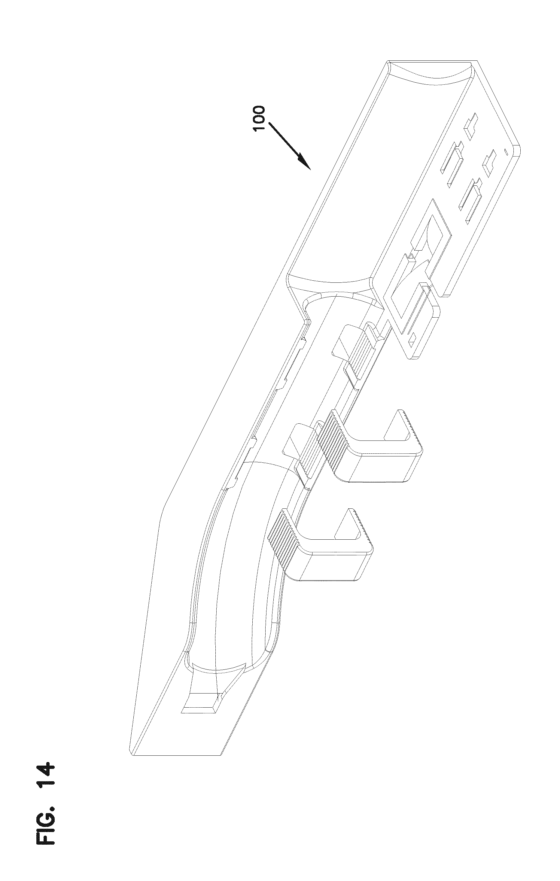
[0011] The cable mounts for the distribution cables or feeder cables can be snap mounted to the elements and/or mounted in a longitudinal slide mount, and include strength member clamps and cable clamps.
[0012] Groupings of loose cables can be managed with cable wraps or other cable guides such as flexible troughs.
[0013] The elements can be configured as desired and form building blocks for an optical fiber distribution system (ODF).
[0014] When the elements are mounted in a column in a rack, the cables can be placed in vertical cable guides to enter and exit the selected element.
[0015] The example rack is front accessible, however, the elements can be used in other racks, frames, cabinets or boxes including in arrangements where rear access is desirable or useful.
BRIEF DESCRIPTION OF THE FIGURES
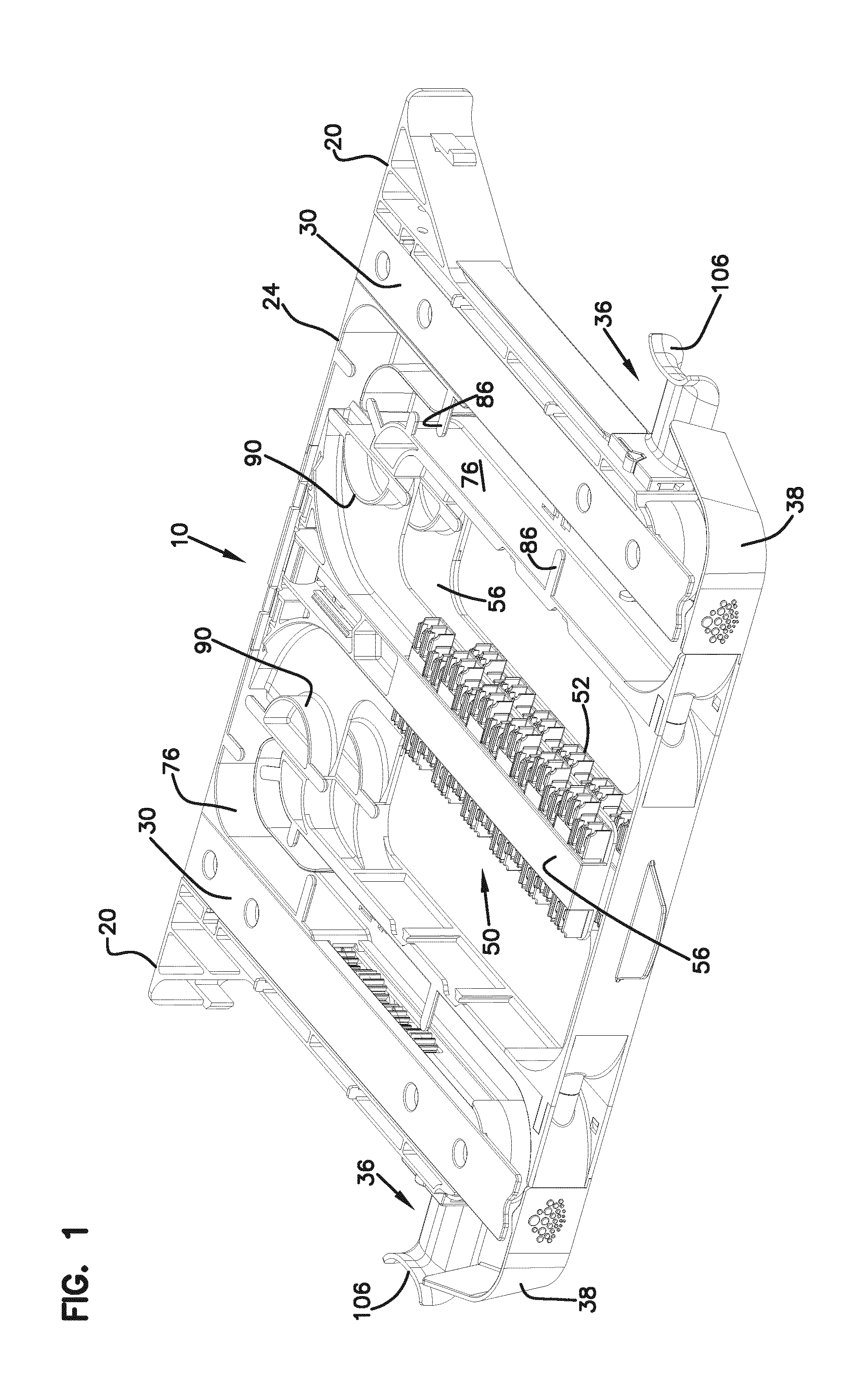
[0016] FIG. 1 is a perspective view of a first embodiment of an optical fiber distribution element in accordance of aspects of the present disclosure;
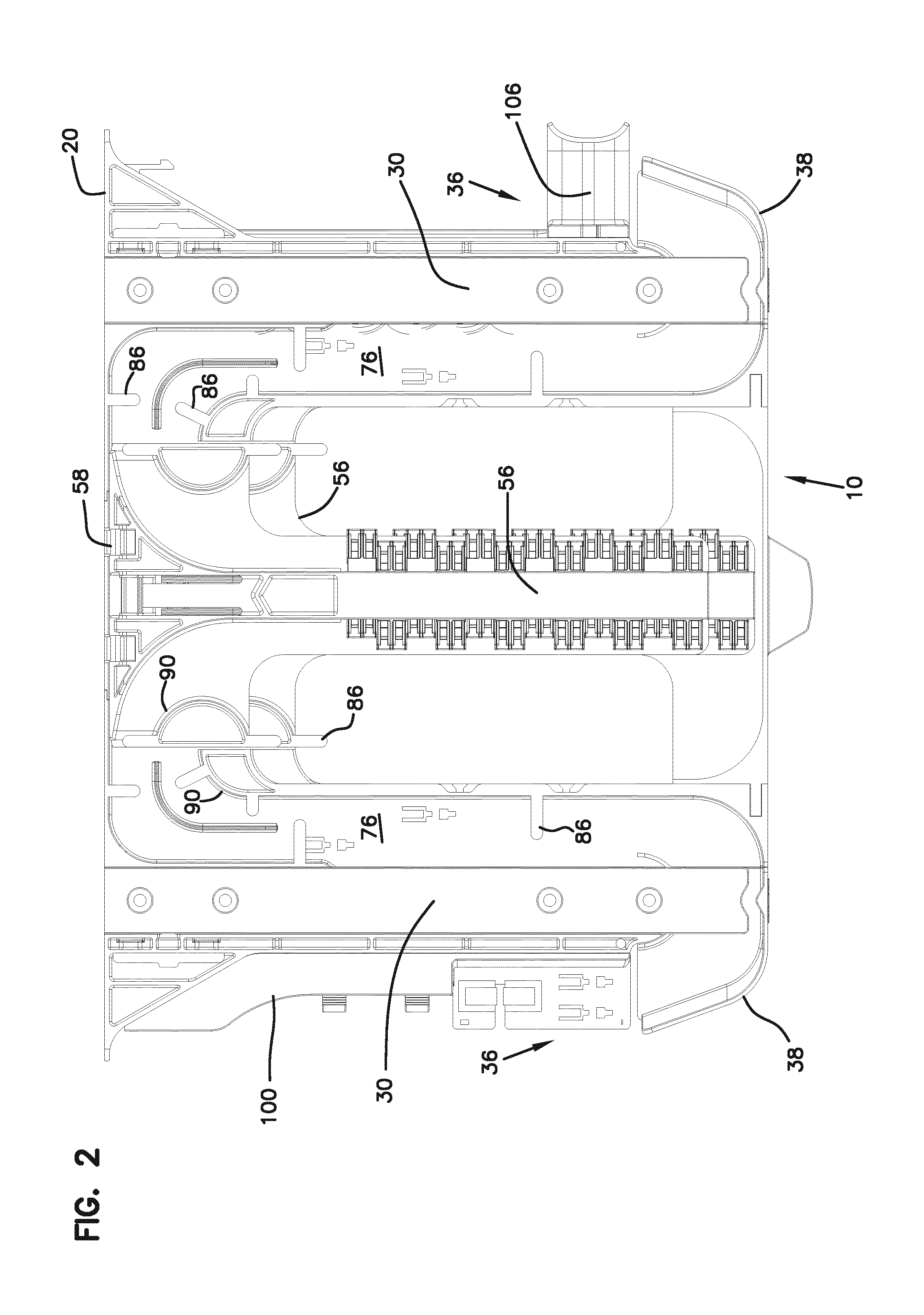
[0017] FIG. 2 is a top view of the element of FIG. 1;
[0018] FIG. 3 is a perspective view of the element of FIG. 1 showing the tray pulled forward from the chassis;
[0019] FIG. 4 shows one of the tray frame members pivoted upwardly from the tray;
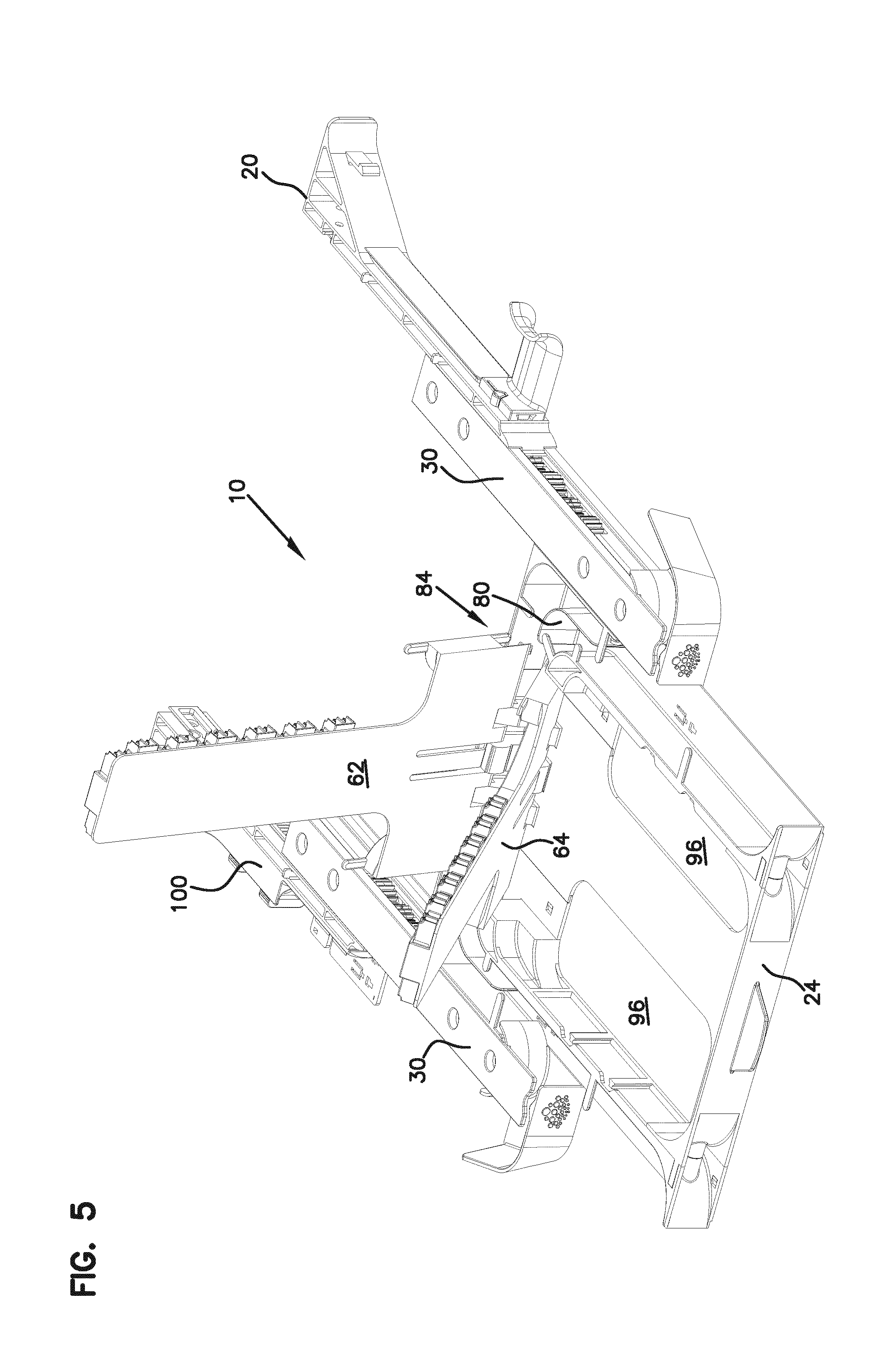
[0020] FIG. 5 shows a second frame member pivoted upwardly relative to the tray;
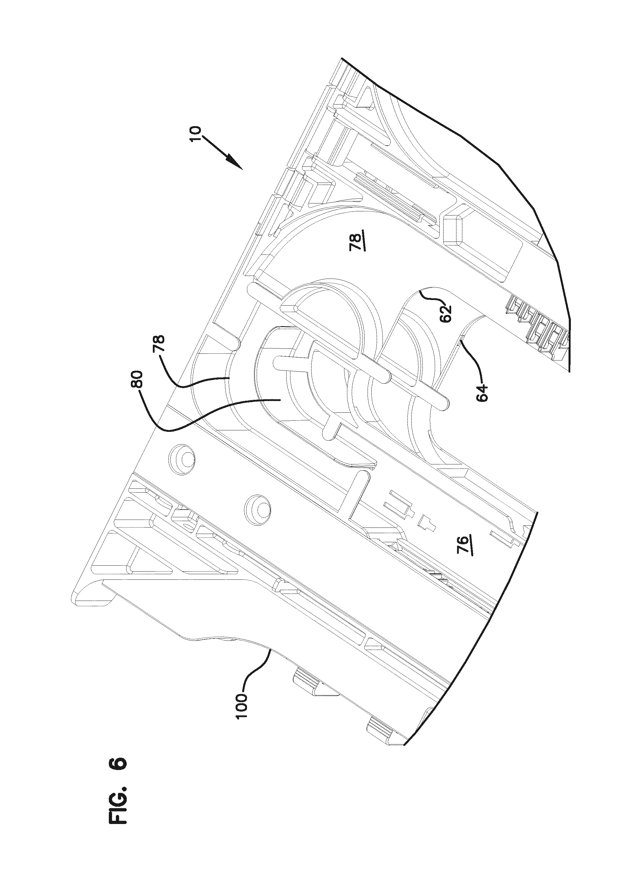
[0021] FIG. 6 shows a portion of a cable management area of the element of FIG. 1;
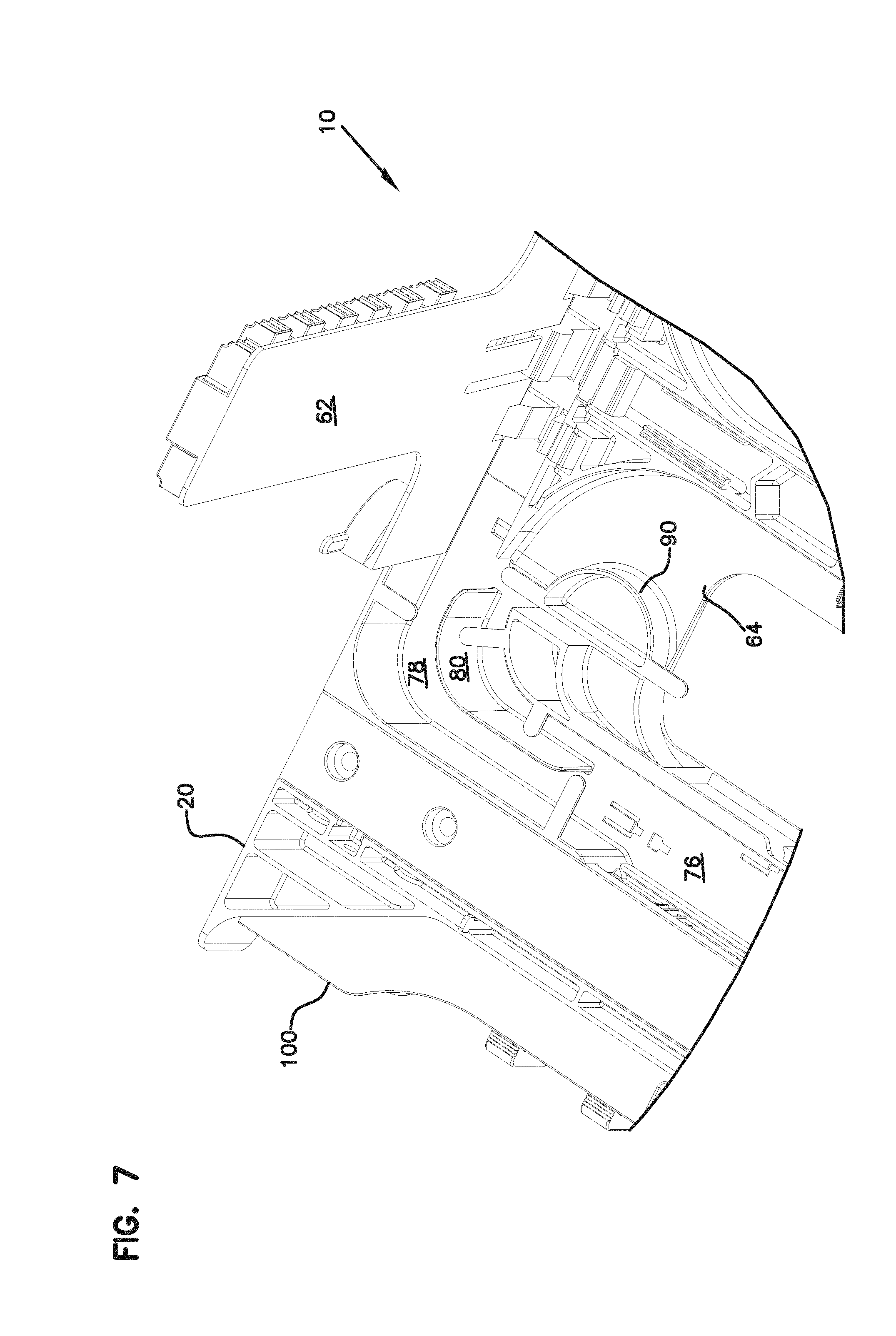
[0022] FIG. 7 shows a similar view to FIG. 6, with one of the frame members pivoted upwardly;
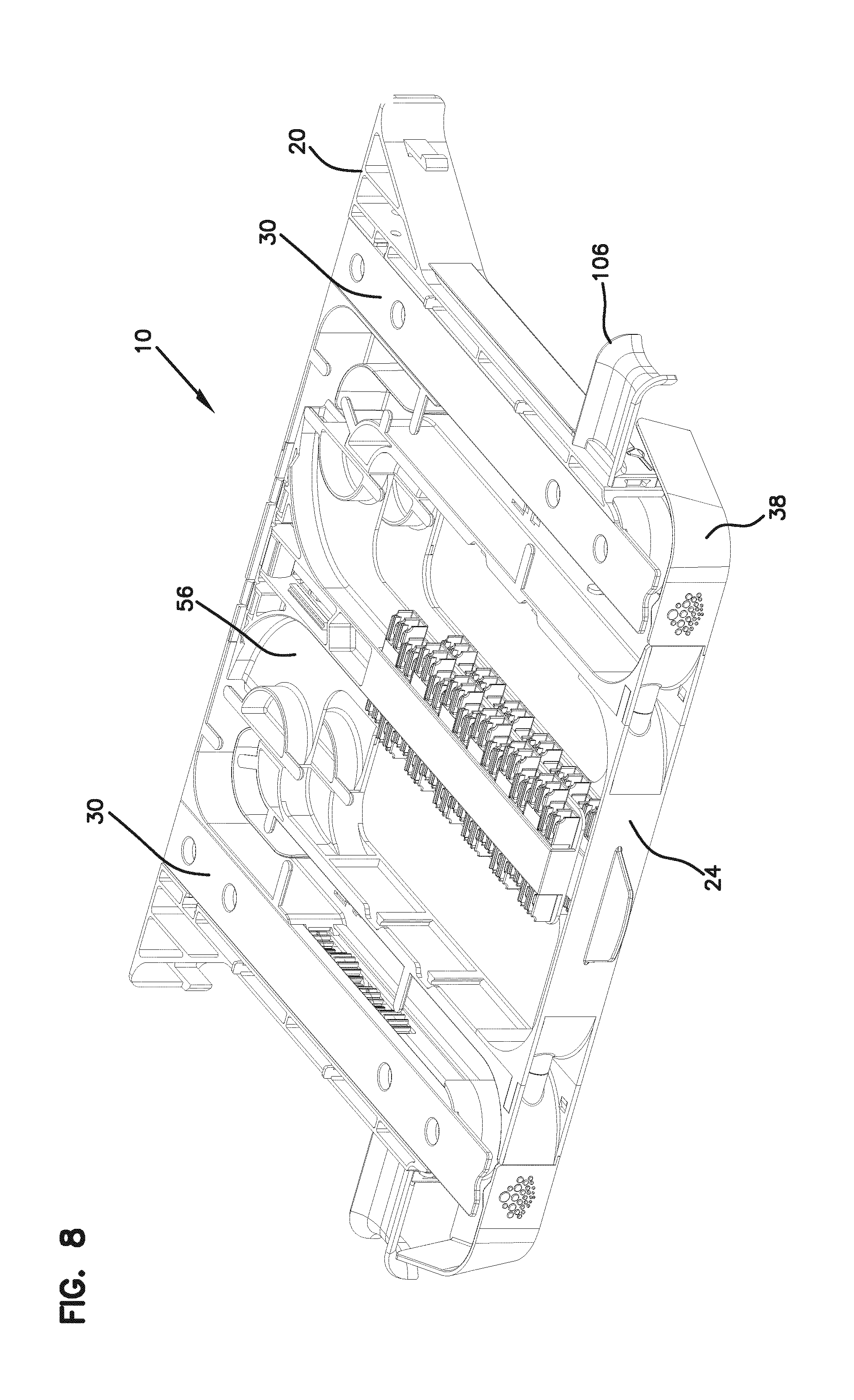
[0023] FIG. 8 shows an alternative embodiment of an element with different cable management at the entry points;
[0024] FIG. 9 shows three of the elements of FIG. 8 mounted in a block formation, with cable radius limiters at the entry point mounted in an alternative position;
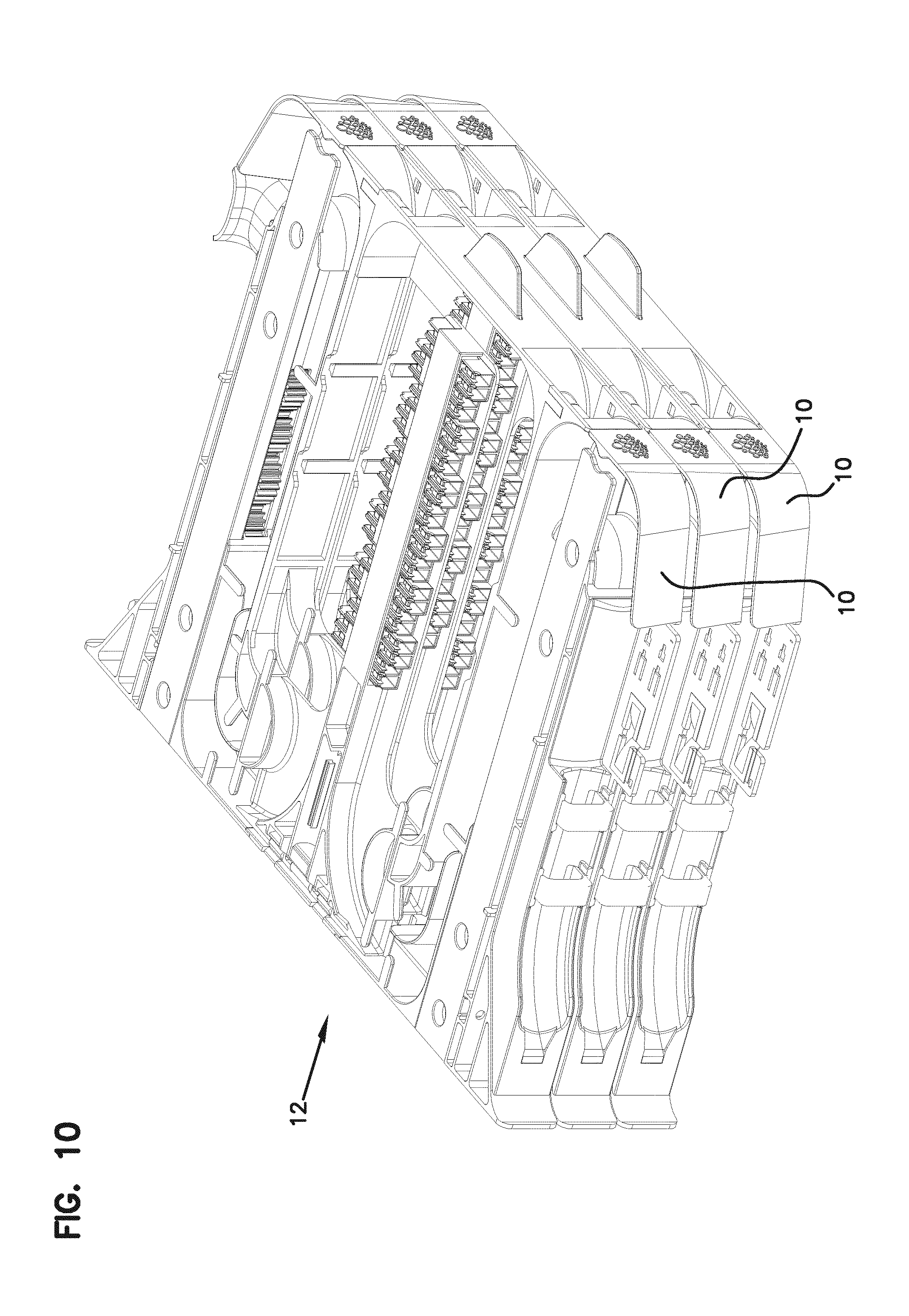
[0025] FIG. 10 is a perspective view of the block of FIG. 9;
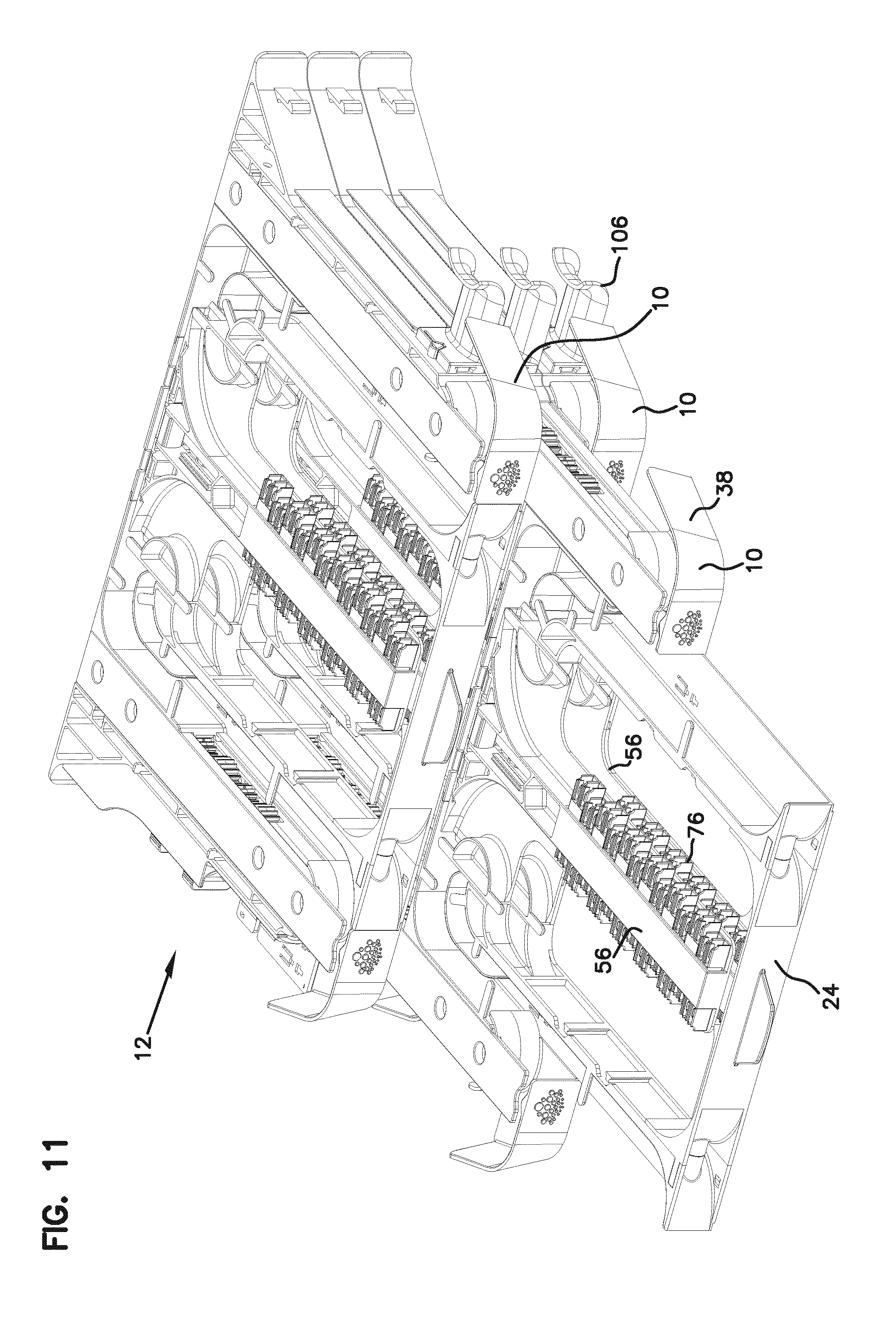
[0026] FIG. 11 is a view of the block of FIG. 9, with the tray of the middle element pulled forward for access to the fiber terminations;
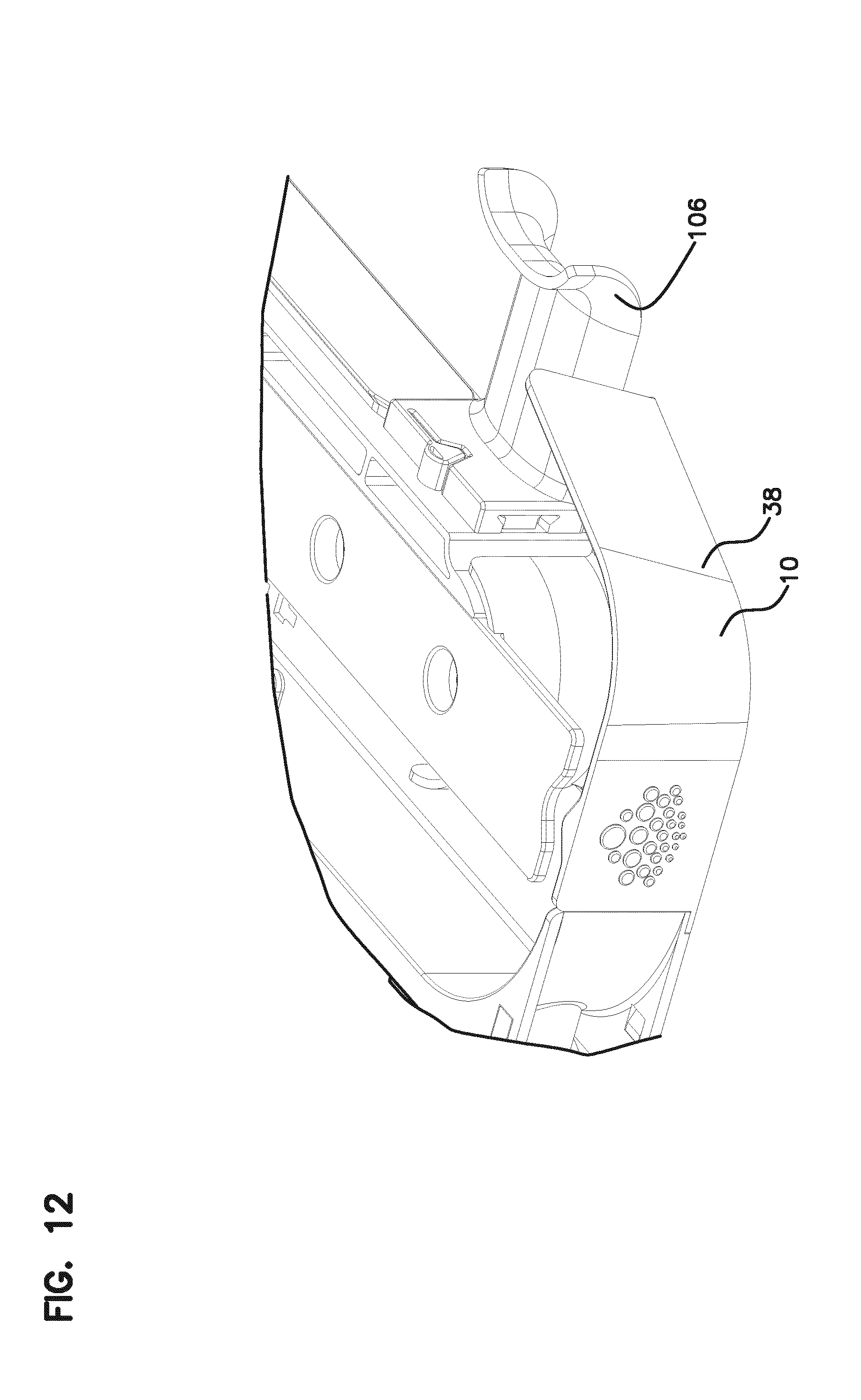
[0027] FIG. 12 shows an enlarged portion of an entry point for one of the elements with a cable radius limiter in a first position;
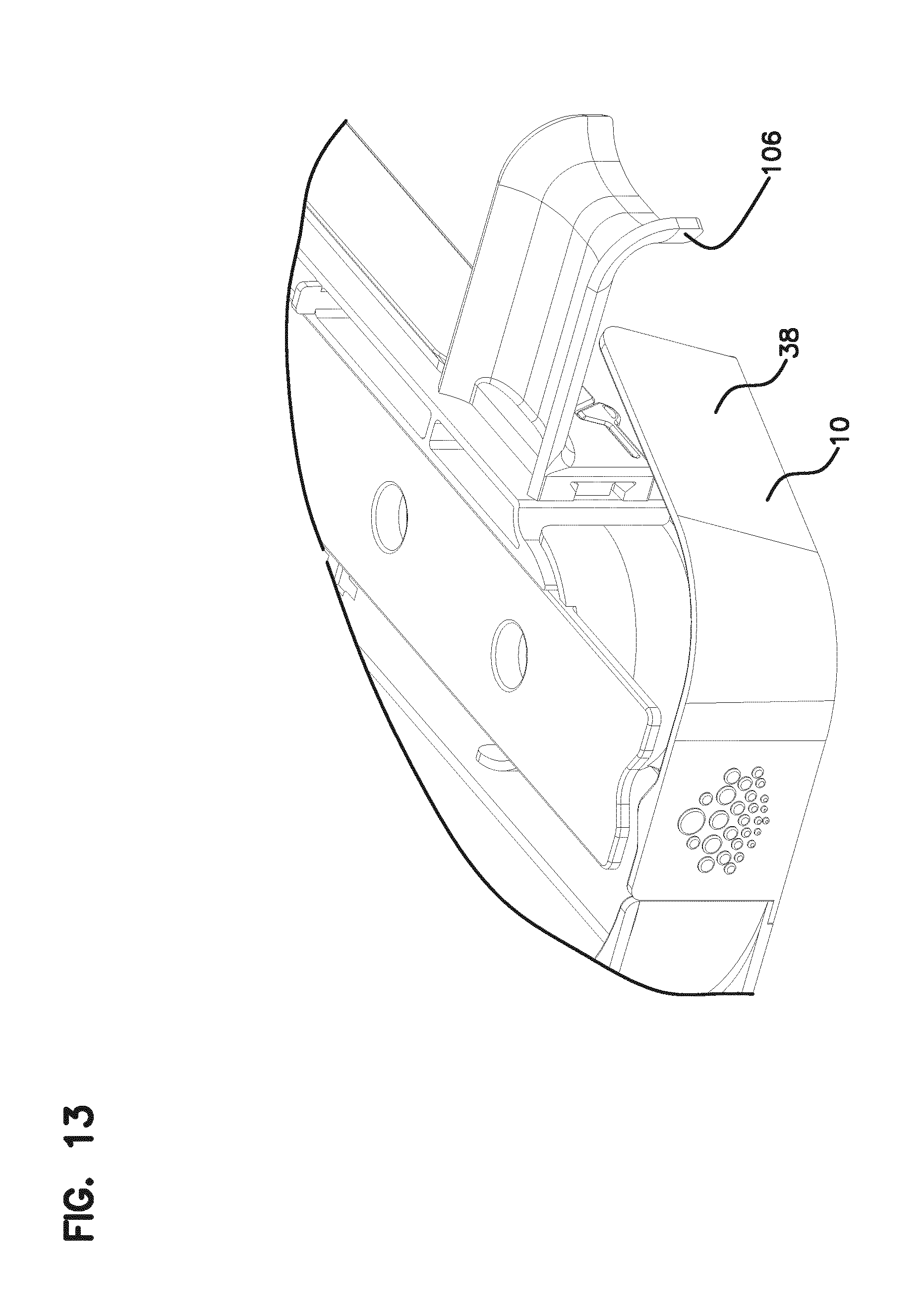
[0028] FIG. 13 shows a similar view as in FIG. 12, with the cable radius limiter positioned in an alternate position;
[0029] FIG. 14 shows an exploded view of a cable mount;
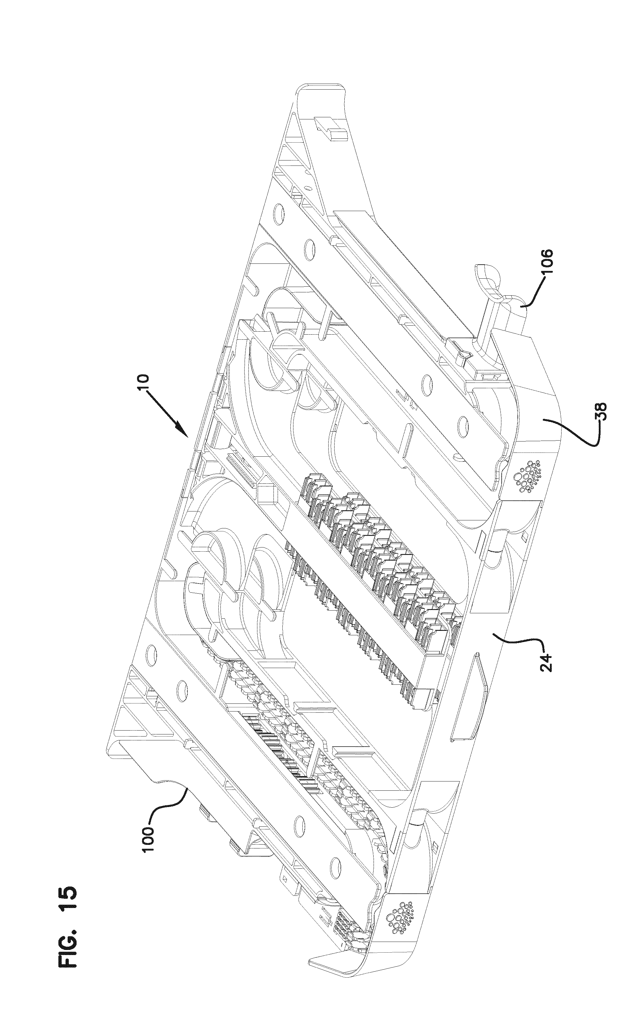
[0030] FIG. 15 shows an element with a cable mount on one side, and a cable radius limiter on an opposite side;
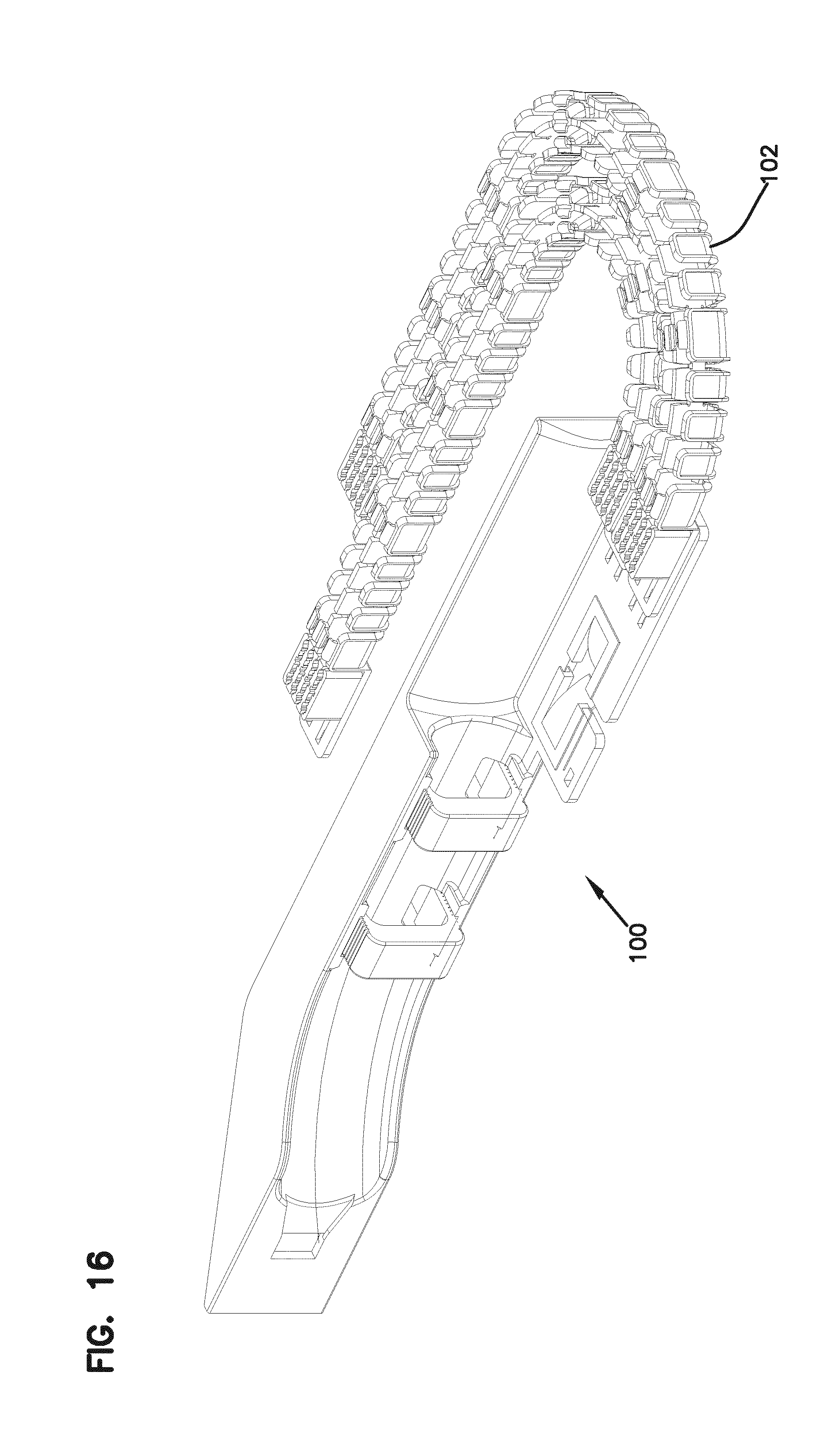
[0031] FIG. 16 shows an alternative cable mount;
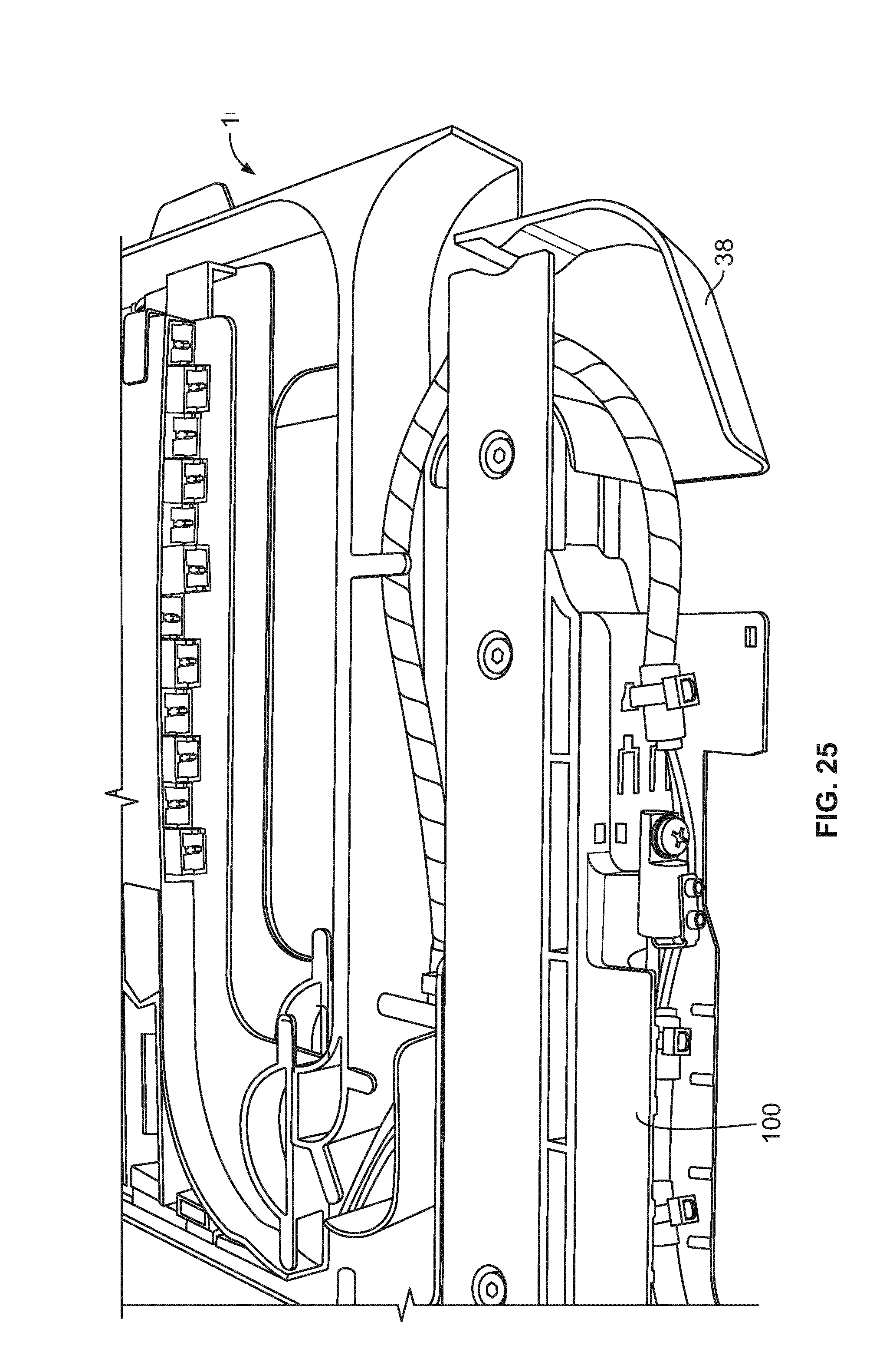
[0032] FIGS. 17-29 show various views of the elements shown in FIGS. 1-16 including additional details and cable routings shown for illustration purposes;
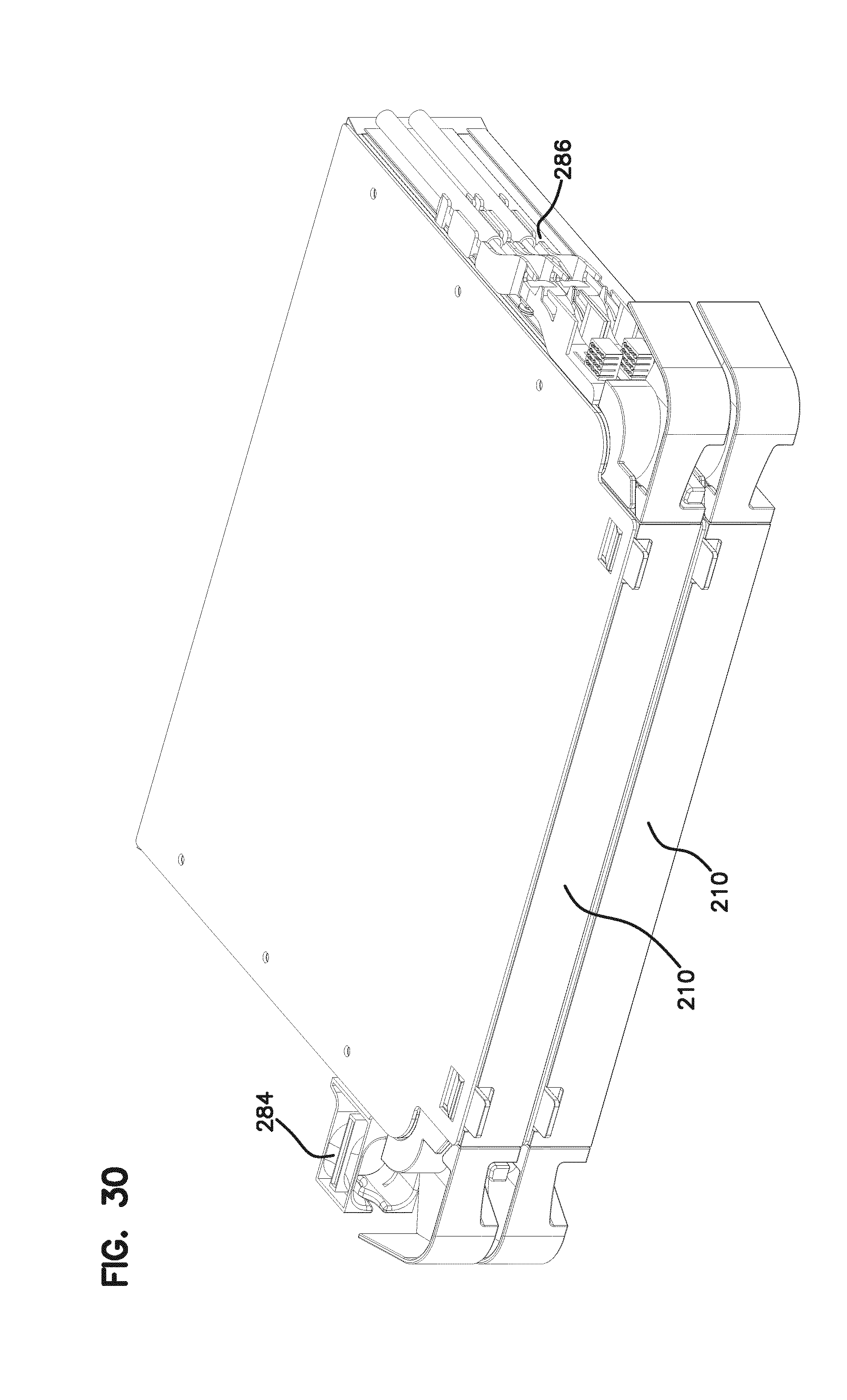
[0033] FIG. 30 shows an alternative embodiment of a block of two alternative elements;
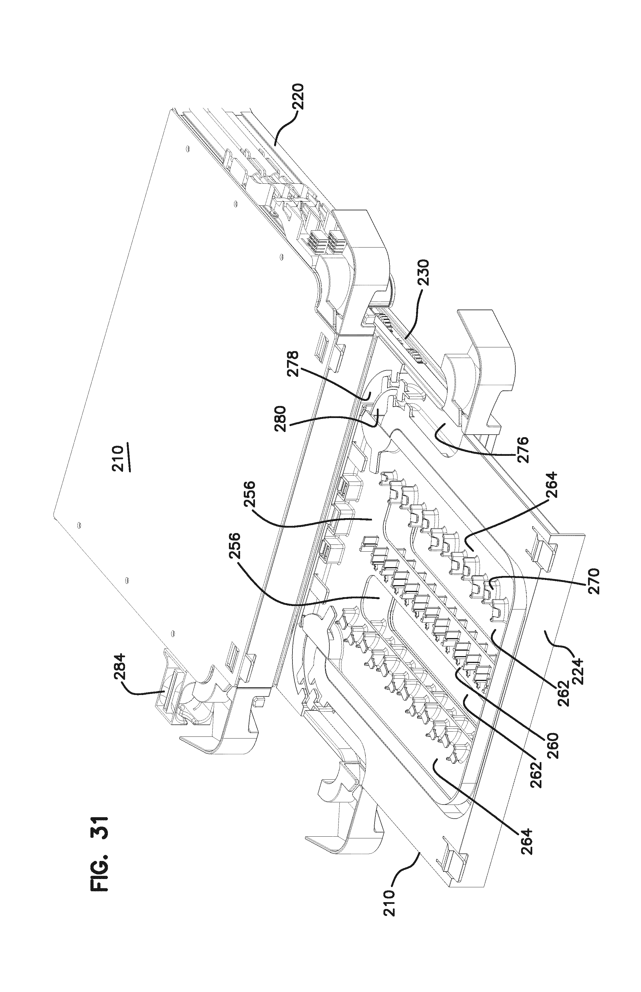
[0034] FIG. 31 shows a tray pulled forward from the chassis of one of the elements of the block of FIG. 30;
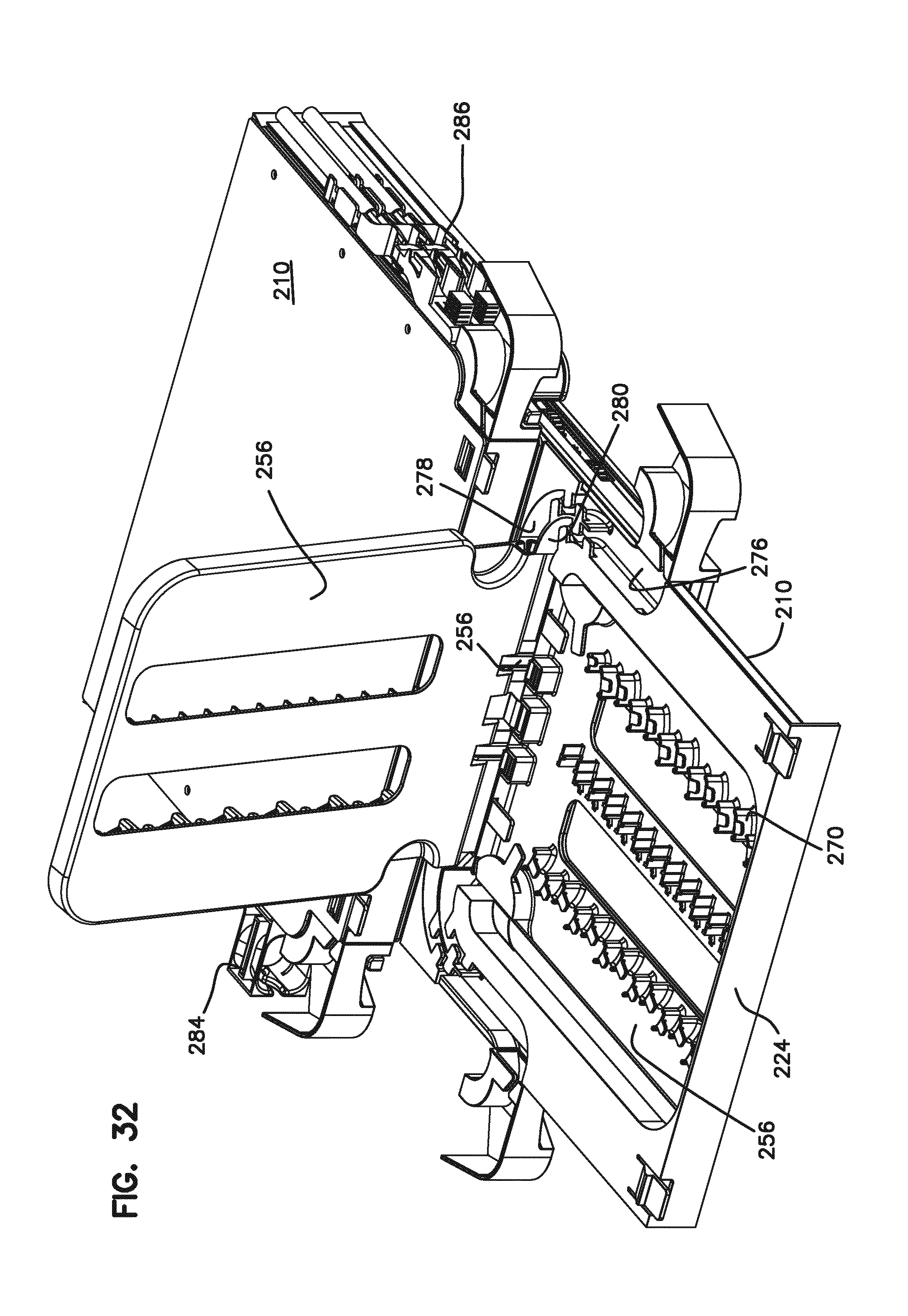
[0035] FIG. 32 shows the tray extended forward as in the view of FIG. 31, with one of the frame members pivoted upwardly;
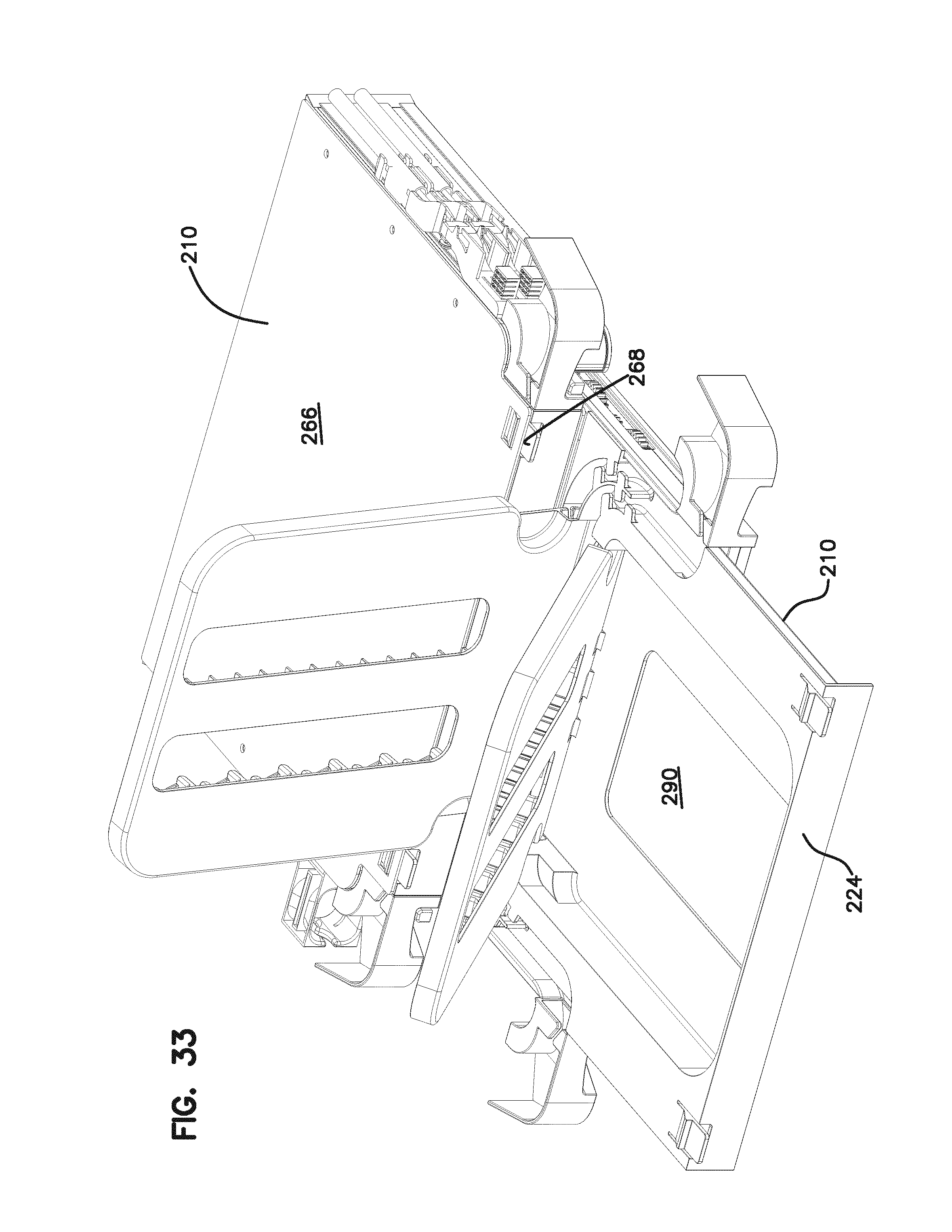
[0036] FIG. 33 is a view similar to the view of FIG. 32, with a second frame member pivoted upwardly;
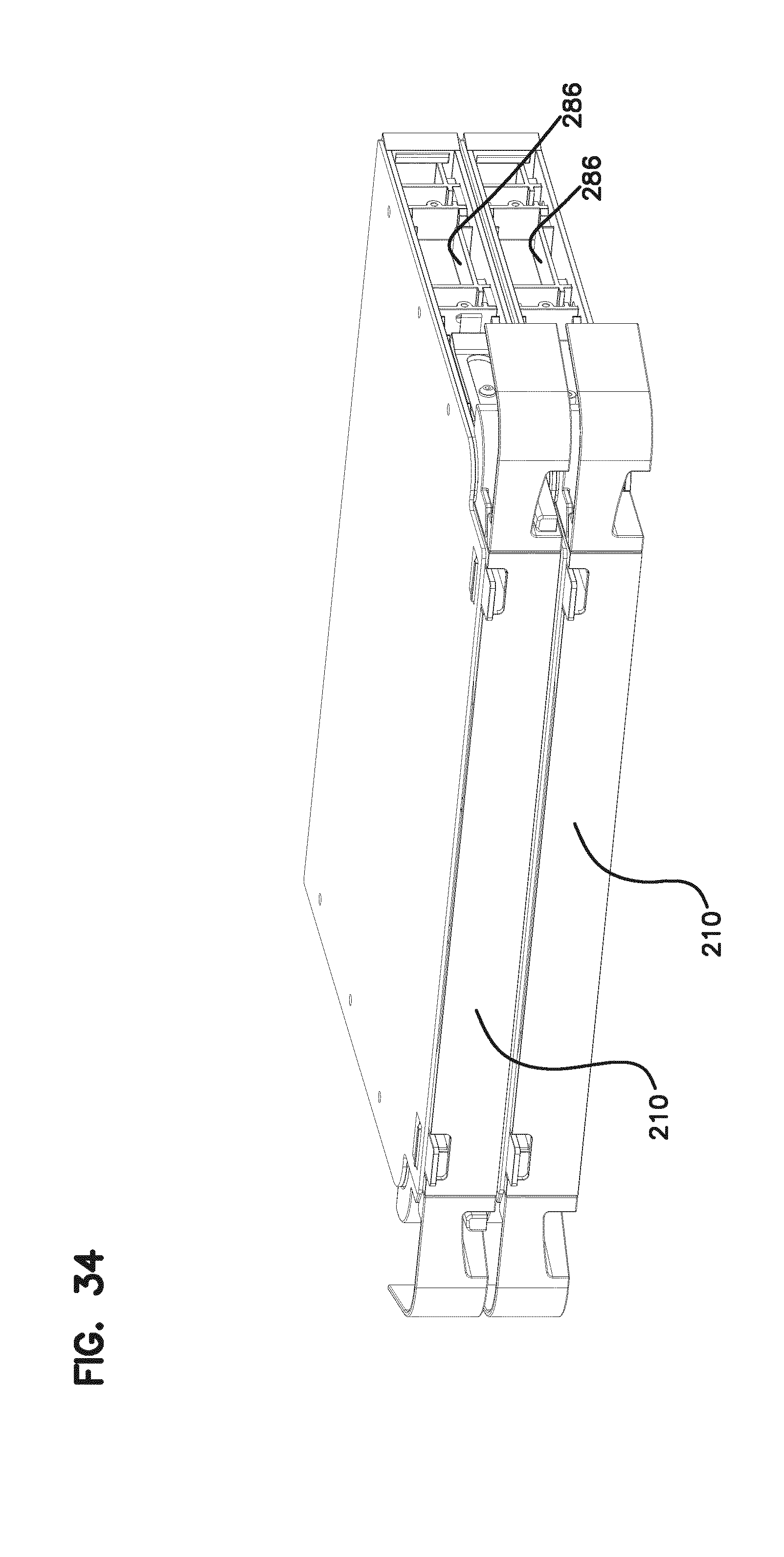
[0037] FIG. 34 shows a block including two elements;
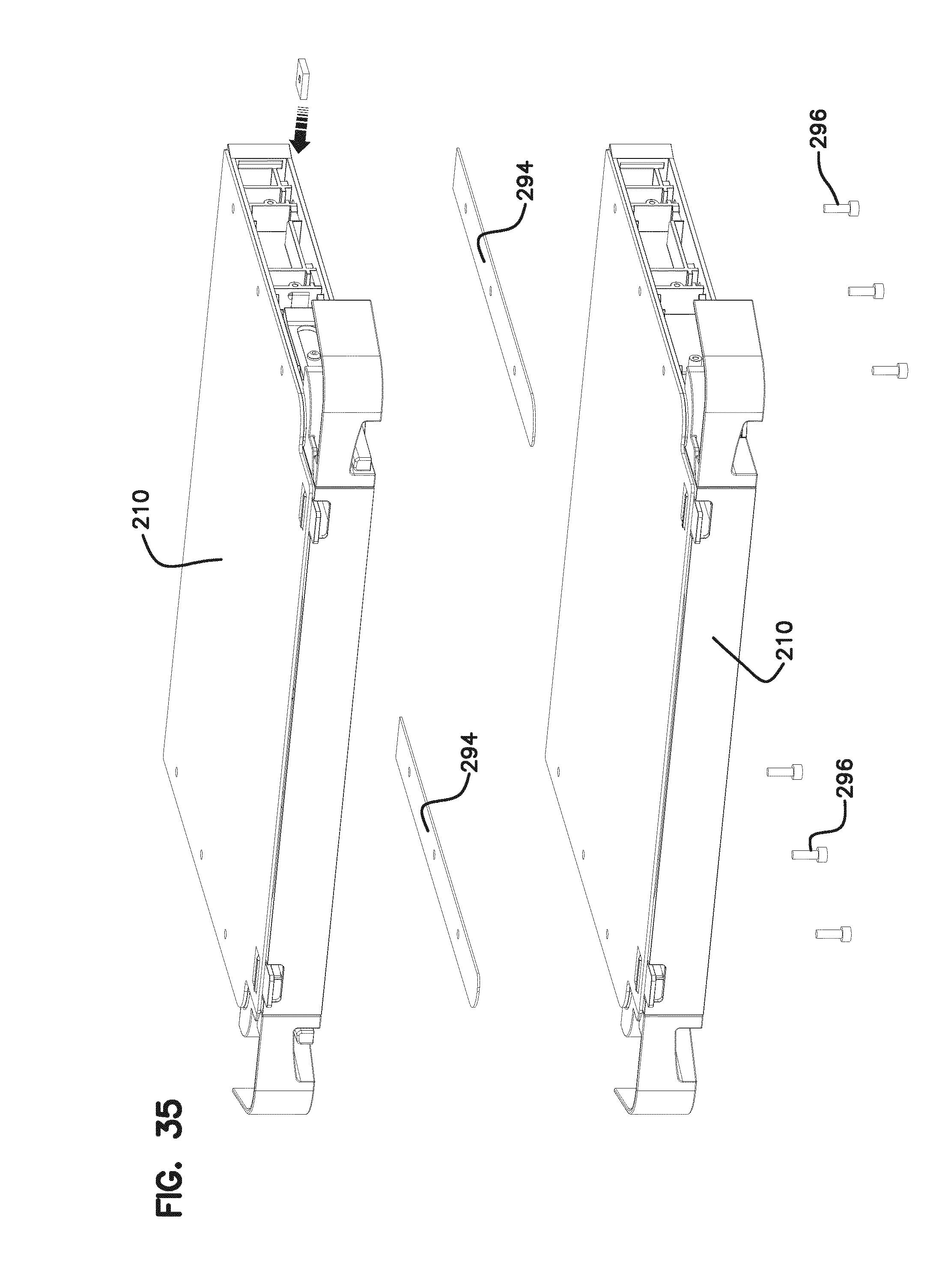
[0038] FIG. 35 shows an exploded view of the two elements of the block of FIG. 34;
[0039] FIG. 36 shows a single element;
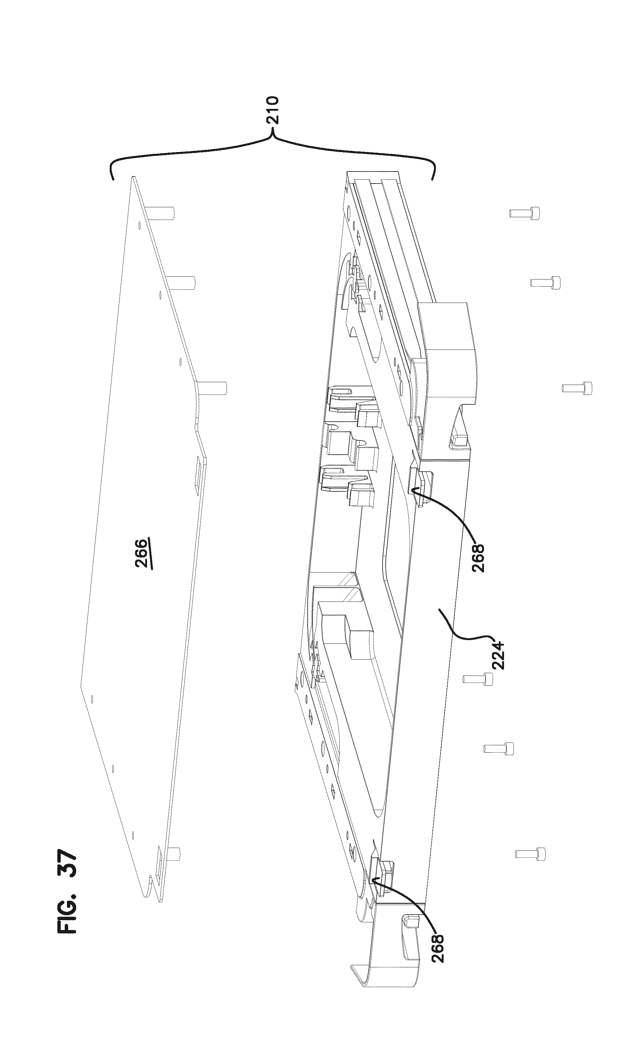
[0040] FIG. 37 shows an exploded view of the element of FIG. 36;
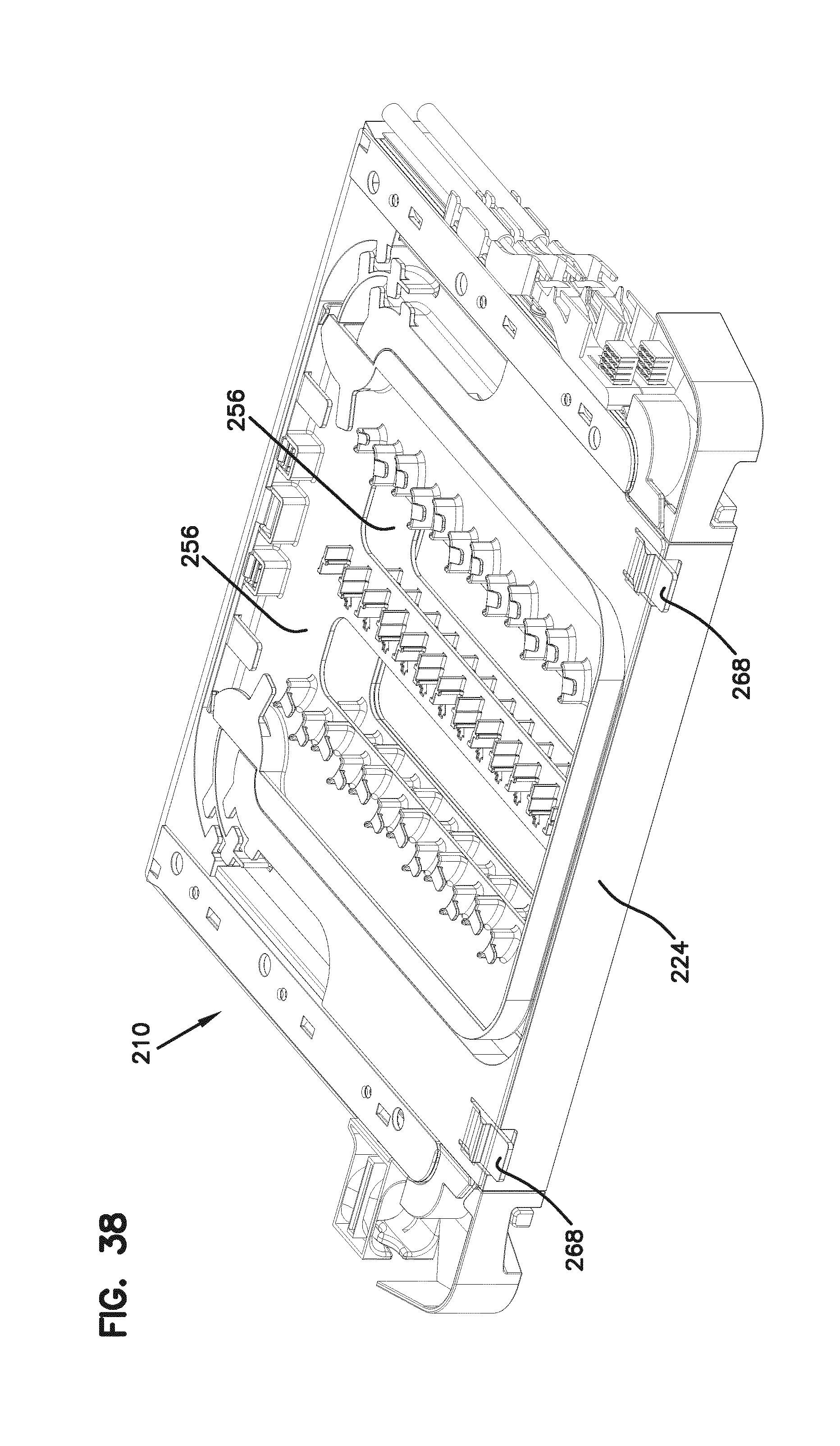
[0041] FIG. 38 shows the element of FIG. 37, without the top cover;
[0042] FIG. 39 is a top view of the element of FIG. 38;
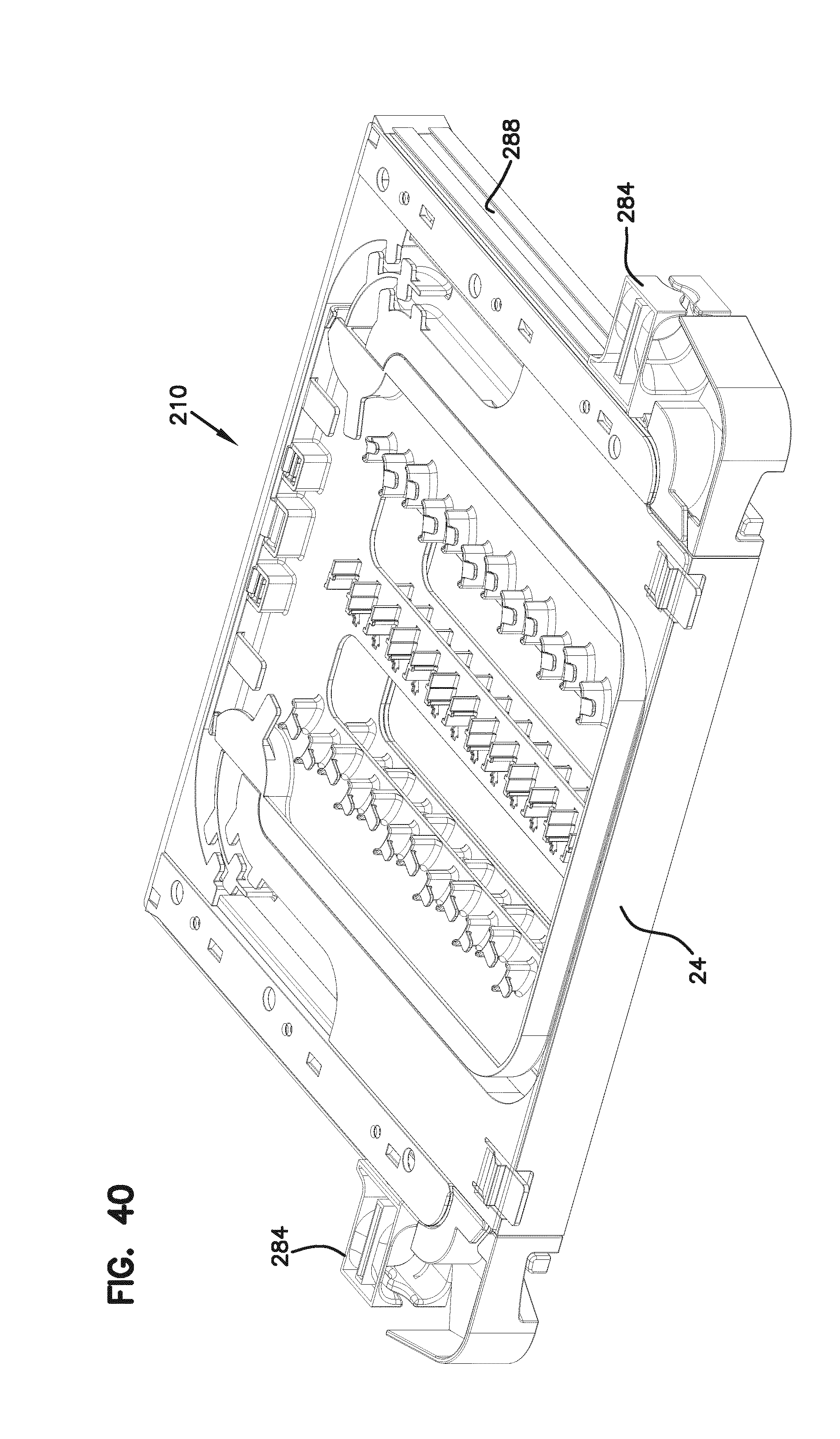
[0043] FIG. 40 is an alternative view of the element of FIG. 38, showing alternative devices at the cable entry points;
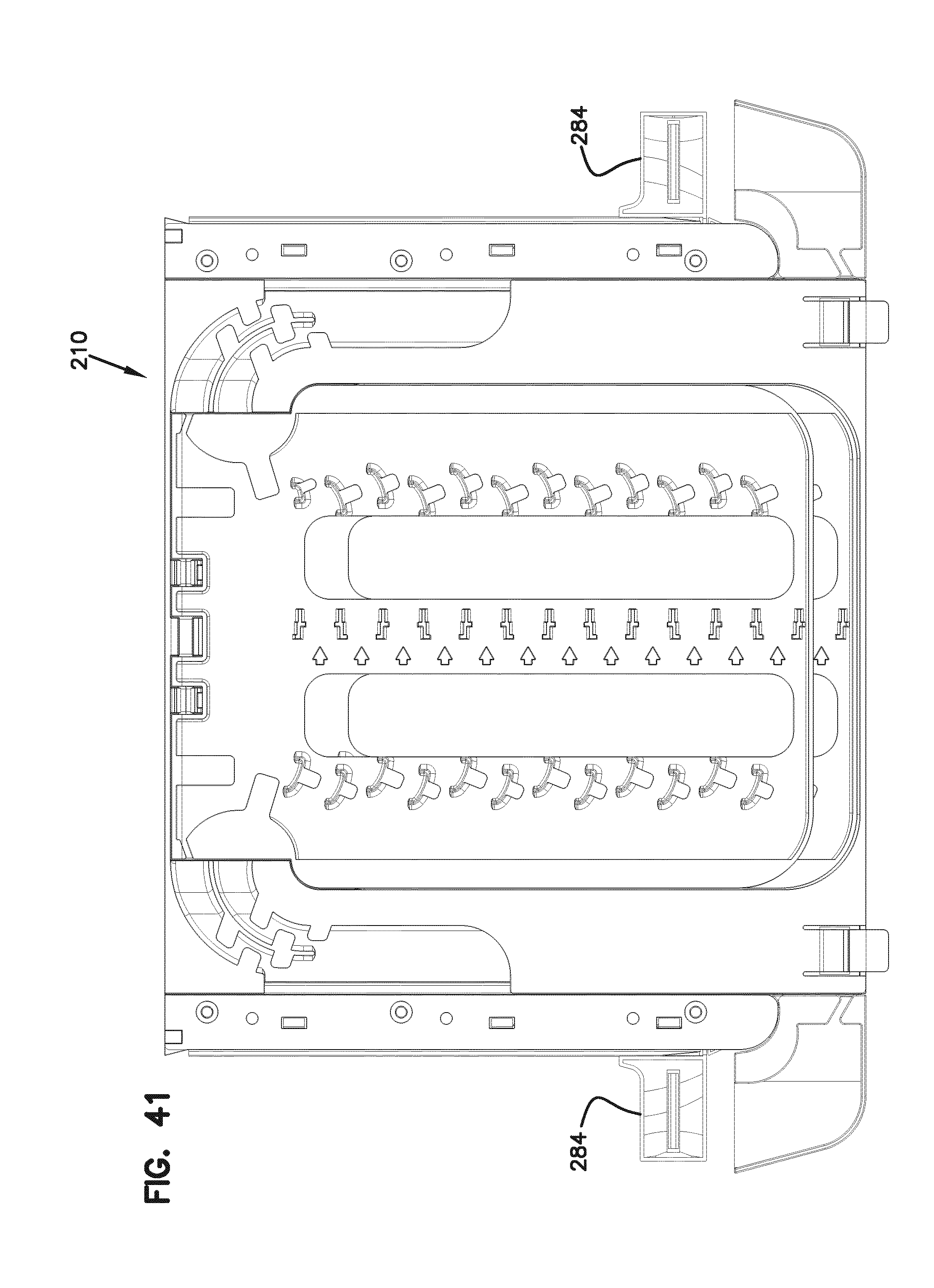
[0044] FIG. 41 is a top view of the element of FIG. 40;
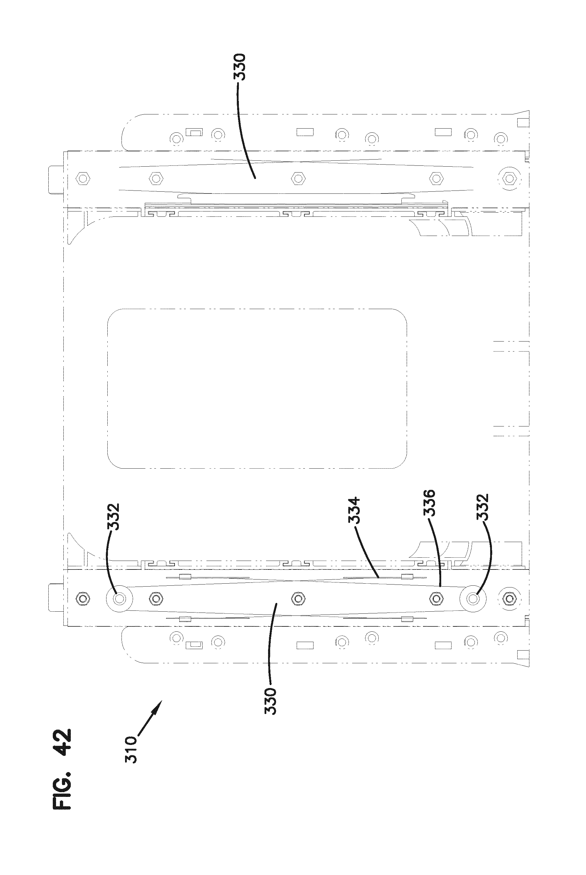
[0045] FIG. 42 shows an alternative embodiment of an element in a top view with an alternative synchronized movement feature;
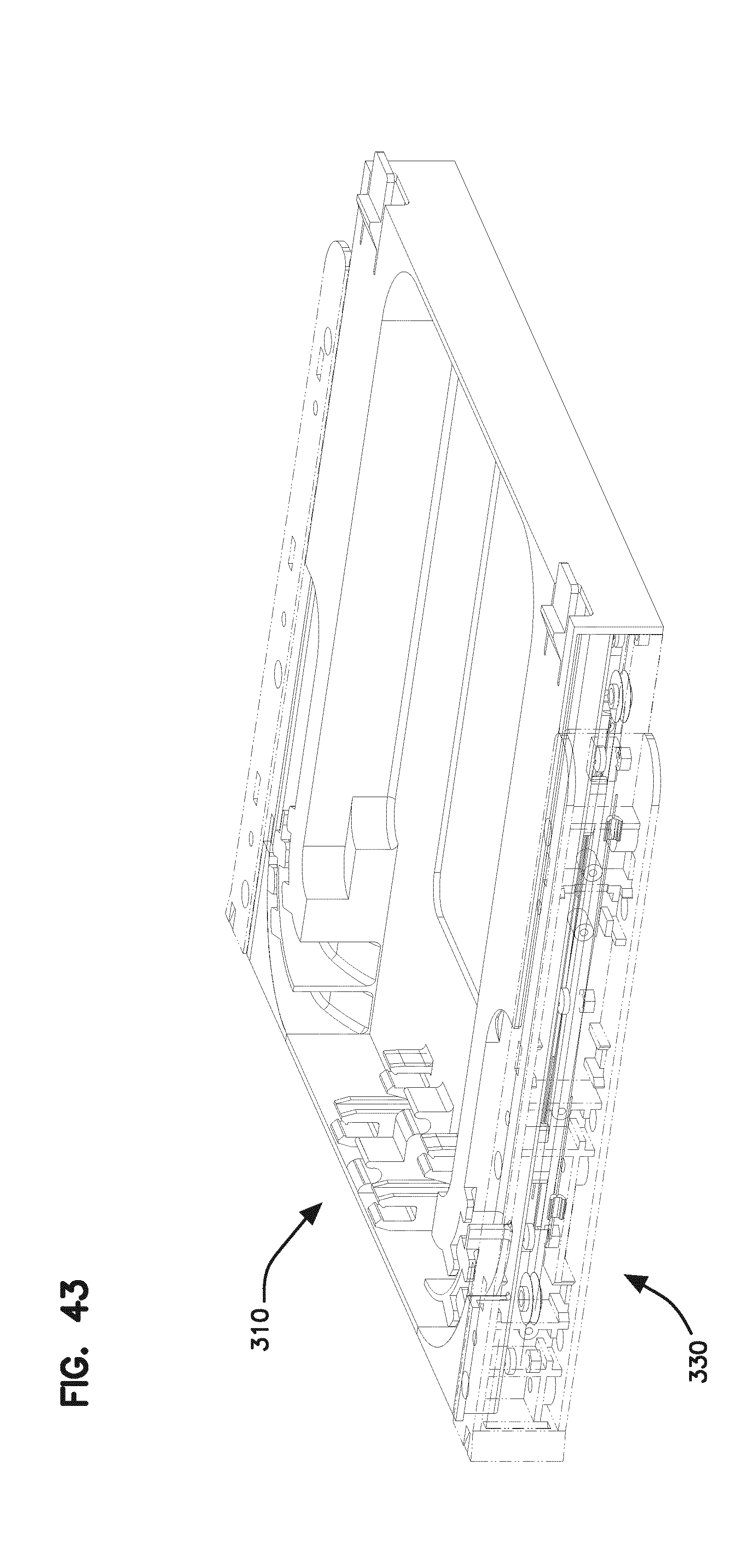
[0046] FIG. 43 is a perspective view of the element of FIG. 42;
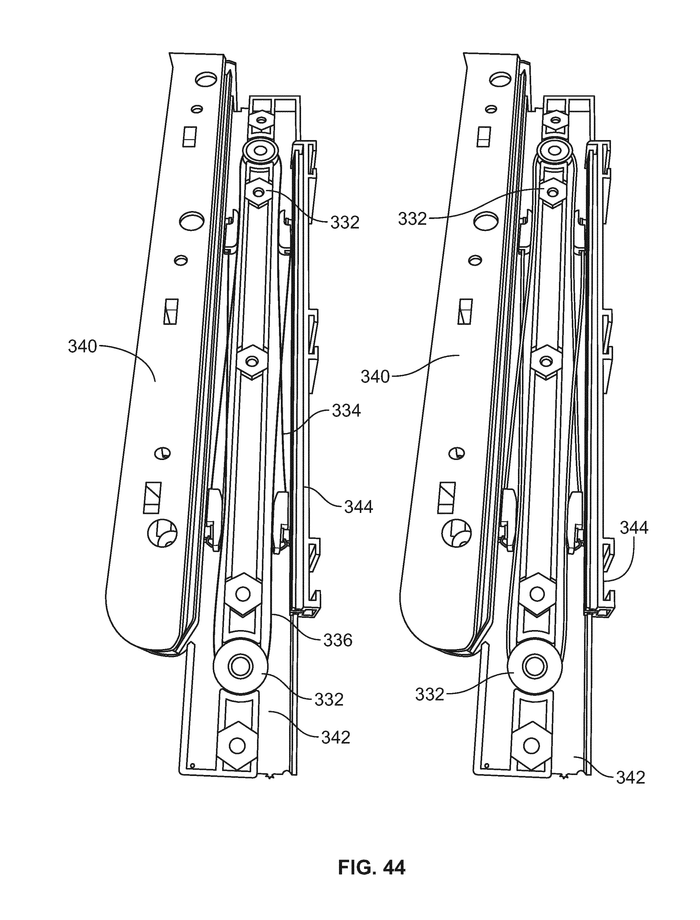
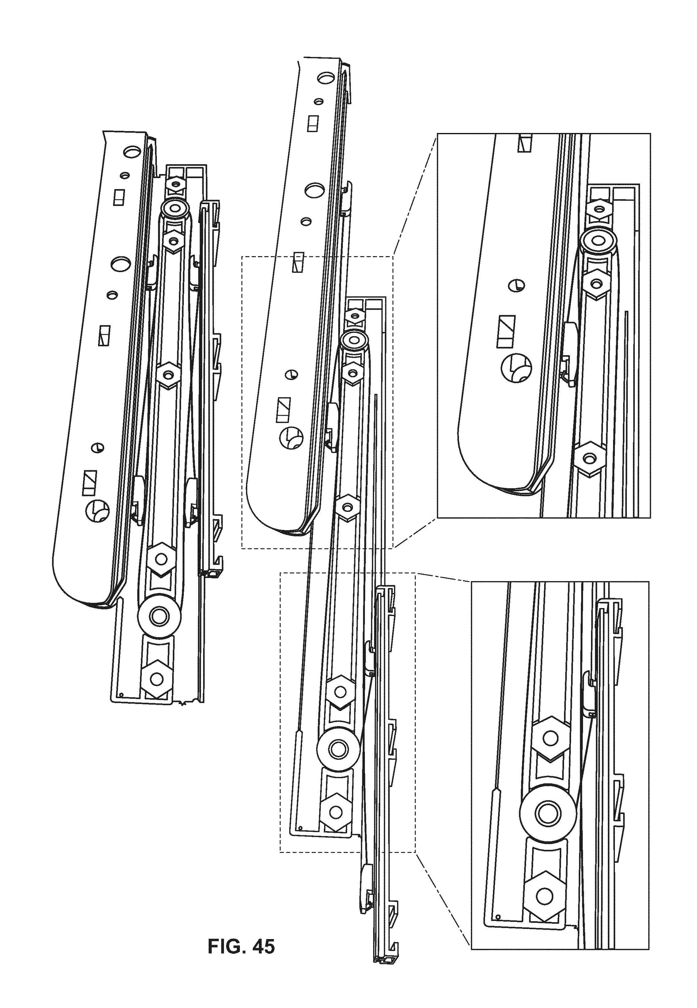
[0047] FIGS. 44 and 45 show movement of the various components of the synchronized movement feature of FIGS. 42 and 43;
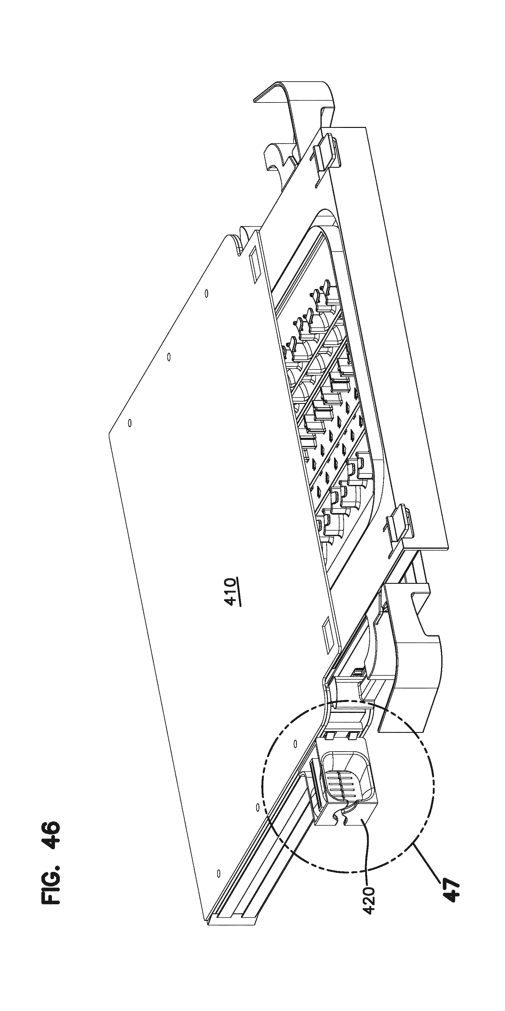
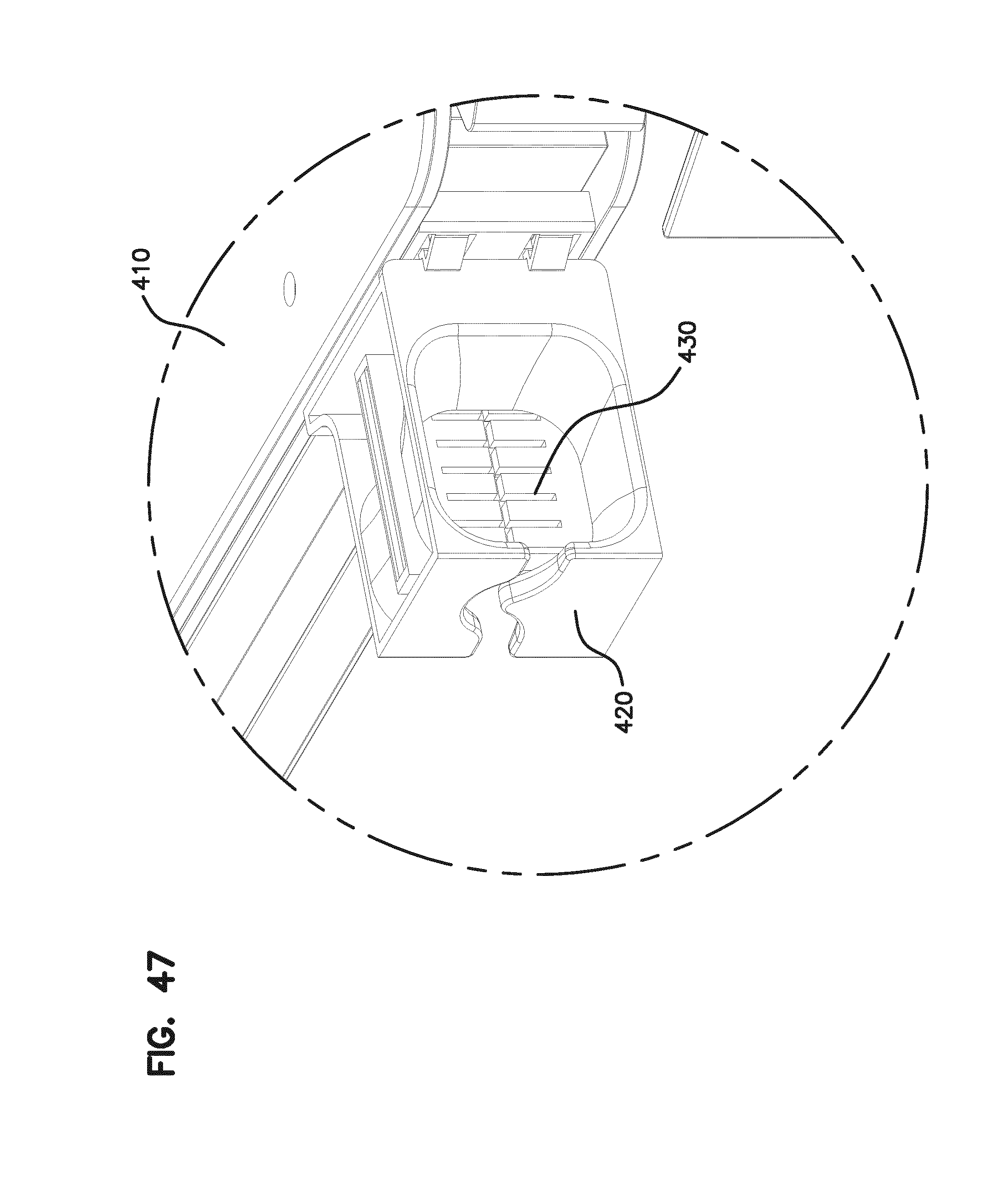
[0048] FIGS. 46 and 47 show an element with an alternative radius limiter at the cable entry and exit locations;
[0049] FIGS. 48 and 49 show an element with alternative radius limiters on the slide mechanism;
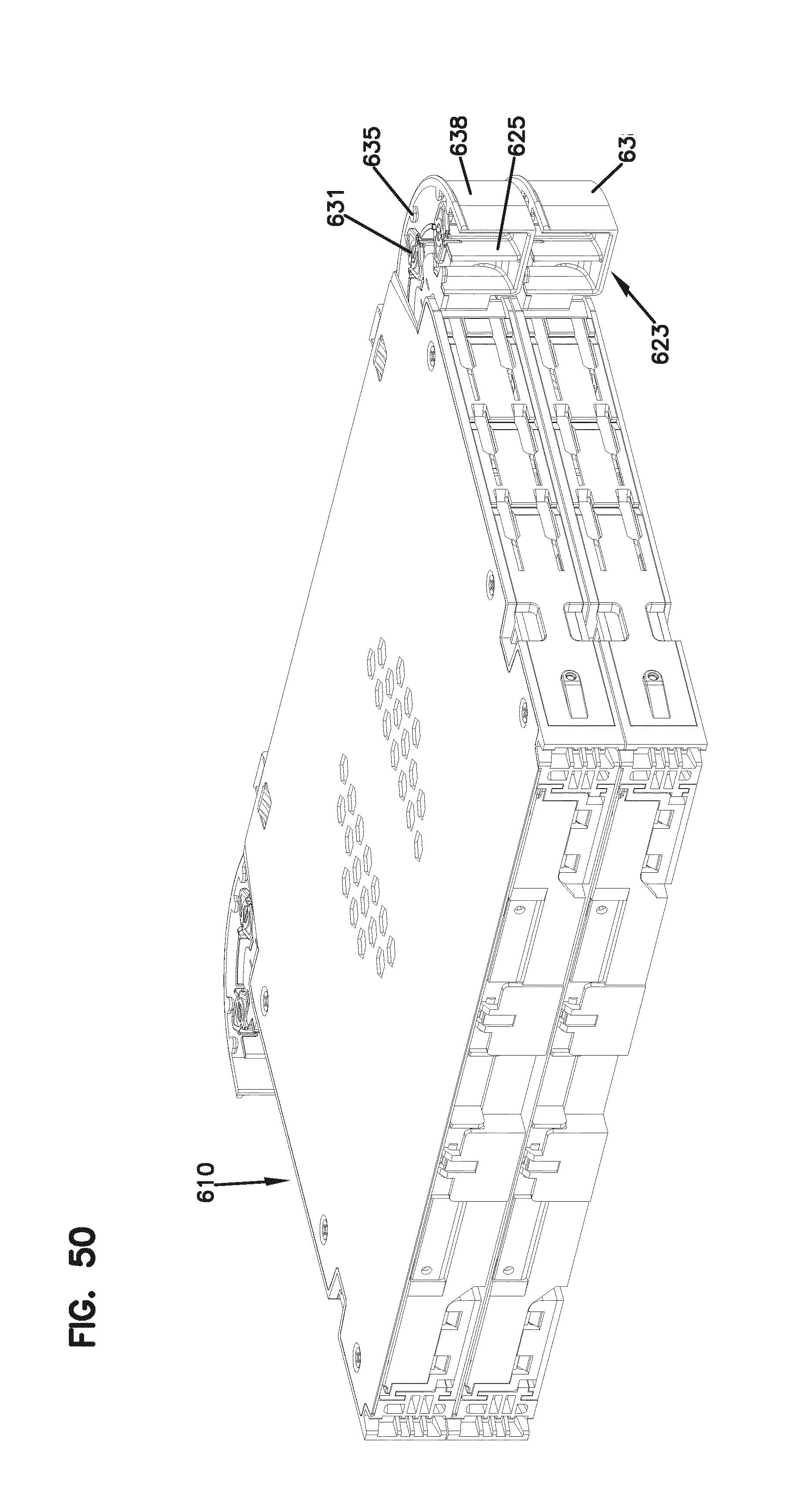
[0050] FIG. 50 shows a pair of elements in a stacked configuration, the elements shown with another alternative radius limiter on the slide mechanism; and
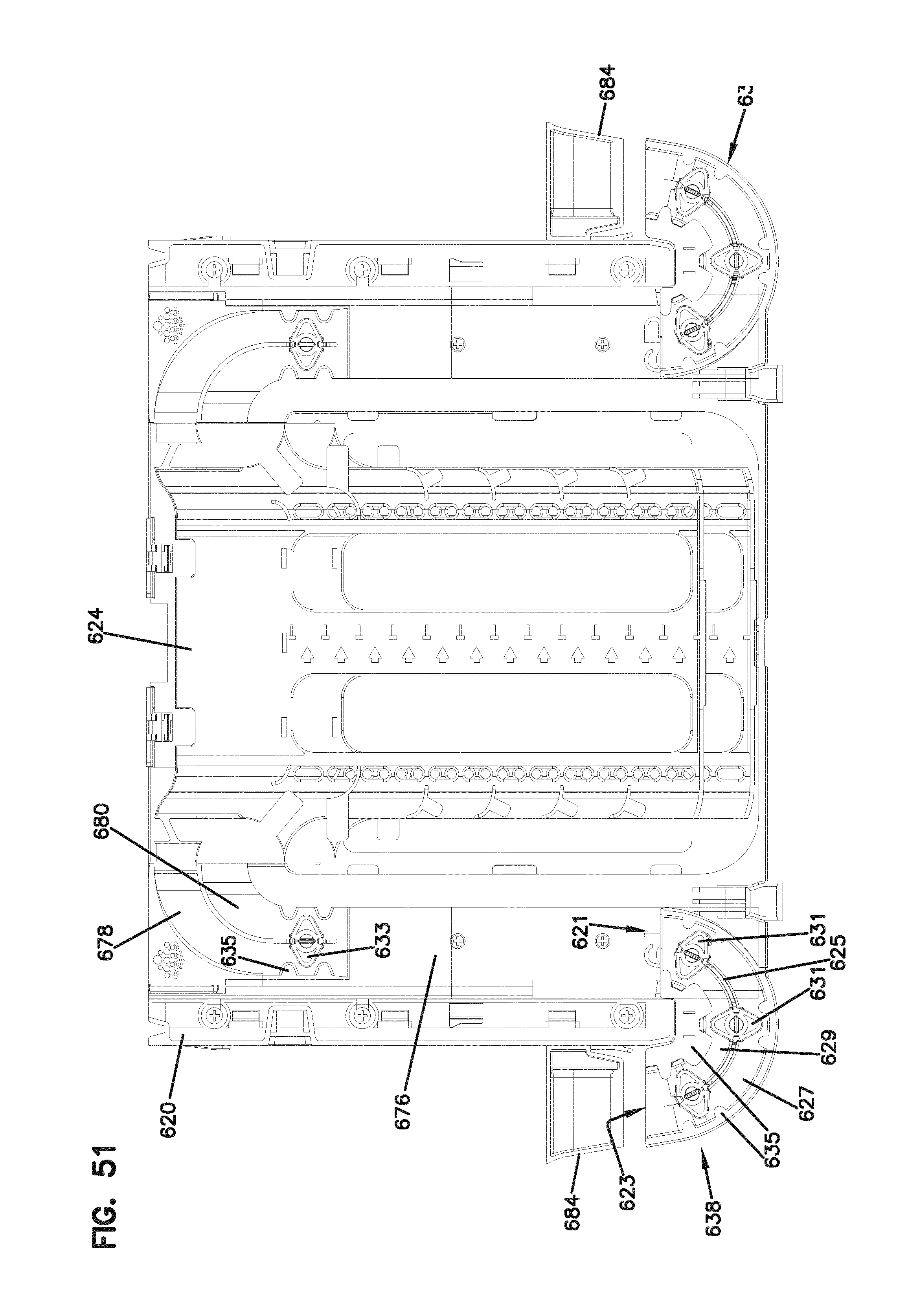
[0051] FIG. 51 is a top view of one of the elements of FIG. 50 illustrating the alternative radius limiter.
DETAILED DESCRIPTION
[0052] Referring now to FIGS. 1-16, various embodiments of an optical fiber distribution element 10, or element 10, are shown. The elements 10 can be individually mounted as desired to telecommunications equipment including racks, frames, or cabinets. The elements 10 can be mounted in groups or blocks 12 which forms a stacked arrangement. In one embodiment, a vertical stack of elements 10 populates an optical fiber distribution rack.
[0053] Each element 10 holds fiber terminations, or other fiber components including fiber splitters and/or fiber splices. In the case of fiber terminations, incoming cables are connected to outgoing cables through connectorized cable ends which are connected by adapters, as will be described below.
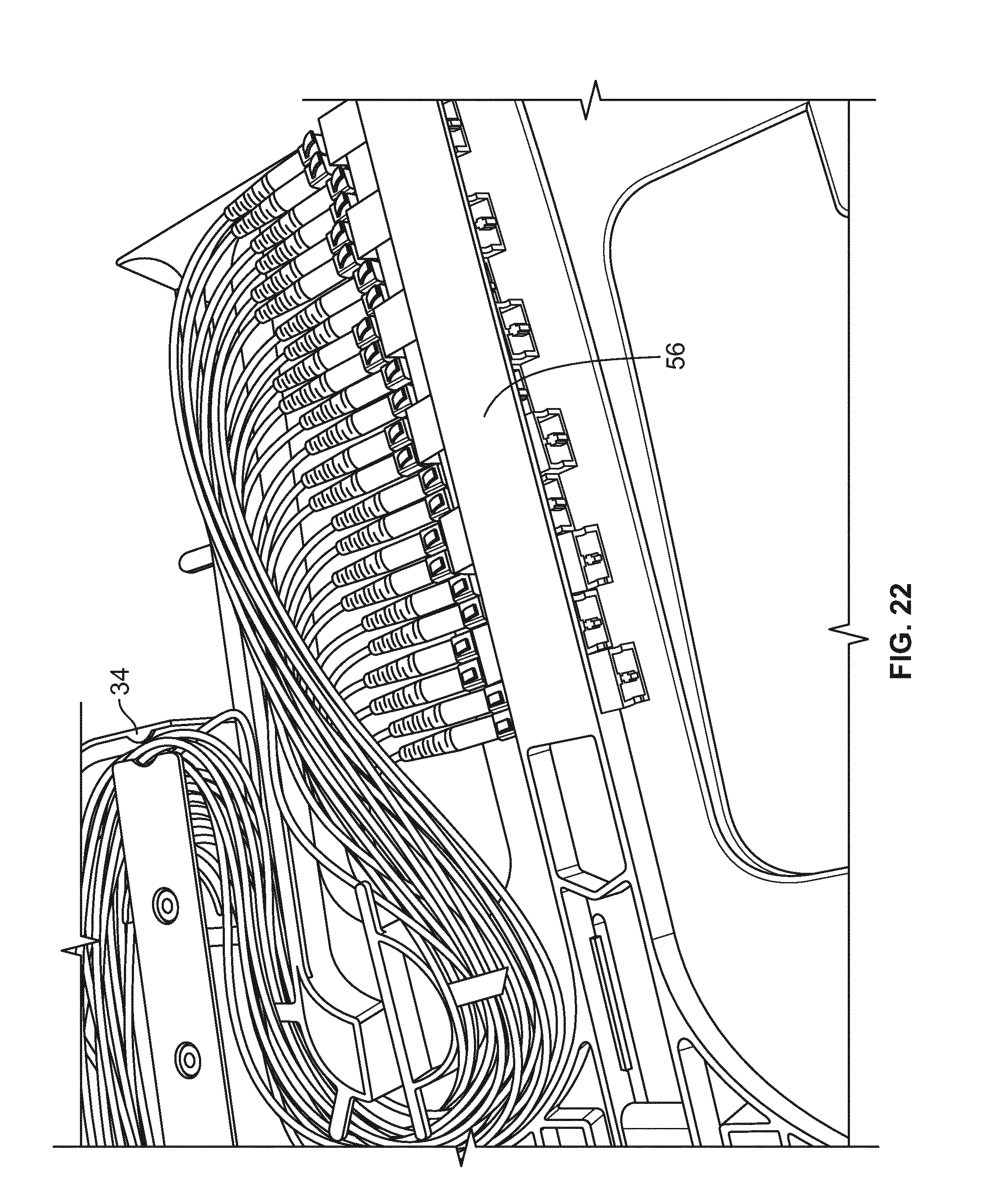
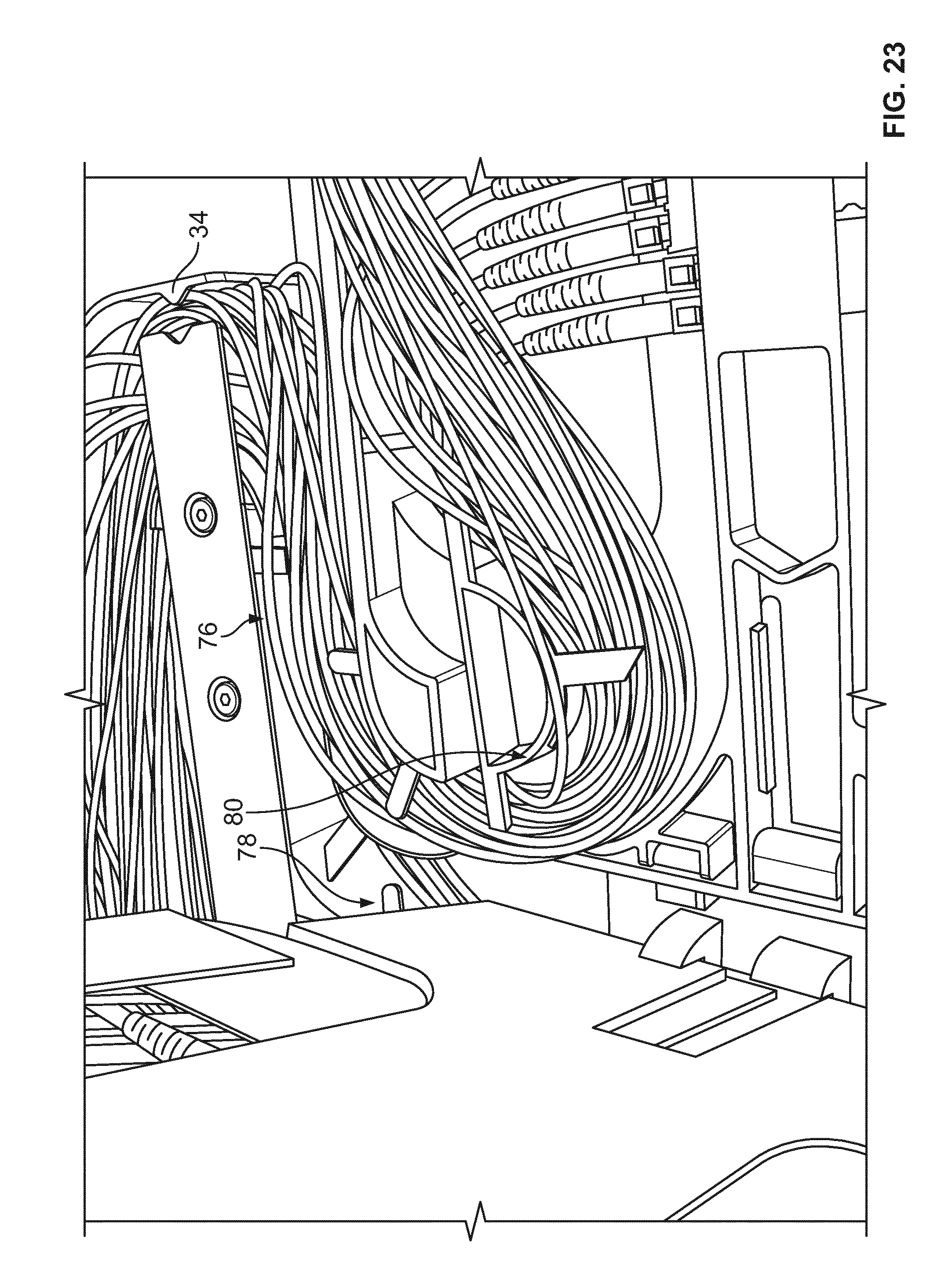
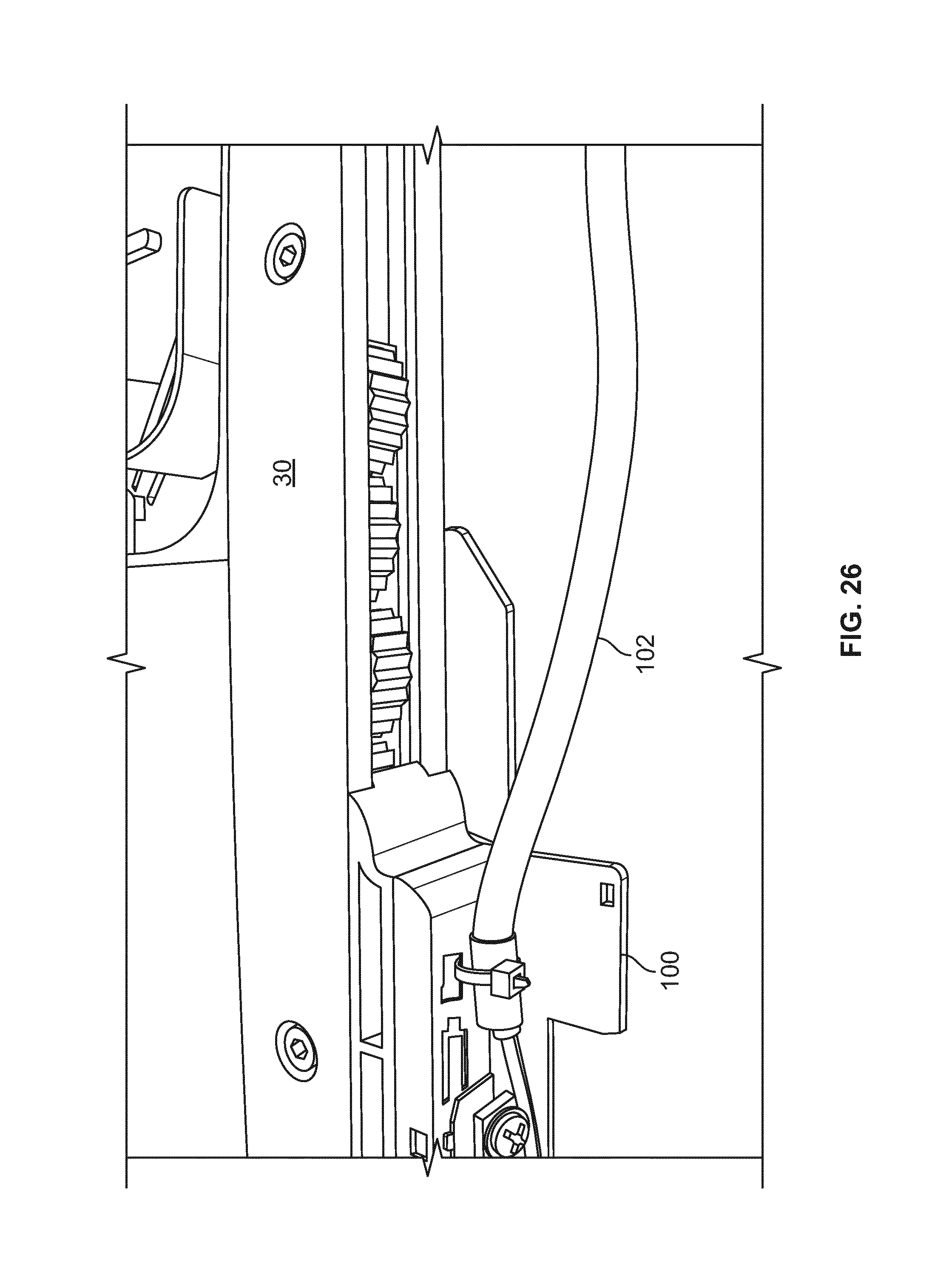
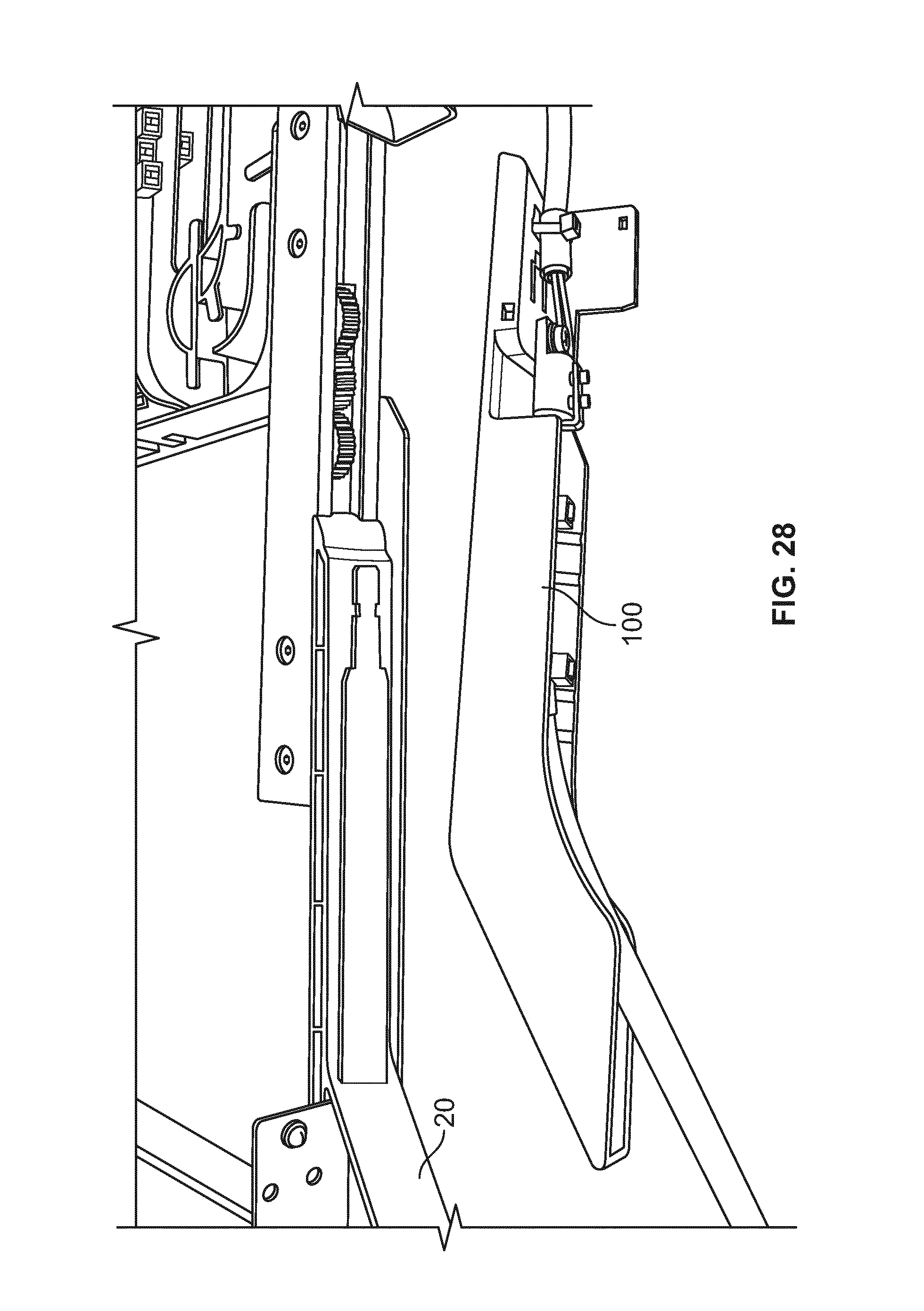
[0054] Each element includes a chassis 20 and a movable tray 24. Tray 24 is movable with a slide mechanism 30 including one or more gears 32 and a set of two toothed racks or linear members 34.
[0055] Slide mechanism 30 provides for synchronized movement for managing the cables extending to and from tray 24. Entry points 36 on either side of chassis 20 allow for fixation of the input and output cables associated with each element 10. The radius limiters 38 associated with each slide mechanism 30 move in synchronized movement relative to chassis 20 and tray 24 to maintain fiber slack, without causing fibers to be bent, pinched, or pulled.
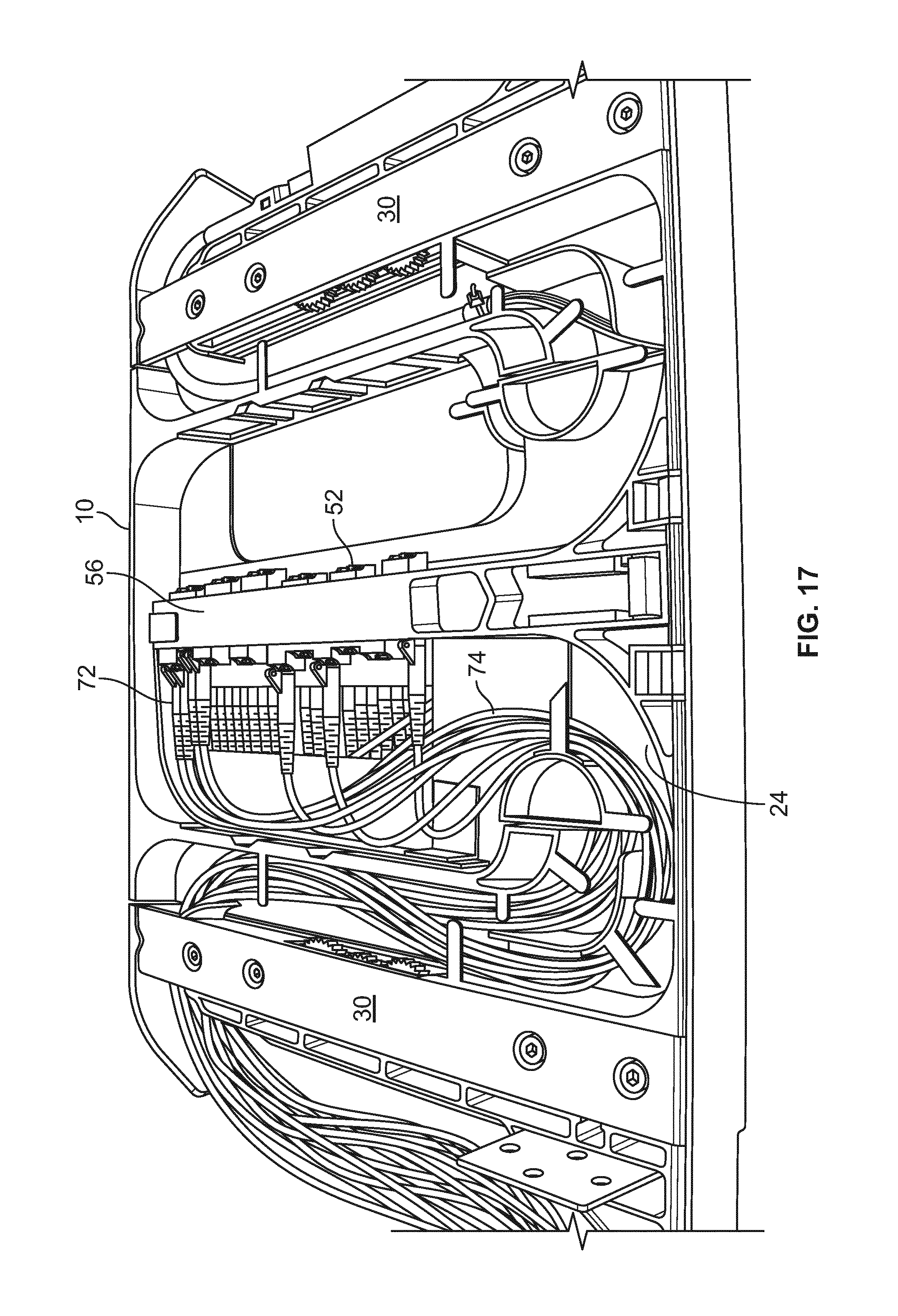
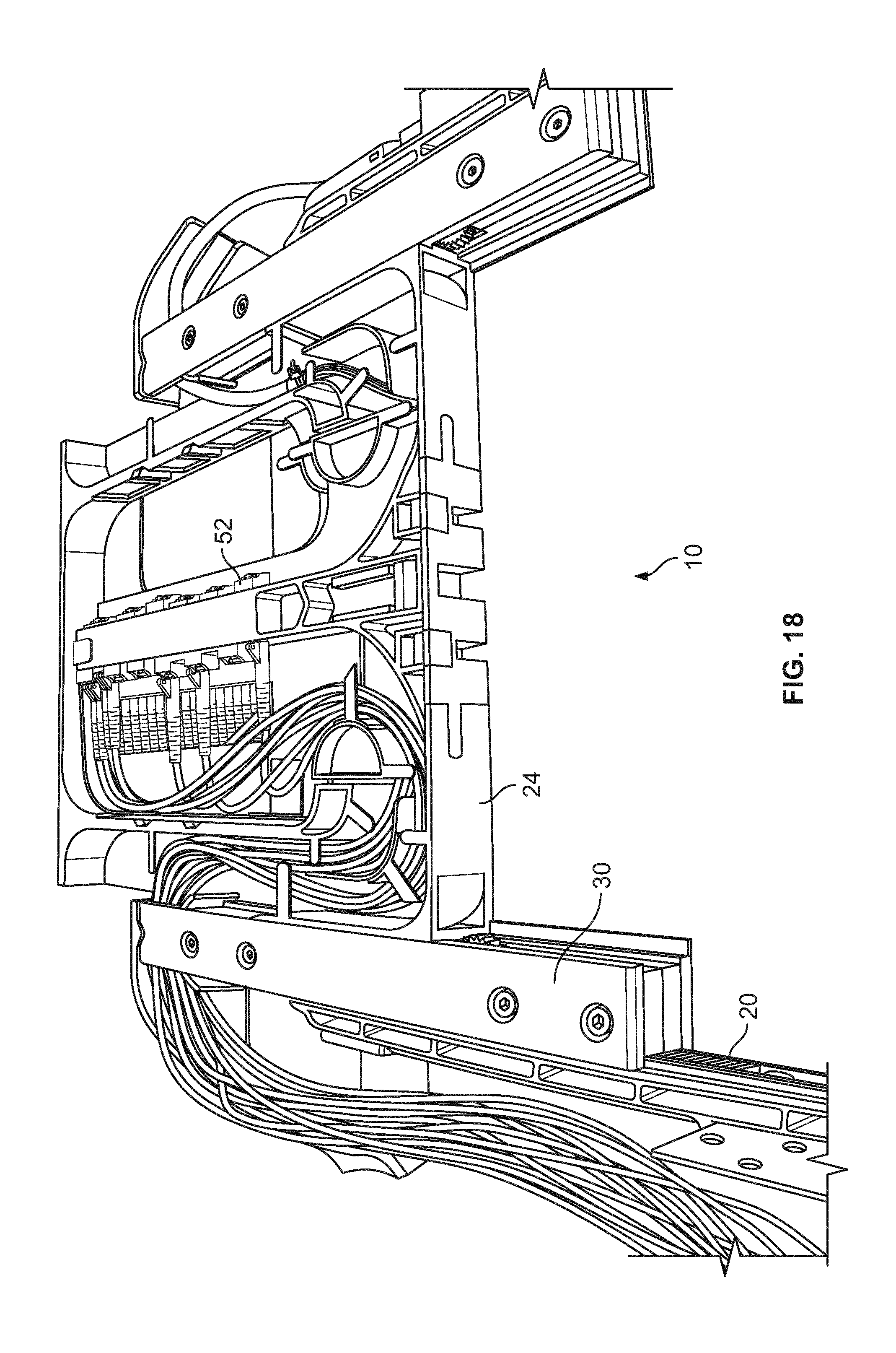
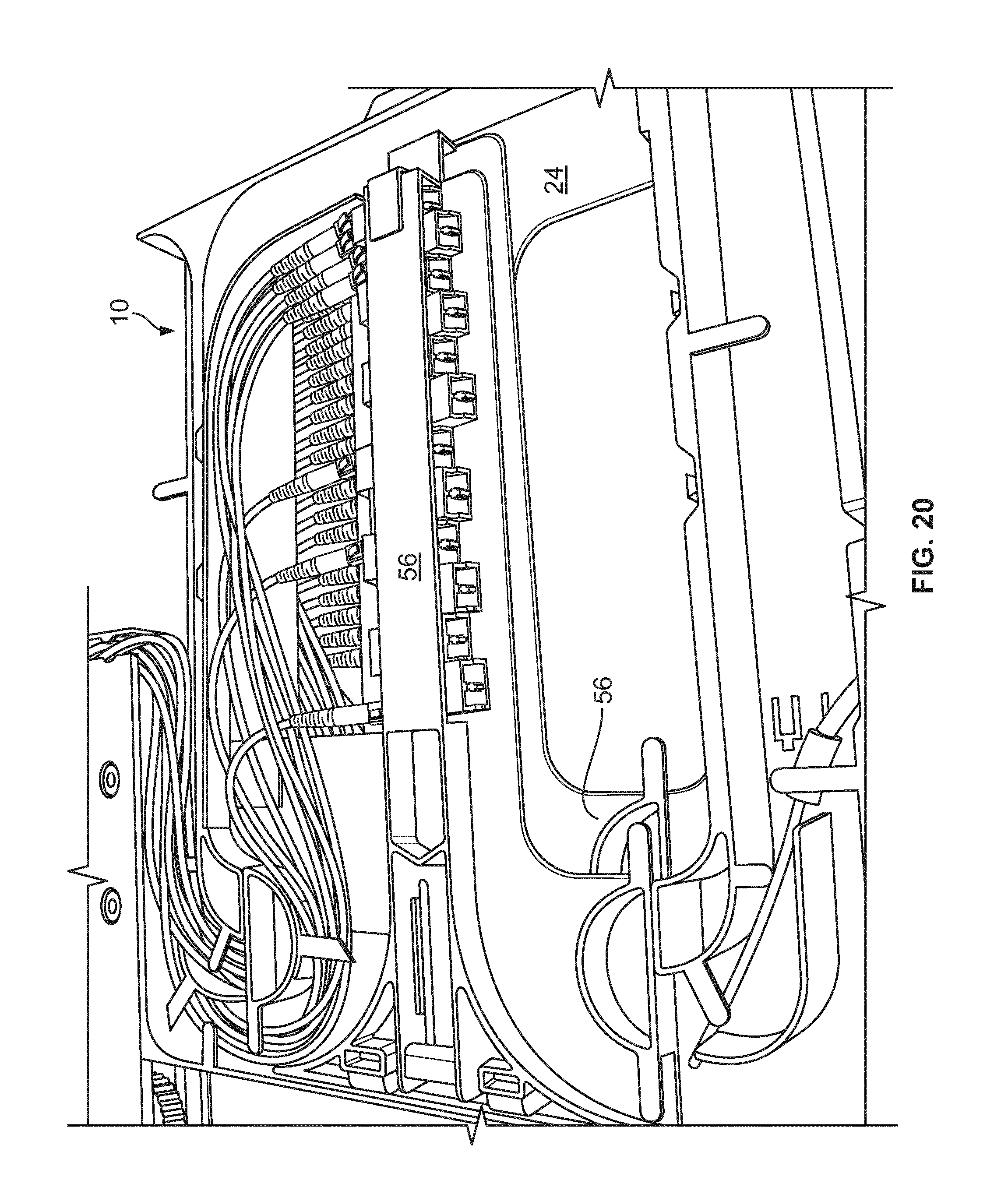
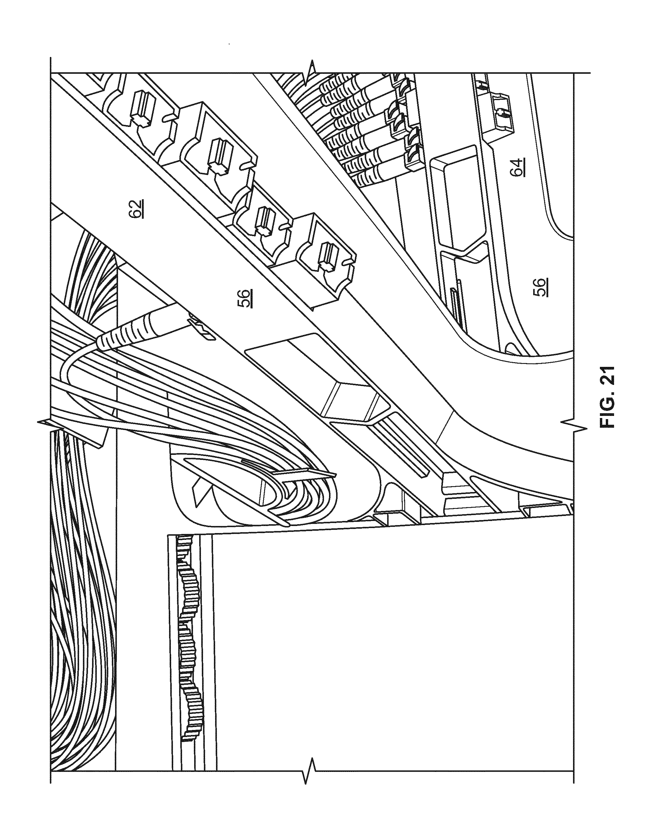
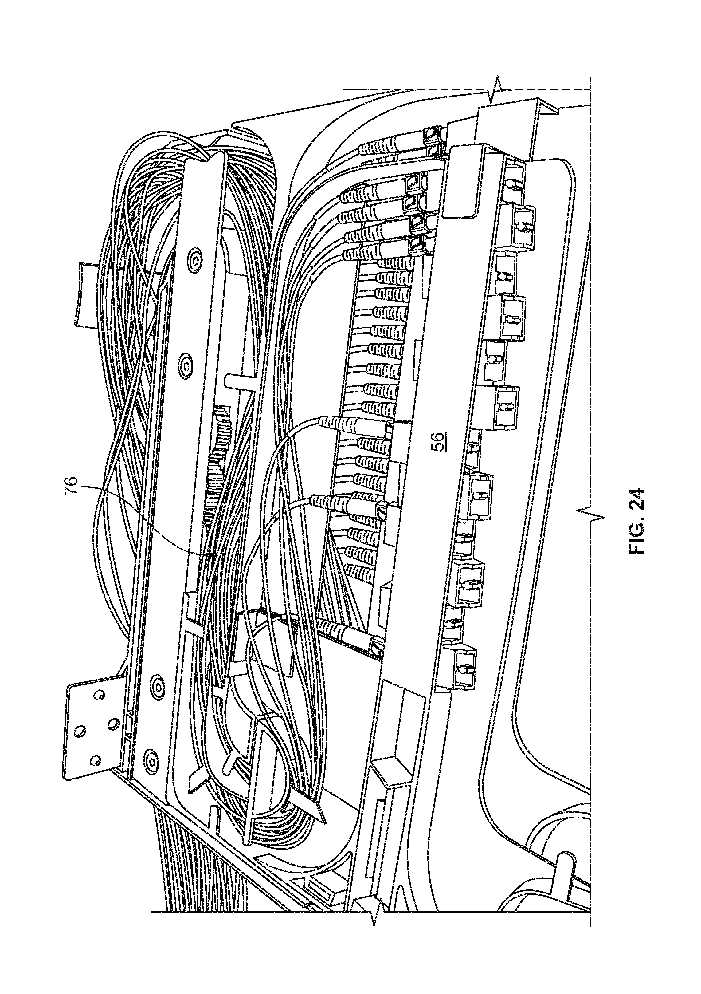
[0056] Each tray 24 includes mounting structure 50 defining one or more of fiber terminations, fiber splitters, fiber splices, or other fiber components. As shown, mounting structure 50 holds adapters 52 which allow for interconnection of two connectorized ends of cables. Each tray 24 includes one or more frame members 56. In the example shown, two frame members 56 are provided. As illustrated, each frame member 56 is T-shaped. Also, each tray 24 includes two frame members 56 which are hingedly mounted at hinges 58. A top frame member 62 is positioned above a bottom frame member 64. The mounting structure 50 associated with each frame member 62, 64 includes one or more integrally formed adapter blocks 70. Adapter blocks 70 include a plurality of adapter ports for interconnecting to fiber optic connectors 72. A pathway 76 defines a generally S-shape from radius limiters 38 to adapter blocks 70. As shown, pathway 76 includes an upper level 78 and a lower level 80 in the interior. A portion 84 of pathway 76 is positioned adjacent to hinges 58 to avoid potentially damaging cable pull during pivoting movement of frame members 56. Flanges 86 and radius limiters 90 help maintain cables 74 in pathways 76.
[0057] Tray 24 includes openings 96 to allow for technician access to the cable terminations at adapter blocks 70. In addition, the T-shapes of frame members 56 further facilitate technician access to the connectors 72.
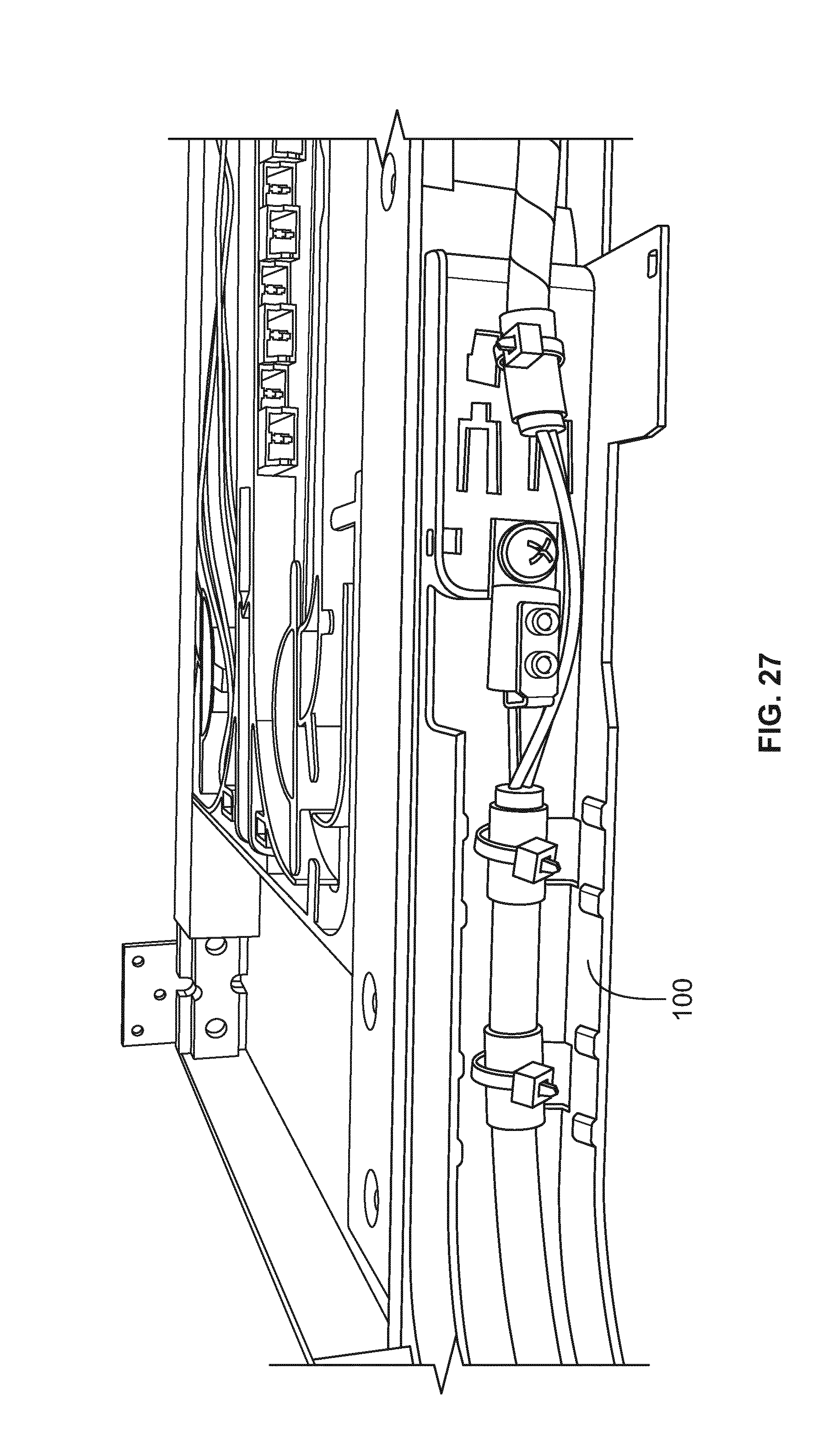
[0058] Cables 74 extending to and from element 10 can be affixed with a cable mount 100 as desired. Additional protection of the fiber breakouts can be handled with cable wraps 102. Radius limiters 106 can be additionally used to support and protect the cables 74.
[0059] Referring now to FIGS. 17-29, various examples of cable routings are illustrated for element 10.
[0060] If desired, more than one feeder cable can supply cabling to more than one element 10.
[0061] Referring now to FIGS. 30-41, various additional embodiments of elements 210 are shown. Element 210 includes a chassis 220 in a movable tray 224 mounted with a slide mechanism 230 which promotes synchronized movement of radius limiters 238. Each tray 224 includes two hingedly mounted frame members 256. Each frame member 256 has a middle portion 260 separated by openings 262 from side portions 264. Middle portion 260 can hold fiber terminations. Side portions 264 include radius limiters 270. Cover 266 goes over tray 224. Latches 268 latch tray 224 to cover 266 in the closed position.
[0062] A pathway 276 extends from either side from tray 224 to supply cables to each of trays 224. An upper level 278 and a lower level 280 supply the respective frame members 256 with cabling. A general S-shaped pathway 276 is defined wherein the pathway 276 passes close to hinges 258.
[0063] A dovetail 288 is used to hold cable mounts 286 and radius limiters 284.
[0064] An opening 290 in tray 224 allows for connector access by the technician. Similarly, openings 262 on each frame member 256 allow for technician access to the individual connectors.
[0065] To form a block 292 of plural elements 210, bars 294 and fasteners 296 are used. Bars 294 give a small spacing between each element 210.
[0066] Referring now to FIGS. 42-45, an alternative slide mechanism 330 is shown in alternative element 310. Slide mechanism 330 allows for movement of the trays and related radius limiters and synchronized movement similar to slide mechanism 30, 230. Alternative slide mechanism 330 includes two wheels 332 and two wires 334, 336. The wheels 332 are located on second part 342. The wires are looped in opposite directions and are connected to the first part 340 and the third part 344.
[0067] Referring now to FIGS. 46 and 47, an alternative radius limiter 420 is shown on alternative element 410. Radius limiter 420 includes friction members 430 which limit the amount of sliding movement of cables passing through radius limiter 420, to assist with cable management. Friction members 430 include flexible fingers which press lightly on the cables in radius limiter 420 to reduce or eliminate sliding movement of the cables in the radius limiter 420.
[0068] Referring now to FIGS. 48 and 49, an alternative element 510 is shown with a slide mechanism 530 which allows for synchronized movement of radius limiters 538 for cable management. Radius limiters 538 are also provided with a pivot feature to allow them to pivot rearwardly as the tray 524 is pulled out from chassis 520. Such rearward movement (pivot) allows for reduced pull on the cables, if pull is present, to allow the tray to be fully pulled out. Any angle can be provided. Fifteen degrees is one example angle.
[0069] Referring now to FIGS. 50 and 51, an alternative radius limiter 638 is shown on the slide mechanisms of alternative elements 610. Elements 610 are generally similar in construction and function to those of the elements discussed previously. Radius limiter 638 defines a generally U-shaped configuration that leads cables from and to the element 610 while preserving minimum bend radius requirements.
[0070] The U-shaped radius limiter 638 defines an inner end 621 and an outer end 623 and a divider 625 extending from adjacent the inner end 621 to adjacent the outer end 623. According to one embodiment, the divider 625 does not extend all the way to the inner and outer ends 621, 623 of the U-shaped radius limiter 638. The outer end 623 of the radius limiter 638 cooperates with a cable guide 684 that is mounted to the chassis 620 of the element 610 for leading cables to and from the tray 624 of the element 610.
[0071] The divider 625 of the radius limiter 638 forms two separate troughs 627, 629 for the radius limiter 638. The two troughs 627, 629 isolate and separate the cables (e.g., coming in and going out) of the element 610 into two distinct paths. According to one example cable routing configuration, the two troughs 627, 629 may guide the cables to the upper and lower levels 678, 680 defined toward the rear of the tray 624 while maintaining the S-shaped pathway 676 created within the element 610. The divider 625 of the radius limiter 638 includes a plurality of cable management tabs 631 mounted thereon for retaining the cables within the troughs 627, 629. A similar tab 633 is also found at the rear of the tray 624 for retaining the cables that are being lead to the upper and lower levels 678, 680. The tabs 631 and 633 may be removable, snap-on structures.
[0072] The tabs 631 and 633 cooperate with additional cable management fingers 635 defined both on the radius limiter 638 and toward the rear of the tray 624 in retaining the cables within the S-shaped pathway 676.
PARTS LIST
[0073] 10 element [0074] 12 block [0075] 20 chassis [0076] 24 tray [0077] 30 slide mechanism [0078] 32 gears [0079] 34 rack [0080] 36 entry points [0081] 38 radius limiters [0082] 50 mounting structure [0083] 52 adapters [0084] 56 T-shaped frame member [0085] 58 hinge [0086] 62 top frame member [0087] 64 bottom frame member [0088] 70 adapter blocks [0089] 72 connectors [0090] 74 cables [0091] 76 pathway [0092] 78 upper level [0093] 80 lower level [0094] 84 portion [0095] 86 flanges [0096] 90 radius limiters [0097] 96 openings [0098] 100 cable mount [0099] 102 cable wrap [0100] 106 radius limiters [0101] 210 element [0102] 220 chassis [0103] 224 tray [0104] 230 slide mechanism [0105] 238 radius limiters [0106] 256 frame members [0107] 258 hinges [0108] 260 middle portion [0109] 262 openings [0110] 264 side portions [0111] 266 cover [0112] 268 latches [0113] 270 radius limiters [0114] 276 pathway [0115] 278 upper level [0116] 280 lower level [0117] 284 radius limiters [0118] 286 cable mounts [0119] 288 dovetail [0120] 290 opening [0121] 292 block [0122] 294 bar [0123] 296 fasteners [0124] 310 element [0125] 330 slide mechanism [0126] 332 wheels [0127] 334 wire [0128] 336 wire [0129] 340 first part [0130] 342 second part [0131] 344 third part [0132] 410 element [0133] 420 radius limiter [0134] 430 friction members [0135] 510 element [0136] 520 chassis [0137] 524 tray [0138] 530 slide mechanism [0139] 538 radius limiters [0140] 610 element [0141] 620 chassis [0142] 621 inner end of radius limiter [0143] 623 outer end of radius limiter [0144] 624 tray [0145] 625 divider [0146] 627 trough [0147] 629 trough [0148] 631 cable management tab [0149] 633 cable management tab [0150] 635 cable management finger [0151] 638 radius limiter [0152] 676 pathway [0153] 678 upper level [0154] 680 lower level [0155] 684 cable guide
* * * * *
D00000
D00001
D00002
D00003
D00004
D00005
D00006
D00007
D00008
D00009
D00010
D00011
D00012
D00013
D00014
D00015
D00016
D00017
D00018
D00019

D00020
D00021
D00022
D00023
D00024
D00025
D00026
D00027
D00028
D00029

D00030
D00031
D00032
D00033
D00034
D00035
D00036

D00037
D00038
D00039

D00040
D00041
D00042
D00043
D00044
D00045
D00046
D00047
D00048

D00049

D00050
D00051
XML
uspto.report is an independent third-party trademark research tool that is not affiliated, endorsed, or sponsored by the United States Patent and Trademark Office (USPTO) or any other governmental organization. The information provided by uspto.report is based on publicly available data at the time of writing and is intended for informational purposes only.
While we strive to provide accurate and up-to-date information, we do not guarantee the accuracy, completeness, reliability, or suitability of the information displayed on this site. The use of this site is at your own risk. Any reliance you place on such information is therefore strictly at your own risk.
All official trademark data, including owner information, should be verified by visiting the official USPTO website at www.uspto.gov. This site is not intended to replace professional legal advice and should not be used as a substitute for consulting with a legal professional who is knowledgeable about trademark law.