Light Guide Plate and Surface-Lighting Device
KUGE; Morimasa ; et al.
U.S. patent application number 16/094185 was filed with the patent office on 2019-05-09 for light guide plate and surface-lighting device. The applicant listed for this patent is KAWASAKI JUKOGYO KABUSHIKI KAISHA. Invention is credited to Takanori KRITOSHI, Morimasa KUGE, Osami OOGUSHI, Hideyuki TANAKA.
| Application Number | 20190137680 16/094185 |
| Document ID | / |
| Family ID | 60116108 |
| Filed Date | 2019-05-09 |


View All Diagrams
| United States Patent Application | 20190137680 |
| Kind Code | A1 |
| KUGE; Morimasa ; et al. | May 9, 2019 |
Light Guide Plate and Surface-Lighting Device
Abstract
A light guide plate includes an incidence surface and an output surface. The incidence surface is an end surface on which light emitted from a light source is incident. The output surface is a surface from which incident light coming from the incidence surface is outputted, and is a plane orthogonal to a thickness direction. The incidence surface is at least partially curved toward the light source, when viewed in a cross-section cut along a plane parallel to both a thickness direction of the light guide plate and an arrangement direction in which the light source and the light guide plate are arranged.
| Inventors: | KUGE; Morimasa; (Kobe-shi, JP) ; KRITOSHI; Takanori; (Kobe-shi, JP) ; OOGUSHI; Osami; (Kobe-shi, JP) ; TANAKA; Hideyuki; (Kobe-shi, JP) | ||||||||||
| Applicant: |
|
||||||||||
|---|---|---|---|---|---|---|---|---|---|---|---|
| Family ID: | 60116108 | ||||||||||
| Appl. No.: | 16/094185 | ||||||||||
| Filed: | April 19, 2017 | ||||||||||
| PCT Filed: | April 19, 2017 | ||||||||||
| PCT NO: | PCT/JP2017/015757 | ||||||||||
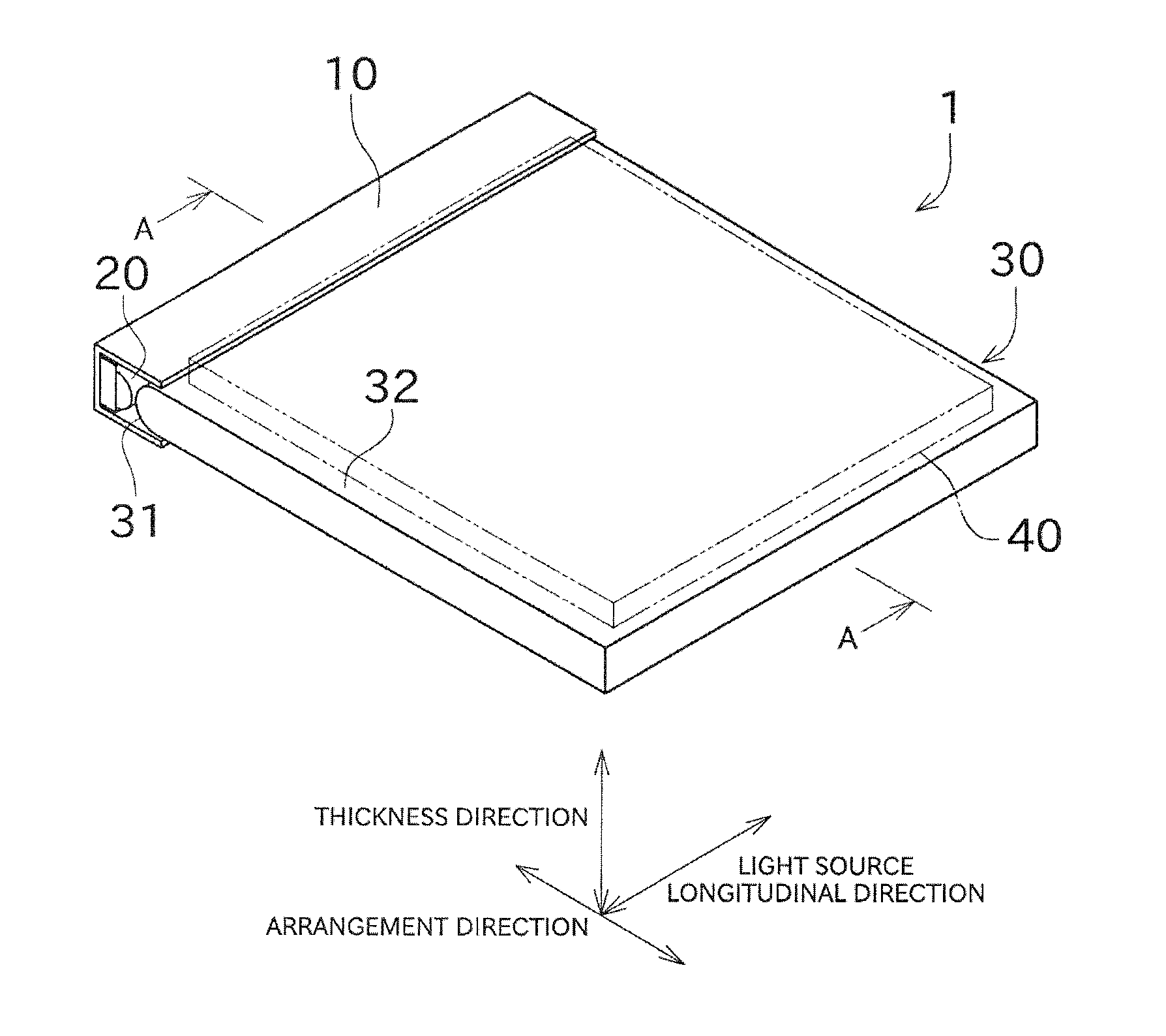
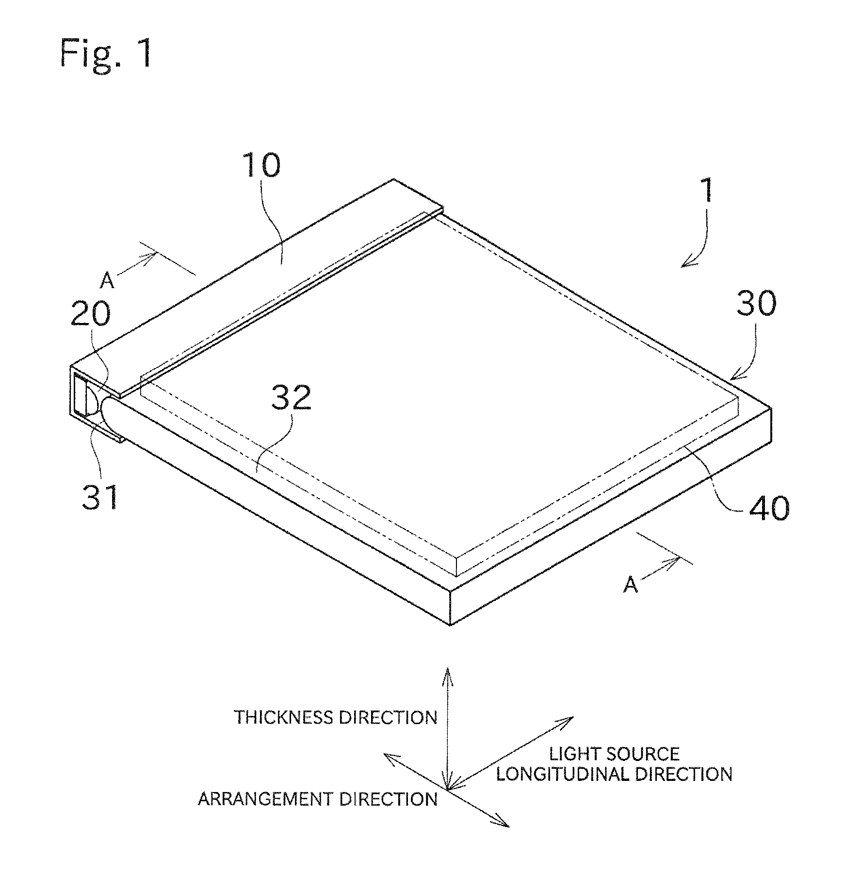
| 371 Date: | October 16, 2018 |
| Current U.S. Class: | 1/1 |
| Current CPC Class: | F21K 9/61 20160801; G02B 6/002 20130101; F21Y 2103/10 20160801; F21Y 2115/10 20160801; G02B 6/0045 20130101; F21Y 2111/00 20130101; G02B 6/0055 20130101; G02B 6/0051 20130101 |
| International Class: | F21V 8/00 20060101 F21V008/00; F21K 9/61 20060101 F21K009/61 |
Foreign Application Data
| Date | Code | Application Number |
|---|---|---|
| Apr 22, 2016 | JP | 2016-086507 |
Claims
1-6. (canceled)
7. A light guide plate, comprising: an incidence surface that is an end surface on which light from a light source is incident; and an output surface that is a surface from which incident light coming from the incidence surface is outputted, the output surface being a plane orthogonal to a thickness direction, wherein the incidence surface is at least partially curved toward the light source, when viewed in a cross-section cut along a plane parallel to both a thickness direction of the light guide plate and an arrangement direction in which the light source and the light guide plate are arranged.
8. The light guide plate according to claim 7, wherein in the cross-sectional view, the curve of the incidence surface has a circular arc shape or an elliptical arc shape.
9. The light guide plate according to claim 7, wherein in the cross-sectional view, a whole of the incidence surface is curved toward the light source.
10. The light guide plate according to claim 7, wherein an end surface opposite to the incidence surface is provided with a reflective surface that reflects incident light coming from the incidence surface toward inside of the light guide plate, and wherein in the cross-sectional view, the reflective surface is at least partially curved toward the side opposite to the incidence surface.
11. The light guide plate according to claim 7, wherein in the cross-sectional view, the output surface is at least partially bent or bendable.
12. A surface-lighting device, comprising: a light guide plate including an incidence surface that is an end surface on which light from a light source is incident; and an output surface that is a surface from which incident light coming from the incidence surface is outputted, the output surface being a plane orthogonal to a thickness direction, wherein the incidence surface is at least partially curved toward the light source, when viewed in a cross-section cut along a plane parallel to both a thickness direction of the light guide plate and an arrangement direction in which the light source and the light guide plate are arranged; and a light source emitting light to the incidence surface of the light guide plate.
Description
TECHNICAL FIELD
[0001] The present invention relates mainly to a light guide plate included in a surface-lighting device of edge-lighting type.
BACKGROUND ART
[0002] A surface-lighting device of edge-lighting type includes a light source and a light guide plate. The light source emits light to an end surface (side surface) of the light guide plate. The light emitted to the light guide plate is, while reflected within the light guide plate, uniformly outputted from another surface (output surface). By merely emitting light to the side surface of the light guide plate, the entire output surface can be made luminous. Patent Literature 1 (PTL 1) discloses a surface-lighting device of edge-lighting type.
[0003] PTL 1 discloses a surface-lighting device configured such that light emitted from a light source is reflected by a reflection member and then is incident on a light guide plate. According to PTL 1, a concave mirror can be used as the reflection member.
CITATION LIST
Patent Literature
[0004] PTL 1: WO2012/070331
SUMMARY OF INVENTION
Technical Problem
[0005] In the configuration shown in PTL 1, however, it is necessary to adjust positions of three components, namely, the light source, the reflection member, and the light guide plate. A risk that an optical path in the light guide plate may largely change arises when positioning of any of the light source, the reflection member, and the light guide plate is less accurate due to, for example, mispositioning during assemblage or a temperature change. The risk that the optical path in the light guide plate may largely change also arises when the shape of the reflection member or the light guide plate is less accurate. This results in a non-uniform light output from an output surface.
[0006] The present invention has been made in view of the circumstances described above, and a primary object of the present invention is to provide a light guide plate having an output surface with a high uniformity of illumination.
Solution to Problem
[0007] Problems to be solved by the present invention are as described above. Solutions to the problems and advantageous effects thereof will now be described.
[0008] A first aspect of the present invention provides a light guide plate configured as follows. The light guide plate includes an incidence surface and an output surface. The incidence surface is an end surface on which light from a light source is incident. The output surface is a surface from which incident light coming from the incidence surface is outputted, and is a plane orthogonal to a thickness direction. The incidence surface is at least partially curved toward the light source, when viewed in a cross-section cut along a plane parallel to both a thickness direction of the light guide plate and an arrangement direction in which the light source and the light guide plate are arranged.
[0009] This enables light incident on the incidence surface to be taken into the light guide plate with a traveling direction of the light being regulated. In addition, an optical path of the light taken through the incidence surface is changed toward a center with respect to the thickness direction, and therefore the number of times reflection occurs within the light guide plate increases. Accordingly, the uniformity of illumination of the output surface can be improved.
[0010] A second aspect of the present invention provides a surface-lighting device including the light guide plate and a light source that emits light to the incidence surface of the light guide plate.
[0011] This enables the output surface to be uniformly luminous without any need to dispose a light concentrator or the like between the light source and the light guide plate.
Advantageous Effects of Invention
[0012] The present invention can provide a light guide plate having an output surface with a high unifoi nity of illumination.
BRIEF DESCRIPTION OF DRAWINGS
[0013] FIG. 1 A perspective view showing a configuration of a surface-lighting device according to an embodiment of the present invention.
[0014] FIG. 2 A cross-sectional view of the surface-lighting device as taken along A-A.
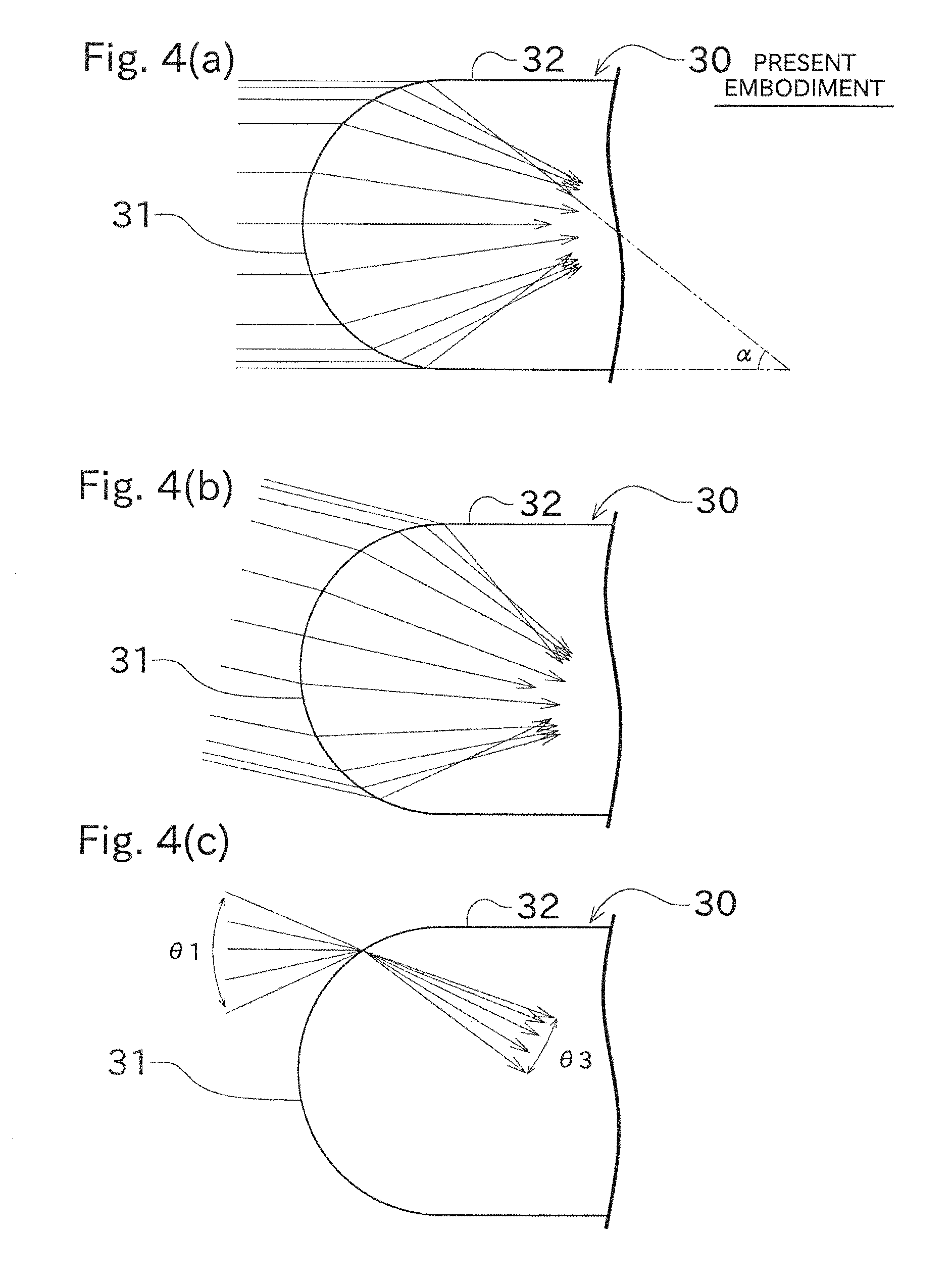
[0015] FIG. 3 Cross-sectional views of a light guide plate according to a conventional example, showing changes of optical paths obtained when parallel light rays (horizontal), parallel light rays (inclined), and light rays focusing to one point are emitted to the light guide plate.
[0016] FIG. 4 Cross-sectional views of a light guide plate according to this embodiment, showing changes of optical paths obtained when parallel light rays (horizontal), parallel light rays (inclined), and light rays focusing to one point are emitted to the light guide plate.
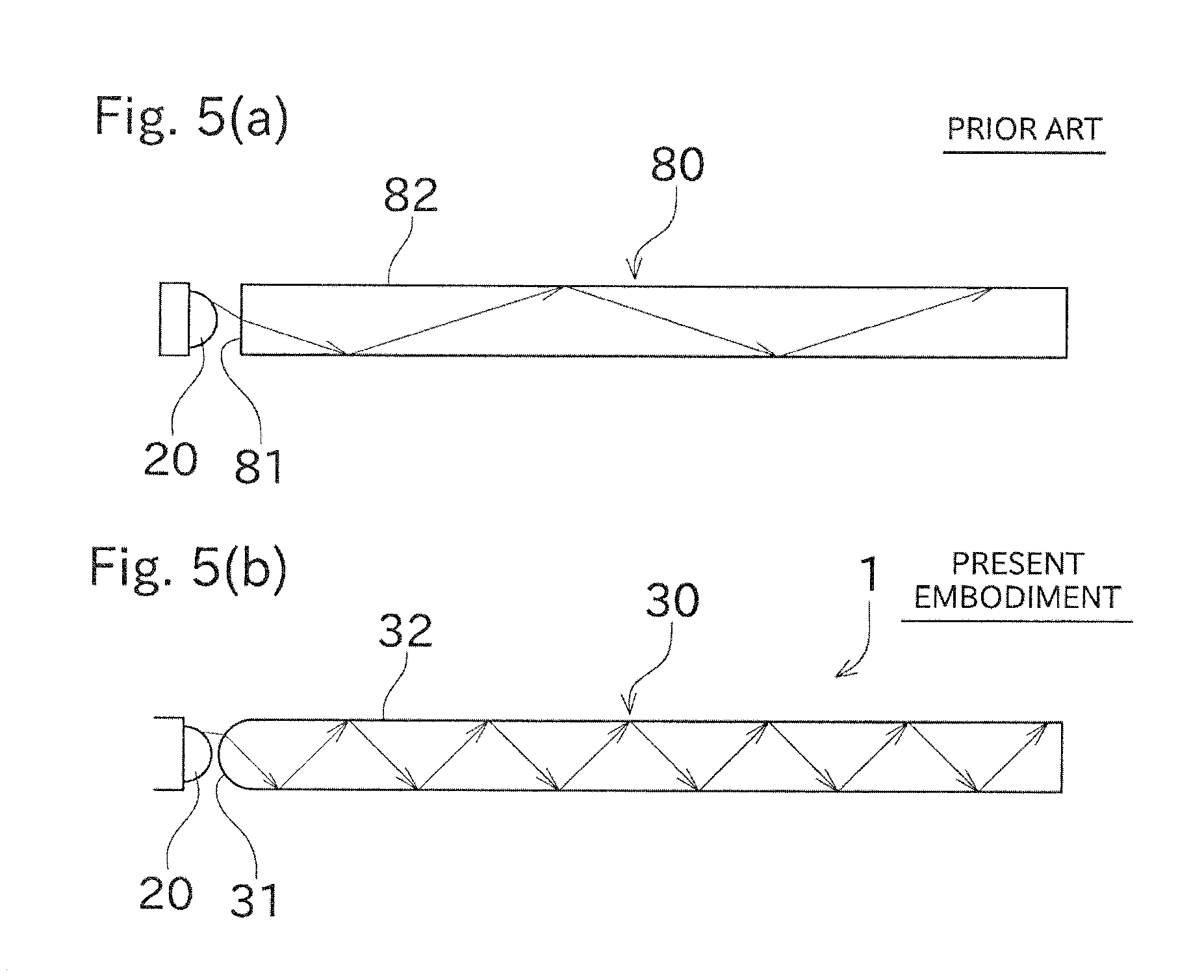
[0017] FIG. 5 Cross-sectional views schematically showing a difference between an optical path in the light guide plate according to this embodiment and an optical path in the light guide plate according to the conventional example.
[0018] FIG. 6 Cross-sectional views schematically showing a difference between a bendable light guide plate (first variation) and the light guide plate according to the conventional example.
[0019] FIG. 7 Cross-sectional views showing a configuration of a light guide plate (second variation) having a reflective surface.
[0020] FIG. 8 Cross-sectional views showing light guide plates (according to a third variation and a fourth variation) each having an incidence surface whose radius of curvature is greater than 1/2 of a plate thickness (convex curve).
[0021] FIG. 9 Cross-sectional views showing light guide plates (according to fifth to seventh variations) each having an incidence surface in the shape of an elliptical arc.
[0022] FIG. 10 Cross-sectional views showing light guide plates (according to eighth and ninth variations) each having an incidence surface that is partially curved.
[0023] FIG. 11 A perspective view showing a light guide plate (according to a tenth variation) having curved side surfaces.
DESCRIPTION OF EMBODIMENTS
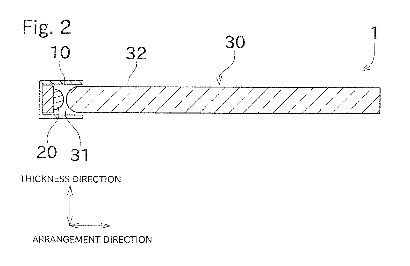
[0024] An embodiment of the present invention will now be described with reference to the drawings. First, referring to FIG. 1 and FIG. 2, a configuration of a surface-lighting device 1 will be described. FIG. 1 is a perspective view showing a configuration of the surface-lighting device 1 according to an embodiment of the present invention. FIG. 2 is a cross-sectional view of the surface-lighting device 1 as taken along A-A.
[0025] As shown in FIG. 1, the surface-lighting device 1 includes a light source holder 10, a light source 20, and a light guide plate 30. In the following description, a thickness direction of a light guide plate may be simply referred to as a thickness direction, and a direction in which the light source 20 and the light guide plate 30 are arranged may be simply referred to as an arrangement direction. A direction perpendicular to both the thickness direction and the arrangement direction will be referred to as a light source longitudinal direction.
[0026] The light source 20 includes a plurality of light-emitting elements (in this embodiment, light-emitting diodes) disposed along the light source longitudinal direction. Thus, the light source 20 is able to emit light to an object, i.e., the light guide plate 30, throughout the light guide plate 30 in the light source longitudinal direction. The light source 20 may include something other than light-emitting diodes. For example, the light source 20 may be a CCFL (cold cathode fluorescent lamp), a HCFL (hot cathode fluorescent lamp), or an EL (electroluminescent device). The configuration of the light source 20 is not limited to an arrangement of point light sources, and may be an arrangement of line light sources.
[0027] The light source holder 10 is configured such that the light source 20 is attachable thereto. The light source holder 10 is disposed so as to cover a space between the light source 20 and the light guide plate 30, and at least an inner surface of the light source holder 10 is made of a material capable of reflecting light. Due to this configuration, light emitted from the light source 20 is partially reflected by the inner surface of the light source holder 10, and is incident on the light guide plate 30. This can reduce a loss of the light emitted from the light source 20.
[0028] In this embodiment, the light guide plate 30 is a rectangular plate-shaped member. The light guide plate 30 may be made of any material as long as the material is light-transmissive. The material may be a resin such as an acrylic resin or a polycarbonate resin, or may be glass. As shown in FIG. 1, the light guide plate 30 has an incidence surface 31 and an output surface 32.
[0029] The incidence surface 31 is a side surface (end surface) of the light guide plate 30, which in other words is a surface parallel to the thickness direction (and also parallel to the light source longitudinal direction), or is a surface including a portion parallel to the thickness direction. The light guide plate 30 is disposed such that the incidence surface 31 is opposed to the light source 20 (in other words, such that a longitudinal direction of the incidence surface 31 is coincident with the light source longitudinal direction and such that a position of the light source 20 and a position of the incidence surface 31 with respect to the longitudinal direction are coincident with each other). With this configuration, light emitted from the light source 20 is incident on the substantially entire incidence surface 31 and inputted into the light guide plate 30.
[0030] As shown in FIG. 1 and FIG. 2, the incidence surface 31 is a curved surface. To be specific, in FIG. 2 (showing a cross-section cut along a plane parallel to both the thickness direction and the arrangement direction, or a cross-section cut along a plane orthogonal to the light source longitudinal direction), the incidence surface 31 is curved toward the light source 20. In this embodiment, the incidence surface 31 is in the shape of a circular arc (a circular sector having a central angle of 180.degree.) whose radius of curvature is 1/2 of a plate thickness of the light guide plate 30.
[0031] The incidence surface 31 with the shape of a curved surface can be formed by a machine work such as cutting or grinding, or can be formed with use of a mold. Alternatively, the incidence surface 31 can be formed by: melting an end surface of the light guide plate 30 and using a surface tension to make the end surface become a curved surface; and in this state, cool a resultant. Preferably, a surface of the incidence surface 31 is flat to such a degree that a light traveling direction is not disturbed upon incidence on the incidence surface 31. Advantages of the incidence surface 31 with the shape of a curved surface will be described later.
[0032] The output surface 32 is a surface of the light guide plate 30 (a surface perpendicular to the thickness direction, a surface including a portion perpendicular to the thickness direction, a surface having the largest area, or a principal plane). Light incident on the incidence surface 31 travels to an end surface (a right end surface in FIG. 2) opposite to the incidence surface 31 while being reflected within the light guide plate 30. In the course of the traveling, the light is outputted from the output surface 32 to the outside. This configuration enables substantially the whole of the output surface 32 to be luminous.
[0033] The surface-lighting device 1 of this embodiment is used as a backlight for a liquid crystal panel 40, as shown in FIG. 1. The liquid crystal panel 40 includes, for example, a liquid crystal layer, a color filter, a glass substrate, a polarizing film, and the like. With this configuration, just emitting light to the incidence surface 31 enables the liquid crystal panel to be uniformly irradiated with light.
[0034] To obtain a more uniform light output from the output surface 32, a diffusion sheet may be disposed between the light guide plate 30 and the liquid crystal panel 40. For the same purpose, a surface of the output surface 32 may have grooves, recesses, or protrusions. To prevent light from being outputted from a surface opposite to the output surface 32, the surface may be provided with a reflection sheet or a reflection plate.
[0035] Although the light guide plate 30 shown in FIG. 1 is in the shape of a rectangular plate, it may be in the shape of a square or other polygonal plate or in the shape of a circular plate. The light guide plate 30 is not limited to a flat plate, and may be a curved plate. In a case where the light guide plate 30 is a curved plate, the output surface 32 has a curved shape. Although the surface-lighting device 1 shown in FIG. 1 is configured to emit light to one end surface of the light guide plate 30, a configuration that emits light to two or more end surfaces is also acceptable. In addition, a configuration that emits light to a part of the incidence surface 31 is also acceptable as long as light is uniformly outputted from the output surface 32.
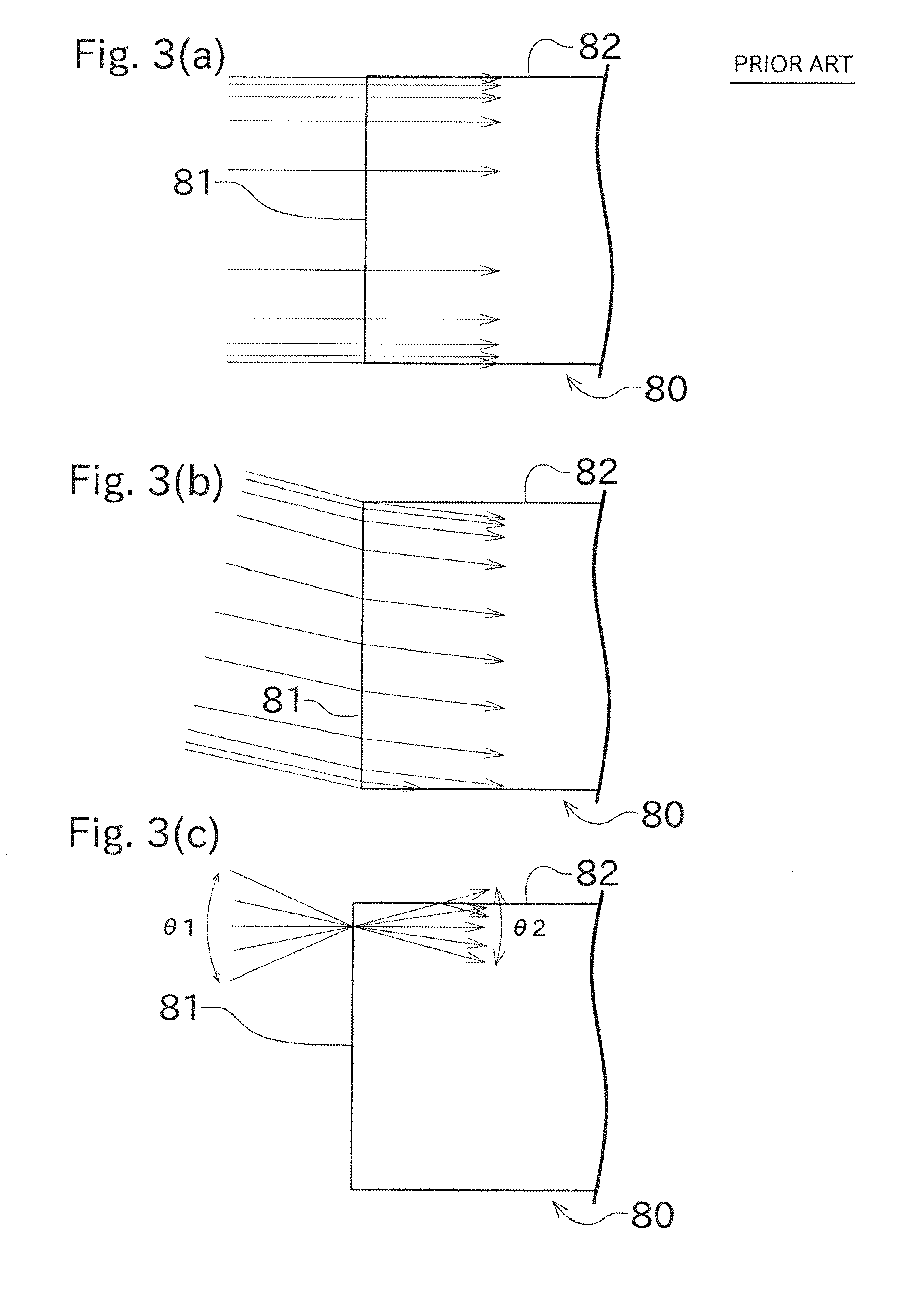
[0036] Referring to FIG. 3 to FIG. 5, advantages of a configuration in which the incidence surface 31 is curved toward the light source 20 will be described in comparison with a light guide plate 80 according to a conventional example. In cross-sectional views of FIG. 3 and subsequent figures, hatching is omitted for making the figures easy to see.
[0037] As shown in FIG. 3, the light guide plate 80 of the conventional example has an end surface that is planar (linear in the cross-sections of FIG. 3). Like the light guide plate 30, the light guide plate 80 has an incidence surface 81 and an output surface 82.
[0038] The light source 20 emits light rays in various traveling directions. The traveling directions are further changed upon the light rays being reflected by the inner surface of the light source holder 10. Thus, light rays in all traveling directions are incident on the incidence surface 31.
[0039] FIG. 3(a) shows changes of light traveling directions obtained when parallel light rays that are parallel to the output surface 82 are incident on the incidence surface 81 of the light guide plate 80 of the conventional example. When the parallel light rays that are parallel to the output surface 82 are incident on the light guide plate 80 of the conventional example, the light traveling directions are not changed. These light rays, therefore, are not outputted from the output surface 82.
[0040] FIG. 4(a) shows changes of light traveling directions obtained when parallel light rays that are parallel to the output surface 32 are incident on the incidence surface 31 of the light guide plate 30 of this embodiment. In the light guide plate 30 of this embodiment, the parallel light rays that are parallel to the output surface 32 pass through the incidence surface 31, and thereby their traveling directions are changed so as to be directed toward the inner side of the light guide plate 30 (toward the center with respect to the thickness direction). Thus, even when incident light rays are parallel to the output surface 32, these light rays are reflected within the light guide plate 80 during traveling, and therefore a part of the light rays is outputted from the output surface 32. Thus, effective use of the light of the light source 20 can be made. A light ray that is incident on an end portion of the incidence surface 31 with respect to the thickness direction is at an angle .alpha. (see FIG. 4(a)) relative to the output surface 32. Given that the light guide plate 30 is made of glass, this light ray is totally reflected, even at the angle .alpha..
[0041] FIG. 3(b) shows changes of light traveling directions obtained when parallel light rays that are inclined relative to the output surface 82 are incident on the incidence surface 81 of the light guide plate 80 of the conventional example. In the light guide plate 80 of the conventional example, the light traveling directions are changed such that their inclination angles relative to the output surface 82 are made smaller. As the inclination angles relative to the output surface 82 are smaller, the number of times reflection occurs within the light guide plate 80 decreases as shown in FIG. 5(a), which raises a risk that light outputted from the output surface 82 may be non-uniform.
[0042] FIG. 4(b) shows changes of light traveling directions obtained when parallel light rays that are inclined relative to the output surface 32 are incident on the incidence surface 31 of the light guide plate 30 of this embodiment. In the light guide plate 30 of this embodiment, the parallel light rays that are inclined relative to the output surface 32 pass through the incidence surface 31, and thereby their traveling directions are changed such that they are displaced toward the inner side of the light guide plate 30 (such that their inclination angles relative to the output surface 32 are made larger). As the inclination angles relative to the output surface 32 are larger, the number of times reflection occurs within the light guide plate 30 increases as shown in FIG. 5(b), which enables light outputted from the output surface 82 to be more uniform,
[0043] FIG. 3(c) shows changes of light traveling directions obtained when light rays focusing to one point on the incidence surface 81 are incident on the incidence surface 81. An angle .theta.1 represents a spread of light before the light is incident on the incidence surface 81. An angle .theta.2 represents a spread of light after the light is incident on the incidence surface 81. In the light guide plate 80 of the conventional example, a relationship of .theta.1>.theta.2 is established because of a difference in refractive index between air and the light guide plate 80.
[0044] FIG. 4(c) shows changes of light traveling directions obtained when light rays focusing to one point on the incidence surface 31 are incident on the incidence surface 31. An angle .theta.1 represents a spread of light before the light is incident on the incidence surface 31. An angle .theta.3 represents a spread of light after the light is incident on the incidence surface 31. A relationship of .theta.1>.theta.2>.theta.3 is established. In this embodiment, even when such light rays are incident, their traveling directions are changed such that their inclination angles relative to the output surface 32 are made larger. In this manner, light rays in various directions can be changed in such a direction that their inclination angles relative to the output surface 32 are made larger, and therefore the number of times reflection occurs within the light guide plate 30 increases, which enables light outputted from the output surface 82 to be more uniform.
[0045] The light guide plate 80 of the conventional example requires a detailed optical path design, one reason of which is that light does not reflect much within the light guide plate 80. For such designing, the positions and shapes of the light source 20 and the light guide plate 80 need to be highly accurate. In this respect, the light guide plate 80 of this embodiment, in which light rays in various directions can be changed in such a direction that their inclination angles relative to the output surface 32 are made larger, enables the output surface 32 to be uniformly luminous even if there is a slight mispositioning or misshaping.
[0046] A first variation of the embodiment described above will now be described with reference to FIG. 5. In descriptions of variations, members identical or similar to those of the embodiment described above will be given the same reference signs on the drawings, and their descriptions may be omitted.
[0047] In the embodiment described above, the light guide plate 30 is made of glass or the like, and has no flexibility. In the first variation, the light guide plate 30 is made of a resin composition such as silicone rubber, urethane rubber, or an acrylic resin, and has a flexibility.
[0048] In the light guide plate 80 of the conventional example, as mentioned above, light does not reflect much within the light guide plate 80, and therefore a detailed optical path design is made to arrange components with a high positioning accuracy so that light can be uniformly outputted from the output surface 82. In this configuration, however, merely slight bending of the light guide plate 80 causes a change in a light incidence angle, which causes a change of a reflection direction, resulting in a change of an optical path within the light guide plate 80. This makes it impossible to uniformly emit light from the output surface 82 (see FIG. 6(a)).
[0049] In the light guide plate 30 of the first variation, on the other hand, light rays in various directions can be changed in such a direction that their inclination angles relative to the output surface 32 are made larger. It therefore is possible that the output surface 32 is unifoinily luminous, even though the light guide plate 80 is bent (see FIG. 6(b)).
[0050] Although the light guide plate 30 of the first variation has a flexibility, the present invention is applicable also to a light guide plate 30 (a curved light guide plate) that is bent and that has no flexibility.
[0051] A second variation of the embodiment described above will now be described with reference to FIG. 7.
[0052] In the embodiment described above, the end surface opposite to the incidence surface 31 is linear, and a reflection plate, a reflection sheet, or the like are not provided. In the second variation, as shown in FIG. 7(a), an end surface (reflective surface 33) opposite to the incidence surface 31 is provided with a reflection plate which is capable of reflecting light incident thereon from the inside of the light guide plate 30. The reflective surface 33 is a curved surface curved toward the side opposite to the incidence surface 31. In other words, the reflective surface 33 is curved outward when viewed in a cross-section cut along a plane parallel to both the thickness direction and the arrangement direction.
[0053] With this configuration, light rays in various directions coming from the inside of the light guide plate 30 can be reflected in such a direction that their inclination angles relative to the output surface 32 are made larger, as shown in FIG. 7(b). As a result, the output surface 32 can be made uniformly luminous. In addition, the reflective surface 33 does not allow leakage of light, and thus efficient use of light emitted from the light source 20 can be made.
[0054] A third variation and a fourth variation will now be described with reference to FIG. 8.
[0055] In the embodiment described above, the incidence surface 31 has a circular arc shape whose radius of curvature is 1/2 of the plate thickness, when viewed in a cross-section cut along a plane parallel to both the thickness direction and the arrangement direction. In the third and fourth variations, on the other hand, the incidence surface 31 has a circular arc shape whose radius of curvature is larger than 1/2 of the plate thickness (convex-curve), when viewed in the same cross-section (FIG. 8). Here, the convex-curve represents such a shape that a plate end portion has a substantially spherical curved surface so that the light guide plate 30 as a whole has a spoon-like shape. This configuration contributes to an increased surface area of the incidence surface 31, and thus allows an increased amount of light to be taken into the light guide plate 30 as compared to the embodiment described above. As a result, the output surface 32 can be made brightly luminous. In particular, even when the size (thickness length) of the light source 20 is larger than the plate thickness of the light guide plate, the incidence surface 31 according to the third and fourth variations is able to take in a sufficient amount of light of the light source 20.
[0056] In the light guide plate 30 according to the third variation of FIG. 8(a), an end portion of the light guide plate 30 is worked to form the incidence surface 31, for example. There is no boundary between a circular arc shaped portion and a flat plate shaped portion. In the light guide plate 30 according to the fourth variation of FIG. 8(b), a semicircular columnar end surface portion 35 (whose cross-sectional contour is in the shape of a circular sector, or whose contour is partially in the shape of a circular arc) and a flat plate shaped light guide plate main body 34 (whose cross-sectional contour is in the shape of a rectangular) are joined to each other. The end surface portion 35, which is joined to the light guide plate main body 34, is a part constituting the light guide plate 30, and therefore can exert the same advantageous effects.
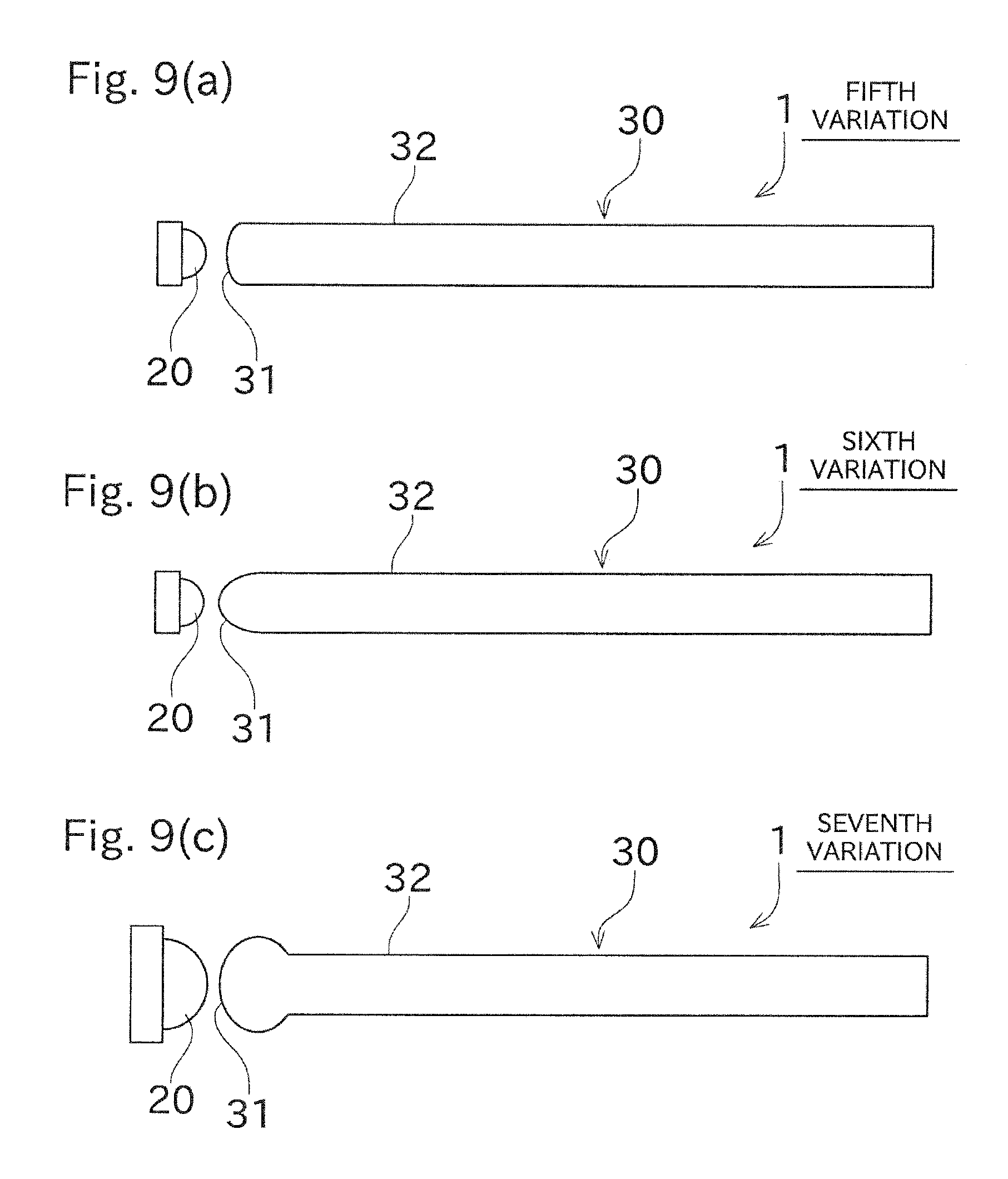
[0057] Fifth to seventh variations will now be described with reference to FIG. 9.
[0058] In the embodiment and variations described above, the incidence surface 31 has a circular arc shape in a cross-sectional view. In the fifth to seventh variations, the incidence surface 31 has an elliptical arc shape in a cross-sectional view. More specifically, in the fifth variation, the length of the major axis of an ellipse is equal to the plate thickness, and the length of the minor axis thereof is shorter than the plate thickness. In the sixth variation, the length of the minor axis of an ellipse is equal to the plate thickness, and the length of the major axis thereof is longer than the plate thickness. In the seventh variation, the length of the major axis of the ellipse is longer than the plate thickness.
[0059] The incidence surface 31 is simply required to be curved toward the light source 20 in a cross-sectional view, and may have any curved shape other than circular arcs and elliptical arcs.
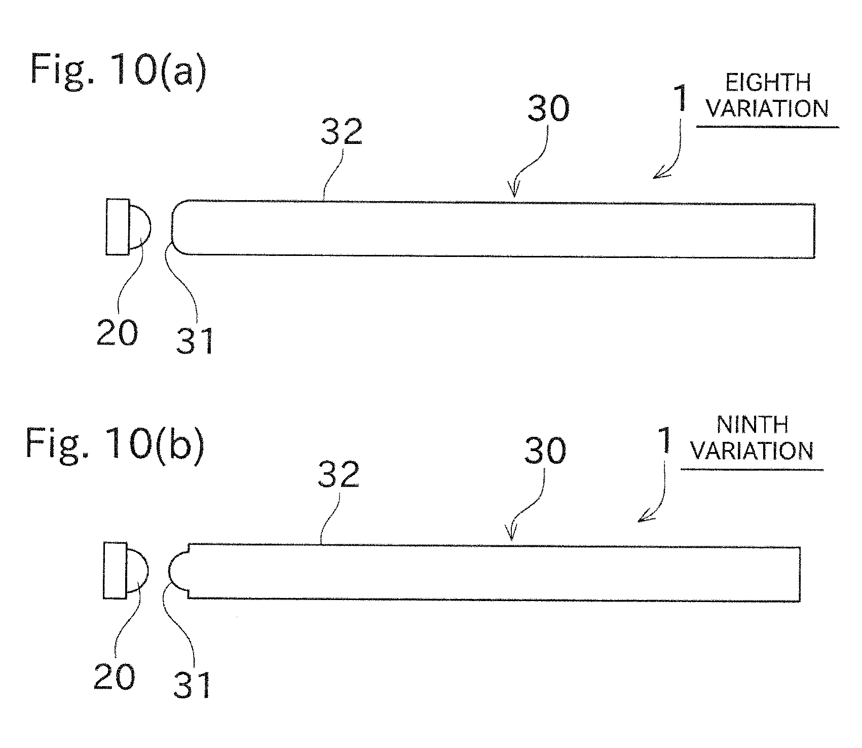
[0060] Eighth and ninth variations will now be described with reference to FIG. 10.
[0061] In the embodiment and variations described above, the whole of the incidence surface 31 is curved in a cross-sectional view. In the eighth and ninth variations, a part of the incidence surface 31 is curved in a cross-sectional view. More specifically, in the eighth variation, end portions of the incidence surface 31 with respect to the thickness direction are curved (curved toward the light source 20), and a middle portion of the incidence surface 31 with respect to the thickness direction is linear (linear along the thickness direction), in a cross-sectional view. In the ninth variation, end portions of the incidence surface 31 with respect to the thickness direction are linear (linear along the thickness direction), and a middle portion of the incidence surface 31 with respect to the thickness direction is curved (curved toward the light source 20), in a cross-sectional view.
[0062] A tenth variation will now be described with reference to FIG. 11.
[0063] In the embodiment and variations described above, side surfaces (surfaces perpendicular to the light source longitudinal direction, or surfaces extending in the arrangement direction) of the light guide plate 30 except the incidence surface 31 and the reflective surface 33 are flat surfaces. In the tenth variation, as shown in FIG. 11, such side surface 100 and side surface 101 are curved surfaces. More specifically, each of the side surfaces 100, 101 is, similarly to the incidence surface 31 or the like, configured to have a circular arc shape when viewed in a cross-section (a cross-section cut along a plane orthogonal to the arrangement direction). Here, the side surfaces 100, 101 are simply required to have cross-sections that are curved to protrude outward in the light source longitudinal direction, and the cross-sections may not necessarily be circular arcs. For example, shapes illustrated in other variations, such as elliptical arcs, may be adoptable.
[0064] Similarly to the second variation, each of the side surfaces 100, 101 is provided with a reflection plate or the like, and is capable of reflecting light incident thereon from the inside of the light guide plate 30. Accordingly, incident light coming from the incidence surface 31, which then travels from the inside of the light guide plate 30 toward the outside through the side surfaces 100, 101, can be returned to the inside of the light guide plate 30.
[0065] With this configuration, similarly to the second variation, light rays in various directions coming from the inside of the light guide plate 30 can be reflected in such a direction that their inclination angles relative to the output surface 32 are made larger. As a result, the output surface 32 can be made uniformly luminous.
[0066] While some variations have been described above, features of the variations can be combined as appropriate. For example, the first variation can be combined with at least one of the second to tenth variations (the same is true for the second and subsequent variations). To be specific, the light guide plate 30 having a flexibility (first variation) may be provided with the reflective surface 33 (second variation). A combination of the second variation and the tenth variation makes light leakage from the light guide plate 30 less likely to occur, thus enabling the output surface 32 to be more uniformly luminous.
[0067] As thus far described, the light guide plate 30 has the incidence surface 31 and the output surface 32. The incidence surface 31 is the end surface on which light from the light source 20 is incident. The output surface 32 is a surface from which incident light coming from the incidence surface 31 is outputted, and is a plane orthogonal to the thickness direction. The incidence surface 31 is at least partially curved toward the light source 20, when viewed in a cross-section cut along a plane parallel to both the thickness direction of the light guide plate 30 and the arrangement direction in which the light source 20 and the light guide plate 30 are arranged.
[0068] This enables light rays incident on the incidence surface 31 to be taken into the light guide plate 30 with traveling directions of the light rays being regulated. Furthermore, optical paths of the light rays taken through the incidence surface 31 are changed toward the center with respect to the thickness direction, and therefore the number of times reflection occurs within the light guide plate 30 increases, which can improve the uniformity of illumination of the output surface 32.
[0069] In a cross-sectional view of the light guide plate 30 described above, the curve of the incidence surface 31 has a circular arc shape or an elliptical arc shape.
[0070] The incidence surface 31 can be founed with a simple shape, it is easy to design optical paths, manufacture the light guide plate 30, and the like.
[0071] In a cross-sectional view of the light guide plate 30 described above, the whole of the incidence surface 31 is curved toward the light source 20.
[0072] This allows an increased amount of light to be incident on the curved surface, so that the advantageous effects of the present invention can be exerted more effectively.
[0073] In the light guide plate 30 described above, the end surface opposite to the incidence surface 31 is provided with the reflective surface 33 capable of reflecting incident light coming from the incidence surface 31 toward the inside of the light guide plate 30. In a cross-sectional view of the light guide plate 30, the reflective surface 33 is at least partially curved toward the side opposite to the incidence surface 31.
[0074] Accordingly, even though light taken through the incidence surface 31 reaches the reflective surface 33, the light is reflected toward the inside of the light guide plate 30, which enables effective use of the light emitted from the light source 20. In particular, the reflective surface 33 having the above-described shape is able to change optical paths of reflected light rays toward the center with respect to the thickness direction with traveling directions of the reflected light rays being regulated, in the same manner as the incident light rays. Consequently, the uniformity of illumination of the output surface 32 can be improved.
[0075] The light guide plate 30 described above is configured such that the output surface 32 is at least partially bent, or such that the light guide plate 30 is bendable.
[0076] In a case of the output surface 32 being bent, just a slight error causes a large change of optical paths. In a case of the light guide plate 30 being bendable, bending the light guide plate 30 causes a large change of optical paths. These features, therefore, make it difficult that the output surface 32 is uniformly luminous. In this embodiment, it is possible to make the output surface 32 uniformly luminous even with the light guide plate 30 having such a configuration, because the number of times reflection occurs within the light guide plate 30 is large.
[0077] While a preferred embodiment and variations of the present invention have been described above, the configurations described above may be modified, for example, as follows.
[0078] In the embodiment and variations described above, the incidence surface 31 is directly irradiated with light emitted from the light source 20. Alternatively, irradiation of the incidence surface 31 may be conducted with interposition of a mirror or the like. Even with such a configuration, the surface-lighting device 1 of this embodiment, which is not required to have as high a positioning accuracy as PTL 1, enables light to be uniformly outputted from the output surface 32.
[0079] In the embodiment and variations described above, the incidence surface 31 is symmetrical about a line passing through the center of the incidence surface 31 with respect to the thickness direction, but instead, the incidence surface 31 may be asymmetrical.
[0080] The embodiment described above illustrates an example case where the surface-lighting device 1 is applied to a backlight of a liquid crystal display. The surface-lighting device 1 may be applicable to other purposes. For example, the surface-lighting device 1 is applicable to a backlight of a guidance display, a poster, or the like. Applications of the surface-lighting device 1 are not limited to backlights.
REFERENCE SIGNS LIST
[0081] 1 surface-lighting device
[0082] 10 light source holder
[0083] 20 light source
[0084] 30 light guide plate
[0085] 31 incidence surface
[0086] 32 output surface
[0087] 33 reflective surface
* * * * *
D00000
D00001
D00002
D00003
D00004
D00005
D00006
D00007
D00008
D00009
D00010
D00011
XML
uspto.report is an independent third-party trademark research tool that is not affiliated, endorsed, or sponsored by the United States Patent and Trademark Office (USPTO) or any other governmental organization. The information provided by uspto.report is based on publicly available data at the time of writing and is intended for informational purposes only.
While we strive to provide accurate and up-to-date information, we do not guarantee the accuracy, completeness, reliability, or suitability of the information displayed on this site. The use of this site is at your own risk. Any reliance you place on such information is therefore strictly at your own risk.
All official trademark data, including owner information, should be verified by visiting the official USPTO website at www.uspto.gov. This site is not intended to replace professional legal advice and should not be used as a substitute for consulting with a legal professional who is knowledgeable about trademark law.