Heat Sink Structure
INAGAKI; Yoshikatsu ; et al.
U.S. patent application number 16/237283 was filed with the patent office on 2019-05-09 for heat sink structure. This patent application is currently assigned to FURUKAWA ELECTRIC CO., LTD.. The applicant listed for this patent is FURUKAWA ELECTRIC CO., LTD.. Invention is credited to Hirofumi AOKI, Yoshikatsu INAGAKI, Kenya KAWABATA, Daiki TAKEMURA.
| Application Number | 20190137187 16/237283 |
| Document ID | / |
| Family ID | 60787282 |
| Filed Date | 2019-05-09 |


View All Diagrams
| United States Patent Application | 20190137187 |
| Kind Code | A1 |
| INAGAKI; Yoshikatsu ; et al. | May 9, 2019 |
HEAT SINK STRUCTURE
Abstract
Provided is a heat sink structure which can reliably prevent blocking and narrowing of an inner space of the planar heat pipe thus having excellent heat transmission characteristics, and which can make cooling of a plurality of heat generating elements installed in a narrowed inner space uniform with a simple configuration. A heat sink structure has a planar heat pipe configured to be placed on a plurality of heat generating elements thus being thermally coupled to the plurality of heat generating elements; and a tubular heat pipe thermally coupled to a heat radiating portion of the planar heat pipe at a heat receiving portion of the tubular heat pipe.
| Inventors: | INAGAKI; Yoshikatsu; (Tokyo, JP) ; KAWABATA; Kenya; (Tokyo, JP) ; AOKI; Hirofumi; (Tokyo, JP) ; TAKEMURA; Daiki; (Tokyo, JP) | ||||||||||
| Applicant: |
|
||||||||||
|---|---|---|---|---|---|---|---|---|---|---|---|
| Assignee: | FURUKAWA ELECTRIC CO., LTD. Tokyo JP |
||||||||||
| Family ID: | 60787282 | ||||||||||
| Appl. No.: | 16/237283 | ||||||||||
| Filed: | December 31, 2018 |
Related U.S. Patent Documents
| Application Number | Filing Date | Patent Number | ||
|---|---|---|---|---|
| PCT/JP2017/024069 | Jun 30, 2017 | |||
| 16237283 | ||||
| Current U.S. Class: | 1/1 |
| Current CPC Class: | H01L 23/3672 20130101; H01L 23/467 20130101; F28D 2021/0029 20130101; F28F 2250/08 20130101; H01L 23/427 20130101; F28D 15/04 20130101; F28F 1/24 20130101; F28D 15/0233 20130101; F28D 15/0275 20130101; H05K 7/20336 20130101 |
| International Class: | F28D 15/02 20060101 F28D015/02 |
Foreign Application Data
| Date | Code | Application Number |
|---|---|---|
| Jul 1, 2016 | JP | 2016-131802 |
| Jul 1, 2016 | JP | 2016-131803 |
Claims
1. A heat sink structure comprising: a planar heat pipe configured to be placed on a plurality of heat generating elements thus being thermally coupled to the plurality of heat generating elements; and a tubular heat pipe thermally coupled to a heat radiating portion of the planar heat pipe at a heat receiving portion of the tubular heat pipe.
2. The heat sink structure according to claim 1, wherein a heat exchange unit is provided on a heat radiating portion of the tubular heat pipe.
3. The heat sink structure according to claim 2, wherein the heat exchange unit includes a heat radiating fin.
4. The heat sink structure according to claim 2, wherein at least one of the heat exchange unit and the heat radiating portion of the tubular heat pipe is cooled by cooling air from a blower fan.
5. The heat sink structure according to any one of claims 1, wherein a biasing member is provided on the planar heat pipe, and the biasing member is fixed to a support member of the heat generating element.
Description
CROSS REFERENCE TO RELATED APPLICATIONS
[0001] This is a continuation application of international patent Application No. PCT/JP2017/024069 filed Jun. 30, 2017, which claims the benefit of Japanese Patent Application No. 2016-131802, filed Jul. 1, 2016, and Japanese Patent Application No. 2016-131803, filed Jul. 1, 2016, the full contents of both of which are hereby incorporated by reference in their entirety.
BACKGROUND
Technical Field
[0002] The present disclosure relates to a heat sink structure having excellent cooling performance with respect to a plurality of heat generating elements installed in a narrow inner space, for example, in an inner space having a small size in the thickness direction. The present disclosure also relates to a heat sink structure having excellent cooling performance with respect to heat generating elements installed in a narrow inner space.
Background
[0003] An electronic component mounted on an electric or electronic device, such as a semiconductor element, increases in amount of heat generation due to high-density mounting or the like caused by enhanced functions. Accordingly, in recent years, it is considered important to cool the component. Further, miniaturization, thinning or the like of the electric or electronic device causes an inner space of a casing of the electric or electronic device to be further narrowed. A planar heat pipe may be used as a cooling unit for an electronic component installed in the narrowed inner space.
[0004] As the cooling structure for an electronic component installed in an inner space having a small size in the thickness direction, a cooling structure is proposed which includes: a first heat generating element provided in a casing; a heat sink provided in the casing; a first pressing member; a plate-like first heat pipe which has a first portion opposedly facing the first heat generating element and a second portion displaced from the first heat generating element, the first heat pipe being bent with the press of the first pressing member; and a second heat pipe which includes a tubular container coupled to the second portion of the first heat pipe and to the heat sink (Japanese Patent Application Laid-Open No. 2011-106793).
[0005] According to Japanese Patent Application Laid-Open No. 2011-106793, in the case where a second heat generating element is provided in the casing, the cooling structure further includes, in addition to the plate-like first heat pipe, a plate-like third heat pipe which has a first portion opposedly facing the second heat generating element, and a second portion displaced from the second heat generating element and coupled to the second heat pipe.
[0006] However, in the technique disclosed in Japanese Patent Application Laid-Open No. 2011-106793, the plate-like heat pipe is bent, that is, deformed in the direction perpendicular to a planar surface with the press of the pressing member. Accordingly, in the plate-like heat pipe where the container has a small thickness, an inner space, particularly, a space in the thickness direction, of the heat pipe is blocked or narrowed and hence, a function of the heat pipe, that is, heat transmission characteristics, is impaired.
[0007] In the technique disclosed in Japanese Patent Application Laid-Open No. 2011-106793, to cool the plurality of heat generating elements, plate-like heat pipes which are formed of separate bodies are required to be coupled to the heat generating elements respectively, and the respective plate-like heat pipes are required to be coupled to the second heat pipe which is a main heat pipe having a tubular container. Accordingly, it is necessary to adjust a size of each plate-like heat pipe according to the position of a heat generating element. Therefore, the number of parts increases and, at the same time, the structure is complicated.
[0008] Further, in the technique disclosed in Japanese Patent Application Laid-Open No. 2011-106793, the plate-like heat pipes which are formed of the separate bodies are respectively coupled to the heat generating elements. Accordingly, when the plurality of heat generating elements have different amounts of heat generation, particularly, a heat generating element having a large amount of heat generation may not be sufficiently cooled.
SUMMARY
[0009] The present disclosure is related to providing a heat sink structure which can reliably prevent blocking and narrowing of an inner space of the planar heat pipe thus having excellent heat transmission characteristics, and which can make cooling of a plurality of heat generating elements installed in a narrowed inner space uniform with a simple configuration. The present disclosure is also related to providing a heat sink structure which has excellent heat transmission characteristics and functions as a soaking plate with respect to heat generating elements installed in a narrowed inner space with a simple configuration thus exhibiting excellent cooling performance.
[0010] An aspect of the present disclosure is directed to a heat sink structure which includes: a planar heat pipe configured to be placed on a plurality of heat generating elements thus being thermally coupled to the plurality of heat generating elements; and a tubular heat pipe thermally coupled to a heat radiating portion of the planar heat pipe at a heat receiving portion of the tubular heat pipe.
[0011] In the above-mentioned aspect, placement of the planar heat pipe on the plurality of heat generating elements allows the planar heat pipe to be thermally coupled to the plurality of heat generating elements and to be fixed to the heat generating elements. In the above-mentioned aspect, portions of the planar heat pipe to which the heat generating elements are thermally coupled function as heat receiving portions. A portion of the planar heat pipe to which the tubular heat pipe is thermally coupled functions as a heat radiating portion. A portion of the tubular heat pipe to which the planar heat pipe is thermally coupled functions as a heat receiving portion. Further, in the above-mentioned aspect, the plurality of heat generating elements are thermally coupled to the planar heat pipe and hence, the plurality of heat generating elements are thermally coupled to one planar heat pipe, that is, to the same planar heat pipe.
[0012] Another aspect of the present disclosure is directed to the heat sink structure where a heat exchange unit is provided on a heat radiating portion of the tubular heat pipe.
[0013] Another aspect of the present disclosure is directed to the heat sink structure where the heat exchange unit includes a heat radiating fin.
[0014] Another aspect of the present disclosure is directed to the heat sink structure where at least one of the heat exchange unit and the heat radiating portion of the tubular heat pipe is cooled by cooling air from a blower fan.
[0015] Another aspect of the present disclosure is directed to the heat sink structure where a biasing member is provided on the planar heat pipe, and the biasing member is fixed to a support member of the heat generating element.
[0016] An aspect of the present disclosure is directed to a heat sink structure which includes a planar heat pipe, and a tubular heat pipe thermally coupled to the planar heat pipe, wherein a heat generating element is thermally coupled to the position where the planar heat pipe and the tubular heat pipe overlap with each other as viewed in a plan view.
[0017] In the above-mentioned aspect, the heat generating element is coupled to the planar heat pipe or to the tubular heat pipe. In this specification, "as viewed in a plan view" means a state which is visually recognized in the direction perpendicular to a planar portion of the planar heat pipe.
[0018] Another aspect of the present disclosure is directed to the heat sink structure where the tubular heat pipe is disposed on the side of the planar heat pipe closer to the heat generating element. In the above-mentioned aspect, the heat generating element is coupled to the tubular heat pipe.
[0019] Another aspect of the present disclosure is directed to the heat sink structure where the planar heat pipe is disposed on the side of the tubular heat pipe closer to the heat generating element. In the above-mentioned aspect, the heat generating element is coupled to the planar heat pipe.
[0020] Another aspect of the present disclosure is directed to the heat sink structure where a heat exchange unit is provided on a heat radiating portion of the tubular heat pipe.
[0021] Another aspect of the present disclosure is directed to the heat sink structure where the heat exchange unit includes a heat radiating fin.
[0022] Another aspect of the present disclosure is directed to the heat sink structure where at least one of the heat exchange unit and the heat radiating portion of the tubular heat pipe is cooled by cooling air from the blower fan.
[0023] According to the aspect of the present disclosure, placement of the planar heat pipe on the plurality of heat generating elements allows the planar heat pipe to be thermally coupled to the plurality of heat generating elements. Accordingly, blocking and narrowing of an inner space of the planar heat pipe can be reliably prevented and, as a result, the heat sink structure can exhibit excellent heat transmission characteristics.
[0024] According to the aspect of the present disclosure, the plurality of heat generating elements are thermally coupled to one planar heat pipe and hence, the number of parts of the planar heat pipe can be reduced and, at the same time, the structure can be simplified. According to the aspect of the present disclosure, the plurality of heat generating elements are thermally coupled to one planar heat pipe, and the planar heat pipe is thermally coupled to the tubular heat pipe having excellent heat transmission characteristics in the predetermined direction. Accordingly, even when the plurality of heat generating elements have different amounts of heat generation, the planar heat pipe can make heating of the respective heat generating elements uniform thus making cooling of the respective heat generating elements uniform. Further, according to the aspect of the present disclosure, the heat generating element is thermally coupled to the planar heat pipe and hence, the heat sink structure can even reliably cool heat generating elements installed in a narrow inner space, for example, in an inner space having a small size in the thickness direction.
[0025] According to the aspect of the present disclosure, the heat exchange unit is provided on the heat radiating portion of the tubular heat pipe and hence, heat dissipation characteristics of the tubular heat pipe is enhanced so that the heat sink structure can even reliably cool heat generating elements installed in a narrow inner space.
[0026] According to the aspect of the present disclosure, the planar heat pipe and the tubular heat pipe are thermally coupled to each other. Accordingly, the tubular heat pipe is operated in a state where heat from the heat generating element diffuses on a surface of the planar heat pipe thus increasing a heat dissipation area. Further, the heat generating element is thermally coupled to the position where the planar heat pipe and the tubular heat pipe overlap with each other and hence, heat is smoothly transferred from the heat generating element to the tubular heat pipe. Accordingly, the heat sink structure of the present disclosure has excellent heat transmission characteristics and functions as a soaking plate thus exhibiting excellent cooling performance with respect to the heat generating elements.
[0027] According to the aspect of the present disclosure, in cooling a plurality of heat generating elements which have different amounts of heat generation, a heat generating element having a relatively small amount of heat generation can be cooled by the planar heat pipe having a function as a soaking plate. Accordingly, a heat transmission amount of the tubular heat pipe can be reduced by a corresponding amount.
[0028] According to the aspect of the present disclosure, the planar heat pipe is used, and the number of heat generating elements to be thermally coupled is not particularly limited. Accordingly, the heat sink structure can exhibit excellent cooling performance with respect to heat generating elements installed in a narrowed inner space with a simple configuration.
[0029] According to the aspect of the present disclosure, the tubular heat pipe is disposed on the side of the planar heat pipe closer to the heat generating elements and hence, heat from the heat generating elements is smoothly transferred to the tubular heat pipe. Further, the heat from the heat generating elements which is transferred to the planar heat pipe through the tubular heat pipe diffuses on the surface of the planar heat pipe due to a function of the planar heat pipe as a soaking plate thus increasing a heat dissipation area. Accordingly, in the above-mentioned aspect, a heat transmission amount of the tubular heat pipe can be reduced and, therefore, the tubular heat pipe can be flattened (thinned) and reduced in diameter. As described above, the tubular heat pipe can be flattened and reduced in diameter and hence, the heat sink structure can be further miniaturized.
[0030] According to the aspect of the present disclosure, the planar heat pipe is disposed on the side of the tubular heat pipe closer to the heat generating elements and hence, heat from the heat generating elements first diffuses on the surface of the planar heat pipe due to a function of the planar heat pipe as a soaking plate and, then, is transferred to the tubular heat pipe. Accordingly, the generation of a hot spot in the planar heat pipe can be prevented. As described above, the generation of a hot spot in the planar heat pipe can be prevented and hence, the heat sink structure can exhibit excellent cooling performance with respect to the heat generating elements.
[0031] According to the aspect of the present disclosure, the heat exchange unit is provided on the heat radiating portion of the tubular heat pipe and hence, heat dissipation characteristics of the tubular heat pipe is enhanced so that the heat sink structure can even reliably cool heat generating elements installed in a narrow inner space.
BRIEF DESCRIPTION OF THE DRAWINGS
[0032] FIG. 1 is an explanatory view of a heat sink structure according to a first embodiment of the present disclosure as viewed in a side view;
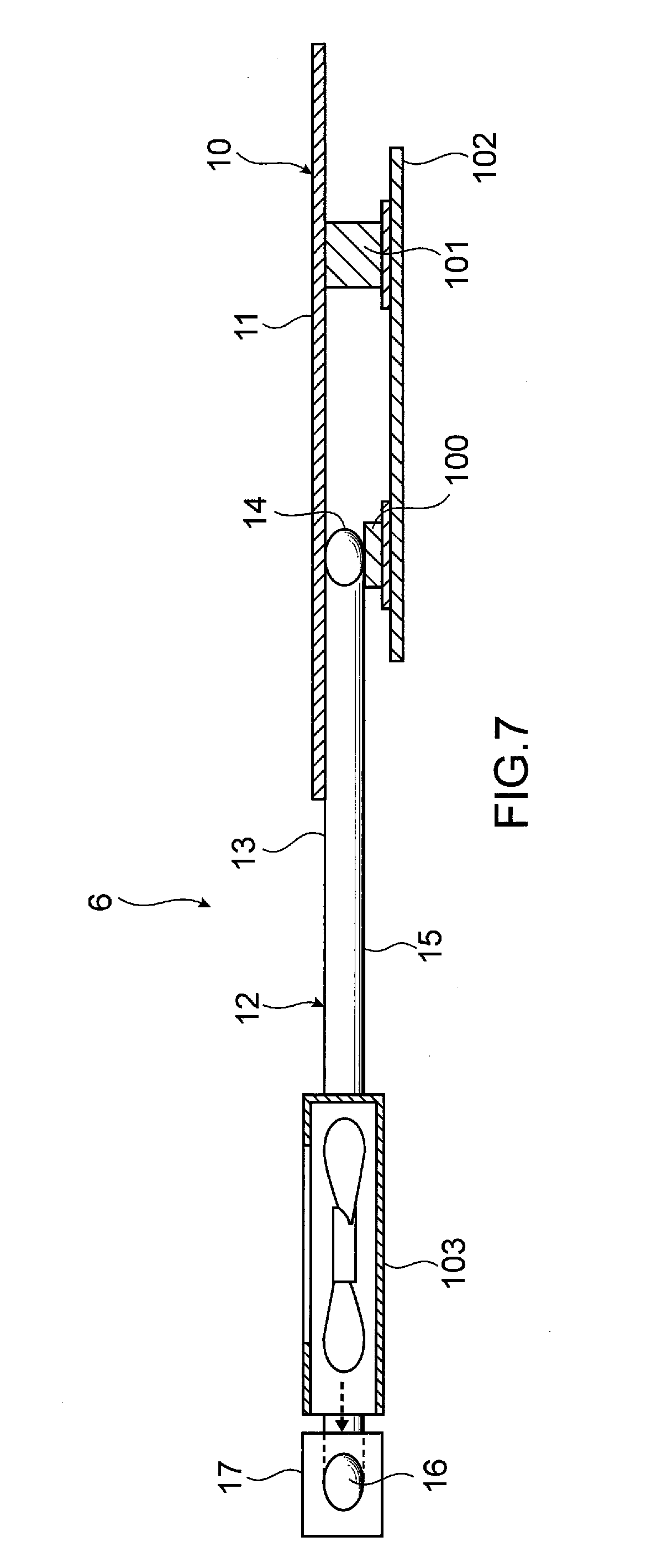
[0033] FIG. 2 is an explanatory view of the heat sink structure according to the first embodiment of the present disclosure as viewed in a plan view;
[0034] FIG. 3 is an explanatory view of a heat sink structure according to a second embodiment of the present disclosure as viewed in a plan view;
[0035] FIG. 4 is an explanatory view of a heat sink structure according to a third embodiment of the present disclosure as viewed in a side view;
[0036] FIG. 5A is an explanatory view of a heat sink structure according to a fourth embodiment of the present disclosure as viewed in a side view, and FIG. 5B is an explanatory view of the heat sink structure according to the fourth embodiment of the present disclosure as viewed in a plan view;
[0037] FIG. 6A is an explanatory view of a heat sink structure according to a fifth embodiment of the present disclosure as viewed in a side view, and FIG. 6B is an explanatory view of the heat sink structure according to the fifth embodiment of the present disclosure as viewed in a plan view;
[0038] FIG. 7 is an explanatory view of a heat sink structure according to a sixth embodiment of the present disclosure as viewed in a side view;
[0039] FIG. 8 is an explanatory view of the heat sink structure according to the sixth embodiment of the present disclosure as viewed in a plan view;
[0040] FIG. 9A is an explanatory view of a heat sink structure according to a seventh embodiment of the present disclosure as viewed in a side view, and FIG. 9B is an explanatory view of the heat sink structure according to the seventh embodiment of the present disclosure as viewed in a plan view;
[0041] FIG. 10A is an explanatory view of a heat sink structure according to an eighth embodiment of the present disclosure as viewed in a side view, and FIG. 10B is an explanatory view of the heat sink structure according to the eighth embodiment of the present disclosure as viewed in a plan view; and
[0042] FIG. 11 is an explanatory view of a heat sink structure according to a ninth embodiment of the present disclosure as viewed in a plan view.
DETAILED DESCRIPTION
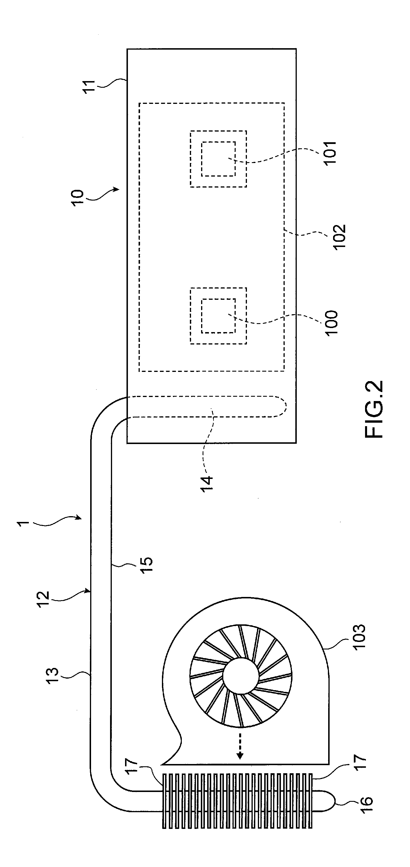
[0043] Hereinafter, a heat sink structure according to a first embodiment of the present disclosure will be described with reference to the accompanying drawings. As shown in FIGS. 1 and 2, the heat sink structure 1 according to the first embodiment includes a planar heat pipe 10, and a tubular heat pipe 12 thermally coupled to the planar heat pipe 10. In the heat sink structure 1, a planar container 11 of the planar heat pipe 10 and a tubular container 13 of the tubular heat pipe 12 come into direct contact with each other so that the planar heat pipe 10 and the tubular heat pipe 12 are thermally coupled to each other.
[0044] A plurality of heat generating elements (two heat generating elements, that is, a first heat generating element 100 and a second heat generating element 101 in FIG. 1) mounted on a substrate 102 are thermally coupled to the planar heat pipe 10. That is, the first heat generating element 100 and the second heat generating element 101 are thermally coupled to the same planar heat pipe 10. Accordingly, the first heat generating element 100 and the second heat generating element 101 are thermally coupled to each other through the planar heat pipe 10. The planar heat pipe 10 has portions to which the first heat generating element 100 and the second heat generating element 101 are thermally coupled, and the portions of the planar heat pipe 10 function as heat receiving portions of the planar heat pipe 10.
[0045] Placement of the planar heat pipe 10 on the first heat generating element 100 and the second heat generating element 101 allows the planar heat pipe 10 to be thermally coupled and fixed to the first heat generating element 100 and the second heat generating element 101.
[0046] In the heat sink structure 1, the planar heat pipe 10 may be placed on the first heat generating element 100 and the second heat generating element 101 so as to come into direct contact with the first heat generating element 100 and the second heat generating element 101. Alternatively, the planar heat pipe 10 may be placed on the first heat generating element 100 and the second heat generating element 101 with a thermally conductive grease not shown in the drawing inserted between the planar heat pipe 10 and the first heat generating element 100 and between the planar heat pipe 10 and the second heat generating element 101.
[0047] As shown in FIGS. 1 and 2, the planar heat pipe 10 has a peripheral edge portion which is separated at a predetermined distance from the portions of the planar heat pipe 10 to which the first heat generating element 100 and the second heat generating element 101 are thermally coupled. One end portion 14 of the tubular heat pipe 12 is thermally coupled to the peripheral edge portion of the planar heat pipe 10. In the heat sink structure 1, one tubular heat pipe 12 is thermally coupled to the peripheral edge portion of the planar heat pipe 10. A portion of the planar heat pipe 10 to which the one end portion 14 of the tubular heat pipe 12 is thermally coupled functions as a heat radiating portion of the planar heat pipe 10.
[0048] A method for thermally coupling the planar heat pipe 10 and the tubular heat pipe 12 to each other is not particularly limited. For example, fixing of the tubular container 13 of the tubular heat pipe 12 to the planar container 11 of the planar heat pipe 10 by soldering, by swaging or the like allows the planar heat pipe 10 and the tubular heat pipe 12 to be thermally coupled to each other.
[0049] The one end portion 14 of the tubular heat pipe 12 thermally coupled to the planar heat pipe 10 functions as a heat receiving portion of the tubular heat pipe 12. On the other hand, portions of the tubular heat pipe 12 other than the one end portion 14, that is, a center portion 15 and another end portion 16 do not come into contact with the planar heat pipe 10. Of the center portion 15 and the other end portion 16 of the tubular heat pipe 12, the other end portion 16 functions as a heat radiating portion of the tubular heat pipe 12. Unlike the planar heat pipe 10, a heat generating element is not coupled to the tubular heat pipe 12. As shown in FIGS. 1 and 2, the tubular heat pipe 12 may be bent, or may be used in a straight line shape. The tubular heat pipe 12 may be partially or wholly flattened so as to enhance thermal coupling performance.
[0050] In the heat sink structure 1, the whole tubular heat pipe 12 including the heat receiving portion is flattened. The one end portion 14 (heat receiving portion) of the tubular heat pipe 12 extends along the plane direction of the planar heat pipe 10. That is, the one end portion 14 of the tubular heat pipe 12 extends along the plane direction of the planar heat pipe 10 as viewed in a plan view. In the similar manner as the one end portion 14, the center portion 15 and the other end portion 16 of the tubular heat pipe 12 also extend along the plane direction of the planar heat pipe 10. Accordingly, the direction along which heat is transmitted in the tubular heat pipe 12 extends in the direction substantially parallel to the plane direction of the planar heat pipe 10.
[0051] In the heat sink structure 1, heat radiating fins 17 are attached to the other end portion 16 of the tubular heat pipe 12 (that is, the heat radiating portion of the tubular heat pipe 12) as a heat exchange unit. A blower fan 103 is disposed between the heat radiating fins 17 and the planar heat pipe 10. Cooling air from the blower fan 103 is supplied to the heat radiating fins 17.
[0052] In the heat sink structure 1, the plurality of heat radiating fins 17 are attached to the other end portion 16 of the tubular heat pipe 12 so that heat is smoothly discharged from the heat radiating portion of the tubular heat pipe 12 to an external environment. Further, the blower fan 103 is disposed between the heat radiating fins 17 and the planar heat pipe 10. Accordingly, with the operation of the blower fan 103, not only cooling air is supplied to the heat radiating fins 17 but also a flow of air is generated in the direction from the planar heat pipe 10 toward the heat radiating fins 17, and the flow of air functions also as cooling air for cooling the planar heat pipe 10.
[0053] The planar heat pipe 10 includes the planar container 11, a working fluid (not shown in the drawing) sealed in an inner space of the planar container 11, and a wick structure (not shown in the drawing) provided in the inner space of the planar container 11. The tubular heat pipe 12 includes the tubular container 13, a working fluid (not shown in the drawing) sealed in an inner space of the tubular container 13, and a wick structure (not shown in the drawing) provided in the inner space of the tubular container 13.
[0054] A material for forming the planar container 11 and the tubular container 13 may be copper, a copper alloy, aluminum, an aluminum alloy, nickel, a nickel alloy, stainless steel, titanium or the like, for example. The working fluid can be suitably selected according to compatibility with the material for forming the planar container 11 and the tubular container 13. The working fluid may be water, alternative fluorocarbons, fluorocarbon group such as Fluorinert, cyclopentane or the like, for example.
[0055] The wick structure may be a sintered body of metal powder such as copper powder, metal mesh, wires, grooves formed on inner surfaces of the planar container 11 and the tubular container 13 or the like.
[0056] The heat generating elements which are cooling targets are not particularly limited. The heat generating elements may be a central processing unit, a graphic chip (GPU, VGA), a memory, a capacitor, a power source and the like which are mounted on the substrate 102 (a circuit board incorporated in an electronic device, for example).
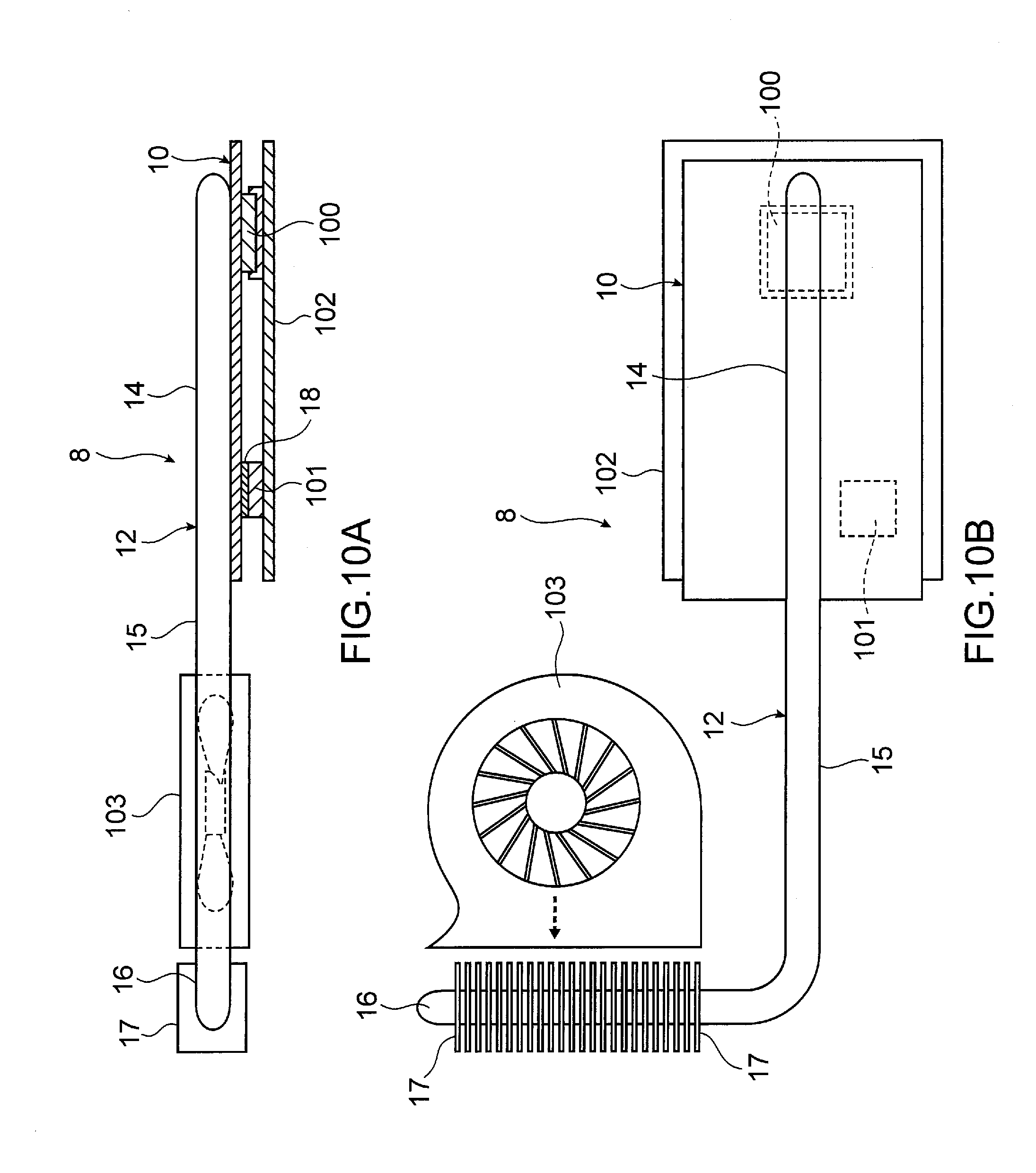
[0057] Next, a mechanism for a cooling effect of the heat sink structure 1 will be described. When the heat receiving portions of the planar heat pipe 10 receives heat from the first heat generating element 100 and the second heat generating element 101, the heat from the first heat generating element 100 and the second heat generating element 101 is transmitted from the heat receiving portions of the planar heat pipe 10 to the heat radiating portion of the planar heat pipe 10 coupled to the one end portion 14 of the tubular heat pipe 12. Planar portions of the planar heat pipe 10 other than the heat receiving portions of the planar heat pipe 10 function as the heat radiating portions of the planar heat pipe 10. A portion of the heat transmitted from the heat receiving portions to the heat radiating portion of the planar heat pipe 10 is transferred from the heat radiating portion of the planar heat pipe 10 to the one end portion 14 of the tubular heat pipe 12, that is, to the heat receiving portion of the tubular heat pipe 12. The heat transferred to the heat receiving portion of the tubular heat pipe 12 is transmitted to the other end portion 16 of the tubular heat pipe 12, that is, to the heat radiating portion of the tubular heat pipe 12. Then, the heat is discharged from the heat radiating portion of the tubular heat pipe 12 to an external environment through the heat radiating fins 17.
[0058] That is, the heat from the first heat generating element 100 and the second heat generating element 101 which the planar heat pipe 10 receives is transmitted to a portion which corresponds to the heat radiating fins 17 through the tubular heat pipe 12 thus being smoothly discharged to the external environment.
[0059] In the heat sink structure 1, the planar heat pipe is thermally coupled to the first heat generating element 100 and the second heat generating element 101 in a state of being placed on the first heat generating element 100 and the second heat generating element 101. Accordingly, blocking and narrowing of an inner space of the planar heat pipe can be reliably prevented and, therefore, the heat sink structure 1 exhibits excellent heat transmission characteristics thus reliably cooling the plurality of heat generating elements.
[0060] In the heat sink structure 1, the plurality of heat generating elements (the first heat generating element 100 and the second heat generating element 101) are thermally coupled to one planar heat pipe 10. Accordingly, the number of parts of the planar heat pipe 10 can be reduced and, at the same time, the heat sink structure 1 can be simplified. Further, in the heat sink structure 1, the plurality of heat generating elements are thermally coupled to one planar heat pipe 10, and the planar heat pipe 10 is thermally coupled to the tubular heat pipe 12 through which heat is transmitted to the portion where the heat radiating fins 17 are installed. Accordingly, even when the plurality of heat generating elements have different amounts of heat generation, the planar heat pipe 10 can make heating of the respective heat generating elements uniform thus making cooking of the respective heat generating elements uniform. Further, in the heat sink structure 1, the respective heat generating elements are thermally coupled to the planar heat pipe and hence, the heat sink structure 1 can even reliably cool heat generating elements installed in a narrow inner space, for example, in an inner space having a small size in the thickness direction.
[0061] Next, a heat sink structure according to a second embodiment of the present disclosure will be described with reference to the accompanying drawings. Constitutional elements identical to the constitutional elements of the heat sink structure according to the first embodiment of the present disclosure are given the same reference characters, and the description is made using the same reference characters.
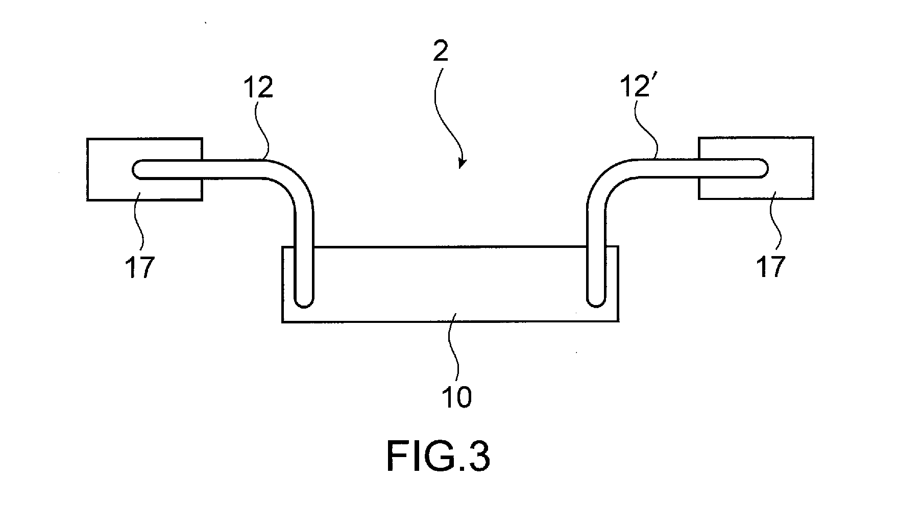
[0062] In the heat sink structure 1 according to the first embodiment, one tubular heat pipe 12 is thermally coupled to the peripheral edge portion of the planar heat pipe 10. However, in a heat sink structure 2 according to the second embodiment, as shown in FIG. 3, two tubular heat pipes 12, 12' are thermally coupled to a peripheral edge portion of the planar heat pipe 10.
[0063] In the heat sink structure 2, not only the tubular heat pipe 12 is thermally coupled to one predetermined portion of the peripheral edge portion of the planar heat pipe 10, but also another tubular heat pipe 12' is thermally coupled to the peripheral edge portion of the planar heat pipe 10 at the position on the side opposite to the tubular heat pipe 12. Heat radiating fins 17 are also provided on a heat radiating portion of the other tubular heat pipe 12' in the similar manner as the heat radiating portion of the tubular heat pipe 12.
[0064] Even when the two tubular heat pipes 12 are thermally coupled to the peripheral edge portion of the planar heat pipe 10, in the similar manner as the heat sink structure 1, the heat sink structure 2 can reliably cool the plurality of heat generating elements. That is, the number of tubular heat pipes 12 thermally coupled to the planar heat pipe 10 is not particularly limited, and may be single or plural. The number of tubular heat pipes 12 can be suitably selected depending on usage conditions including amount of heat generation by a heat generating element, the number of heat generating elements and the like.
[0065] Next, a heat sink structure according to a third embodiment of the present disclosure will be described with reference to the accompanying drawings. Constitutional elements identical to the constitutional elements of the heat sink structures according to the first and second embodiments of the present disclosure are given the same reference characters, and the description is made using the same reference characters.
[0066] In the heat sink structure 1 according to the first embodiment, the planar heat pipe 10 is thermally coupled to the respective heat generating elements (the first heat generating element 100 and the second heat generating element 101) such that the planar heat pipe 10 comes into direct contact with the respective heat generating elements, or comes into contact with the respective heat generating elements with the thermally conductive grease interposed therebetween. However, in a heat sink structure 3 according to the third embodiment, as shown in FIG. 4, a heat conductive member 18 is inserted between the planar heat pipe 10 and a heat generating element. In the heat sink structure 3, a third heat generating element 104 is mounted on the substrate 102 in addition to the first heat generating element 100 and the second heat generating element 101, that is, three heat generating elements are mounted on the substrate 102.
[0067] The above-mentioned aspect is particularly effective when the first heat generating element 100, the second heat generating element 101 and the third heat generating element 104 have different sizes in the height direction. That is, the heat conductive member 18 is inserted between each of the heat generating elements having a small size in the height direction (the second heat generating element 101 and the third heat generating element 104 in FIG. 4) and the planar heat pipe 10 thus causing the heat generating elements to have substantially the same height as the heat generating element having the largest size in the height direction (the first heat generating element 100 in FIG. 4). With such a configuration, the plurality of heat generating elements (the first heat generating element 100, the second heat generating element 101, and the third heat generating element 104) and the planar heat pipe 10 can be thermally coupled to each other without causing deformation such as deflection of the planar heat pipe 10.
[0068] The heat conductive member 18 may be formed of a thermally conductive sheet or the like, for example. In FIG. 4, a thermally conductive grease 19 is applied to a contact surface between the first heat generating element 100 and the planar heat pipe 10 so as to enhance thermal conductivity.
[0069] Next, a heat sink structure according to a fourth embodiment of the present disclosure will be described with reference to the accompanying drawings. Constitutional elements identical to the constitutional elements of the heat sink structures according to the first, second and third embodiments of the present disclosure are given the same reference characters, and the description is made using the same reference characters.
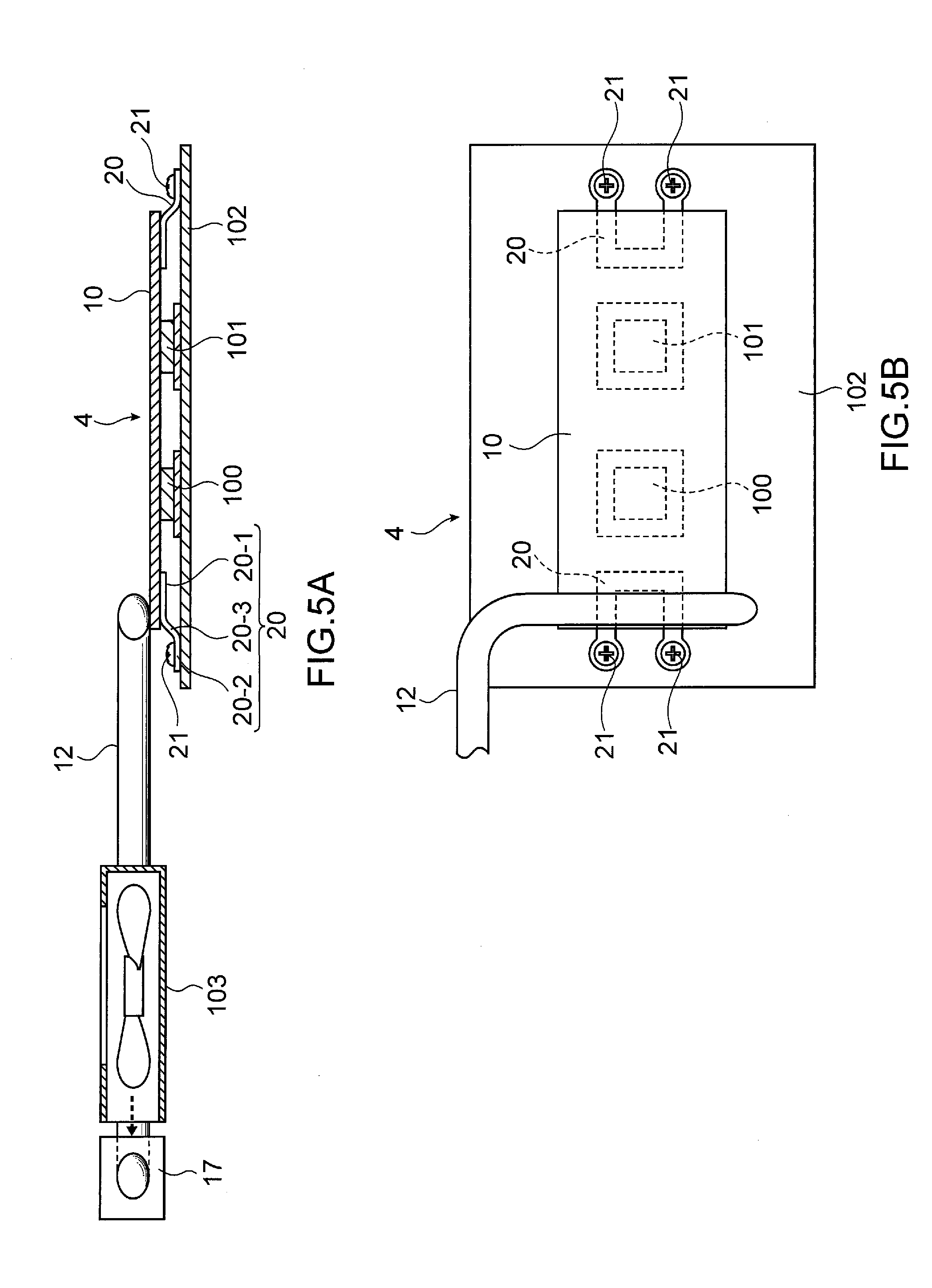
[0070] As shown in FIGS. 5A and 5B, in a heat sink structure 4 according to the fourth embodiment, biasing members 20 are also provided on a surface (back surface) of the planar heat pipe 10 on the side where heat generating elements are disposed. Providing the biasing members 20 to the back surface of the planar heat pipe 10 allows prevention of deformation such as deflection of the planar heat pipe 10, and also allows the planar heat pipe 10 to be biased in the direction toward the first heat generating element 100 and the second heat generating element 101. Accordingly, thermal coupling performance between the planar heat pipe 10 and the first heat generating element 100 and the second heat generating element 101 is enhanced. Further, the planar heat pipe 10 can be reliably fixed to the substrate 102. The tubular heat pipe 12 is attached to a surface (front surface) of the planar heat pipe 10 on the side where the heat generating elements are not disposed.
[0071] In the heat sink structure 4, two biasing members 20 are provided on the back surface of the planar heat pipe 10. The respective biasing members 20 are disposed at the peripheral edge portion of the planar heat pipe 10 so as to be oppositely positioned with each other. The respective heat generating elements (the first heat generating element 100 and the second heat generating element 101) are disposed between two biasing members 20. Accordingly, the planar heat pipe 10 in a state of being biased toward the substrate 102 side is thermally coupled to all heat generating elements. The biasing members 20 are fixed to the substrate 102 on which the first heat generating element 100 and the second heat generating element 101 are mounted.
[0072] Each biasing member 20 includes a first flat portion 20-1 attached to the back surface of the planar heat pipe 10 in a surface contact state, second flat portions 20-2 attached to the substrate 102 in a surface contact state, and coupling portions 20-3 which connect the first flat portion 20-1 and the second flat portions 20-2 to each other. The coupling portions 20-3 exhibit a biasing effect.
[0073] An attaching unit configured to attach the first flat portion 20-1 to the back surface of the planar heat pipe 10 is not particularly limited, and soldering or the like may be adopted, for example. A fixing unit configured to fix the second flat portions 20-2 to the substrate 102 is not particularly limited. In the heat sink structure 4, the second flat portions 20-2 are fixed to the substrate 102 by means of screws 21. That is, a through hole (not shown in the drawing) which allows the insertion of the screw 21 is formed in each second flat portion 20-2. Screw holes (not shown in the drawing) are formed in the substrate 102. Each screw 21 is inserted through the through hole, and is threadedly engaged with the screw hole so that the biasing members 20 are fixed to the substrate 102.
[0074] The biasing member 20 may be formed of a spring member such as a leaf spring or a coil made of metal, for example.
[0075] Next, a heat sink structure according to a fifth embodiment of the present disclosure will be described with reference to the accompanying drawings. Constitutional elements identical to the constitutional elements of the heat sink structures according to the first, second, third, and fourth embodiments of the present disclosure are given the same reference characters, and the description is made using the same reference characters.
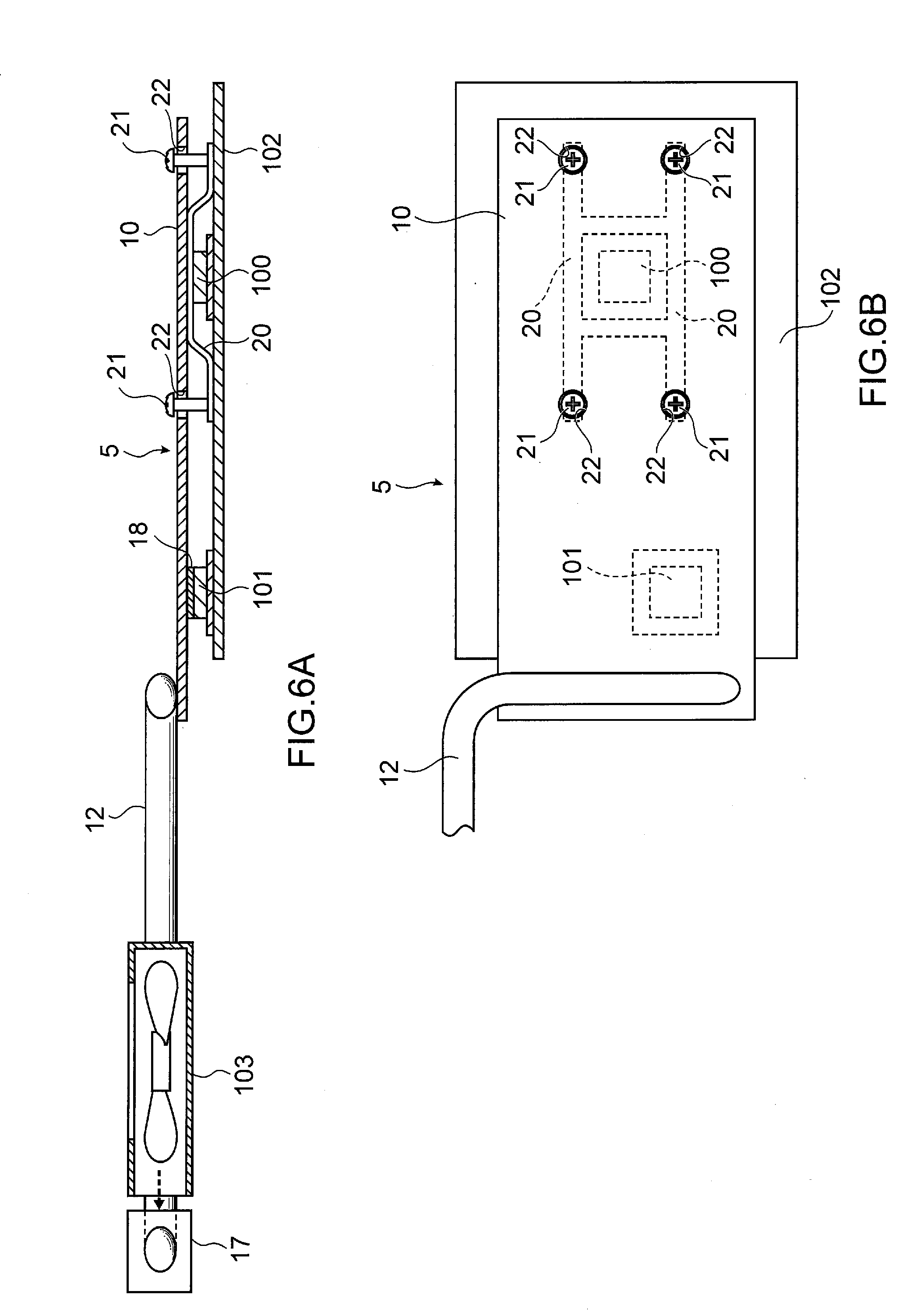
[0076] In the heat sink structure 4 according to the fourth embodiment, the planar heat pipe 10 in a state of being biased toward the substrate 102 side is thermally coupled to all heat generating elements. However, in a heat sink structure 5 according to the fifth embodiment, as shown in FIGS. 6A and 6B, the planar heat pipe 10 in a state of being biased toward the substrate 102 side is thermally coupled only to some heat generating elements (the first heat generating element 100 in FIG. 6) of a plurality of heat generating elements (two heat generating elements consisting of the first heat generating element 100 and the second heat generating element 101 in FIG. 6). Through holes 22 each of which allows the insertion of the screw 21 are formed in the planar heat pipe 10. Through holes (not shown in the drawing) each of which allows the insertion of the screw 21 are also formed in the biasing members 20. Screw holes (not shown in the drawing) are formed in the substrate 102. Each screw 21 is inserted through the through hole 22 formed in the planar heat pipe 10 and the through hole formed in the biasing member 20, and the screw 21 is threadedly engaged with the screw hole formed in the substrate 102. With such operations, the planar heat pipe 10 and the biasing members 20 are fixed to the substrate 102.
[0077] As shown in FIG. 6B, in the heat sink structure 5, the first heat generating element 100 is disposed between the two biasing members 20, but the second heat generating element 101 is not disposed between the two biasing members 20. A portion of the planar heat pipe 10 which is not biased in the direction toward the substrate 102 is thermally coupled to the second heat generating element 101. The heat conductive member 18 formed of a thermally conductive sheet or the like is inserted between the second heat generating element 101 and the planar heat pipe 10. The planar heat pipe 10 is biased also in the direction toward the first heat generating element 100 due to a cushioning function of the heat conductive member 18.
[0078] Also in the above-mentioned aspect, deformation such as deflection of the planar heat pipe 10 can be prevented, and thermal coupling performance between the planar heat pipe 10 and the first heat generating element 100 can be enhanced. Further, the planar heat pipe 10 can be reliably fixed to the substrate 102.
[0079] Next, other embodiments of the present disclosure will be described. In the above-mentioned first to fifth embodiments, the heat radiating fins are provided on the heat radiating portion of the tubular heat pipe as the heat exchange unit. However, the heat exchange unit may not be provided depending on usage conditions. In the above-mentioned first to fifth embodiments, the blower fan is installed in the vicinity of the heat radiating fins. However, the blower fan may not be installed depending on usage conditions.
[0080] In the heat sink structures according to the first and fourth embodiments, the planar heat pipe is placed on the respective heat generating elements such that the planar heat pipe comes into direct contact with the respective heat generating elements, or comes into contact with the respective heat generating elements with the thermally conductive grease interposed therebetween. However, a heat conductive member may be disposed between each heat generating element and the planar heat pipe.
[0081] The above-mentioned heat sink structure of the present disclosure has excellent heat transmission characteristics, and can make cooling of the plurality of heat generating elements installed in a narrowed inner space uniform with a simple configuration. Accordingly, for example, the heat sink structure of the present disclosure has a high utility in the field of cooling a plurality of heat generating elements installed in a space having a small size in the thickness direction.
[0082] Hereinafter, a heat sink structure according to a sixth embodiment of the present disclosure will be described with reference to the accompanying drawings. As shown in FIGS. 7 and 8, a heat sink structure 6 according to the sixth embodiment includes the planar heat pipe 10 and the tubular heat pipe 12 thermally coupled to the planar heat pipe 10. In the heat sink structure 6, the planar container 11 of the planar heat pipe 10 and the tubular container 13 of the tubular heat pipe 12 come into direct contact with each other so that the planar heat pipe 10 and the tubular heat pipe 12 are thermally coupled to each other.
[0083] In the heat sink structure 6, the tubular heat pipe 12 is disposed on the side of the planar heat pipe 10 closer to heat generating elements. The first heat generating element 100 mounted on the substrate 102 is thermally coupled to the tubular heat pipe 12, and the second heat generating element 101 mounted on the substrate 102 is thermally coupled to the planar heat pipe 10. Accordingly, the first heat generating element 100 is thermally coupled to the planar heat pipe 10 through the tubular heat pipe 12, and the second heat generating element 101 is thermally coupled to the tubular heat pipe 12 through the planar heat pipe 10. Accordingly, the planar heat pipe 10 has a function as a soaking plate.
[0084] The heat sink structure 6 may be configured such that the tubular heat pipe 12 comes into direct contact with the first heat generating element 100 thus being thermally coupled to the first heat generating element 100, and the planar heat pipe 10 comes into direct contact with the second heat generating element 101 thus being thermally coupled to the second heat generating element 101. Alternatively, a thermally conductive grease not shown in the drawing may be inserted between the tubular heat pipe 12 and the first heat generating element 100 and between the planar heat pipe 10 and the second heat generating element 101 thus thermally coupling the tubular heat pipe 12 and the first heat generating element 100 to each other and the planar heat pipe 10 and the second heat generating element 101 to each other.
[0085] As shown in FIGS. 7 and 8, a one end portion 14 of the tubular heat pipe 12 is thermally coupled to the planar heat pipe 10, and the first heat generating element 100 is thermally coupled to the one end portion 14 of the tubular heat pipe 12. That is, as shown in FIG. 8, the first heat generating element 100 is thermally coupled to the position where the planar heat pipe 10 and the tubular heat pipe 12 overlap with each other as viewed in a plan view. On the other hand, the second heat generating element 101 is thermally coupled to the planar heat pipe 10 at the position where the planar heat pipe 10 does not overlap with the tubular heat pipe 12 as viewed in a plan view. In the heat sink structure 6, one tubular heat pipe 12 is thermally coupled to the planar heat pipe 10.
[0086] A method for thermally coupling the planar heat pipe 10 and the tubular heat pipe 12 to each other is not particularly limited. For example, fixing of the tubular container 13 of the tubular heat pipe 12 to the planar container 11 of the planar heat pipe 10 by soldering, by swaging or the like allows the planar heat pipe 10 and the tubular heat pipe 12 to be thermally coupled to each other.
[0087] The one end portion 14 of the tubular heat pipe 12 thermally coupled to the planar heat pipe 10 and to the first heat generating element 100 functions as a heat receiving portion of the tubular heat pipe 12. On the other hand, portions of the tubular heat pipe 12 other than the one end portion 14, that is, the center portion 15 and the other end portion 16 do not come into contact with the planar heat pipe 10. Of the center portion 15 and the other end portion 16 of the tubular heat pipe 12, the other end portion 16 functions as a heat radiating portion of the tubular heat pipe 12. As shown in FIGS. 7 and 8, the tubular heat pipe 12 may be bent, or may be used in a straight line shape. The tubular heat pipe 12 may be partially or wholly flattened so as to enhance thermal coupling performance.
[0088] In the heat sink structure 6, the whole tubular heat pipe 12 including the heat receiving portion is flattened. The one end portion 14 (heat receiving portion) of the tubular heat pipe 12 extends along the plane direction of the planar heat pipe 10. That is, the one end portion 14 of the tubular heat pipe 12 extends along the plane direction of the planar heat pipe 10 as viewed in a plan view. In the similar manner as the one end portion 14, the center portion 15 and the other end portion 16 of the tubular heat pipe 12 also extend along the plane direction of the planar heat pipe 10. Accordingly, the direction along which heat is transmitted in the tubular heat pipe 12 extends in the direction substantially parallel to the plane direction of the planar heat pipe 10.
[0089] In the heat sink structure 6, the heat radiating fins 17 are attached to the other end portion 16 of the tubular heat pipe 12 (that is, the heat radiating portion of the tubular heat pipe 12) as a heat exchange unit. The blower fan 103 is disposed between the heat radiating fins 17 and the planar heat pipe 10. Cooling air from the blower fan 103 is supplied to the heat radiating fins 17.
[0090] In the heat sink structure 6, the plurality of heat radiating fins 17 are attached to the other end portion 16 of the tubular heat pipe 12 so that heat is smoothly discharged from the heat radiating portion of the tubular heat pipe 12 to an external environment. A position where the blower fan 103 is installed is not particularly limited. However, by disposing the blower fan 103 between the heat radiating fins 17 and the planar heat pipe 10, with the operation of the blower fan 103, not only cooling air is supplied to the heat radiating fins 17 but also a flow of air is generated in the direction from the planar heat pipe 10 toward the heat radiating fins 17, and the flow of air functions also as cooling air for cooling the planar heat pipe 10.
[0091] The planar heat pipe 10 includes the planar container 11, a working fluid (not shown in the drawing) sealed in the inner space of the planar container 11, and a wick structure (not shown in the drawing) provided in the inner space of the planar container 11. The tubular heat pipe 12 includes the tubular container 13, a working fluid (not shown in the drawing) sealed in the inner space of the tubular container 13, and a wick structure (not shown in the drawing) provided in the inner space of the tubular container 13.
[0092] A material for forming the planar container 11 and the tubular container 13 may be copper, a copper alloy, aluminum, an aluminum alloy, nickel, a nickel alloy, stainless steel, titanium or the like, for example. The working fluid can be suitably selected according to compatibility with the material for forming the planar container 11 and the tubular container 13. The working fluid may be water, alternative fluorocarbons, fluorocarbon group such as Fluorinert, cyclopentane or the like, for example.
[0093] The wick structure may be a sintered body of metal powder such as copper powder, metal mesh, wires, grooves formed on inner surfaces of the planar container 11 and the tubular container 13 or the like.
[0094] The heat generating elements which are cooling targets are not particularly limited. The heat generating elements may be a central processing unit, a graphic chip (GPU, VGA), a memory, a capacitor, a power source and the like which are mounted on the substrate 102 (a circuit board incorporated in an electronic device, for example).
[0095] Next, a mechanism for a cooling effect of the heat sink structure 6 will be described. When the one end portion 14 (heat receiving portion) of the tubular heat pipe 12 receives heat from the first heat generating element 100, the heat transferred from the first heat generating element 100 to the heat receiving portion of the tubular heat pipe 12 is transmitted to the other end portion 16 of the tubular heat pipe 12, that is, to the heat radiating portion of the tubular heat pipe 12. Then, the heat is discharged from the heat radiating portion of the tubular heat pipe 12 to an external environment through the heat radiating fins 17.
[0096] A portion of the heat transferred to the heat receiving portion of the tubular heat pipe 12 is not transmitted to the heat radiating portion of the tubular heat pipe 12, but is transferred to the planar heat pipe 10 thermally coupled to the one end portion 14 of the tubular heat pipe 12. The heat transferred from the heat receiving portion of the tubular heat pipe 12 to the planar heat pipe 10 is discharged from the planar heat pipe 10 while diffusing along a planar surface of the planar heat pipe 10. On the other hand, when the planar heat pipe 10 receives heat from the second heat generating element 101, in the similar manner as the heat transferred from the first heat generating element 100, heat transferred from the second heat generating element 101 to the planar heat pipe 10 is discharged from the planar heat pipe 10 while diffusing along the planar surface of the planar heat pipe 10.
[0097] Further, depending on an amount of heat generation by the second heat generating element 101, heat transferred from the second heat generating element 101 to the planar heat pipe 10 diffuses along the planar surface of the planar heat pipe 10, and a portion of the heat is transmitted to the one end portion 14 of the tubular heat pipe 12, and is discharged to an external environment from the heat radiating portion of the tubular heat pipe 12 through the heat radiating fins 17. Accordingly, the planar heat pipe 10 has a function as a soaking plate.
[0098] That is, the heat from the first heat generating element 100 and the second heat generating element 101 which the heat sink structure 6 receives is transmitted to a portion which corresponds to the heat radiating fins 17 through the tubular heat pipe 12 thus being smoothly discharged to the external environment. Further, the heat diffuses along the planar surface of the planar heat pipe 10 thus being discharged also from the planar heat pipe 10.
[0099] As described above, in the heat sink structure 6, the planar heat pipe 10 and the tubular heat pipe 12 are thermally coupled to each other. Accordingly, the tubular heat pipe 12 exhibits a heat transmission function in a state where heat from the first heat generating element 100 and heat from the second heat generating element 101 diffuse on the surface of the planar heat pipe 10 thus increasing a heat dissipation area. Further, at least some heat generating elements (first heat generating element 100) of the plurality of heat generating elements (the first heat generating element 100 and the second heat generating element 101) are thermally coupled to the position where the planar heat pipe 10 and the tubular heat pipe 12 overlap with each other. Accordingly, heat is smoothly transferred from the first heat generating element 100 to the tubular heat pipe 12. Therefore, the heat sink structure 6 has excellent heat transmission characteristics and functions as a soaking plate thus exhibiting excellent cooling performance with respect to the heat generating elements.
[0100] Assume a case where the heat sink structure 6 cools a plurality of heat generating elements (the first heat generating element 100 and the second heat generating element 101) which have different amounts of heat generation. In such a case, in the heat sink structure 6, a heat generating element having a relatively small amount of heat generation (the second heat generating element 101, for example) can be cooled by the planar heat pipe 10 having a function as a soaking plate. Accordingly, the heat transmission amount of the tubular heat pipe 12 can be reduced by a corresponding amount.
[0101] In the heat sink structure 6, the planar heat pipe 10 is used, and the number of heat generating elements to be thermally coupled is not particularly limited. Accordingly, the heat sink structure 6 can exhibit excellent cooling performance with respect to heat generating elements installed in a narrowed inner space with a simple configuration.
[0102] In the heat sink structure 6, the tubular heat pipe 12 is disposed on the side of the planar heat pipe 10 closer to the heat generating elements (the first heat generating element 100 and the second heat generating element 101) (on the side closer to the substrate 102). Accordingly, heat from the heat generating element (the first heat generating element 100 in FIGS. 7 and 8) is smoothly transferred to the tubular heat pipe 12. Further, heat transferred from the respective heat generating elements (the first heat generating element 100 and the second heat generating element 101) diffuses on the surface of the planar heat pipe 10 due to a function of the planar heat pipe 10 as a soaking plate thus increasing a heat dissipation area. Accordingly, a heat transmission amount of the tubular heat pipe 12 can be reduced and, therefore, the tubular heat pipe 12 can be flattened and reduced in diameter. As described above, the tubular heat pipe 12 can be flattened and reduced in diameter and hence, the heat sink structure 6 can be further miniaturized.
[0103] Next, a heat sink structure according to a seventh embodiment of the present disclosure will be described with reference to the accompanying drawings. Constitutional elements identical to the constitutional elements of the heat sink structure according to the sixth embodiment of the present disclosure are given the same reference characters, and the description is made using the same reference characters.
[0104] In the heat sink structure 6 according to the sixth embodiment, the first heat generating element 100 mounted on the substrate 102 is coupled to the tubular heat pipe 12, and the second heat generating element 101 mounted on the substrate 102 is coupled to the planar heat pipe 10. However, in a heat sink structure 7 according to the seventh embodiment, as shown in FIGS. 9A and 9B, a heat generating element is not coupled to the planar heat pipe 10.
[0105] That is, as shown in FIG. 9, the first heat generating element 100 is thermally coupled to the position where the planar heat pipe 10 and the tubular heat pipe 12 overlap with each other as viewed in a plan view. On the other hand, a heat generating element is not coupled to the position where the tubular heat pipe 12 and the planar heat pipe 10 do not overlap with each other as viewed in a plan view.
[0106] Also in the heat sink structure 7, the planar heat pipe 10 and the tubular heat pipe 12 are thermally coupled to each other. Accordingly, the tubular heat pipe 12 exhibits a heat transmission function in a state where, due to the provision of the planar heat pipe 10, heat from the first heat generating element 100 diffuses along the planar surface of the planar heat pipe 10 thus increasing a heat dissipation area. Further, the heat generating element (the first heat generating element 100) is thermally coupled to the position where the planar heat pipe 10 and the tubular heat pipe 12 overlap with each other. Accordingly, heat is smoothly transferred from the first heat generating element 100 to the tubular heat pipe 12. Therefore, in the similar manner as the heat sink structure 6, the heat sink structure 7 also has excellent heat transmission characteristics and functions as a soaking plate thus exhibiting excellent cooling performance with respect to the heat generating elements.
[0107] Next, a heat sink structure according to an eighth embodiment of the present disclosure will be described with reference to the accompanying drawings. Constitutional elements identical to the constitutional elements of the heat sink structure according to the sixth and seventh embodiments of the present disclosure are given the same reference characters, and the description is made using the same reference characters.
[0108] In the heat sink structure 6 according to the sixth embodiment, the tubular heat pipe 12 is disposed on the side of the planar heat pipe 10 closer to the heat generating elements. However, in a heat sink structure 8 according to the eighth embodiment, as shown in FIGS. 10A and 10B, the planar heat pipe 10 is disposed on the side of the tubular heat pipe 12 closer to the heat generating elements.
[0109] Heat generating elements (a plurality of heat generating elements, that is, the first heat generating element 100 and the second heat generating element 101 in FIG. 10) mounted on the substrate 102 are coupled to the planar heat pipe 10. On the other hand, a heat generating element is not coupled to the tubular heat pipe 12. Accordingly, both heat generating elements, that is, both the first heat generating element 100 and the second heat generating element 101 are thermally coupled to the tubular heat pipe 12 through the planar heat pipe 10. Accordingly, the planar heat pipe 10 has a function as a soaking plate.
[0110] As shown in FIG. 10B, some heat generating elements (the first heat generating element 100 in FIG. 10B) of the plurality of heat generating elements are thermally coupled to the planar heat pipe 10 at the position where the planar heat pipe 10 and the tubular heat pipe 12 overlap with each other as viewed in a plan view. On the other hand, some of remaining heat generating elements (the second heat generating element 101 in FIG. 10B) is thermally coupled to the planar heat pipe 10 at the position which does not overlap with the tubular heat pipe 12 as viewed in a plan view.
[0111] As shown in FIG. 10A, in the heat sink structure 8, the first heat generating element 100 is thermally coupled to the planar heat pipe 10 such that the first heat generating element 100 comes into direct contact with the planar heat pipe 10, or comes into contact with the planar heat pipe 10 with a thermally conductive grease (not shown in the drawing) interposed therebetween. On the other hand, the heat conductive member 18 formed of a thermally conductive sheet or the like is inserted between the planar heat pipe 10 and the second heat generating element 101 so that the second heat generating element 101 is thermally coupled to the planar heat pipe 10 through the heat conductive member 18.
[0112] Assume a case where heat generating elements having different sizes in the height direction are thermally coupled to the heat sink structure 8 as described above. In such a case, the heat conductive member 18 is inserted between the heat generating element having a small size in the height direction (the second heat generating element 101 in FIG. 10A) and the planar heat pipe 10. With such a configuration, an increase in thermal resistance can be prevented, and height adjustment can be performed between the heat generating elements having different sizes in the height direction. Accordingly, deformation such as deflection of the planar heat pipe 10 can be prevented and hence, the inner space of the planar heat pipe 10 can be maintained and, as a result, the lowering of cooling performance of the heat sink structure 8 can be prevented.
[0113] Next, a mechanism for a cooling effect of the heat sink structure 8 will be described. When the planar heat pipe 10 receives heat from the first heat generating element 100 and heat from the second heat generating element 101, both the heat from the first heat generating element 100 and the heat from the second heat generating element 101 are discharged from the planar heat pipe 10 while diffusing on the planar heat pipe 10 along the planar surface of the planar heat pipe 10. Further, the tubular heat pipe 12 is provided at the position where the tubular heat pipe 12 overlaps with the first heat generating element 100 as viewed in a plan view, and the one end portion 14 (heat receiving portion) of the tubular heat pipe 12 comes into direct contact with the planar heat pipe 10. Accordingly, heat which is not discharged from the planar heat pipe 10 is transferred to the heat receiving portion of the tubular heat pipe 12. The heat transferred to the heat receiving portion of the tubular heat pipe 12 is transmitted from the heat receiving portion of the tubular heat pipe 12 to the other end portion 16 (heat radiating portion) of the tubular heat pipe 12, and is discharged to an external environment from the heat radiating fins 17 provided on the heat radiating portion. Accordingly, the tubular heat pipe 12 has a function of transmitting the heat which is not discharged from the planar heat pipe 10 to a portion which corresponds to the heat radiating fins.
[0114] The planar heat pipe 10 is disposed on the side of the tubular heat pipe 12 closer to the heat generating elements (the first heat generating element 100 and the second heat generating element 101) and hence, due to a function of the planar heat pipe 10 as a soaking plate, heat from the heat generating elements first diffuses along the planar surface of the planar heat pipe 10 and, then, is transferred to the tubular heat pipe 12. Accordingly, the generation of a hot spot in the planar heat pipe 10 can be prevented. As described above, in the heat sink structure 8, the generation of a hot spot in the planar heat pipe 10 can be prevented and hence, the heat sink structure 8 can exhibit excellent cooling performance with respect to the heat generating elements. Further, the planar heat pipe 10 can cover the whole heat generating elements (the first heat generating element 100 and the second heat generating element 101) coupled to the planar heat pipe 10 as viewed in a plan view and hence, heat transfer performance from the heat generating element to the heat sink structure 8 is enhanced.
[0115] Next, other embodiments of the present disclosure will be described. In the above-mentioned sixth to eighth embodiments, one tubular heat pipe is installed. However, the number of tubular heat pipes to be installed is not particularly limited. A plurality of tubular heat pipes may be installed depending on usage conditions of the heat sink structure.
[0116] For example, in the heat sink structure 6 according to the sixth embodiment, one tubular heat pipe 12 is thermally coupled to the first heat generating element 100 mounted on the substrate 102. However, as shown in FIG. 11, in a heat sink structure 9 according to a ninth embodiment, a plurality of (two in FIG. 11) tubular heat pipes 12, 12' may be thermally coupled to the first heat generating element 100 mounted on the substrate 102.
[0117] In the heat sink structure 9, two tubular heat pipes 12, 12' are thermally coupled to a position which overlaps with the first heat generating element 100 as viewed in a plan view. In the heat sink structure 9, portions of the two tubular heat pipes 12, 12' which overlap with the first heat generating element 100 as viewed in a plan view are disposed parallel to each other. Portions of the two tubular heat pipes 12, 12' which do not overlap with the planar heat pipe 10 as viewed in a plan view are disposed such that the one tubular heat pipe 12 and the other tubular heat pipe 12' are disposed substantially symmetrically with respect to a center line of the planar heat pipe 10.
[0118] The plurality of tubular heat pipes 12, 12' are thermally coupled to the first heat generating element 100 thus reliably cooling the first heat generating element 100 even when the first heat generating element 100 has a large amount of heat generation.
[0119] The number of heat generating elements to be thermally coupled to the position where the planar heat pipe and the tubular heat pipe overlap with each other as viewed in a plan view is not particularly limited. In the above-mentioned sixth to eighth embodiments, one heat generating element is thermally coupled to the position. However, a plurality of heat generating elements may be thermally coupled to the position.
[0120] In the above-mentioned sixth to eighth embodiments, the heat radiating fins are provided on the heat radiating portion of the tubular heat pipe as the heat exchange unit. However, the heat exchange unit may not be provided depending on usage conditions. In the above-mentioned sixth to eighth embodiments, the blower fan is installed in the vicinity of the heat radiating fins. However, the blower fan may not be installed depending on usage conditions. Further, a thermally conductive grease may be applied between the heat generating element and the planar heat pipe or the tubular heat pipe so as to enhance thermal coupling performance when necessary.
[0121] The above-mentioned heat sink structure of the present disclosure has excellent heat transmission characteristics and functions as a soaking plate with respect to the heat generating elements installed in a narrowed inner space with a simple configuration thus exhibiting excellent cooling performance. Accordingly, for example, the heat sink structure of the present disclosure has a high utility in the field of cooling heat generating elements mounted on a substrate.
* * * * *
D00000
D00001
D00002
D00003
D00004
D00005
D00006
D00007
D00008
D00009
D00010
D00011
XML
uspto.report is an independent third-party trademark research tool that is not affiliated, endorsed, or sponsored by the United States Patent and Trademark Office (USPTO) or any other governmental organization. The information provided by uspto.report is based on publicly available data at the time of writing and is intended for informational purposes only.
While we strive to provide accurate and up-to-date information, we do not guarantee the accuracy, completeness, reliability, or suitability of the information displayed on this site. The use of this site is at your own risk. Any reliance you place on such information is therefore strictly at your own risk.
All official trademark data, including owner information, should be verified by visiting the official USPTO website at www.uspto.gov. This site is not intended to replace professional legal advice and should not be used as a substitute for consulting with a legal professional who is knowledgeable about trademark law.