Dual Fuel Selectable Apparatus
Deng; David
U.S. patent application number 16/238414 was filed with the patent office on 2019-05-09 for dual fuel selectable apparatus. The applicant listed for this patent is David Deng. Invention is credited to David Deng.
| Application Number | 20190137097 16/238414 |
| Document ID | / |
| Family ID | 66326344 |
| Filed Date | 2019-05-09 |


View All Diagrams
| United States Patent Application | 20190137097 |
| Kind Code | A1 |
| Deng; David | May 9, 2019 |
DUAL FUEL SELECTABLE APPARATUS
Abstract
A heater assembly can be used with a gas appliance. The gas appliance can be a dual fuel appliance for use with one of a first fuel type or a second fuel type different than the first. The heater assembly can include a pressure sensor and a plurality of valves operable by a control module dependent upon a detected fuel pressure. The valves may be solenoid valves that can reduce the available fuel delivery paths to limit fuel delivery to a burner when a higher pressure, such as detection of LP gas, is detected.
| Inventors: | Deng; David; (Diamond Bar, CA) | ||||||||||
| Applicant: |
|
||||||||||
|---|---|---|---|---|---|---|---|---|---|---|---|
| Family ID: | 66326344 | ||||||||||
| Appl. No.: | 16/238414 | ||||||||||
| Filed: | January 2, 2019 |
Related U.S. Patent Documents
| Application Number | Filing Date | Patent Number | ||
|---|---|---|---|---|
| 15175799 | Jun 7, 2016 | 10222057 | ||
| 16238414 | ||||
| 13791652 | Mar 8, 2013 | 9739389 | ||
| 15175799 | ||||
| 13791667 | Mar 8, 2013 | 9523497 | ||
| 13791652 | ||||
| 13310664 | Dec 2, 2011 | 8985094 | ||
| 13791667 | ||||
| 62322746 | Apr 14, 2016 | |||
| 62216807 | Sep 10, 2015 | |||
| 61748044 | Dec 31, 2012 | |||
| 61748052 | Dec 31, 2012 | |||
| 61473714 | Apr 8, 2011 | |||
| Current U.S. Class: | 1/1 |
| Current CPC Class: | F23N 2237/08 20200101; F23C 1/00 20130101; F23D 17/00 20130101; F23N 2235/24 20200101; F23N 1/002 20130101; F23K 2900/05002 20130101; F23D 2900/05002 20130101; F23D 2900/14641 20130101; F23N 2235/20 20200101; F23D 2900/00017 20130101; F23N 2235/18 20200101; F23D 14/10 20130101; F23D 23/00 20130101; F23K 2400/201 20200501; F23K 5/005 20130101; F23N 2225/04 20200101; F23K 5/007 20130101 |
| International Class: | F23D 14/10 20060101 F23D014/10; F23C 1/00 20060101 F23C001/00; F23D 23/00 20060101 F23D023/00; F23K 5/00 20060101 F23K005/00 |
Foreign Application Data
| Date | Code | Application Number |
|---|---|---|
| Oct 20, 2011 | CN | 201120401676.3 |
| Jul 2, 2012 | CN | 201210224414.3 |
| Jul 2, 2012 | CN | 201220314766.3 |
| Jul 2, 2012 | CN | 201220315268.0 |
| Sep 13, 2012 | CN | 201210336108.9 |
| Sep 13, 2012 | CN | 201220463373.9 |
| Jul 2, 2015 | CN | 201210223977.0 |
| Dec 23, 2015 | CN | 201510977056.7 |
Claims
1. A dual fuel heating apparatus comprising: a regulator receiving a gas fuel flow; a first regulator fuel path and a second regulator fuel path through the regulator; a pressure sensor configured to detect a pressure of the gas fuel flow in the regulator; a control module in communication with the pressure sensor; and a regulator valve operable to open or close the second regulator flow path depending on a pressure detected by the pressure sensor.
2. The dual fuel heating apparatus of claim 1, wherein the gas fuel flow is one of a natural gas fuel flow and a propane gas fuel flow.
3. The dual fuel heating apparatus of claim 2, wherein the pressure sensor is a normally open switch, closing when a predetermined pressure is reached.
4. The dual fuel heating apparatus of claim 2, wherein the pressure sensor determines whether the pressure of the gas fuel flow is greater than a predetermined pressure, wherein the predetermined pressure is a pressure greater than a pressure of the natural gas fuel flow and less than or equal to a pressure of the propane gas fuel flow.
5. The dual fuel heating apparatus of claim 3, wherein the regulator valve is a pick and hold solenoid valve.
6. The dual fuel heating apparatus of claim 5, wherein the control module sends a positive output voltage pulse when the pressure exceeds the predetermined pressure to move the solenoid valve from a first position, with the second regulator flow path closed, to a second position, with the second regulator flow path open.
7. The dual fuel heating apparatus of claim 5, further comprising a reset button, wherein the reset button, when depressed, is operable to cause the control module to send a negative output voltage pulse to move the solenoid valve into the first position, with the second regulator flow path closed.
8. The dual fuel heating apparatus of claim 1, further comprising: one or more dual fuel gas valves receiving fuel from the regulator, each of the one or more dual fuel gas valves having a first gas valve flow path and a second gas valve flow path for delivering fuel from the regulator to one or more burners; and a burner valve operable to open or close the second gas valve flow path depending on a pressure detected by the pressure sensor.
9. The dual fuel heating apparatus of claim 8, wherein: the gas fuel flow is one of a natural gas fuel flow and a propane gas fuel flow; and the pressure sensor determines whether the pressure of the gas fuel flow is greater than a predetermined pressure, wherein the predetermined pressure is a pressure greater than a pressure of the natural gas fuel flow and less than or equal to a pressure of the propane gas fuel flow.
10. The dual fuel heating apparatus of claim 9, wherein the control module sends a positive output voltage pulse when the pressure exceeds the predetermined pressure to move the burner valve from a first position, with the second gas valve flow path open, to a second position, with the second gas valve flow path closed.
11. The dual fuel heating apparatus of claim 10, further comprising a reset button, wherein the reset button, when depressed, is operable to cause the control module to send a negative output voltage pulse to move the burner valve into the first position, with the second gas valve flow path open.
12. A dual fuel heating apparatus comprising: a regulator receiving a gas fuel flow; a pressure sensor configured to detect a pressure of the gas fuel flow in the regulator; a control module in communication with the pressure sensor; one or more dual fuel gas valves receiving fuel from the regulator, each of the one or more dual fuel gas valves having a first gas valve flow path and a second gas valve flow path for delivering fuel from the regulator to one or more burners; and a burner valve operable to open or close the second gas valve flow path depending on a pressure detected by the pressure sensor.
13. The dual fuel heating apparatus of claim 12, wherein: the gas fuel flow is one of a natural gas fuel flow and a propane gas fuel flow; and the pressure sensor determines whether the pressure of the gas fuel flow is greater than a predetermined pressure, wherein the predetermined pressure is a pressure greater than a pressure of the natural gas fuel flow and less than or equal to a pressure of the propane gas fuel flow.
14. The dual fuel heating apparatus of claim 13, wherein the control module sends a positive output voltage pulse when the pressure exceeds the predetermined pressure to move the burner valve from a first position, with the second gas valve flow path open, to a second position, with the second gas valve flow path closed.
15. The dual fuel heating apparatus of claim 14, further comprising a reset button, wherein the reset button, when depressed, is operable to cause the control module to send a negative output voltage pulse to move the burner valve into the first position, with the second gas valve flow path open.
16. The dual fuel heating apparatus of claim 15, wherein the regulator has a first regulator fuel path and a second regulator fuel path through the regulator to pass a fuel flow therethrough, wherein the dual fuel heating apparatus further comprises a regulator valve operable to open or close the second regulator flow path depending on a pressure detected by the pressure sensor.
17. A dual fuel heating apparatus comprising: a regulator receiving a gas fuel flow of either a natural gas fuel flow or a propane gas fuel flow; a first regulator fuel path and a second regulator fuel path for delivering fuel through the regulator; a pressure sensor configured to detect a pressure of the gas fuel flow in the regulator; a control module in communication with the pressure sensor; a regulator valve operable to open the second regulator flow path when the pressure exceeds a predetermined pressure; one or more dual fuel gas valves receiving fuel from the regulator, each of the one or more dual fuel gas valves having a first gas valve flow path and a second gas valve flow path for delivering fuel from the regulator to one or more burners; and a burner valve operable to close the second gas valve flow path when the pressure exceeds the predetermined pressure.
18. The dual fuel heating apparatus of claim 17, wherein the predetermined pressure is a pressure greater than a pressure of the natural gas fuel flow and less than or equal to a pressure of the propane gas fuel flow.
19. The dual fuel heating apparatus of claim 17, wherein the control module sends a positive output voltage pulse when the pressure exceeds the predetermined pressure, the positive output voltage pulse moving the burner valve from a first position, with the second gas valve flow path open, to a second position, with the second gas valve flow path closed, and the positive output voltage pulse moving the regulator valve from a first position, with the second regulator flow path closed, to a second position, with the second regulator flow path open.
20. The dual fuel heating apparatus of claim 19, further comprising a reset button, wherein the reset button, when depressed, is operable to cause the control module to send a negative output voltage pulse to move the burner valve into the first position, with the second gas valve flow path open.
Description
CROSS-REFERENCE TO RELATED APPLICATIONS
[0001] This application is a continuation-in-part of U.S. application Ser. No. 15/125,373, filed Jun. 7, 2016.
[0002] U.S. application Ser. No. 15/125,373 is a continuation-in-part of U.S. application Ser. No. 13/791,667, filed Mar. 8, 2013, now U.S. Pat. No. 9,523,497, which claims priority to Chinese Pat. Appl. Nos. 201210336108.9 and 201220463373.9, both filed Sep. 13, 2012. U.S. application Ser. No. 15/125,373 also claims priority to U.S. Provisional Appl. No. 62/216,807, filed Sep. 10, 2015. U.S. application Ser. No. 15/125,373 claims priority to Chinese Pat. Appl. No. 201510977056.7 filed Dec. 23, 2015. U.S. application Ser. No. 15/125,373 claims priority to U.S. Provisional Appl. No. 62/322,746, filed Apr. 14, 2016. U.S. application Ser. No. 15/125,373 is also a continuation-in-part of U.S. application Ser. No. 13/791,652, filed Mar. 8, 2013, now U.S. Pat. No. 9,739,389, which claims priority to Chinese Pat. Appl. Nos. 201210223977.0, 201220314766.3, 201210224414.3, 201220315268.0 all filed Jul. 2,2012.
[0003] U.S. application Ser. No. 13/791,667 claims priority to U.S. Provisional Appl. No. 61/748,044 filed Dec. 31, 2012.
[0004] U.S. application Ser. No. 13/791,652 is a continuation-in-part of U.S. Pat. application Ser. No. 13/310,664, filed Dec. 2,2011, now U.S. Pat. No. 8,985,094, which claims priority to U.S. Provisional Application No. 61/473,714, filed Apr. 8, 2011, and Chinese Pat. Appl. No. 201120401676.3, filed Oct. 20,2011. U.S. application Ser. No. 13/791,652 also claims priority to U.S. Provisional Application No. 61/748052, filed Dec. 31, 2012.
[0005] The entire contents of all of the above applications are hereby incorporated by reference and made a part of this specification. Any and all applications for which a foreign or domestic priority claim is identified in the Application Data Sheet as filed with the present application, are hereby incorporated by reference under 37 CFR 1.57.
BACKGROUND OF THE INVENTION
1. Field of the Invention
[0006] Certain embodiments disclosed herein relate generally to an apparatus for use in a gas appliance particularly adapted for dual fuel use. The apparatus can be, can be a part of, and can be used in or with many different appliances, including, but not limited to: heaters, boilers, dryers, washing machines, ovens, fireplaces, stoves, water heaters, barbeques, etc.
2. Description of Prior Art and Related Information
[0007] The following background information may present examples of specific aspects of the prior art (e.g., without limitation, approaches, facts, or common wisdom) that, while expected to be helpful to further educate the reader as to additional aspects of the prior art, is not to be construed as limiting the present invention, or any embodiments thereof, to anything stated or implied therein or inferred thereupon.
[0008] Many varieties of appliances, such as heaters, boilers, dryers, washing machines, ovens, fireplaces, stoves, and other heat-producing devices utilize pressurized, combustible fuels. Some such devices operate with liquid propane, while others operate with natural gas. However, such devices and certain components thereof have various limitations and disadvantages. Therefore, there exists a constant need for improvement in appliances and components to be used in appliances.
SUMMARY OF THE INVENTION
[0009] Embodiments of the present invention provide a dual fuel heating apparatus comprising a regulator receiving a gas fuel flow; a first regulator fuel path and a second regulator fuel path through the regulator; a pressure sensor configured to detect a pressure of the gas fuel flow in the regulator; a control module in communication with the pressure sensor; and a regulator valve operable to open or close the second regulator flow path depending on a pressure detected by the pressure sensor.
[0010] Embodiments of the present invention further provide a dual fuel heating apparatus comprising a regulator receiving a gas fuel flow; a pressure sensor configured to detect a pressure of the gas fuel flow in the regulator; a control module in communication with the pressure sensor; one or more dual fuel gas valves receiving fuel from the regulator, each of the one or more dual fuel gas valves having a first gas valve flow path and a second gas valve flow path for delivering fuel from the regulator to one or more burners; and a burner valve operable to open or close the second gas valve flow path depending on a pressure detected by the pressure sensor.
[0011] Embodiments of the present invention also provide a dual fuel heating apparatus comprising a regulator receiving a gas fuel flow of either a natural gas fuel flow or a propane gas fuel flow; a first regulator fuel path and a second regulator fuel path for delivering fuel through the regulator; a pressure sensor configured to detect a pressure of the gas fuel flow in the regulator; a control module in communication with the pressure sensor; a regulator valve operable to open the second regulator flow path when the pressure exceeds a predetermined pressure; one or more dual fuel gas valves receiving fuel from the regulator, each of the one or more dual fuel gas valves having a first gas valve flow path and a second gas valve flow path for delivering fuel from the regulator to one or more burners; and a burner valve operable to close the second gas valve flow path when the pressure exceeds the predetermined pressure.
[0012] These and other features, aspects and advantages of the present invention will become better understood with reference to the following drawings, description and claims.
BRIEF DESCRIPTION OF THE DRAWINGS
[0013] Some embodiments of the present invention are illustrated as an example and are not limited by the figures of the accompanying drawings, in which like references may indicate similar elements.
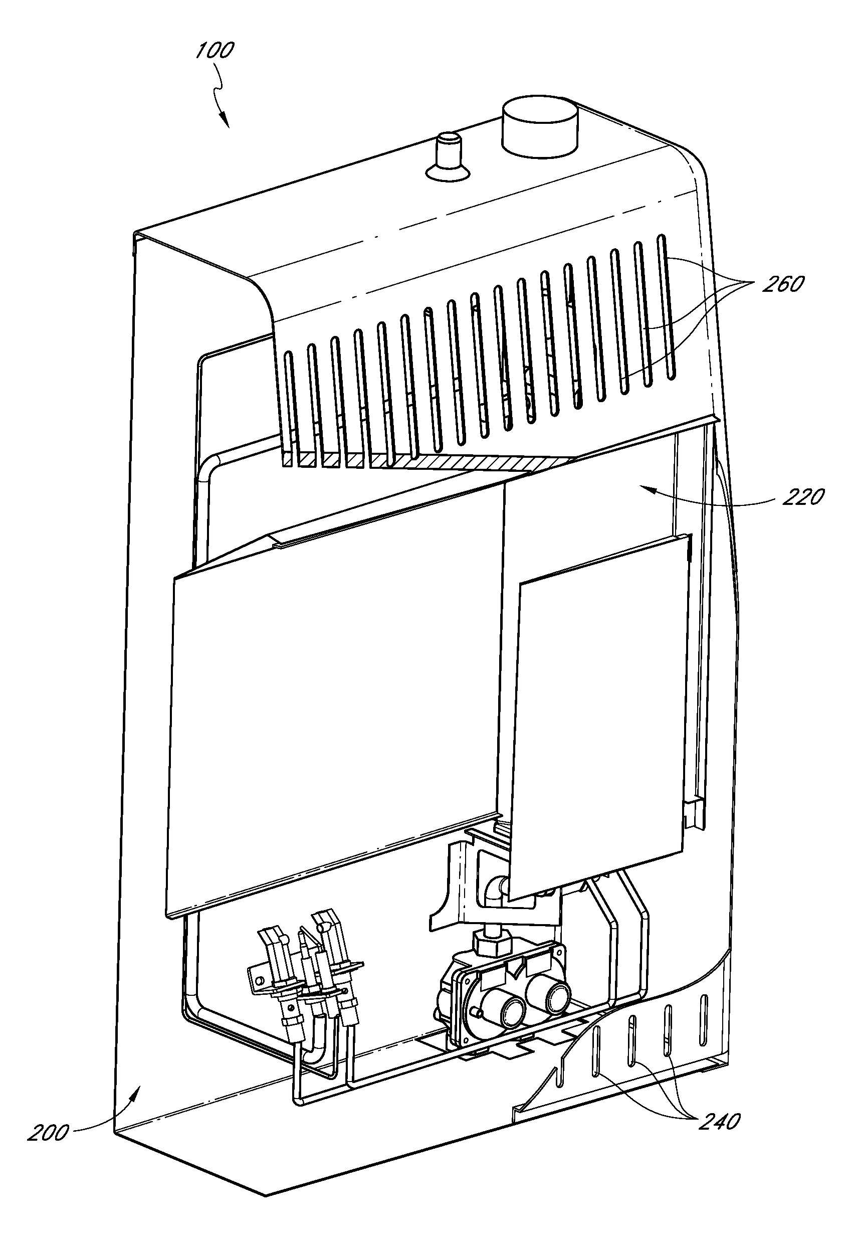
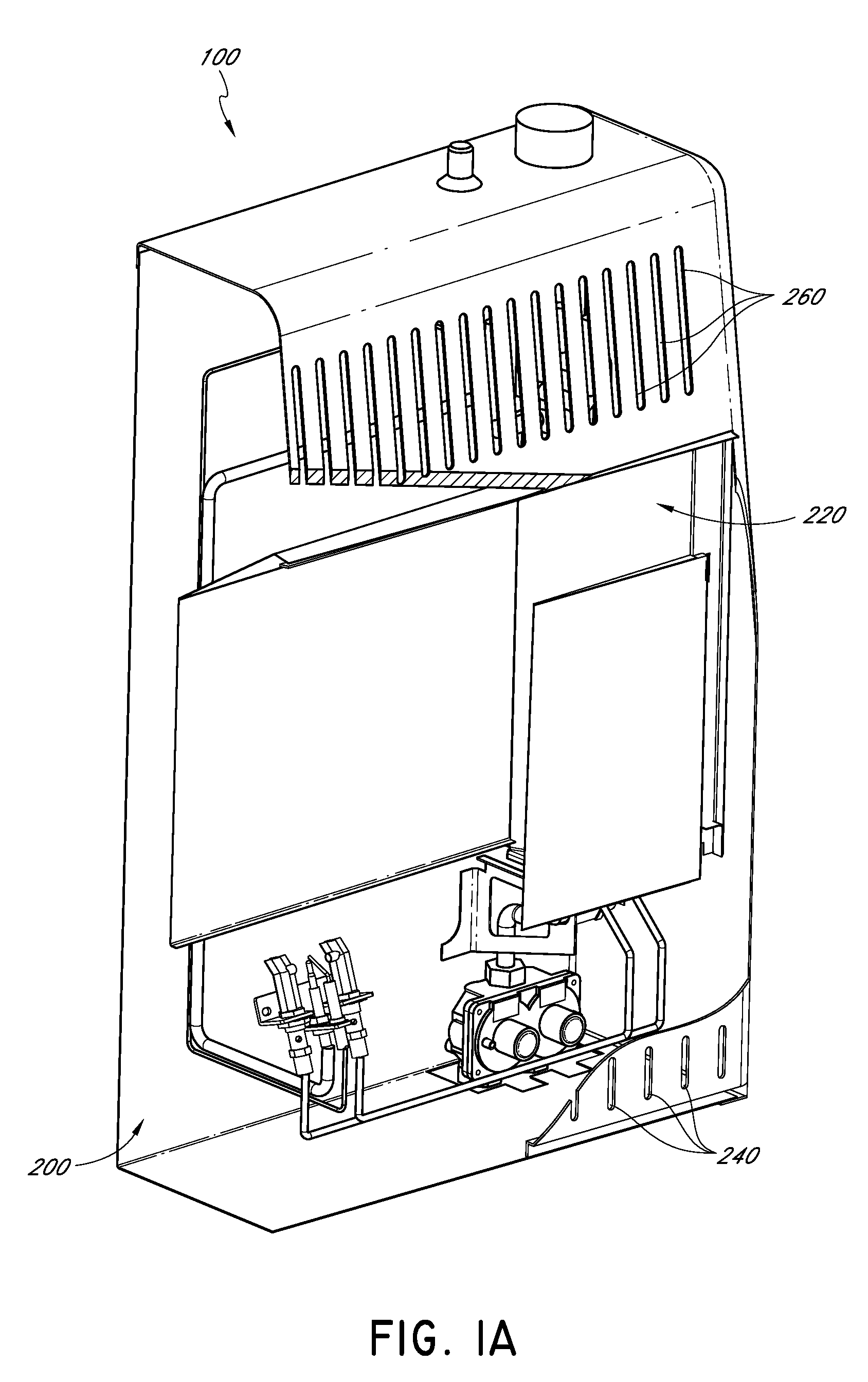
[0014] FIG. 1A is a perspective cutaway view of a portion of one embodiment of a heater configured to operate using either a first fuel source or a second fuel source;
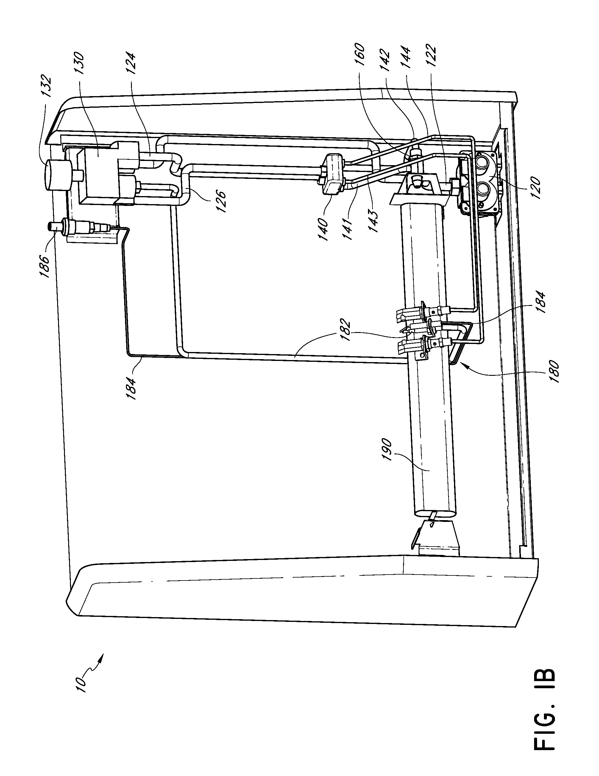
[0015] FIG. 1B is a perspective cutaway view of the heater of FIG. 1A;
[0016] FIG. 2A is a perspective view of one embodiment of a heater configured to operate using either a first fuel source or a second fuel source;
[0017] FIG. 2B is an exploded perspective view of the heater of FIG. 2A;
[0018] FIG. 2C is a perspective view of one portion of the heater of FIG. 2A;
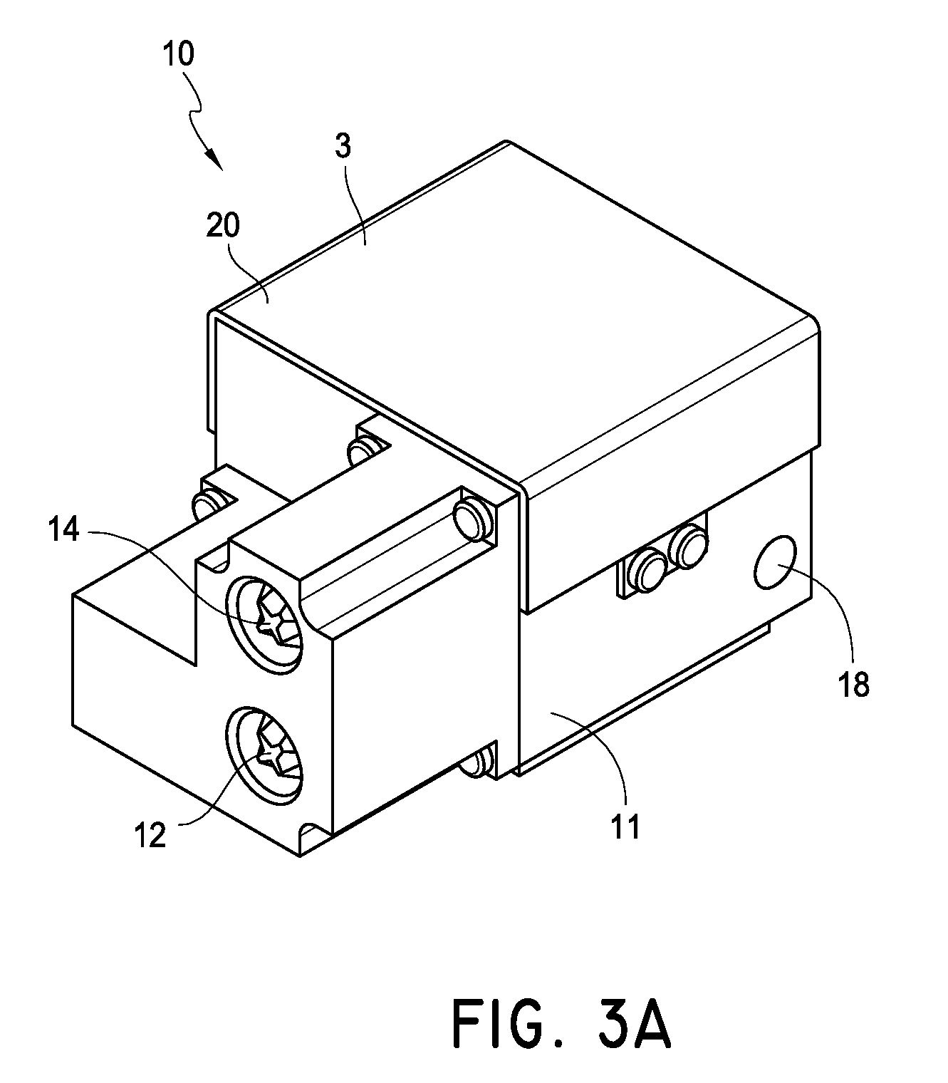
[0019] FIG. 3A is perspective view of one embodiment of a heating source;
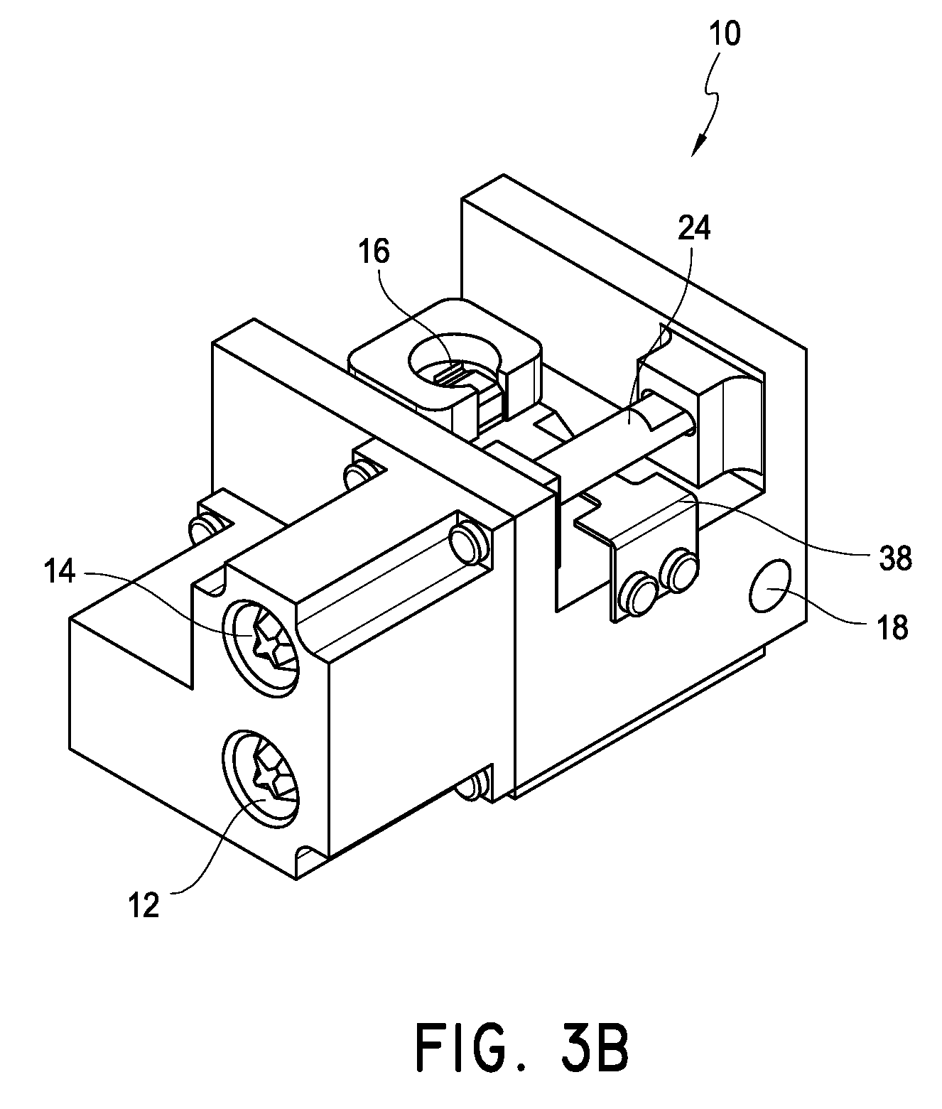
[0020] FIG. 3B is a perspective view of the partially disassembled heating source of FIG. 3A;
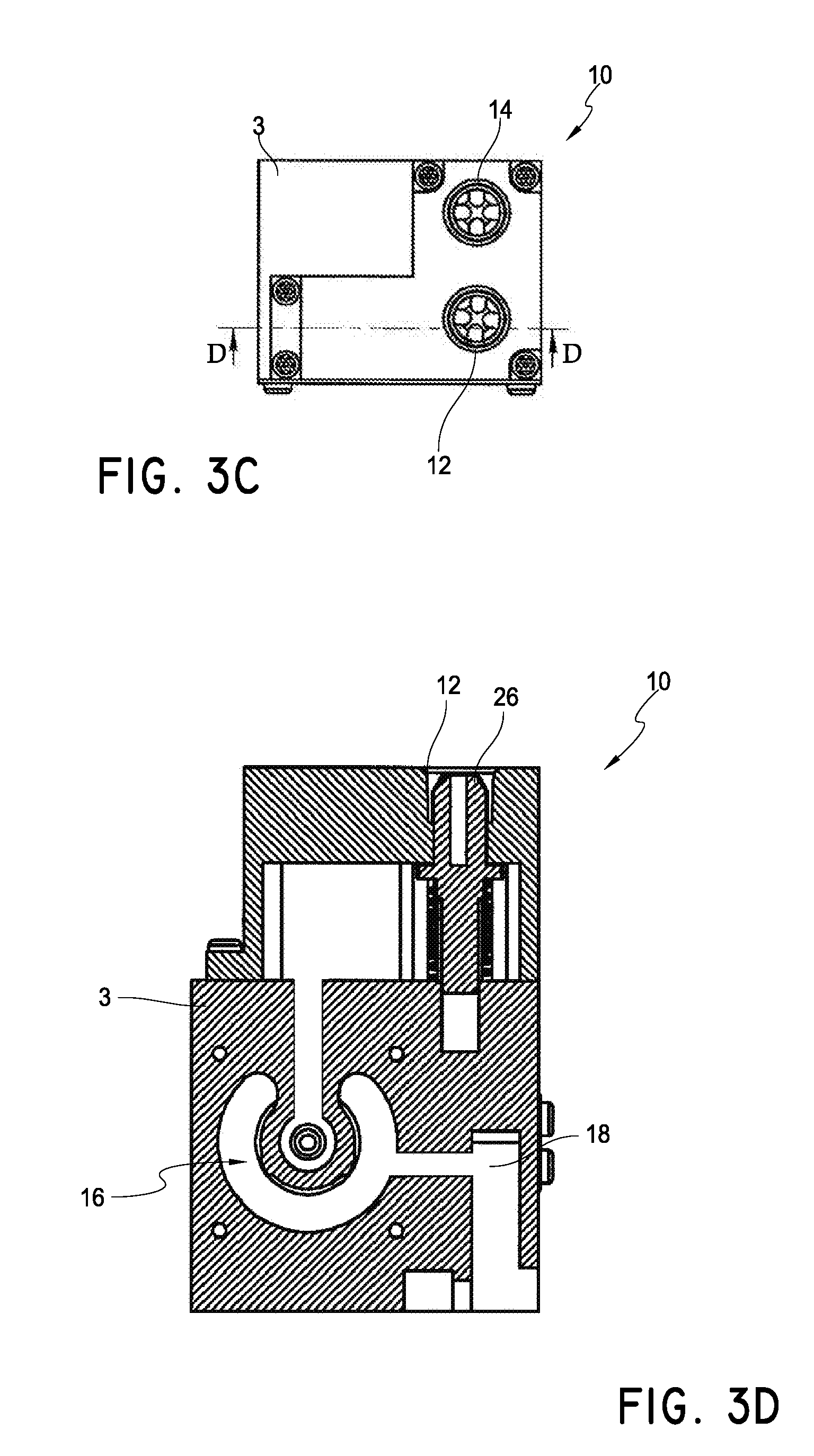
[0021] FIG. 3C is a front view of the heating source of FIG. 3A;
[0022] FIG. 3D is a cross-section of the heating source taken alone line A-A of FIG. 3C;
[0023] FIG. 4 is a top view of the partially disassembled heating source of FIG. 3B;
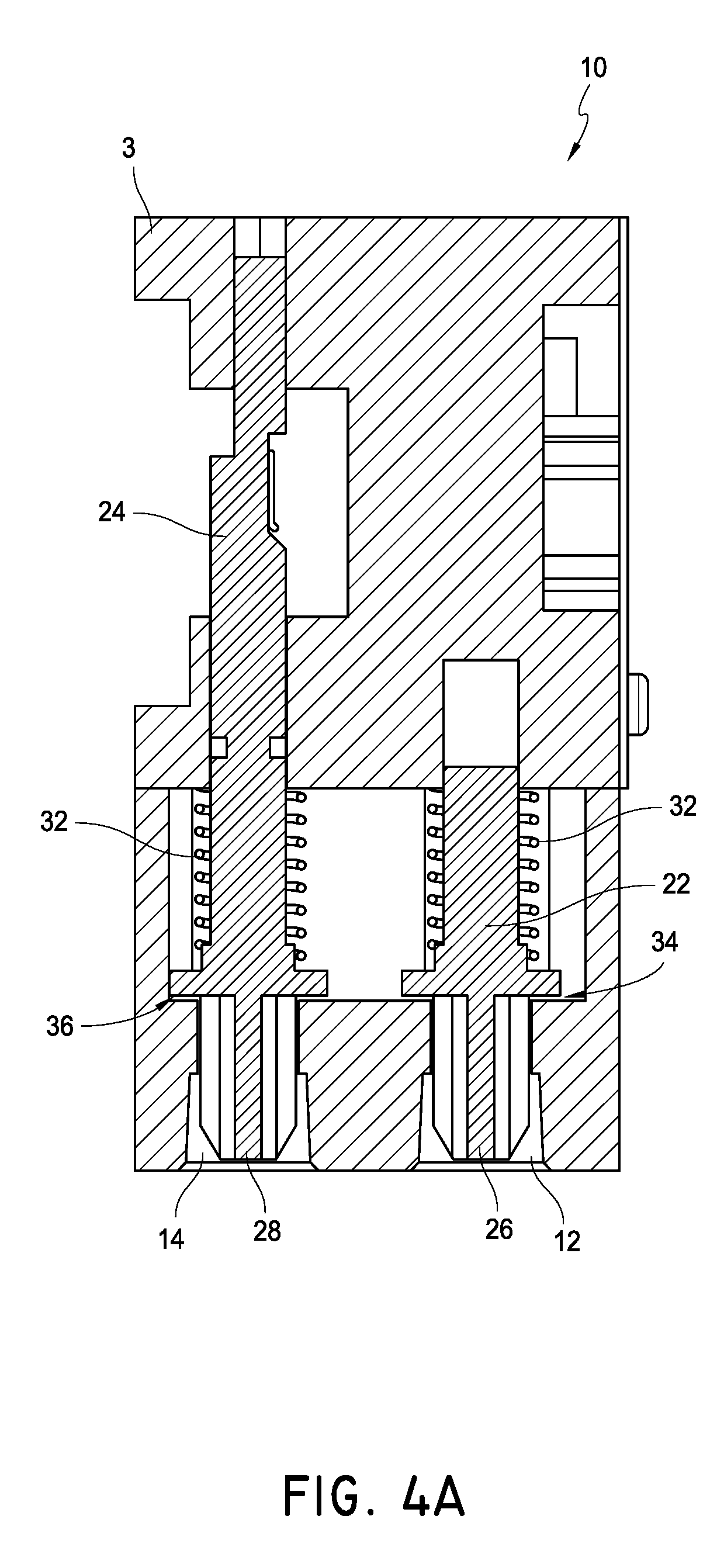
[0024] FIG. 4A is a cross-section of a heating source taken along line A-A of FIG. 4;
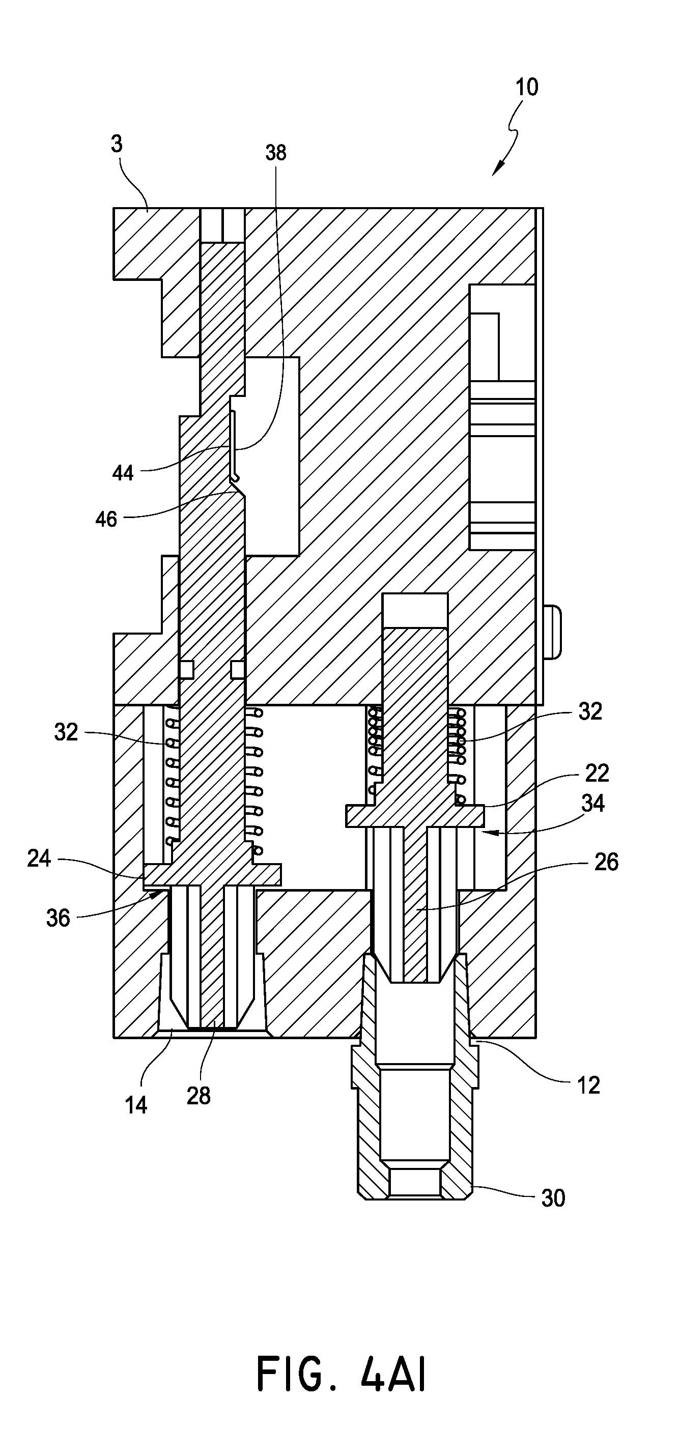
[0025] FIGS. 4A1 and 4A2 show the heating source of FIG. 4A in two different positions;
[0026] FIGS. 4B1 and 4B2 are cross-sections of the heating source of FIG. 4A taken along line B-B in two different positions;
[0027] FIGS. 5A-D are schematic views of different embodiments of heating source;
[0028] FIGS. 6A-B are schematic views of different embodiments of heating sources;
[0029] FIG. 7 is a perspective view of another embodiment of a partially disassembled heating source;
[0030] FIG. 8 is a front view of the heating source of FIG. 7;
[0031] FIG. 8A is a cross-sectional view of the heating source of FIG. 8 taken along line A-A;
[0032] FIG. 9 is a top view of the partially disassembled heating source of FIG. 7;
[0033] FIG. 9A is a cross-section of a heating source taken along line A-A of FIG. 9;
[0034] FIGS. 9A1 and 9A2 show the heating source of FIG. 9A in two different positions;
[0035] FIGS. 9B and 9C are cross-sections of the heating source of FIG. 9A taken along line C-C in two different positions;
[0036] FIGS. 10, 10A, and 10B illustrate perspective views of different embodiments of heating sources;
[0037] FIGS. 11A and 11B are cross-sections of a heating source in two different positions;
[0038] FIG. 12 is a cross-section of another heating source;
[0039] FIG. 13 is a cross-section of still another heating source;
[0040] FIG. 14 shows a perspective view of another embodiment of a heating source;
[0041] FIG. 15 is a cross-section of the heating source of FIG. 14;
[0042] FIG. 16 is a cross-section of the heating source of FIG. 14 showing the pressure regulators;
[0043] FIG. 17 is a cross-section of the heating source of FIG. 14 showing two valves;
[0044] FIG. 18A is a perspective view of one embodiment of a fuel selector valve;
[0045] FIG. 18B is a cutaway of the valve of FIG. 18A;
[0046] FIGS. 19A and 19B are cross-sections of the valve of FIG. 18A;
[0047] FIG. 20 is a top view of another embodiment of a fuel selector valve;
[0048] FIG. 21 is a cross-section of the fuel selector valve of FIG. 20;
[0049] FIGS. 22A and 22B are cross-sections of the fuel selector valve of FIG. 20 with an attached fuel source;
[0050] FIG. 23 is a cross-section of the fuel selector valve of FIG. 20, taken along the line 23-23 of FIG. 22B;
[0051] FIG. 24 is a perspective view of a portion of a heater;
[0052] FIG. 25 is a perspective cross-section view of a valve from FIG. 24;
[0053] FIG. 25A is a cross-section view of a valve used with a first fuel at a first fluid pressure;
[0054] FIG. 25B is a cross-section view of the valve of FIG. 25 with the first fuel at a second fluid pressure;
[0055] FIG. 26 is a cross-section view of the valve of FIG. 25 with a second fuel;
[0056] FIG. 27 is a perspective view of a portion of a heater;
[0057] FIG. 28 is a perspective cross-section view of a valve from FIG. 27;
[0058] FIG. 29A is a cross-section view of a valve used with a first fuel at a first fluid pressure;
[0059] FIG. 29B is a cross-section view of the valve of FIG. 28 with the first fuel at a second fluid pressure;
[0060] FIG. 30 is a cross-section view of the valve of FIG. 28 with a second fuel;
[0061] FIG. 31 is a schematic drawing illustrating a dual fuel selectable barbeque in a control default condition for delivery of natural gas to one or more burners;
[0062] FIG. 32A is a schematic drawing illustrating the dual fuel selectable barbeque of FIG. 31, in a control activated condition for delivery of propane (LP) gas to one or more burners;
[0063] FIG. 32B illustrates an exemplary positive output voltage pulse to activate one or more solenoid valves to provide for delivery of LP gas;
[0064] FIG. 33A is a schematic drawing illustrating the dual fuel selectable barbeque of FIG. 31, in a control reset condition for delivery of natural gas to one or more burners after the activation of a reset button to revert the barbeque to the control default condition (FIG. 31) from a control activated condition (FIG. 32); and
[0065] FIG. 33B illustrates an exemplary negative output voltage pulse to deactivate one or more solenoid valves to provide for delivery of natural gas.
[0066] Unless otherwise indicated illustrations in the figures are not necessarily drawn to scale.
[0067] The invention and its various embodiments can now be better understood by turning to the following detailed description wherein illustrated embodiments are described. It is to be expressly understood that the illustrated embodiments are set forth as examples and not by way of limitations on the invention as ultimately defined in the claims.
[0068] DETAILED DESCRIPTION OF THE PREFERRED EMBODIMENTS AND BEST MODE OF INVENTION
[0069] Many varieties of space heaters, fireplaces, stoves, ovens, boilers, fireplace inserts, gas logs, and other heat-producing devices employ combustible fuels, such as liquid propane and natural gas. These devices generally are designed to operate with a single fuel type at a specific pressure. For example, as one having skill in the art would appreciate, some gas heaters that are configured to be installed on a wall or a floor operate with natural gas at a pressure in a range from about 3 inches of water column to about 6 inches of water column, while others operate with liquid propane at a pressure in a range from about 8 inches of water column to about 12 inches of water column.
[0070] In many instances, the operability of such devices with only a single fuel source is disadvantageous for distributors, retailers, and/or consumers. For example, retail stores often try to predict the demand for natural gas units versus liquid propane units over a given season, and accordingly stock their shelves and/or warehouses with a percentage of each variety of device. Should such predictions prove incorrect, stores can be left with unsold units when the demand for one type of unit was less than expected, while some potential customers can be left waiting through shipping delays or even be turned away empty-handed when the demand for one type of unit was greater than expected. Either case can result in financial and other costs to the stores. Additionally, some consumers can be disappointed to discover that the styles or models of stoves, fireplaces or other device, with which they wish to improve their homes, are incompatible with the fuel sources with which their homes are serviced.
[0071] Certain advantageous embodiments disclosed herein reduce or eliminate these and other problems associated with devices having heating sources that operate with only a single type of fuel source. Furthermore, although certain of the embodiments described hereafter are presented in the context of vent-free heating systems, the apparatus and devices disclosed and enabled herein can benefit a wide variety of other applications and appliances.
[0072] FIG. 1A illustrates one embodiment of a heater 100. The heater 100 can be a vent-free infrared heater, a vent-free blue flame heater, or some other variety of heater, such as a direct vent heater. Some embodiments include boilers, stoves, dryers, fireplaces, gas logs, etc. Other configurations are also possible for the heater 100. In many embodiments, the heater 100 is configured to be mounted to a wall or a floor or to otherwise rest in a substantially static position. In other embodiments, the heater 100 is configured to move within a limited range. In still other embodiments, the heater 100 is portable.
[0073] The heater 100 can comprise a housing 200. The housing 200 can include metal or some other suitable material for providing structure to the heater 100 without melting or otherwise deforming in a heated environment. In the illustrated embodiment, the housing 200 comprises a window 220, one or more intake vents 240 and one or more outlet vents 260. Heated air and/or radiant energy can pass through the window 220. Air can flow into the heater 100 through the one or more intake vents 240 and heated air can flow out of the heater 100 through the outlet vents 260.
[0074] With reference to FIG. 1B, in certain embodiments, the heater 100 includes a regulator 120. The regulator 120 can be coupled with an output line or intake line, conduit, or pipe 122. The intake pipe 122 can be coupled with a heater control valve 130, which, in some embodiments, includes a knob 132. As illustrated, the heater control valve 130 is coupled to a fuel supply pipe 124 and an oxygen depletion sensor (ODS) pipe 126, each of which can be coupled with a fluid flow controller 140. The fluid flow controller 140 can be coupled with a first nozzle line 141, a second nozzle line 142, a first ODS line 143, and a second ODS line 144. In some embodiments, the first and the second nozzle lines 141, 142 are coupled with a nozzle 160, and the first and the second ODS lines 143, 144 are coupled with an ODS 180. In some embodiments, the ODS comprises a thermocouple 182, which can be coupled with the heater control valve 130, and an igniter line 184, which can be coupled with an igniter switch 186. Each of the pipes 122, 124, and 126 and the lines 141-144 can define a fluid passageway or flow channel through which a fluid can move or flow.
[0075] In some embodiments, including the illustrated embodiment, the heater 100 comprises a burner 190. The ODS 180 can be mounted to the burner 190, as shown. The nozzle 160 can be positioned to discharge a fluid, which may be a gas, liquid, or combination thereof into the burner 190. For purposes of brevity, recitation of the term "gas or liquid" hereafter shall also include the possibility of a combination of a gas and a liquid. In addition, as used herein, the term "fluid" is a broad term used in its ordinary sense, and includes materials or substances capable of fluid flow, such as gases, liquids, and combinations thereof.
[0076] Where the heater 100 is a dual fuel heater, either a first or a second fluid is introduced into the heater 100 through the regulator 120. Still referring to FIG. 1B, the first or the second fluid proceeds from the regulator 120 through the intake pipe 122 to the heater control valve 130. The heater control valve 130 can permit a portion of the first or the second fluid to flow into the fuel supply pipe 124 and permit another portion of the first or the second fluid to flow into the ODS pipe 126. From the heater control valve 130, the first or the second fluid can proceed to the fluid flow controller 140. In many embodiments, the fluid flow controller 140 is configured to channel the respective portions of the first fluid from the fuel supply pipe 124 to the first nozzle line 141 and from the ODS pipe 126 to the first ODS line 143 when the fluid flow controller 140 is in a first state, and is configured to channel the respective portions of the second fluid from the fuel supply pipe 124 to the second nozzle line 142 and from the ODS pipe 126 to the second ODS line 144 when the fluid flow controller 140 is in a second state.
[0077] In certain embodiments, when the fluid flow controller 140 is in the first state, a portion of the first fluid proceeds through the first nozzle line 141, through the nozzle 160 and is delivered to the burner 190, and a portion of the first fluid proceeds through the first ODS line 143 to the ODS 180. Similarly, when the fluid flow controller 140 is in the second state, a portion of the second fluid proceeds through the nozzle 160 and another portion proceeds to the ODS 180. As discussed in more detail below, other configurations are also possible.
[0078] FIGS. 2A-2C illustrate another embodiment of a heater 100' such as a BBQ grill. In some embodiments, the heater 100' is configured to be mounted to a wall or a floor or to otherwise rest in a substantially static position. In other embodiments, the
[0079] heater 100' is configured to move within a limited range. In still other embodiments, the heater 100' is portable.
[0080] With reference to FIG. 2A, the heater can comprise a housing 200'. The housing 200' can include metal or some other suitable material for providing structure to the heater 100' without melting or otherwise deforming in a heated environment. In the illustrated embodiment, the housing 200' comprises a cover 250, which can preferably be moved from a closed to an open position, allowing heated air and/or radiant energy to pass out of the housing 200'. In some embodiments, a grill 170 can be positioned within or near the housing.
[0081] In some embodiments, the heater 100' can also include a frame 150 attached to the housing. The frame can support and/or elevate the housing. The frame can also include one or more wheels 152, which can make it easier to move the heater 100'.
[0082] FIG. 2B illustrates an exploded view of the heater 100'. As illustrated, the heater can include a fuel selector valve 3, embodiments of which are described in more detail below. Where the heater 100' is a dual fuel heater, either a first or second fuel can be introduced into the heater 100' through the fuel selector valve 3. The fuel can flow to one or more burners 190'. In some embodiments, the heater 100' can have one or more different types and/or sizes of burners. As shown, the heater 100' has a number of burners within the BBQ grill, as well as a side burner. In some embodiments, one or more of the burners can have a control valve 130' associated with it, and/or have a burner cover 192. In some embodiments a control valve can include a knob 132'.
[0083] FIG. 2C illustrates a more detailed view of embodiments of a fuel selector valve 3 and burners 190'. As illustrated, in some embodiments the fuel selector valve 3 can have a first outlet 18 that leads to a first flow path 71, and a second outlet 19 that leads to a second flow path 73. The first and second flow paths can intersect at a common or shared flow path 75. In some embodiments, the second flow path can pass through a pressure regulator 16 before joining with the first flow path.
[0084] A heating assembly or heating source 10 that can be used with the heater 100, 100' or other gas appliances, will now be described. The heating source 10 can be configured such that the installer of the gas appliance can connect the assembly to one of two fuels, such as either a supply of natural gas (NG) or a supply of propane (LP) and the assembly will desirably operate in the standard mode (with respect to efficiency and flame size and color) for either gas.
[0085] Looking at FIGS. 3A-4B2, a heating source 10 can comprise a fuel selector valve 3. The fuel selector valve 3 can be used for selecting between two different fuels and for setting certain parameters, such as one or more flow paths, and/or a setting on one or more pressure regulators based on the desired and selected fuel. The fuel selector valve 3 can have a first mode configured to direct a flow of a first fuel (such as NG) in a first path through the fuel selector valve 3 and a second mode configured to direct a flow of a second fuel (such as LP) in a second path through the fuel selector valve 3.
[0086] The fuel selector valve 3 can further comprise first and second fuel source connections or hook-ups 12, 14. The fuel selector valve 3 can connect to one of two different fuel sources, each fuel source having a different type of fuel therein. For example, one fuel source can be a cylinder of LP and another fuel source can be a NG fuel line in a house, connected to a city gas line. The first and second fuel source connections 12, 14 can comprise any type of connection such as a threaded connection, a locking connection, an advance and twist type connection, etc.
[0087] An embodiment of a fuel selector valve 3 is shown in FIG. 3A with a housing 11 and a cover 20. The cover has been removed in FIG. 3B revealing some of the internal components of the illustrated embodiment. A pressure regulator 16 is positioned within the housing such that fluid entering the fuel selector valve 3 via either the first or second fuel source connection 12, 14 can be directed to the pressure regulator 16. FIG. 3D shows a cross-section of the selector valve 3 showing the flow path between the fuel source connections and the pressure regulator. Fuel from the pressure regulator 16 can then flow to the outlet 18, as can also be seen with reference to FIG. 3D. The fuel can then flow to various other components, such as a burner. In some embodiments, the fuel selector valve 3 has two separate pressure regulators such that each fuel source connection directs fuel to a specific pressure regulator which can then travel to the outlet.
[0088] The fuel selector valve 3 can be configured to select one or more flow paths through the fuel selector valve 3 and/or to set a parameter of the fuel selector valve. For example, the fuel selector valve 3 can include one or more valves, where the position of the valve can determine one or more flow paths through the fuel selector valve 3, such as a fluid exit or entry pathway. As another example, the fuel selector valve 3 can control certain parameters of the pressure regulator 16.
[0089] With reference to FIGS. 4-4A2, it can be seen that the fuel selector valve 3 can include one or more actuation members 22, 24. The actuation members 22, 24 can be used for many purposes such as to select one or more flow paths through the fuel selector valve 3 and/or to set a parameter of the fuel selector valve. The one or more actuation members can be provided in the fuel selector valve 3 in many ways. As shown, the actuation members are spring loaded rods that can be advanced in a linear motion. An actuation member can be one or more of a linkage, a rod, an electric or mechanical button, a pin, a slider, a gear, a cam, etc.
[0090] As shown, the actuation member 22 has an end 26 positioned within the first fuel source connection 12. A connector 30 can be attached to the first fuel source connection 12 by advancing the connector into the first fuel source connection 12. This can force the actuation member end 26 into the housing of the fuel selector valve 3. This force then counteracts a spring force provided by a spring 32 to open a valve 34.
[0091] FIG. 4A1 shows the open valve 34 with the connector 30 attached to the first fuel source connection 12. The connector 30 can be part of a fuel source to provide fuel to the heater assembly 10. With the valve 34 in the open position, fuel from the fuel source can flow through the connector 30 and into the fuel selector valve 3. In particular, as shown, fuel can flow into the first fuel source connection 12, then to the pressure regulator 16 and finally out of the fuel selector valve 3 by way of outlet 18 (FIG. 3A-3B).
[0092] Alternatively, the connector 30 can be connected to the second fuel source connection 14. This can open the valve 36 by pressing on the end 28 of the second actuation member 24. Fuel can then flow from the fuel source through the connector 30 into the fuel source connection 14. The fuel can then flow to the pressure regulator 16 and out through outlet 18.
[0093] The presence of two valves 34, 36, one at each fuel source connection 12, 14, can prevent fuel from exiting the fuel selector valve 3 undesirably, as well as preventing other undesirable materials from entering the fuel selector valve 3. In some embodiments, the fuel selector valve can utilize a cap or plug to block the unused fuel source connection. This may be in addition to or instead of one or more valves at the fuel source connections. For example, in some embodiments the actuation member 24 does not include a valve at the fuel source connection 14.
[0094] In addition to or instead of providing a valve 36 at the inlet or fuel source connection 14, the actuation member 24 can be in a position to control a parameter of the pressure regulator 16. Referring back to FIGS. 3B and 4, it can be seen that an arm 38 extends between the actuation member 24 and the pressure regulator 16. The actuation member 24 can act on the arm, determining the position of the arm 38. This position can be seen by comparing the position of the arm 38 in FIGS. 4A1 and 4A2, as well as 4B1 and 4B2. The position of the arm 38 can then determine the height (H1, H3) of the spring 40 within the pressure regulator. That is, though the length of the spring is constant, the height H1 of the spring when the diaphragm is in a first position shown in FIG. 4B1 is greater than the height H3 of the spring when the spring is in the position shown in FIG. 4B2. As shown, the arm 38 contacts a cap 41 that is connected to the spring 40. The height of the spring 40 can be a factor in determining the force required to move the diaphragm 42. The spring height can be used to preset the pressure settings of the pressure regulator. Thus, the spring can be tensioned to regulate the pressure of the incoming fuel depending on whether the first or second fuel source is utilized.
[0095] In another embodiment, the actuation member contacts the pressure regulator 16 directly, such as at the cap 41, without the assistance of an arm or other device to set the regulating pressure of the pressure regulator.
[0096] The pressure regulator 16 can be set to a first position as shown in FIG. 4B1. The initial position can allow for flow control of the first fuel at an initial predetermined pressure or pressure range. The initial predetermined pressure or pressure range is lower than the second predetermined pressure or pressure range based on the second position as shown in FIG. 4B2. For example, the predetermined selected pressure can depend at least in part on the particular fuel used, and may desirably provide for safe and efficient fuel combustion and reduce, mitigate, or minimize undesirable emissions and pollution. In some embodiments, the first pressure can be set to be within the range of about 3 inches of water column to about 6 inches of water column, including all values and subranges therebetween. In some embodiments, the threshold or flow-terminating pressure is about 3 inches of water column, about 4 inches of water column, about 5 inches of water column, or about 6 inches of water column.
[0097] In some embodiments, the second pressure can be set to be within the range of about 8 inches of water column to about 12 inches of water column, including all values and sub-ranges therebetween. In some embodiments, the second threshold or flow terminating pressure is about equal to 8 inches of water column, about 9 inches of water column, about 10 inches of water column, about 11 inches of water column, or about 12 inches of water column.
[0098] When natural gas is the first fuel and propane is the second fuel, the first pressure, pressure range and threshold pressure are less than the second pressure, pressure range and threshold pressure. Stated differently, in some embodiments, when natural gas is the first fuel and propane is the second fuel, the second pressure, pressure range and threshold pressure are greater than the first pressure, pressure range and threshold pressure.
[0099] The pressure regulator 16 can function in a similar manner to that discussed in U.S. application Ser. No. 11/443,484, filed May 30, 2006, now U.S. Pat. No. 7,607,426, incorporated herein by reference and made a part of this specification; with particular reference to the discussion on pressure regulators at columns 3-9 and FIGS. 3-7 of the issued patent.
[0100] The pressure settings can be further adjusted by tensioning of a screw or other device 41 that allows for flow control of the fuel at a predetermined pressure or pressure range and selectively maintains an orifice open so that the fuel can flow through spring-loaded valve or valve assembly of the pressure regulator. If the pressure exceeds a threshold pressure, a plunger seat 43 can be pushed towards a seal ring 45 to seal off the orifice, thereby closing the pressure regulator.
[0101] The fuel selector valve 3 can permit the flow of fuel from one or more pressure regulators, through the fuel selector valve 3 and into additional components. The additional components can be, for example, the heater control valve 130, the fluid flow controller 140, the nozzle 160, etc. In some embodiments, the additional components can comprise a control valve which comprises at least one of a manual valve, a thermostat valve, an AC solenoid, a DC solenoid and a flame adjustment motor. In various embodiments, the additional components mayor may not comprise part of the heating source 10. The additional components can be configured to use the fuel, such as for combustion, and/or to direct one or more lines of fuel to other uses or areas of the heater 100, 100' or other appliance.
[0102] Returning now to FIGS. 4A1-4B2, the functioning of the arm 38 and the actuation member 24 will be described in more detail. The actuation member 24 can have a varying or undulating surface that engages the arm 38. The arm 38 can move with the varying surface thereby changing the position of the arm 38. The arm 38 can be made from a resilient flexible material, such as metal or plastic, but can also be rigid. The arm as shown is a flexible material that can be moved and bent between positions with a resiliency to return to an unbent or less bent position. In other embodiments, the arm can be a linkage, a pinned rotating arm, a member suspended between the actuation member and the pressure regulator, etc. The arm 38 can be elongate, have spring qualities, be biased upwards, be a bent metal arm or beam, etc.
[0103] The actuation member 24 can have sections of different heights (H2, H4). For example, the actuation member 24 can include flat spots or sections with a diameter different than adjacent sections. As can be seen, the actuation member includes a flat portion 44 with a transition portion 46 that extends between the initial outer diameter of the cylindrical rod and the flat portion 44. Alternatively, the portion 44 can have smaller diameter than the initial outer diameter of the rod. The rod can extend along a longitudinal axis and have a plurality of longitudinal cross-sections of different shapes. The actuation member 24 can be a type of cam and can also be shapes, besides cylindrical, and can have a surface that varies to provide different heights to the arm 38 for engaging the arm and setting the pressure at the pressure regulator 16.
[0104] Looking now to FIG. 5A, a schematic diagram of a heating source with a fuel selector valve 3 is illustrated. The illustrated fuel selector valve 3 can be similar to that described above with reference to FIGS. 3A-4B2. A fuel source can be connected to the fuel selector valve 3 via one of the fuel source connections 12, 14. The act of connecting the fuel source to the fuel selector valve 3 can set the pressure regulator to the desired pressure if it is not already at the desired pressure. Thus, selecting the proper fuel source connection can determine and sometimes set the pressure at the pressure regulator. It will be understood that one fuel source connection may allow fluid to flow through a default or preset path while the other fuel source connection may change the path including changing other characteristics of the system along the path such as the pressure regulator setting. In some embodiments, both fuel source connections may change the path and/or other characteristics.
[0105] The fuel selector valve 3 can permit the flow of fuel from the pressure regulator 16 through the fuel selector valve 3 and then into additional components. The additional components can be, for example, the heater control valve 130, the fluid flow controller 140, the nozzle 160, etc. In some embodiments, the additional components can comprise a control valve which comprises at least one of a manual valve, a thermostat valve, an AC solenoid, a DC solenoid and a flame adjustment motor. In various embodiments, the additional components mayor may not comprise part of the heating source 10. The additional components can be configured to use the fuel, such as for combustion, and/or to direct one or more lines of fuel to other uses or areas of the heater 100, 100' or other appliance.
[0106] FIG. 5B illustrates a schematic diagram of another embodiment of a heating source with a fuel selector valve 3. The illustrated fuel selector valve can be similar to that described below with reference to FIGS. 18A-19B. A fuel source can be connected to the fuel selector valve 3 via one of the fuel source connections 12, 14. The act of connecting the fuel source to the fuel selector valve 3 can determine whether a flow path from either fuel source connection 12, 14 is open or closed.
[0107] The fuel selector valve 3 can be arranged such that fluid flowing from the second fuel source connection 14 passes through a pressure regulator through which fluid flowing from the first fuel source connection 12 does not pass. In some embodiments, as is illustrated, the pressure regulator can be outside of the fuel selector valve, although in some embodiments it can be within it. As illustrated, fluid flowing through either fuel connection source can ultimately end up in the same line, from which the fluid can flow into additional components. As above, the additional components can be, for example, a heater control valve 130, a fluid flow controller 140, a nozzle 160, etc. In some embodiments, the additional components can comprise a control valve which comprises at least one of a manual valve, a thermostat valve, an AC solenoid, a DC solenoid and a flame adjustment motor. In various embodiments, the additional components mayor may not comprise part of the heating source 10. The additional components can be configured to use the fuel, such as for combustion, and/or to direct one or more lines of fuel to other uses or areas of the heater 100, 100' or other appliance.
[0108] In further embodiments, the fuel selector valve 3 can be arranged such that fluid flowing from the second fuel source connection 14 passes through a first pressure regulator and fluid flowing from the first fuel source connection 12 passes through a second pressure regulator. The pressure regulators can be either inside of or outside of the fuel selector valve. Similar to that illustrated in FIG. 5B, fluid flowing through either fuel connection source can ultimately end up in the same line, from which the fluid can flow into additional components.
[0109] FIGS. 5C and 5D show additional embodiments of heating source where selecting the fuel source connection can set additional parameters. The fuel selector valve of FIG. 5C includes a valve 48. The valve 48 has one inlet and two outlets, such that one outlet can be closed while the other is open. The valve 48 can have an initial position where one of the outlets is open and a secondary position where the other outlet is open. The selection of the fuel source connection can determine whether the valve is in the initial or secondary position. For example, selecting the first fuel source connection 12 can allow fuel flow through the initial configuration of the heating source, while selecting the second fuel source connection 14 can move the pressure regulator 16 and the valve 48 to their secondary configurations.
[0110] In other embodiments, the two outlets can both have separate open and closed positions with separate valves located at each outlet. Thus, the valve 48 can comprise two valves. The selection of the fuel source connection can determine which valve is opened. For example, selecting the first fuel source connection 12 can allow fuel flow through the initial configuration of the pressure regulator and can open the first valve at one of the outlets. Selecting the second fuel source connection 14 can move the pressure regulator 16 to its secondary configuration and open the second valve at the other of the outlets.
[0111] FIG. 5D illustrates a fuel selector valve having two valves 48, 50. In addition to setting the pressure regulator, selecting the fuel source connection can also determine how the fuel flows through the valves 48, 50. For example, one selection can allow the fuel to follow the upward arrows, while the other selection can allow the fuel to follow the downward arrows. In addition, the fuel selector valve can also direct the fuel out of the fuel selector valve after the pressure regulator 16, and then receive the fuel again. The fuel can be directed to other components 52 that then direct the fuel, or some of the fuel back to the fuel selector valve. It should be understood that the fuel selector valve show in FIG. 5C can also include other components 52 between the pressure regulator 16 and the valve 48. The heating source can include the fuel selector valve and one or more of the other components.
[0112] The other component 52 can preferably be a control valve. In some embodiments, the control valve can comprise at least one of a manual valve, a thermostat valve, an AC solenoid, a DC solenoid and a flame adjustment motor. For example, the control valve 52 can include two solenoids. Each solenoid can control the flow of fuel to one of the valves 48, 50. The valves can then direct fuel to additional components such as a pilot light or oxygen depletion sensor and to a nozzle. In some embodiments, each line leaving the valve can be configured to direct a particular type of fuel to a component configured specific to that type of fuel. For example, one valve may have two lines with each line connected to a different nozzle. The two nozzles can each have a different sized orifice and/or air hole and each can be configured for a particular fuel type.
[0113] Turning now to FIGS. 6A and 6B, additional embodiments of heating sources are shown. The heating source of FIG. 6A is very similar to that shown in FIG. 5D. One difference is that the fuel selector valve of FIG. 6A includes two pressure regulators 16'. The two pressure regulators 16' can be preset to a particular pressure or pressure range. As there is only one line leading to each pressure regulator, the pressure regulators do not need to be changeable between two different pressures as discussed above with reference to FIGS. 5A-5D. In addition, similar to FIGS. 5C and 5D, either one of the fuel source connections 12, 14 or both can determine and/or change a path through the fuel selector valve. For example, each of valves 48 and 50 can comprise one valve or two valves as described above.
[0114] FIG. 6B shows another embodiment where the control valve 52 returns two flows of fuel to the fuel selector valve. One flow of fuel is directed to a valve 48 and one flow passes through the fuel selector valve but does not have separate paths dependent on the fuel type.
[0115] In each of the embodiments shown in FIGS. 5A-6B, the fuel selector valve may also include valves in or near the fuel source connections 12, 14. This can help to control the flow of fuel into the fuel selector valve as has been previously discussed.
[0116] Turning now to FIGS. 7-9C, another embodiment of heating source 10 is shown. It will be understood that parts of this heating source can function in a similar manner to the heating source shown and described with reference to FIGS. 3A-4B2. Thus, similar reference numbers are used. For example, the pressure regulator 16 functions in the same way in both illustrated embodiments. In addition, the embodiment of FIGS. 7-9C is conceptually similar to the schematic diagram shown and described with reference to FIG. 5D.
[0117] Looking to FIG. 7, it can be seen that a control valve 52 having two solenoids 54, 56 is connected to the side of the fuel selector valve 3. The fuel selector valve also includes two valves 48, 50. FIGS. 8 and 8A show the fuel selector valve 3 in relation to the control valve 52. A fluid, such as fuel, can flow from one of the fuel source connections 12, 14 flows through the pressure regulator 16 to the control valve 52. The fluid flow will first encounter the first solenoid 54. The first solenoid 54 has a valve 58 that can control flow past the first solenoid 54. When the valve 58 is open, fluid can flow to both the second solenoid 56 and to the valve 48. The second solenoid 56 also has a valve 60 which can open or close to control fuel flow to the valve 50. In some embodiments, the valve 48 directs fuel to a pilot light or oxygen depletion sensor and the valve 50 directs fuel to a nozzle at a burner. Thus, it may be desirable direct fuel to be ignited at the pilot light first, before igniting or directing fuel to the burner. The control valve 52 can also control the amount of fuel flowing to burner. In some embodiments, the control valve can also include a manual valve that allows for manual as well as, or instead of, automatic control by an electric valve, such as the two solenoids shown.
[0118] As discussed, selecting one of the first and second fuel source connections 12, 14 can determine the flow path through the heating source. In particular, the actuation member 24 can move the valves 48 and 50 from an initial position to a secondary position in a manner similar to that described above with reference to the pressure regulator.
[0119] The fuel selector valve 3 can be used for selecting between two different fuels and for setting certain parameters, such as one or more flow paths, and/or a setting on one or more pressure regulators based on the desired and selected fuel. The fuel selector valve 3 can have a first mode configured to direct a flow of a first fuel (such as NG) in a first path through the fuel selector valve 3 and a second mode configured to direct a flow of a second fuel (such as LP) in a second path through the fuel selector valve 3.
[0120] The fuel selector valve 3 can further comprise first and second fuel source connections or hook-ups 12, 14. The fuel selector valve 3 can connect to one of two different fuel sources, each fuel source having a different type of fuel therein.
[0121] A pressure regulator 16 is positioned within the housing such that fluid entering the fuel selector valve 3 via either the first or second fuel source connection 12, 14 can be directed to the pressure regulator 16. Fuel from the pressure regulator 16 can then flow to the control valve 52 as discussed above. In some embodiments, the fuel selector valve 3 has two separate pressure regulators such that each fuel source connection directs fuel to a specific pressure regulator.
[0122] The fuel selector valve 3 can be configured to select one or more flow paths through the fuel selector valve 3 and/or to set a parameter of the fuel selector valve. For example, the fuel selector valve 3 may include two valves 48, 50, where the position of the valve can determine a flow path through the fuel selector valve 3. The fuel selector valve 3 can also control certain parameters of the pressure regulator 16.
[0123] With reference to FIGS. 9-9A2, it can be seen that the fuel selector valve 3 can include one or more actuation members 22, 24. The actuation members 22, 24 can be used for many purposes such as to select one or more flow paths through the fuel selector valve 3 and/or to set a parameter of the fuel selector valve. As shown, the actuation members are spring loaded rods that can be advanced in a linear motion.
[0124] The illustrated actuation member 22 has an end 26 positioned within the first fuel source connection 12. A connector 30 can be attached to the first fuel source connection 12 by advancing the connector into the first fuel source connection 12. This can force the actuation member end 26 into the housing of the fuel selector valve 3. This force then counteracts a spring force provided by a spring 32 to open a valve 34.
[0125] FIG. 9A1 shows the open valve 34 with the connector 30 attached to the first fuel source connection 12. The connector 30 can be part of a fuel source to provide fuel to the heater assembly 10. With the valve 34 in the open position, fuel from the fuel source can flow into the first fuel source connection 12, to the pressure regulator 16, then to the control valve 52 and then to one or both of the valves 48, 50 before finally leaving the fuel selector valve 3.
[0126] Alternatively, the connector 30 can be connected to the second fuel source connection 14 as shown in FIG. 9A2. This can open the valve 36 by pressing on the end 28 of the second actuation member 24. Fuel can then flow from the fuel source through the connector 30 into the fuel selector valve 3 and through the fuel selector valve 3 in the same manner as mentioned above.
[0127] The presence of two valves 34, 36, one at each fuel source connection 12, 14, can prevent fuel from exiting the fuel selector valve 3 undesirably, as well as preventing other undesirable materials from entering the fuel selector valve 3. In some embodiments, the fuel selector valve can utilize a cap or plug to block the unused fuel source connection. This may be in addition to or instead of one or more valves at the fuel source connections. For example, in some embodiments the actuation member 24 does not include a valve at the fuel source connection 14.
[0128] In addition to, or instead of, providing a valve 36 at the inlet or fuel source connection 14, the actuation member 24 can be in a position to control a parameter of the pressure regulator 16, such as by an arm 38 that extends between the actuation member 24 and the pressure regulator 16. The actuation member 24 can act on the arm, determining the position of the arm 38. The position of the arm 38 can then determine the height of the spring 40 within the pressure regulator. The height of the spring 40 can be a factor in determining the force required to move the diaphragm 42. The spring height can be used to set the pressure of the fluid flowing through the pressure regulator.
[0129] In addition to controlling the pressure regulator, the actuation member 24 can also control one or more valves, including valves 48, 50. The actuation member 24 can have a varying or undulating surface that engages the arms 38 as shown in FIGS. 9A1-9A2. The arms 38 can move with the varying surface thereby changing the position of the arms 38.
[0130] The actuation member 24 can include flat spots or sections with a diameter different than adjacent sections. As can be seen, the actuation member includes flat portions 44 with transition portions 46 that extend between the initial outer diameter of the cylindrical rod and the flat portions 44. Alternatively, the portion 44 can have a smaller diameter than the initial outer diameter of the rod. The rod can extend along a longitudinal axis and have a plurality of longitudinal cross-sections of different shapes. The actuation member 24 can be a type of cam and can also be shapes, besides cylindrical, and can have a surface that varies to provide different heights to the arms 38 for engaging the arms.
[0131] Looking now to FIGS. 9B and 9C, an embodiment of a valve 48 is shown. The valve 50 can function in a similar manner to that as will be described with reference to valve 48. The valves can also function in other ways as will be understood by one of skill in the art.
[0132] Valve 48 is shown having a valve body 62 that can control the fluid flow path and whether the flow exits the valve 48 through one of two outlets 70, 72. The valve body 62 can be seated against one of two different ledges 64, 66 surrounding an opening to either open or close the pathway 71, 73 to the respective outlet 70, 72. Fluid can enter the valve, such as from the control valve 52 as indicated by the dotted line. The position of the valve body 62 within the valve 48 can then determine whether the fluid exits via the first outlet 70 or the second outlet 72.
[0133] The valve body 62 can have a spring 32 to bias the valve body towards a first position as shown in FIG. 9B. In the first position, the outlet 72 is open and outlet 70 is closed, thus fluid will flow through flow path 73. In the second position shown in FIG. 9C, the outlet 72 is closed and the outlet 70 is open, thus fluid will flow through flow path 71. The valve body 62 can be made of one or more materials. The valve body 62 may include a solid core with a rubber or other elastic material to form the valve seat with the respective first or second ledge 64, 66.
[0134] The valve body 62 can also engage the arm 38 so that the position of the valve body 62 is controlled by the actuation member 24. As mentioned with respect to the pressure regulator, in some embodiments, the actuation member 24 can contact the valve body directly, without the use of an arm 38. Also, the arm 38 can take any form to allow the actuation member to control the position of the valve body within the valve 48.
[0135] The valve 48 can also include a diaphragm 68. The diaphragm 68 can be different from the diaphragm 42 in the pressure regulator (FIGS. 4B1 and 4B2) in that the diaphragm 68 is generally not used for pressure regulation. The diaphragm 68 can be a sheet of a flexible material anchored at its periphery that is most often round in shape. It can serve as a flexible barrier that allows the valve to be actuated from the outside, while sealing the valve body 62 and keeping the contents, namely the fuel, within the fuel selector valve.
[0136] FIG. 10 illustrates a perspective view of the heating source 10 where both the first valve 48 and the second valve 50 have two outlets and function in similar manners. Thus, the heating source 10, valve 48 and valve 50 can all function in the same or a similar manner as that described with respect to FIGS. 7-9C. FIGS. 10A and 10B show heating sources where the first valve 48 is different from the second valve 50. The valve 48 can be the same or similar to that described above and the valve 50 can be the same or similar to the valves described in more detail below. Further, in some embodiments the heating source can include only one valve. The heating source may still include one or more outlets at the area that does not include a valve.
[0137] FIGS. 11A and 11B show an embodiment of a valve 50 in cross-section. As one example, the illustrated valve 50 could be used in the heating source of FIG. 10A. The valve 50 has two channels or flow paths 78, 80 and a valve body 62' that is positioned to open and close only one of the flow paths 80. Thus, the flow path 78 remains open so that when fuel is flowing from the control valve 52 to the valve 50, it will flow through flow path 78 and it may also flow through flow path 80. FIG. 11A shows the valve 50 with the valve body 62' spaced away from the ledge 66 so that the valve and the flow path 80 are open. FIG. 11B shows the valve body 62' seated at the ledge 66 so that the valve and the flow path 80 are closed. The flow path 78 remains open in both figures. There is also only one outlet 74 so both flow paths pass through the outlet 74.
[0138] FIG. 12 shows the valve 50 of FIG. 11A with a nozzle assembly 76 positioned within the outlet 74. The nozzle assembly 76 has a center orifice 82 and an outer orifice 84. The flow path 78 is in fluid communication with the center orifice 82 and the flow path 80 is in fluid communication with the outer orifice 84. The orifices can be single orifices, or a plurality of orifices. For example, the nozzle can have a single center orifice 82 and a plurality of orifices that surround the center orifice to make up the outer orifice 84.
[0139] FIG. 13 illustrates another embodiment of the fuel selector valve which is conceptually similar to the schematic diagram shown and described with reference to FIG. 6B. The fuel selector valve can have a valve 48 and then a separate flow path 86. Thus, a control valve 52 can return two flows of fuel to the fuel selector valve, one of which to the valve 48 and one to the flow path 86. The fuel in the flow path 86 can flow through the fuel selector valve without being controlled by have a valve 50 or without being directed down separate paths dependent on the fuel type. The fuel is simply directed out of the fuel selector valve.
[0140] Turning now to FIGS. 14-17, another embodiment of a heating source is shown which is conceptually similar to the schematic diagram shown and described with reference to FIG. 6A. As can best be seen in FIG. 15, both the first actuation member 22' and the second actuation member 24' are used to control valves at the inlets, but also the valves at the outlets of the fuel selector valve. In addition, the fuel selector valve includes two pressure regulators 16', 16'' as can be seen in FIG. 16. The two pressure regulators 16', 16''' can be preset to a particular pressure or pressure range and each of the fuel source connections 12, 14 can direct fluid flow to a specific pressure regulator. Thus, the pressure regulators do not need to be changeable between two different pressures as discussed previously.
[0141] The pressure settings of each pressure regulator 16', 16'' can be independently adjusted by tensioning of a screw or other device 41 that allows for flow control of the fuel at a predetermined pressure or pressure range and selectively maintains an orifice open so that the fuel can flow through spring-loaded valve or valve assembly of the pressure regulator. If the pressure exceeds a threshold pressure, a plunger seat 43 can be pushed towards a seal ring 45 to seal off the orifice, thereby closing the pressure regulator.
[0142] Turning now to FIG. 17, one example of a valve 48' is shown. The valve 48' can comprise two separate valves that are each separately controllable by either the first actuation member 22' or the second actuation member 24'. The selection of the fuel source connection can determine which valve is opened. For example, selecting the first fuel source connection 12 and advancing the first actuation member 22' can allow fuel flow through a preset pressure regulator 16'' and can move the first valve body 62' to the open position to allow flow through the outlet 70. Selecting the second fuel source connection 14 and advancing the second actuation member 24' can allow fuel flow through a preset pressure regulator 16' and can move the second valve body 62'' to the open position to allow flow through the outlet 72. It is anticipated that only one of the fuel source connections will be selected, though it is possible that in certain configurations, both fuel source connections could be in use.
[0143] The fuel selector valve may also include valves in or near the fuel source connections 12, 14. This can help to control the flow of fuel into the fuel selector valve as has been previously discussed.
[0144] As before, it will be understood that the valve 50' can be similar to valve 48' or can have a different configuration. For example, the valve 50' may have one or two outlets and it may include a nozzle in the one outlet.
[0145] Turning now to FIGS. 18A-19B, another embodiment of an inlet or fuel selector valve 3 is shown. It will be understood that parts of this valve can function in a similar manner to the heating sources and valves shown and described above. Thus, similar reference numbers are used. In addition, the embodiment of FIGS. 18A-19B is conceptually similar to and can be used in arrangements illustrated in the schematic diagram shown and described with reference to FIG. 5B, although it is not limited to such arrangements.
[0146] FIG. 18A illustrates a perspective view of a fuel selector valve 3. The valve can include a first inlet 12, a second inlet 14, a first outlet 18, and a second outlet 19. As illustrated in FIG. 18B, a cutaway of the image of FIG. 18A, in some embodiments the first inlet can correspond with the first outlet and the second inlet can correspond with the second outlet. The first inlet can connect to the first outlet via a first flow path 71, and the second inlet can connect to the second outlet via a second flow path 73. In some embodiments, the first and second flow paths can be distinct within the valve, such that there is no fluid communication between the first and second flow paths within the valve 3.
[0147] With continuing reference to FIG. 18B, the fuel selector valve 3 can include an actuation member 22. The actuation member preferably extends from the first flow path 71 to the second flow path 73. In some embodiments, as illustrated, the actuation member can comprise a rod 22. In some embodiments, the actuation member can comprise a first valve member 34 and a second valve member 36. With two valve members, the actuation member can allow for one flow path to be open while the other is closed. The actuation member can be biased to a first position where at least one of the valve members is seated to close the flow path. Advancing the actuation member can open a seated valve member and ensure that the other valve member is closed.
[0148] In some embodiments, the first valve member can include a sealing section 35 that can be configured to seat against a first ledge 64, closing the first outlet 18 and blocking or substantially blocking fluid communication along the first flow path 71 between the first inlet 12 and the first outlet 18. Similarly, the second valve member can include a sealing section 37 that can be configured to seat against a second ledge 66, closing the second outlet 19 and blocking or substantially blocking fluid communication along the second flow path 73 between the second inlet 14 and the second outlet 19.
[0149] In some embodiments, the actuation member can have a first position in which the second valve member 36 closes the second flow path 73 (i.e., by closing or substantially closing the second inlet 14 and/or the second outlet 19). The first flow path 71 can be open with the actuation member in the first position. The actuation member can also have a second position in which the first valve member 34 closes the first flow path 71 (i.e., by closing or substantially closing the first inlet 12 and/or the first outlet 18). The second flow path 73 can be open with the actuation member in the first position.
[0150] In some embodiments, the actuation member 22 can comprise a first biasing member 32, such as a spring, configured to bias the actuation member toward the first position. As shown, the first biasing member may be within the first flow path 71. In some embodiments, the actuation member 22 can comprise a second biasing member 33, such as a spring. The second spring can be configured to bias the actuation member toward the first position and/or can be used to prevent the actuation member from bottoming out on a wall of the housing. The second biasing member can be within the second flow path 73. In some embodiments, the actuation member can have only a single biasing member configured to bias the actuation member toward the first position.
[0151] In some embodiments the actuation member can have a first end 26 that extends at least partially into the second inlet 14. The first end can be configured such that when a connector, such as of a source of fuel, connects to the second inlet 14, the connector will move the first end. In some embodiments, moving the first end can include moving the actuation member 22 into the second position. Thus, in some embodiments and as illustrated, the actuation member 22 can be biased into the first position in which the second inlet 14 can be closed or substantially closed, and connecting a source of fuel to the second inlet can open the second inlet 14 and close or substantially close the first outlet 18. In some embodiments, the first end 26 of the actuation member can extend at least partially into the first inlet 12, and connecting a source of fuel to the first inlet can move the actuation member from the first position to the second position. In some embodiments, a first source of fuel can be liquid propane and a second source of fuel can be natural gas.
[0152] FIGS. 19A and 19B illustrate cross-sectional views of the fuel selector valve 3. In FIG. 19A the actuation member 22 is in the first position, and in FIG. 19B the actuation member is in the second position. As described above, and as illustrated in FIG. 19A, in the first position the second sealing section 37 of the second valve member 36 can seat against a second ledge 66, substantially closing the second inlet 14. The first valve member 34 can be spaced from the first ledge 64, such that a gap can exist between the first sealing section 35 and the first ledge 64, allowing fluid to flow through an open first outlet 18.
[0153] In the second position, illustrated in FIG. 19B, the actuation member has moved such that a gap exists between the second sealing section 37 and the second ledge 66, allowing fluid to flow through the open second inlet 14. Also, in the second position, the first valve member 34 can seat against the first ledge 64, substantially closing the first outlet 18.
[0154] In some embodiments, the fuel selector valve 3 can have two inlets and one outlet. The actuation member 22 can be positioned as described above, but the first outlet 18 can be an inlet and the second outlet 19 and the first inlet 12 can be combined into a single connected outlet. The actuation member can take other forms as well that allows for one inlet to be closed, while the other is opened.
[0155] Turning now to FIGS. 20-23, another embodiment of an inlet or fuel selector valve 3 is shown. It will be understood that parts of this valve can function in a similar manner to the heating sources and valves shown and described above. Thus, similar reference numbers are used. In some embodiments, the fuel selector valve 3 can be configured such that inlets of the valve are only open when they are connected to a source of fuel, as described in more detail below.
[0156] FIG. 20 illustrates an external view of a fuel selector valve 3 that can have a first inlet 12 and a second inlet 14. Both inlets can have an actuation member with an end that can at least partially enter the inlet and close or substantially close the inlet. For example, as illustrated, the first inlet 12 can have a first actuation member with an end 26 that blocks the inlet. Similarly, the second inlet 14 can have a second actuation member with an end 28 that blocks the inlet.
[0157] FIG. 21 illustrates a cross sectional view of the fuel selector valve 3 that shows a first actuation member 22 with the end 26 and the second actuation member 24 with the end 28. As described with respect to various embodiments above, the actuation members can have sealing sections 35, 37 that can seat against respective ledges 64, 66 to close or substantially close their respective inlets 12, 14. Thus, the first actuation member 22 can have a first position in which the sealing section 35 of the first actuation member seats against the first ledge 64. Similarly, the second actuation member 24 can have a first position in which the sealing section 37 of the second actuation member seats against the second ledge 66. Each actuation member preferably has a biasing member, such as a spring 32, 34, that biases the actuation member toward the first position.
[0158] As described in various embodiments above, when a connector, such as of a source of fuel, connects to one of the inlets, it can move the actuation member into a second position that allows fluid to flow through the inlet. FIGS. 22A and 22B illustrate a connector of a source of fuel connected to the first inlet 12 and to the second inlet 14, respectively.
[0159] In FIG. 22A, the connector 30 has moved the first actuation member 22 away from the first ledge 64 into the second position, creating a gap that allows fluid to flow along a first flow path 71. In FIG. 22B, the connector 30 has moved the second actuation member 24 away from the second ledge 66 into the second position, creating a gap that allows fluid to flow along a second flow path 73. In some embodiments, the first and second flow paths 71, 73 can pass through respective pressure regulators 16', 16''.
[0160] FIG. 23 illustrates a cross sectional view of the fuel selector valve that shows the first inlet 12 and a first pressure regulator 16'. The first pressure regulator can function similarly to various embodiments of pressure regulators described above. Similarly, a second pressure regulator 16'' through which the second flow path 73 passes can function the same as the first pressure regulator.
[0161] As with some pressure regulators described above, the pressure settings of each pressure regulator 16', 16'' can be independently adjusted by tensioning of a screw or other device 41 that allows for flow control of the fuel at a predetermined pressure or pressure range (which can correspond to a height of a spring 40) and selectively maintains an orifice open so that the fuel can flow through a spring-loaded valve or valve assembly of the pressure regulator. If the pressure exceeds a threshold pressure, a plunger seat 43 can be pushed towards a seal ring 45 to seal off the orifice, thereby closing the pressure regulator.
[0162] Each of the fuel selector valves described herein can be used with a pilot light or oxygen depletion sensor, a nozzle, and a burner to form part of a heater or other gas appliance. The different configurations of valves and controls such as by the actuation members can allow the fuel selector valve to be used in different types of systems. For example, the fuel selector valve can be used in a dual fuel heater system with separate ODS and nozzles for each fuel. The fuel selector valve can also be used with nozzles and ODS that are pressure sensitive so that can be only one nozzle, one ODS, or one line leading to the various components from the fuel selector valve.
[0163] According to some embodiments, a heater assembly can be used with one of a first fuel type or a second fuel type different than the first. The heater assembly can include a pressure regulator having a first position and a second position and a housing having first and second fuel hook-ups. The first fuel hook-up can be used for connecting the first fuel type to the heater assembly and the second hook-up can be used for connecting the second fuel type to the heater assembly. An actuation member can be positioned such that one end is located within the second fuel hook-up. The actuation member can have a first position and a second position, such that connecting a fuel source to the heater assembly at the second fuel hook-up moves the actuation member from the first position to the second position. This can cause the pressure regulator to move from its first position to its second position. As has been discussed, the pressure regulator in the second position can be configured to regulate a fuel flow of the second fuel type within a predetermined range.
[0164] The heater assembly may also include one or more of a second pressure regulator, a second actuation member, and one or more arms extending between the respective actuation member and pressure regulator. The one or more arms can be configured to establish a compressible height of a pressure regulator spring within the pressure regulator.
[0165] A heater assembly can be used with one of a first fuel type or a second fuel type different than the first. The heater assembly can include at least one pressure regulator and a housing. The housing can comprise a first fuel hook-up for connecting the first fuel type to the heater assembly, and a second fuel hook-up for connecting the second fuel type to the heater assembly. The housing can also include a first inlet, a first outlet, a second outlet configured with an open position and a closed position, and a first valve configured to open and close the second outlet. A first actuation member having an end located within the second fuel hook-up and having a first position and a second position can be configured such that connecting a fuel source to the heater assembly at the second fuel hook-up moves the actuation member from the first position to the second position which causes the first valve to open the second outlet, the second outlet being in fluid communication with the second fuel hook-up.
[0166] The first actuation member can be further configured such that connecting the fuel source to the heater assembly at the second fuel hook-up moves the first actuation member from the first position to the second position which causes the at least one pressure regulator to move from a first position to a second position, wherein the at least one pressure regulator in the second position is configured to regulate a fuel flow of the second fuel type within a predetermined range.
[0167] The at least one pressure regulator can comprise first and second pressure regulators, the first pressure regulator being in fluid communication with the first fuel hookup and the second pressure regulator being in fluid communication with the second fuel hook-up.
[0168] Similarly, the first valve can be configured to open and close both the first and second outlets or there can be a second valve configured to open and close the first outlet. The housing may include addition, inlets, outlets and valves. Also, a second actuation member may be used positioned within the first fuel hook-up.
[0169] Turning now to FIGS. 24-26, another embodiment of a heating assembly is shown that is similar to that shown in FIGS. 2C and 18A-19B. The components of the heater assembly can be the same or substantially similar to similar components in previously described embodiments; thus, similar reference numbers are used.
[0170] FIG. 24 illustrates a detailed view of embodiments of a fuel selector valve 3 and burners 190', among other features. The heating assembly of FIG. 24 can be used, for example, with the BBQ 100' of FIG. 2A.
[0171] As illustrated, in some embodiments the fuel selector valve 3 can have a first outlet 18 that is part of a first flow path 71, and a second outlet 19 that is part of a second flow path 73. The first and second flow paths can intersect at a common or shared flow path 75. In some embodiments, the second flow path 73 can pass through a pressure regulator 16 before joining with the first flow path 71. In still other embodiments, both flow paths can pass through a designated pressure regulator before joining together.
[0172] The heating assembly can include a fuel selector valve 3. Where the heater is a dual fuel heater, either a first or second fuel can be introduced into the heater through the fuel selector valve. The fuel can flow to one or more burners 190'. In some embodiments, the heater can have one or more different types and/or sizes of burners 190'. As shown, the heating assembly has a number of burners 190' to be positioned within a BBQ grill, as well as a side burner. In some embodiments, one or more of the burners 190' can have a control valve 130' associated with it, and/or have a burner cover. In some embodiments a control valve 130' can include a knob.
[0173] The control valves 130' can be any number of different designs, including those disclosed in U.S. application Ser. No. 13/791,652 filed Mar. 8, 2013, published as US 2013/0186492, for example, those shown in FIGS. 25A-27B and 45-50B, the entire application of which is incorporated herein and made a part of this specification.
[0174] Looking now to FIGS. 25-26, the embodiment of an inlet or fuel selector valve 3 of FIG. 24 is shown in more detail. It will be understood that the fuel selector valve 3 is very similar to that shown and described with reference to FIGS. 18A-19B. One difference between the two valves is the addition of a low pressure cut-off switch 88. Adding a low pressure cut-off switch 88 to the high pressure inlet 12 of the fuel selector valve can improve the overall utility of the pressure selector valve by avoiding erroneous operation under a low inlet pressure condition. Such a condition may be present for example, when the gas is supplied from a propane tank 90 that is reaching depletion. Even if the tank 90 has a separate pressure regulator 16 (see FIG. 24) the fuel may still be supplied at a pressure that is lower than required or desired for operation of the heater, such as a barbeque.
[0175] The low pressure cut-off switch 88 as shown in FIG. 25, can include a valve member 92 biased to a closed position and engaged with a valve seat 94. As shown, it can also include a diaphragm 96 and a spring 98. The fuel can act on the diaphragm 96 to open the valve 92 at a pre-set pressure. The low pressure cut-off switch 88 can also include a vent 102 to help ensure proper movement of the diaphragm and a screw 104 to calibrate the tension on the spring. The valve member 92 can be made of a flexible rubber like material to help ensure a proper seat is maintained with the valve seat 94. In some embodiments, the valve member 92 and diaphragm 96 are combined in a single part.
[0176] FIG. 25A shows the fuel selector valve 3 under a low pressure condition. The low pressure cut-off switch 88 remains closed so that fuel from the first inlet 12 is prevented from exiting the selector valve. FIG. 25B shows a higher pressure condition. As shown, the higher pressure fuel opens the low pressure cut-off switch 88 to allow fuel to flow from the first inlet 12 to the first outlet 18 along flow path 71.
[0177] In FIG. 26, a different fuel source is connected to the second inlet 14. This moves the internal valve allowing fuel flow between the second inlet 14 and the second outlet 19 along flow path 73 while closing the path between the first inlet 12 and outlet 18.
[0178] As shown, the fuel selector valve 3 can include a first inlet 12, a second inlet 14, a first outlet 18, and a second outlet 19. The first inlet can correspond with the first outlet and the second inlet can correspond with the second outlet. The first inlet can connect to the first outlet via a first flow path 71, and the second inlet can connect to the second outlet via a second flow path 73. In some embodiments, the first and second flow paths can be distinct within the valve, such that there is no fluid communication between the first and second flow paths within the valve.
[0179] The fuel selector valve can include an actuation member 22. The actuation member preferably extends from the first flow path to the second flow path. In some embodiments, as illustrated, the actuation member can comprise a rod. In some embodiments, the actuation member can comprise a first valve member 34 and a second valve member 36. With two valve members, the actuation member can allow for one flow path to be open while the other is closed. The actuation member can be biased to a first position where at least one of the valve members is seated to close the flow path. Advancing the actuation member can open a seated valve member and ensure that the other valve member is closed.
[0180] In some embodiments, the first valve member can include a sealing section 35 that can be configured to seat against a first ledge 64, closing the first outlet 18 and blocking or substantially blocking fluid communication along the first flow path 71 between the first inlet 12 and the first outlet 18. Similarly, the second valve member can include a sealing section 37 that can be configured to seat against a second ledge 66, closing the second outlet 9 and blocking or substantially blocking fluid communication along the second flow path 73 between the second inlet 14 and the second outlet 19.
[0181] In some embodiments, the actuation member can have a first position in which the second valve member 36 closes the second flow path 73 (i.e., by closing or substantially closing the second inlet 14 and/or the second outlet 19). The first flow path 71 can be open with the actuation member in the first position. The actuation member can also have a second position in which the first valve member 34 closes the first flow path 71 (i.e., by closing or substantially closing the first inlet and/or the first outlet). The second flow path 73 can be open with the actuation member in the first position.
[0182] In some embodiments, the actuation member 22 can comprise a first biasing member 32, such as a spring, configured to bias the actuation member toward the first position. As shown, the first biasing member may be within the first flow path. In some embodiments, the actuation member 22 can comprise a second biasing member 33, such as a spring. The second spring can be configured to bias the actuation member toward the first position and/or can be used to prevent the actuation member from bottoming out on a wall of the housing. The second biasing member can be within the second flow path. In some embodiments, the actuation member can have only a single biasing member configured to bias the actuation member toward the first position.
[0183] In some embodiments the actuation member can have a first end 26 that extends at least partially into the second inlet 14. The first end can be configured such that when a connector, such as of a source of fuel, connects to the second inlet, the connector will move the first end. In some embodiments, moving the first end can include moving the actuation member into the second position. Thus, in some embodiments and as illustrated, the actuation member can be biased into the first position in which the second inlet can be closed or substantially closed, and connecting a source of fuel to the second inlet can open the second inlet and close or substantially close the first outlet. In some embodiments, the first end of the actuation member can extend at least partially into the first inlet, and connecting a source of fuel to the first inlet can move the actuation member from the first position to the second position. In some embodiments, a first source of fuel can be liquid propane and a second source of fuel can be natural gas.
[0184] In FIGS. 25A and 25B the actuation member 22 is in the first position and in FIG. 26 the actuation member 22 is in the second position. As described above, and as illustrated, in the first position the second sealing section of the second valve member can seat against a second ledge, substantially closing the second inlet. The first valve member can be spaced from the first ledge, such that a gap can exist between the first sealing section and the first ledge, allowing fluid to flow through an open first outlet.
[0185] In the second position, illustrated in FIG. 26, the actuation member has moved such that a gap exists between the second sealing section and the second ledge, allowing fluid to flow through the open second inlet. Also, in the second position, the first valve member can seat against the first ledge, substantially closing the first outlet.
[0186] In some embodiments, the fuel selector valve can have two inlets and one outlet. The actuation member can be positioned as described above, but the first outlet can be an inlet and the second outlet and the first inlet can be combined into a single connected outlet. The actuation member can take other forms as well that allows for one inlet to be closed, while the other is opened.
[0187] Turning now to FIGS. 27-30, another embodiment of a heating assembly is shown that is most similar to that shown in FIGS. 24-26. The components of the heater assembly can be the same or substantially similar to similar components in previously described embodiments; thus, similar reference numbers are used.
[0188] One difference between the two heating assemblies is the combination of a pressure regulator 16 and some of the flow paths into the fuel selector valve 3, such that the fuel selector valve 3 has a single outlet 106. Thus, as can be seen with reference to FIG. 28, the first and second flow paths 71, 73 are internal to the fuel selector valve 3 and the flow path 75 starts within the fuel selector valve 3.
[0189] FIG. 27 illustrates a detailed view of embodiments of a fuel selector valve 3 and burners 190', among other features. The heating assembly of FIG. 27 can be used, for example, with the BBQ 100' of FIG. 2A.
[0190] Looking now to FIG. 28, the embodiment of an inlet or fuel selector valve 3 of FIG. 27 is shown in more detail. It can be seen that the illustrated fuel selector valve 3 includes two inlets 12, 14, a low pressure cut-off switch 88, actuation member 22, a pressure regulator 16 and an outlet 106.
[0191] It will be understood that the pressure regulator 16 can include components similar to the low pressure cut-off switch 88 as shown in FIG. 28. Thus, the pressure regulator can include a valve member 92, a valve seat 94, a diaphragm 96 and a spring 98. It can also include a vent 102 to help ensure proper movement of the diaphragm and a screw 104 to calibrate the tension on the spring.
[0192] FIGS. 29A-30, similar to FIGS. 25A-26 show the fuel selector valve 3 1) under a low pressure condition with fuel coming from the first inlet 12, 2) under a higher pressure condition with fuel coming from the first inlet 12, and 3) with fuel coming from the second inlet 14. In FIG. 29A under the low pressure condition, the low pressure cut-off switch 88 remains closed so that fuel from the first inlet 12 is prevented from exiting the selector valve. In FIG. 29B, the higher pressure fuel opens the low pressure cut-off switch 88 to allow fuel to flow from the first inlet 12 to the first outlet 18 along flow path 71.
[0193] In FIG. 30, a different fuel source is connected to the second inlet 14. This moves the internal valve allowing fuel flow between the second inlet 14 and the second outlet 19 along flow path 73 while closing the path between the first inlet 12 and outlet 18.
[0194] Referring now to FIGS. 31 through 33B, a dual fuel selectable BBQ 300 is shown. While the below discussion refers to the control of fuel delivery to burners of a BBQ, other apparatus that use multiple fuel sources (LP gas and natural gas) may benefit from the fuel selector design as herein described.
[0195] FIG. 31 illustrates a control default condition, where natural gas is delivered to one or more burners 302. The natural gas passes into a regulator 304 that includes a first flow path indicated by arrow 306A where the pressure of the gas is detected by a pressure sensor 308. The pressure sensor 308 may be a normally open switch that, upon sensing a pressure beyond a predetermined threshold, can close. Of course, other switch designs are contemplated within the scope of the present invention. The regulator 304 can include a pressure regulated valve 310 that may close when the pressure of the gas entering the regulator 304 is beyond a pre-set limit. Such a limit may be set so that the valve 310 closes when the pressure of LP gas is introduced into the regulator 304, as discussed below.
[0196] In the control default mode, as shown in FIG. 31, the natural gas can pass through the regulator 304, as shown by arrow 306 and be delivered to one or more gas valves 312, three of which are shown in the exemplary embodiment of FIG. 31. Of course, any number of gas valves 312 may be used, dependent upon the number of burners 302. In some embodiments, the gas valves 312 can include a first flow path 314 and a second flow path 316. Delivery of fuel to the first and second flow paths 314, 316 may be regulated with one or more flow control knobs 318, as may be known in the art. When the flow control knobs 318 are open, the first flow path 314 may deliver fuel to the burner 302 via gas injectors 322. Further, in the control default condition, as shown in FIG. 31, the second flow path 316 also may deliver fuel to burner 302.
[0197] A valve, such as a solenoid valve 320 may be used to open or close flow of fuel through the second flow path 316. The solenoid valve 320 may be a pick and hold type of valve, wherein a voltage pulse delivered to the solenoid valve 320 may be used to move the valve in one direction or the other and maintain that position until activated by an opposite voltage pulse, as discussed in greater detail below.
[0198] Looking now at FIG. 32A, when the pressure sensor 308 detects a greater pressure, such as that of LP gas, a signal may be sent to a control module 324. The control module 324, which may be powered by a battery 326, for example, can deliver a positive output voltage pulse, as shown in FIG. 32B to a regulator solenoid valve 328, permitting the LP gas to flow through a second flow path 306B through the regulator 304. In some embodiments, the valve 310 may close to restrict flow of the higher pressure LP gas through the first flow path 306A (see FIG. 31).
[0199] The control module 324 can send the positive output voltage pulse to solenoid valves 320, blocking the flow of LP gas through the second flow path 316. Thus, the dual fuel gas valve 312 can provide a restricted flow of the LP gas, being at a greater pressure than natural gas, to the burners 302. Moreover, should the pressure sensor 308 detect a natural gas pressure that exceeds a predetermined maximum, the system may react similar to LP gas detection, moving the solenoid valves 320 to block flow through the second flow path 316 and restrict flow of fuel to the burners 302, resulting in a safe system that may react not only to change of fuels, but to a pressure spike when natural gas is being used as a sole fuel.
[0200] Referring now to FIGS. 33A and 33B, after the system is placed into the control activated mode, as shown in FIG. 32A (due to, for example, a pressure spike in natural gas delivery or a change-over to LP gas), and the user changes back over to natural gas (or the pressure spike has subsided), the user may desire that the system revert back to the control default (FIG. 31) configuration. In some embodiments, a natural gas reset button 330 can be provided where, upon depressing the button 330, a negative output voltage pulse, as shown in FIG. 33B, may be output by the control module 324, thereby closing the first flow path 306A in the regulator 304 and opening the second flow path 316 through the dual fuel gas valve 312, as shown in FIG. 33A. Thus, depression of the natural gas reset button 330 may convert the system from the control activated mode (FIG. 32A) to the control default mode (FIG. 31).
[0201] In some embodiments, an indicator (not shown) may be provided to signal a user as to whether the apparatus is in the control default mode or in the control activated mode. The indicator may be any indicator as may be known in the art, such as an illuminated indicator, a mechanical indicator, or the like.
[0202] In some embodiments, the control module 324 may include a means to override an output therefrom. For example, a user (or service technician) may have the ability to force the control module 324 to output one or a positive or negative output voltage pulse. Such an override may help in troubleshooting issues in the system, for example. Although this invention has been disclosed in the context of certain preferred embodiments and examples, it will be understood by those skilled in the art that the present invention extends beyond the specifically disclosed embodiments to other alternative embodiments and/or uses of the invention and obvious modifications and equivalents thereof. In addition, while a number of variations of the invention have been shown and described in detail, other modifications, which are within the scope of this invention, will be readily apparent to those of skill in the art based upon this disclosure. It is also contemplated that various combinations or sub-combinations of the specific features and aspects of the embodiments may be made and still fall within the scope of the invention. Accordingly, it should be understood that various features and aspects of the disclosed embodiments can be combined with or substituted for one another in order to form varying modes of the disclosed invention. Thus, it is intended that the scope of the present invention herein disclosed should not be limited by the particular disclosed embodiments described above, but should be determined only by a fair reading of the claims that follow.
[0203] Similarly, this method of disclosure, is not to be interpreted as reflecting an intention that any claim require more features than are expressly recited in that claim. Rather, as the following claims reflect, inventive aspects lie in a combination of fewer than all features of any single foregoing disclosed embodiment. Thus, the claims following the Detailed Description are hereby expressly incorporated into this Detailed Description, with each claim standing on its own as a separate embodiment.
* * * * *
D00000
D00001
D00002
D00003
D00004
D00005
D00006
D00007
D00008
D00009
D00010
D00011
D00012
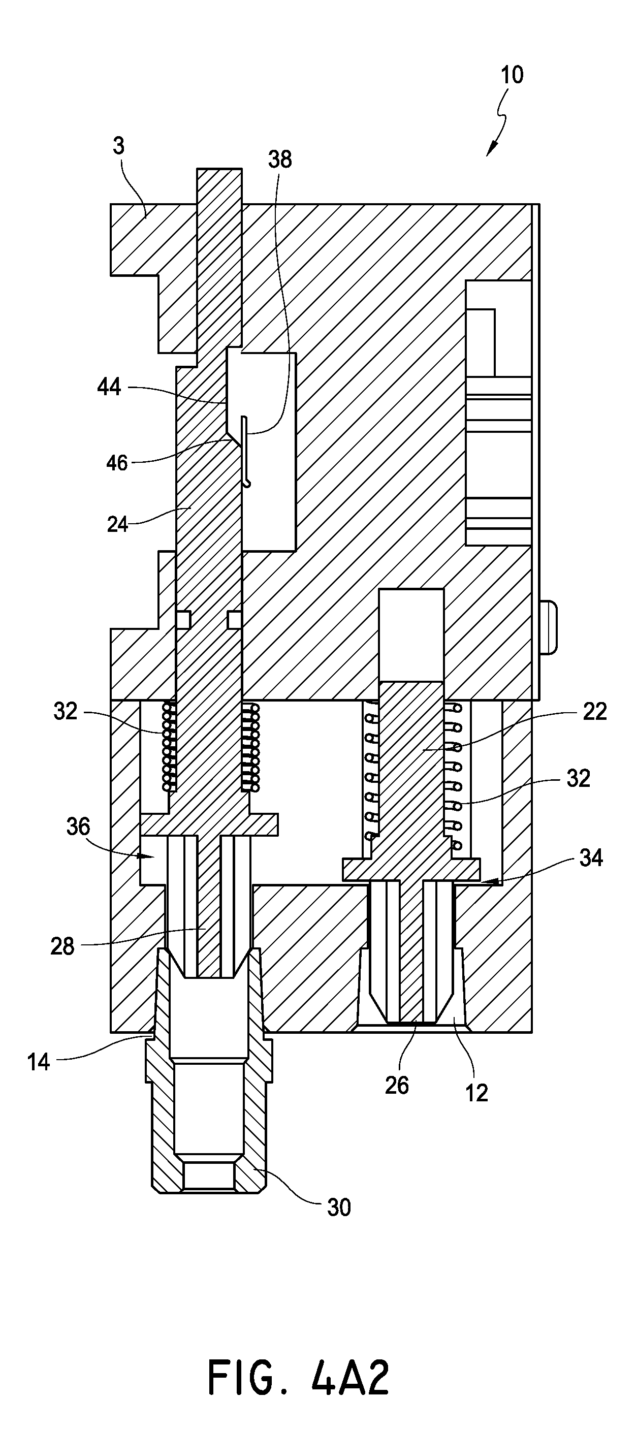
D00013

D00014

D00015

D00016

D00017
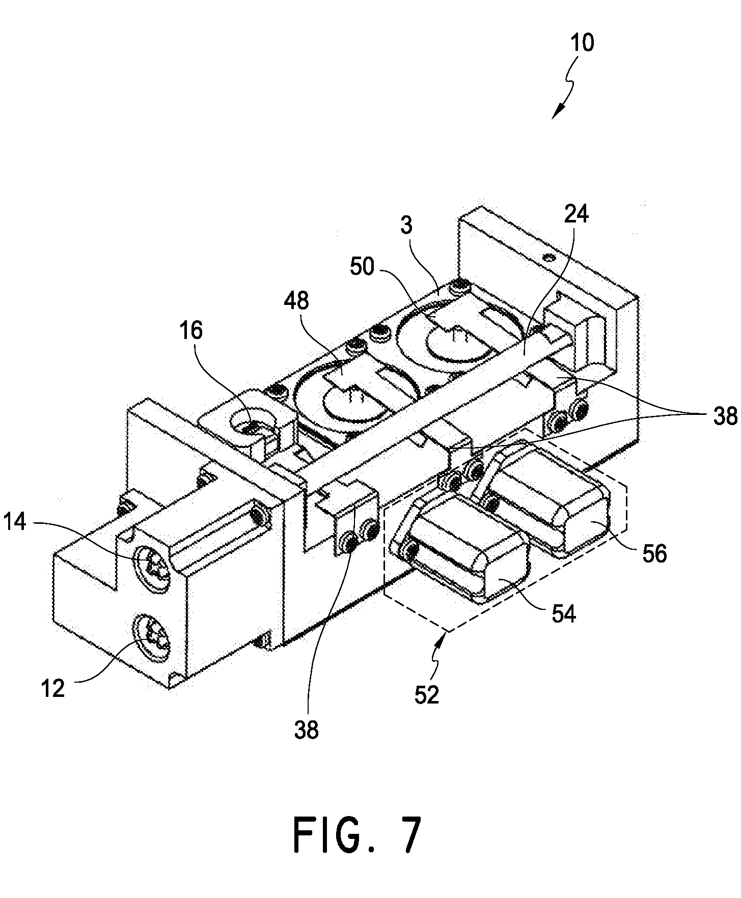
D00018
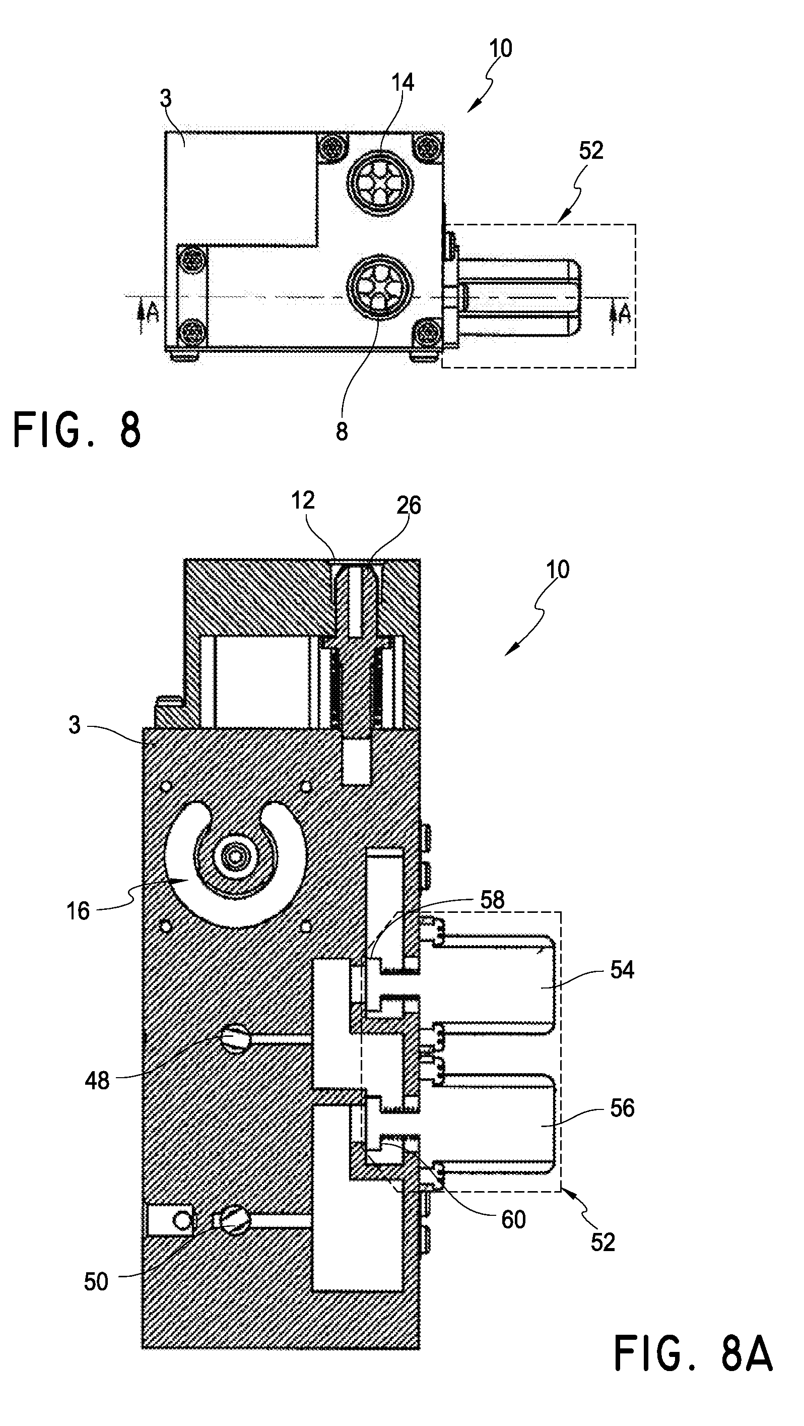
D00019

D00020
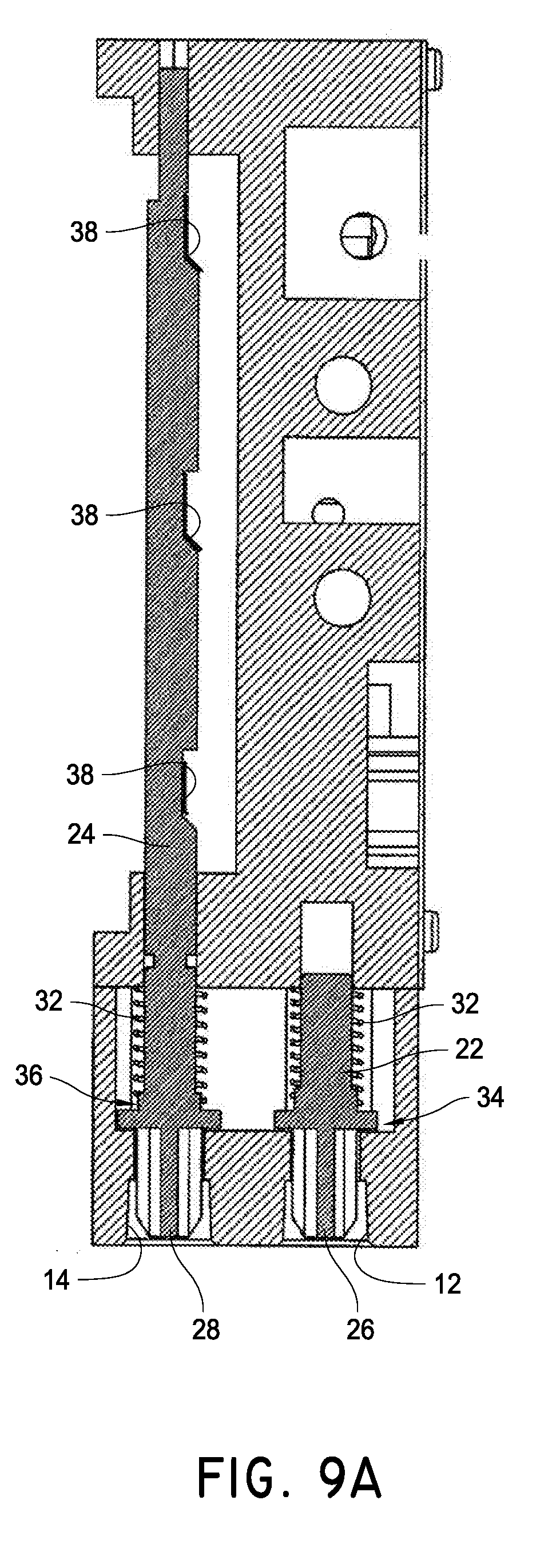
D00021
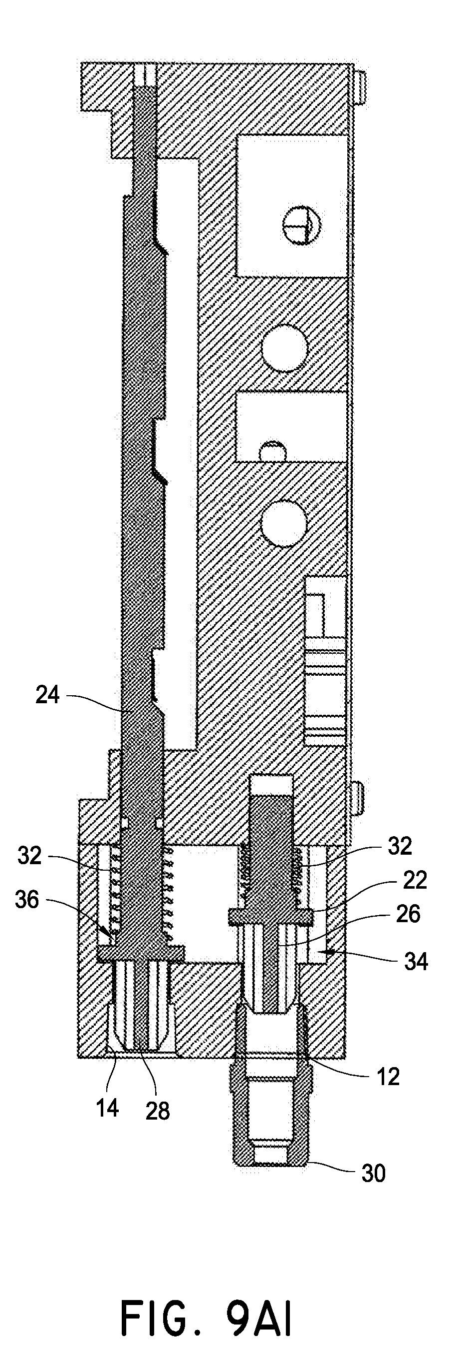
D00022
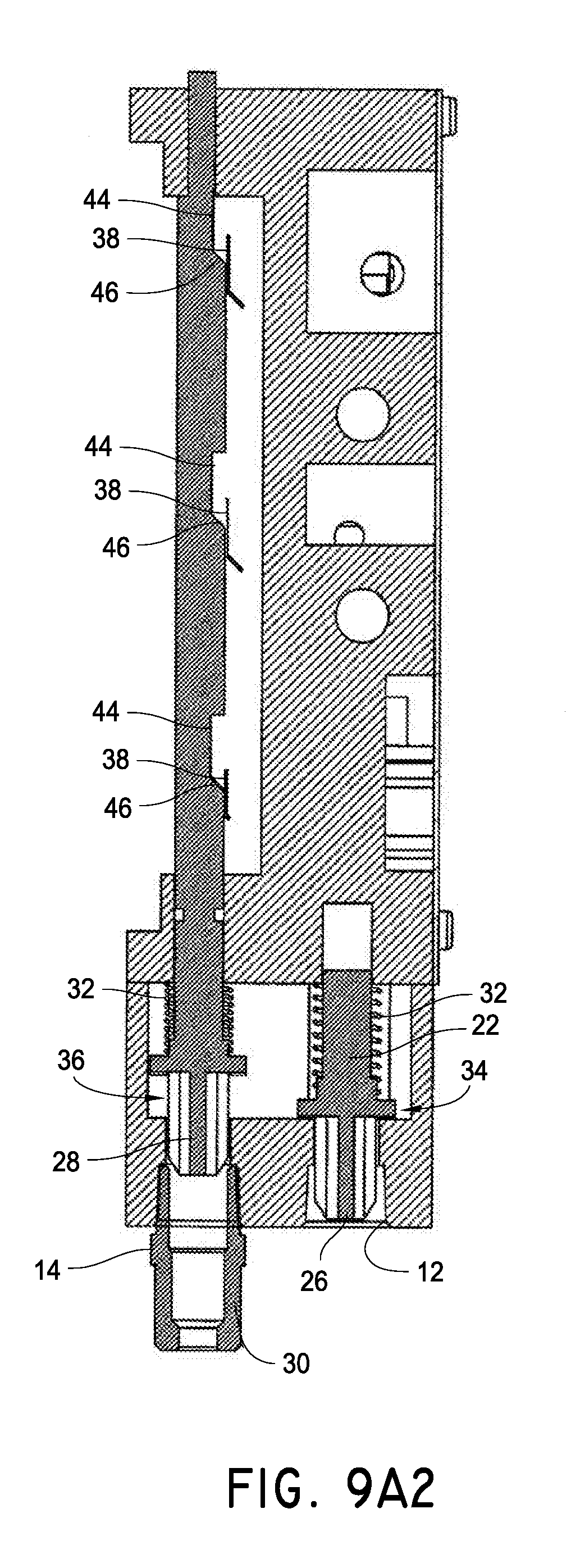
D00023

D00024
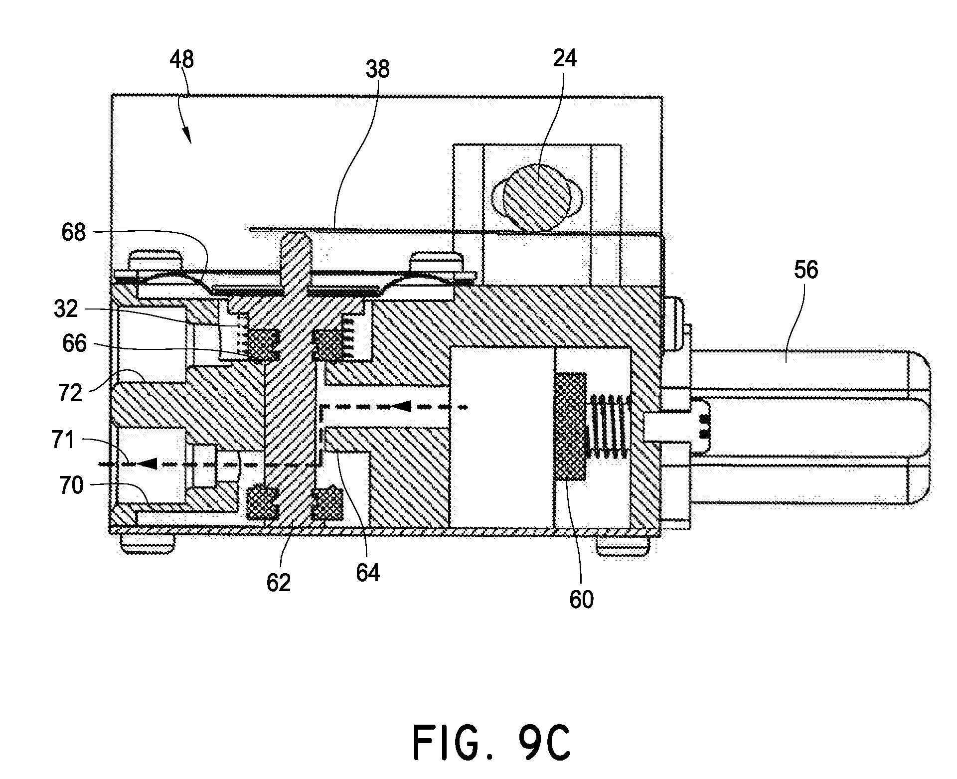
D00025

D00026
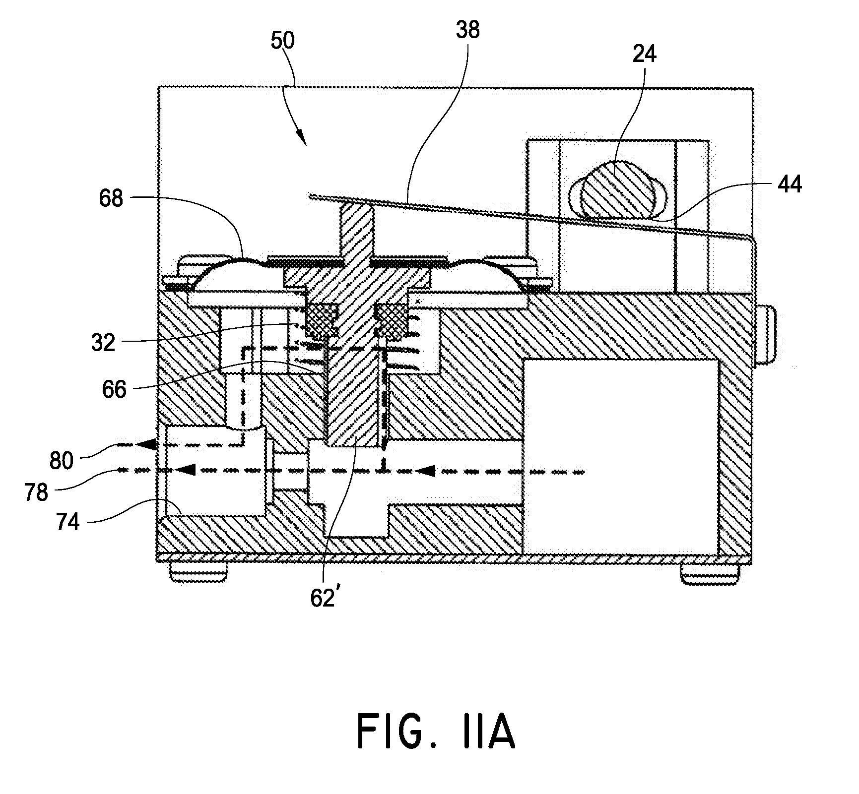
D00027

D00028

D00029
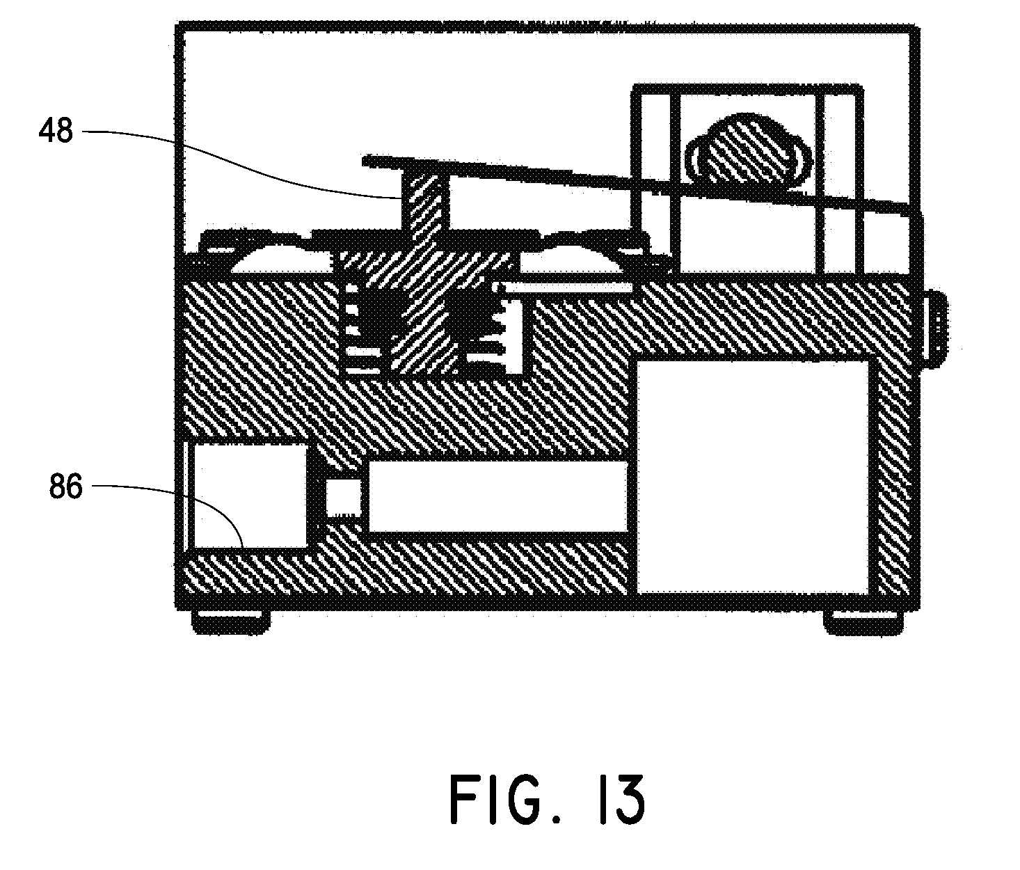
D00030
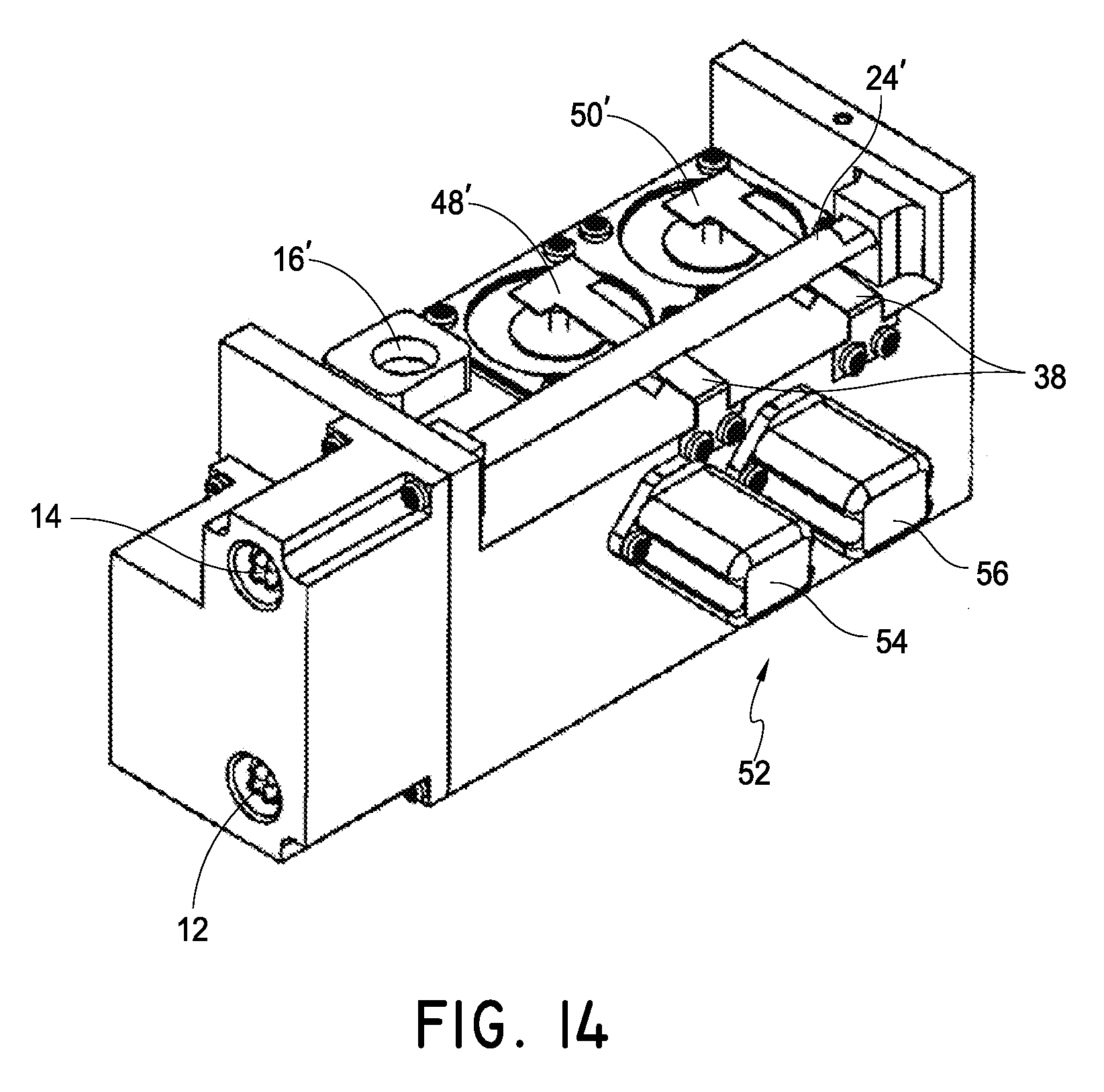
D00031

D00032

D00033
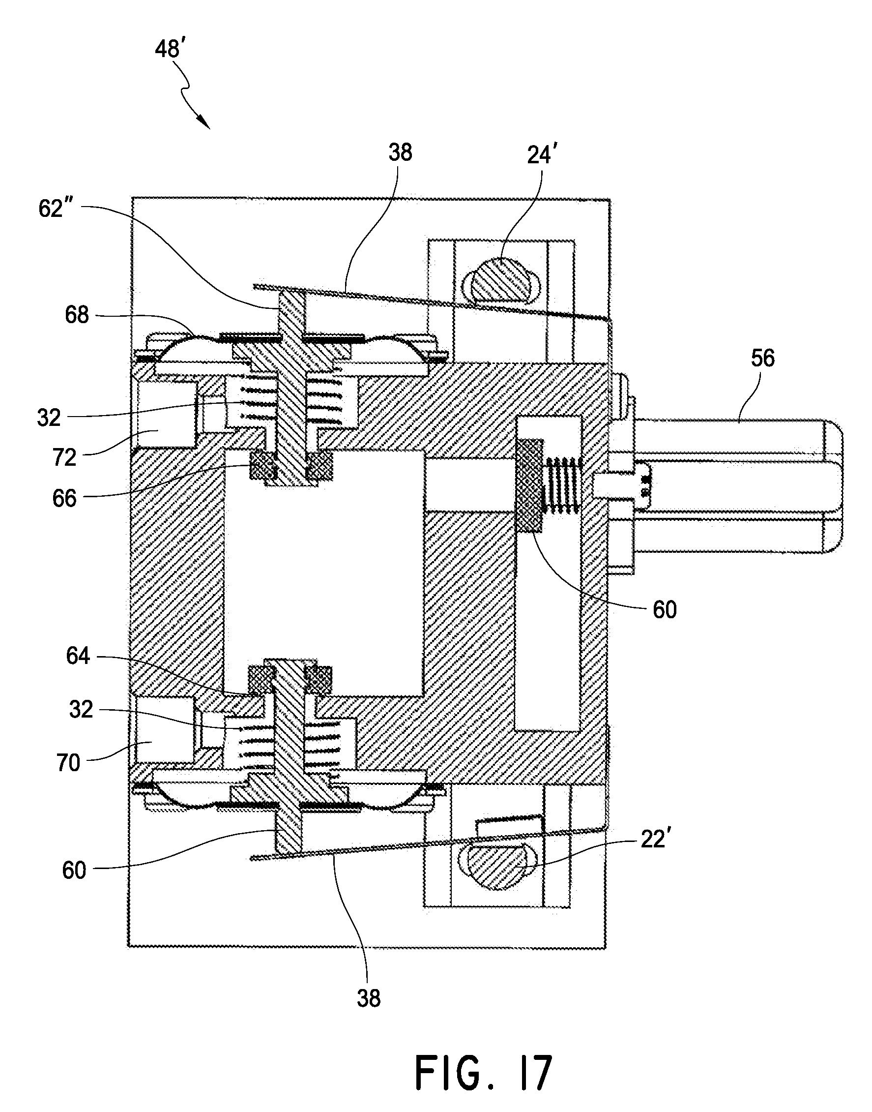
D00034

D00035

D00036
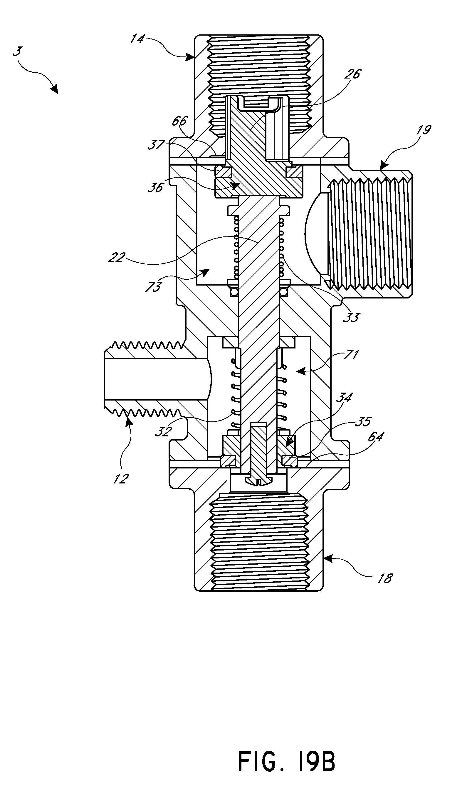
D00037

D00038

D00039

D00040

D00041
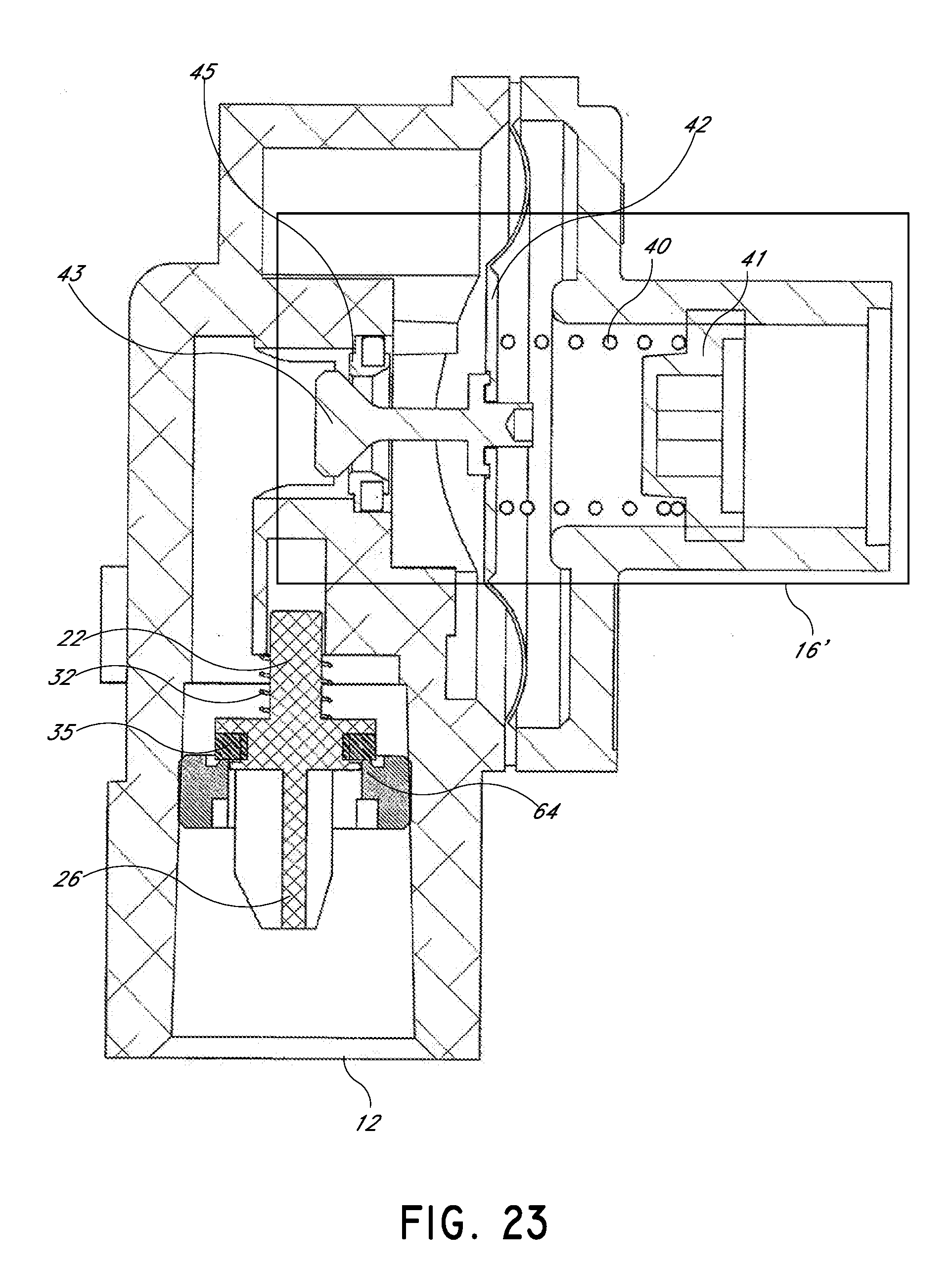
D00042
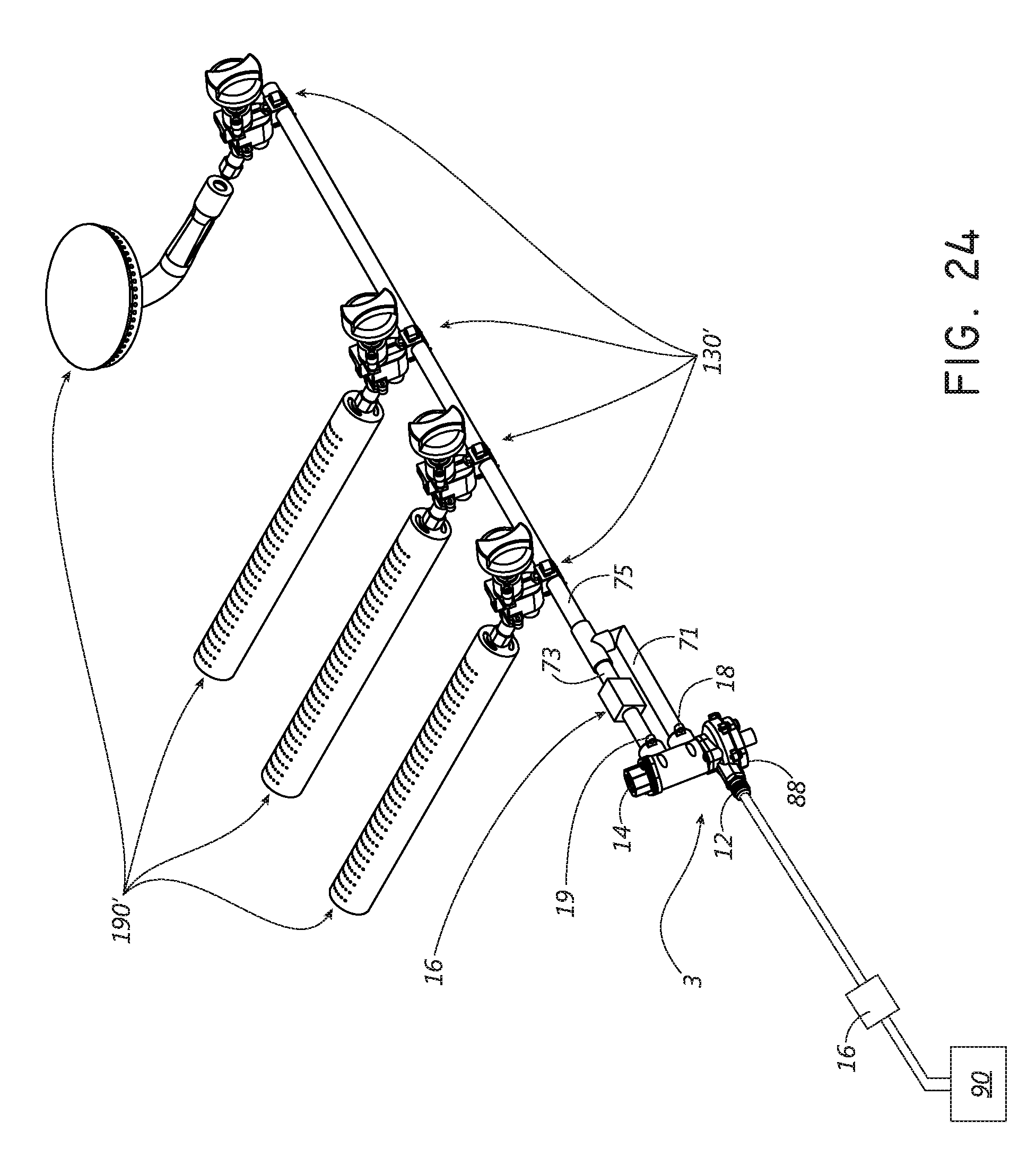
D00043

D00044
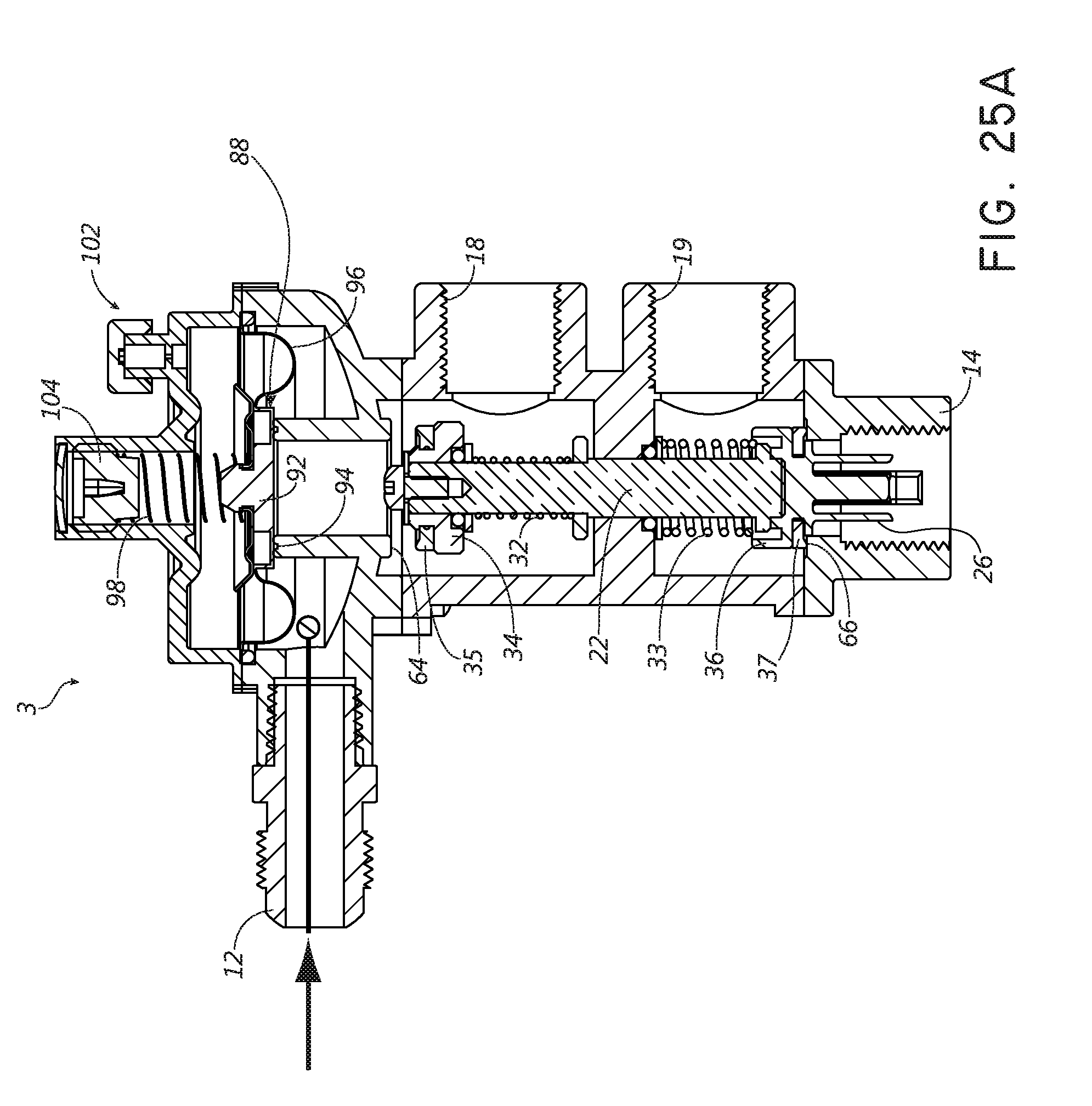
D00045

D00046
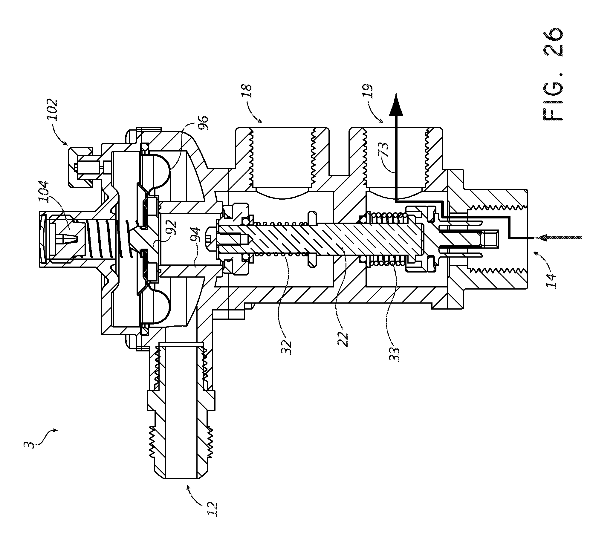
D00047

D00048
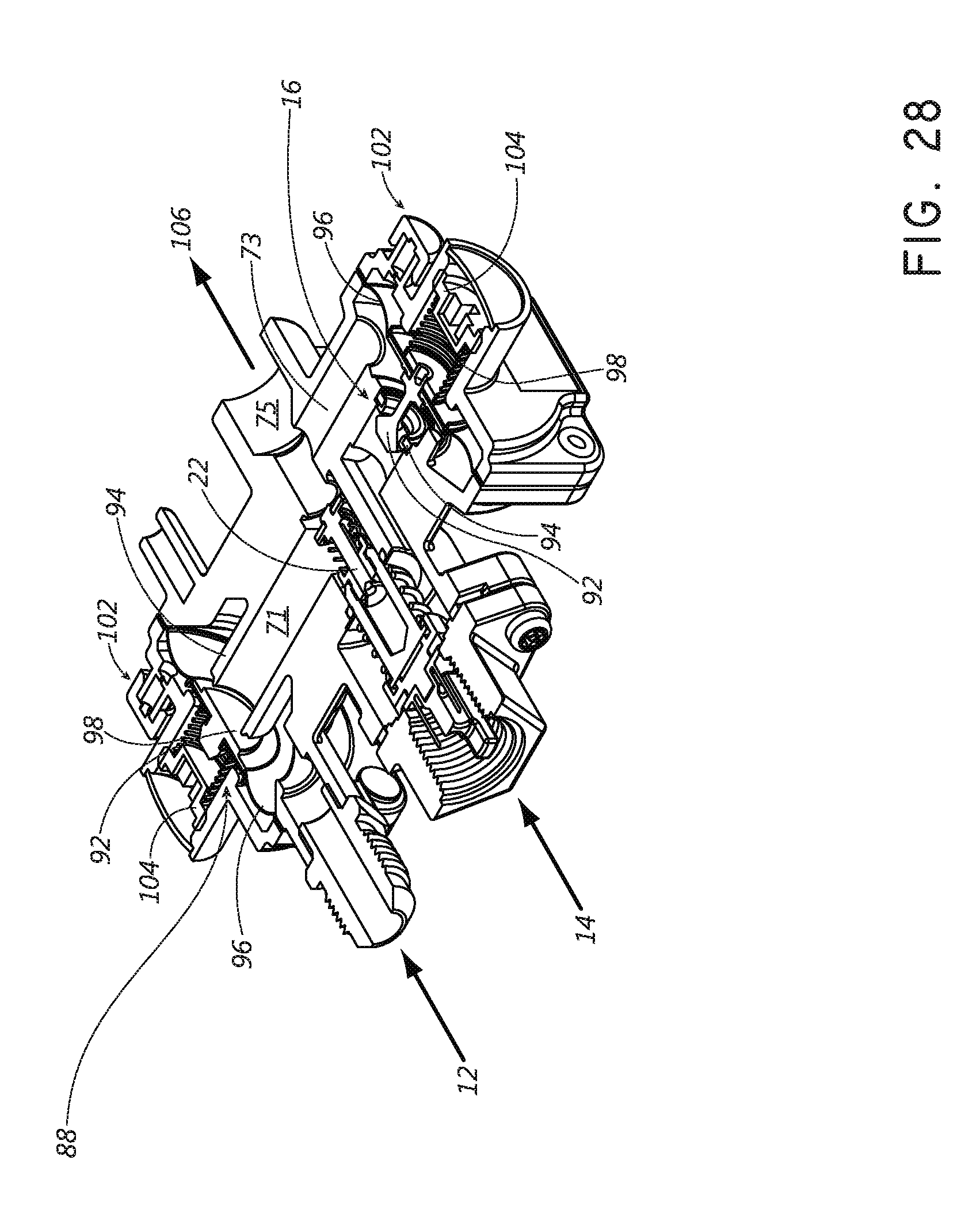
D00049
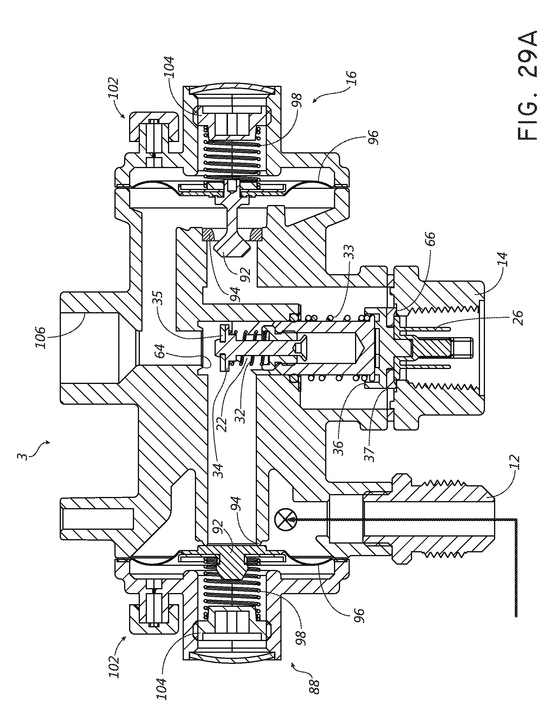
D00050

D00051

D00052

D00053
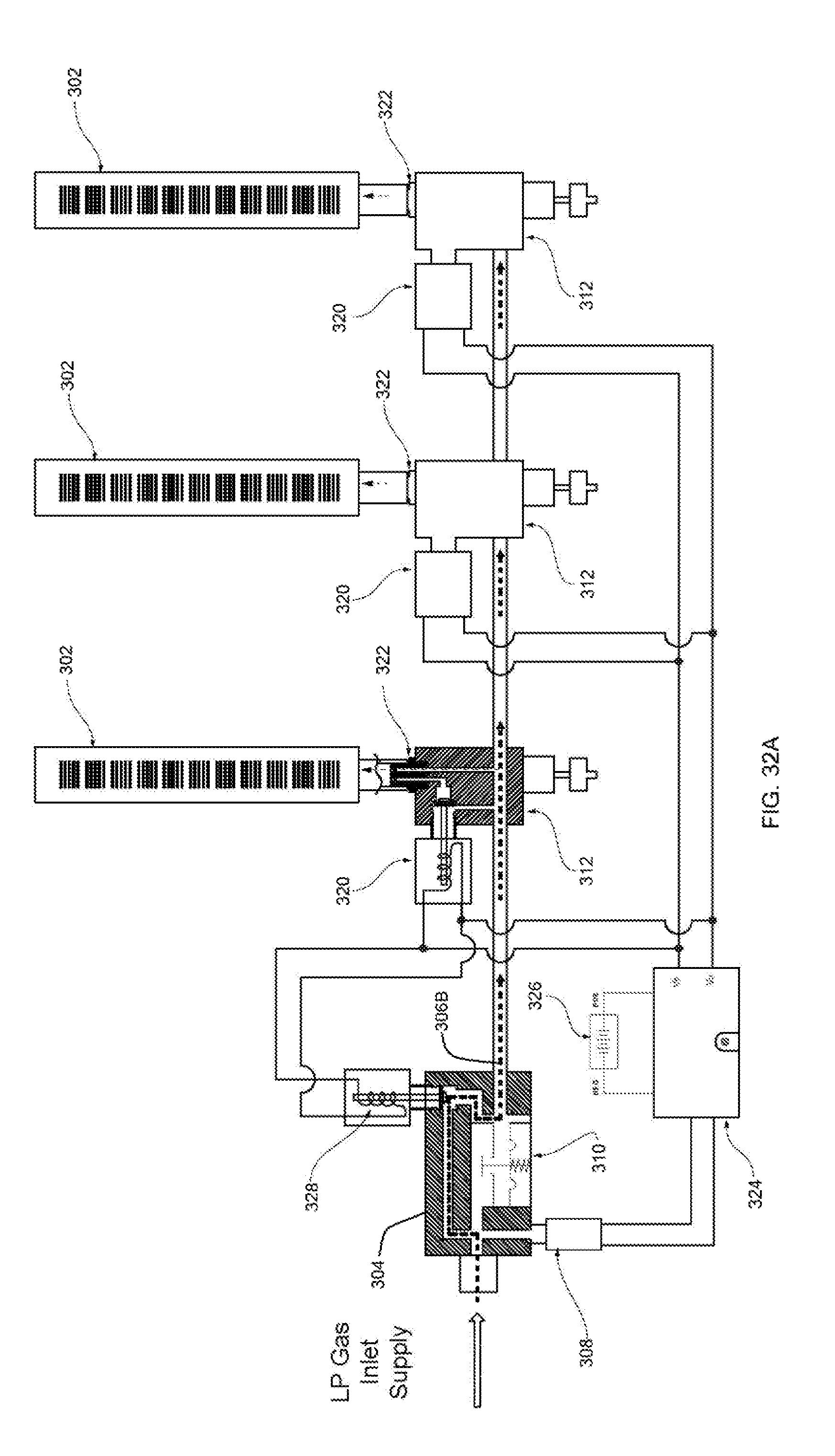
D00054
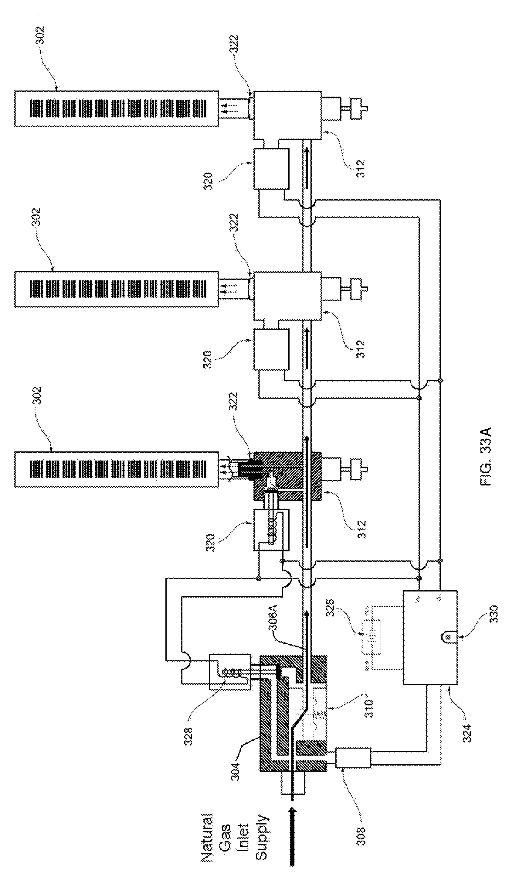
D00055

XML
uspto.report is an independent third-party trademark research tool that is not affiliated, endorsed, or sponsored by the United States Patent and Trademark Office (USPTO) or any other governmental organization. The information provided by uspto.report is based on publicly available data at the time of writing and is intended for informational purposes only.
While we strive to provide accurate and up-to-date information, we do not guarantee the accuracy, completeness, reliability, or suitability of the information displayed on this site. The use of this site is at your own risk. Any reliance you place on such information is therefore strictly at your own risk.
All official trademark data, including owner information, should be verified by visiting the official USPTO website at www.uspto.gov. This site is not intended to replace professional legal advice and should not be used as a substitute for consulting with a legal professional who is knowledgeable about trademark law.