Sensor System
MORIHIRO; Kinji
U.S. patent application number 16/170444 was filed with the patent office on 2019-05-09 for sensor system. This patent application is currently assigned to TOYOTA JIDOSHA KABUSHIKI KAISHA. The applicant listed for this patent is TOYOTA JIDOSHA KABUSHIKI KAISHA. Invention is credited to Kinji MORIHIRO.
| Application Number | 20190136738 16/170444 |
| Document ID | / |
| Family ID | 66328390 |
| Filed Date | 2019-05-09 |


| United States Patent Application | 20190136738 |
| Kind Code | A1 |
| MORIHIRO; Kinji | May 9, 2019 |
SENSOR SYSTEM
Abstract
A sensor system includes: a controller configured to: predict a temperature of exhaust gas of an internal combustion engine in a position in which an exhaust gas sensor having a sensor element is arranged; and control a heater so as to make a temperature of the sensor element close to a target temperature included in a predetermined range, wherein in cases where the predicted temperature of the exhaust gas is higher than a reference temperature, the controller is configured to make the target temperature lower when the predicted temperature is high than when it is low, within a range lower than the reference temperature, whereas in cases where the predicted temperature is lower than the reference temperature, the controller is configured to make the target temperature lower when the predicted temperature is high than when it is low, within a range higher than the reference temperature.
| Inventors: | MORIHIRO; Kinji; (Susono-shi, JP) | ||||||||||
| Applicant: |
|
||||||||||
|---|---|---|---|---|---|---|---|---|---|---|---|
| Assignee: | TOYOTA JIDOSHA KABUSHIKI
KAISHA Toyota-shi JP |
||||||||||
| Family ID: | 66328390 | ||||||||||
| Appl. No.: | 16/170444 | ||||||||||
| Filed: | October 25, 2018 |
| Current U.S. Class: | 1/1 |
| Current CPC Class: | F01N 13/008 20130101; F01N 2560/20 20130101; F01N 2900/1404 20130101; F01N 2560/06 20130101; F01N 2900/1411 20130101; F01N 2900/1602 20130101; F01N 11/00 20130101; F01N 11/005 20130101 |
| International Class: | F01N 11/00 20060101 F01N011/00; F01N 13/00 20060101 F01N013/00 |
Foreign Application Data
| Date | Code | Application Number |
|---|---|---|
| Nov 7, 2017 | JP | 2017-214657 |
Claims
1. A sensor system comprising: an exhaust gas sensor that is arranged in an exhaust passage of an internal combustion engine, and is provided with a sensor element and a heater configured to heat said sensor element; and a controller configured to: predict a temperature of exhaust gas of said internal combustion engine in a position in which said exhaust gas sensor is arranged; and control said heater so as to make a temperature of said sensor element close to a target temperature included in a predetermined range, wherein in cases where a prediction temperature, which is the temperature of the exhaust gas predicted by said controller, is higher than a reference temperature included in said predetermined range, said controller is configured to make said target temperature lower when said prediction temperature is high than when it is low, within a range lower than said reference temperature, whereas in cases where said prediction temperature is lower than said reference temperature, said controller is configured to make said target temperature lower when said prediction temperature is high than when it is low, within a range higher than said reference temperature.
2. The sensor system as set forth in claim 1, wherein said controller is further configured to: predict, based on an operating state of said internal combustion engine, a flow rate of the exhaust gas of said internal combustion engine in a position in which said exhaust gas sensor is arranged; and make an amount of deviation of said target temperature from said reference temperature larger when the flow rate of the exhaust gas predicted by said controller is large than when it is small.
3. The sensor system as set forth in claim 1, further comprising: an accelerator opening sensor that detects an accelerator opening degree; wherein said controller is further configured to predict said temperature of the exhaust gas based on the accelerator opening degree detected by said accelerator opening sensor.
4. The sensor system as set forth in claim 2, further comprising: an accelerator opening sensor that detects an accelerator opening degree; wherein said controller is further configured to predict said flow rate of the exhaust gas based on the accelerator opening degree detected by said accelerator opening sensor.
5. The sensor system as set forth in claim 1, wherein said controller is further configured to provide an upper limit on a rate of change at the time of changing said target temperature.
6. A sensor system comprising: an exhaust gas sensor that is arranged in an exhaust passage of an internal combustion engine, and is provided with a sensor element and a heater configured to heat said sensor element; an accelerator opening sensor that detects an accelerator opening degree; and a controller configured to control said heater so as to make a temperature of said sensor element close to a target temperature included in a predetermined range; wherein in cases where said accelerator opening degree is such that the temperature of the exhaust gas in the surrounding of said exhaust gas sensor becomes higher than a reference temperature included in said predetermined range, said controller is configured to make said target temperature lower when said accelerator opening degree is large than when it is small, within a range lower than said reference temperature, whereas in cases where said accelerator opening degree is such that the temperature of the exhaust gas in the surrounding of said exhaust gas sensor becomes lower than said reference temperature, said controller is configured to make said target temperature lower when said accelerator opening degree is large than when it is small, within a range higher than said reference temperature.
Description
CROSS REFERENCE TO RELATED APPLICATIONS
[0001] This application claims priority to Japanese Patent Application No. 2017-214657 filed on Nov. 7, 2017 the entire contents of which are incorporated by reference herein.
TECHNICAL FIELD
[0002] The present disclosure relates to a sensor system.
BACKGROUND ART
[0003] Some of sensors for detecting components contained in exhaust gas of an internal combustion engine are provided with a heater for heating a sensor element. For example, in an air fuel ratio sensor, a detected value of the sensor changes with the temperature of a sensor element even in the case of the same air fuel ratio, and hence, detection accuracy of the air fuel ratio is maintained by controlling the heater in such a manner that the temperature of the sensor element falls within a predetermined range. In addition, there has been known a technology in which the temperature of a sensor element is adjusted within a predetermined range, in order to change the detection sensitivity of the sensor element with respect to specific exhaust gas components (e.g., NOx, HC, CO) (refer to patent literature 1, for example). With the technology described in patent literature 1, at the time when an internal combustion engine is operated at a lean air fuel ratio at which NOx tends to be generated under high load, etc., the temperature of the sensor element is raised so as to increase its reactivity with respect to NOx, whereas at the time when the internal combustion engine is operated at a rich air fuel ratio at which HC and CO tend to be generated under low load, etc., the temperature of the sensor element is lowered so as to increase its reactivity with respect to HC, CO.
CITATION LIST
Patent Literature
[0004] Patent Literature 1: Japanese patent application laid-open publication No. 2003-314350
SUMMARY
Technical Problem
[0005] Even if the temperature of the sensor element is adjusted by a heater to fall within the predetermined range in order to maintain the detection accuracy of the sensor, for example, in cases where the internal combustion engine is operated at high load, the temperature of the exhaust gas is high, so the sensor element receives heat from the exhaust gas, and the temperature of the sensor element goes up, without being heated by the heater. As a result, when the sensor element is further heated to raise its temperature by means of the heater, the temperature of the sensor element will become excessively high, and may be deviated from the predetermined range. That is, there is a fear that the detection accuracy of the sensor will drop.
[0006] The present disclosure has been made in view of the problems as mentioned above, and the object of the disclosure is to maintain the temperature of a sensor element in a suitable range.
Solution to Problem
[0007] One aspect of the present disclosure resides in a sensor system which comprises: an exhaust gas sensor that is arranged in an exhaust passage of an internal combustion engine, and is provided with a sensor element and a heater configured to heat said sensor element; a controller configured to: predict a temperature of exhaust gas of said internal combustion engine in a position in which said exhaust gas sensor is arranged; and control said heater so as to make a temperature of said sensor element close to a target temperature included in a predetermined range, wherein in cases where a prediction temperature, which is the temperature of the exhaust gas predicted by said controller, is higher than a reference temperature included in said predetermined range, said controller is configured to make said target temperature lower when said prediction temperature is high than when it is low, within a range lower than said reference temperature, whereas in cases where said prediction temperature is lower than said reference temperature, said controller is configured to make said target temperature lower when said prediction temperature is high than when it is low, within a range higher than said reference temperature.
[0008] The exhaust gas sensor is a sensor which can adjust the temperature of the sensor element by controlling electrical supply to the heater. The temperature of the sensor element can be changed by the heat which is received by the sensor element from the exhaust gas or the heat which is deprived by the exhaust gas from the sensor element, irrespective of the heater. Here, it is considered that the heater is controlled in a feedback manner so that the temperature of the sensor element becomes close to the target temperature, but when the electrical supply to the heater is controlled after the temperature of the sensor element has actually changed, the electrical supply control of the heater will be delayed with respect to the temperature change of the sensor element, giving rise to a fear that the temperature of the sensor element may deviate from the predetermined range. Here, note that the predetermined range is a range of temperature where the detection accuracy of the exhaust gas sensor falls within an allowable range, and it is a range based on a range of activation temperature of the sensor element. Also, note that the predetermined range may be a range equal to the activation range of the sensor element, or may be a range narrower than the activation range in order to provide a margin so that the temperature of the sensor element does not deviate from the activation range. The reference temperature for the temperature of the sensor element may be a temperature at which the detection accuracy of the exhaust gas sensor becomes the highest, or may also be a central temperature of a temperature range in which the detection accuracy of the exhaust gas sensor becomes the highest. In addition, the reference temperature may also be a central temperature of the predetermined range.
[0009] The temperature of the exhaust gas in the surrounding of the exhaust gas sensor can be predicted from an operating state of the internal combustion engine, a heat capacity in an exhaust system from the internal combustion engine to the exhaust gas sensor, etc. That is, the temperature of the exhaust gas flowing out from the internal combustion engine has a correlation with the operating state of the internal combustion engine, and so can be predicted, even before the exhaust gas is actually discharged from the internal combustion engine. In addition, the exhaust gas discharged from the internal combustion engine is deprived of heat by the exhaust system and the temperature of the exhaust gas drops, while flowing through the exhaust system. This amount of temperature drop can also be predicted in advance. Accordingly, even before the exhaust gas of the internal combustion engine reaches an area or vicinity surrounding the exhaust gas sensor, the temperature of the exhaust gas at the time when the exhaust gas reaches the area surrounding the exhaust gas sensor can be predicted. Then, when changing the temperature of the sensor element in advance based on a predicted temperature of the exhaust gas, it is possible to suppress the temperature control of the sensor element from being delayed with respect to a change in the temperature of the exhaust gas. That is, in cases where the predicted temperature of the exhaust gas is higher than the reference temperature, the target temperature of the sensor element is made lower than the reference temperature, whereby the temperature of the sensor element can be made low in advance, even if the temperature of the exhaust gas becomes high. On the other hand, in cases where the predicted temperature of the exhaust gas is lower than the reference temperature, the target temperature of the sensor element is made higher than the reference temperature, whereby the temperature of the sensor element can be made high in advance, even if the temperature of the exhaust gas becomes low. Moreover, the target temperature of the sensor element is made lower when the predicted temperature of the exhaust gas is high than when it is low, whereby the temperature of the sensor element can be made low according to the temperature of the exhaust gas in advance, even if the temperature of the exhaust gas becomes high, whereas the temperature of the sensor element can be made high according to the temperature of the exhaust gas in advance, even if the temperature of the exhaust gas becomes low. In addition, by changing the target temperature within the predetermined range, it is possible to suppress the target temperature from becoming excessively high or excessively low. Accordingly, the temperature of the sensor element can be maintained in a suitable range.
[0010] Further, said controller can predict, based on the operating state of said internal combustion engine, a flow rate of the exhaust gas of said internal combustion engine in a position in which said exhaust gas sensor is arranged, and make an amount of deviation of said target temperature from said reference temperature larger when the flow rate of the exhaust gas predicted by said controller is large than when it is small.
[0011] The flow rate of the exhaust gas in the surrounding of the exhaust gas sensor has a correlation with the operating state of the internal combustion engine, etc., similar to the temperature of the exhaust gas in the surrounding of the exhaust gas sensor, and so can be predicted from the operating state of the internal combustion engine, etc. That is, even before the exhaust gas of the internal combustion engine reaches the exhaust gas sensor, the flow rate of the exhaust gas at the time when the exhaust gas reaches the area surrounding the exhaust gas sensor can be predicted. Here, in cases where the temperature of the exhaust gas is higher than the temperature of the sensor element, the temperature of the sensor element rises more quickly as the flow rate of the exhaust gas is larger. On the other hand, in cases where the temperature of the exhaust gas is lower than the temperature of the sensor element, the temperature of the sensor element falls more quickly as the flow rate of the exhaust gas is larger. That is, the rate of the temperature change of the sensor element becomes larger than when the flow rate of the exhaust gas large than when it is small. Even if the temperature of the exhaust gas is the same and a temperature finally reached by the sensor element is the same, a period of time until the sensor element reaches the final temperature varies with the flow rate of the exhaust gas. In contrast to this, when the target temperature is made to change according to the flow rate of the exhaust gas, the target temperature can be set not only according to the temperature finally reached, but also according to the rate of the temperature change of the sensor element. Even in this case, too, by setting the target temperature within the predetermined range, it is possible to suppress the target temperature from becoming excessively high or excessively low. Here, it is shown that in cases where the amount of deviation of the target temperature from the reference temperature is made larger, when the target temperature is lower than the reference temperature, the target temperature is made further lower, whereas when the target temperature is higher than the reference temperature, the target temperature is further higher.
[0012] Moreover, further provision can be made for an accelerator opening sensor that detects an accelerator opening degree, and said controller can predict the temperature of said exhaust gas based on the accelerator opening degree detected by said accelerator opening sensor.
[0013] Because the operating state of the internal combustion engine changes according to the accelerator opening degree, the operating state of the internal combustion engine and the accelerator opening degree are in correlation with each other. Accordingly, the accelerator opening degree and the temperature of the exhaust gas flowing out from the internal combustion engine are in correlation with each other, so the temperature of the exhaust gas flowing out from the internal combustion engine can be predicted based on the accelerator opening degree. Thus, the temperature of the exhaust gas at the time when this exhaust gas reaches the area surrounding the exhaust gas sensor can also be predicted, as described above. Accordingly, the temperature of the exhaust gas in the surrounding of the exhaust gas sensor can be easily predicted based on the accelerator opening degree.
[0014] Moreover, further provision can be made for an accelerator opening sensor that detects an accelerator opening degree, wherein said controller can predict the flow rate of said exhaust gas based on the accelerator opening degree detected by said accelerator opening sensor.
[0015] The flow rate of the exhaust gas in the surrounding of the exhaust gas sensor also changes with the accelerator opening degree, so the flow rate of the exhaust gas in the surrounding of the exhaust gas sensor can be easily predicted based on the accelerator opening degree.
[0016] Further, said controller can provide an upper limit on a rate of change at the time of changing said target temperature.
[0017] By providing the upper limit on the rate of change of the target temperature, the temperature of the exhaust gas sensor can be suppressed from changing suddenly, thus making it possible to suppress the breakage of the exhaust gas sensor, and the occurrence of a deviation of the detected value.
[0018] In addition, another aspect of the present disclosure resides in a sensor system which comprises: an exhaust gas sensor that is arranged in an exhaust passage of an internal combustion engine, and is provided with a sensor element and a heater configured to heat said sensor element; an accelerator opening sensor that detects an accelerator opening degree; and a controller configured to control said heater so as to make a temperature of said sensor element close to a target temperature included in a predetermined range; wherein in cases where said accelerator opening degree is such that the temperature of the exhaust gas in the surrounding of said exhaust gas sensor becomes higher than a reference temperature included in said predetermined range, said controller is configured to make said target temperature lower when said accelerator opening degree is large than when it is small, within a range lower than said reference temperature, whereas in cases where said accelerator opening degree is such that the temperature of the exhaust gas in the surrounding of said exhaust gas sensor becomes lower than said reference temperature, said controller is configured to make said target temperature lower when said accelerator opening degree is large than when it is small, within a range higher than said reference temperature.
[0019] As described above, the accelerator opening degree and a future temperature of the exhaust gas in the surrounding of the exhaust gas sensor are in correlation with each other, so the target temperature of the sensor element can also be directly set based on the accelerator opening degree, without predicting the future temperature of the exhaust gas in the surrounding of the exhaust gas sensor.
Advantageous Effects
[0020] According to the present disclosure, the temperature of a sensor element can be maintained in a suitable range.
BRIEF DESCRIPTION OF DRAWINGS
[0021] FIG. 1 is a view showing the schematic construction of an internal combustion engine as well as its intake and exhaust systems according to an embodiment of the present disclosure.
[0022] FIG. 2 is a cross sectional view of an air fuel ratio sensor.
[0023] FIG. 3 is a view showing a relation between a temperature of exhaust gas ET in the surrounding of the air fuel ratio sensor to be predicted, and an offset amount (a target offset amount) of a target temperature of a sensor element from a reference temperature.
[0024] FIG. 4 is a view for correcting the target offset amount shown in FIG. 3.
[0025] FIG. 5 is a time chart showing the changes over time of a variety of kinds of values in the case of setting the target temperature of the sensor element constant at the reference temperature.
[0026] FIG. 6 is a time chart showing the changes over time of a variety of kinds of values in cases where sensor element impedance control according to a first embodiment is carried out.
[0027] FIG. 7 is a flow chart showing a flow for setting a duty ratio in the sensor element impedance control according to the first embodiment.
[0028] FIG. 8 is a flow chart showing a flow for setting a duty ratio in the sensor element impedance control according to the first embodiment, in cases where a flow rate of exhaust gas is not taken into consideration.
[0029] FIG. 9 is a flow chart showing a flow for setting a duty ratio in sensor element impedance control according to a second embodiment.
DESCRIPTION OF THE EMBODIMENTS
[0030] Hereinafter, embodiments carrying out the present disclosure will be described in detail by way of example with reference to the attached drawings. However, the dimensions, materials, shapes, relative arrangements and so on of component parts described in the embodiments are not intended to limit the scope of the present disclosure to these alone in particular as long as there are no specific statements.
First Embodiment
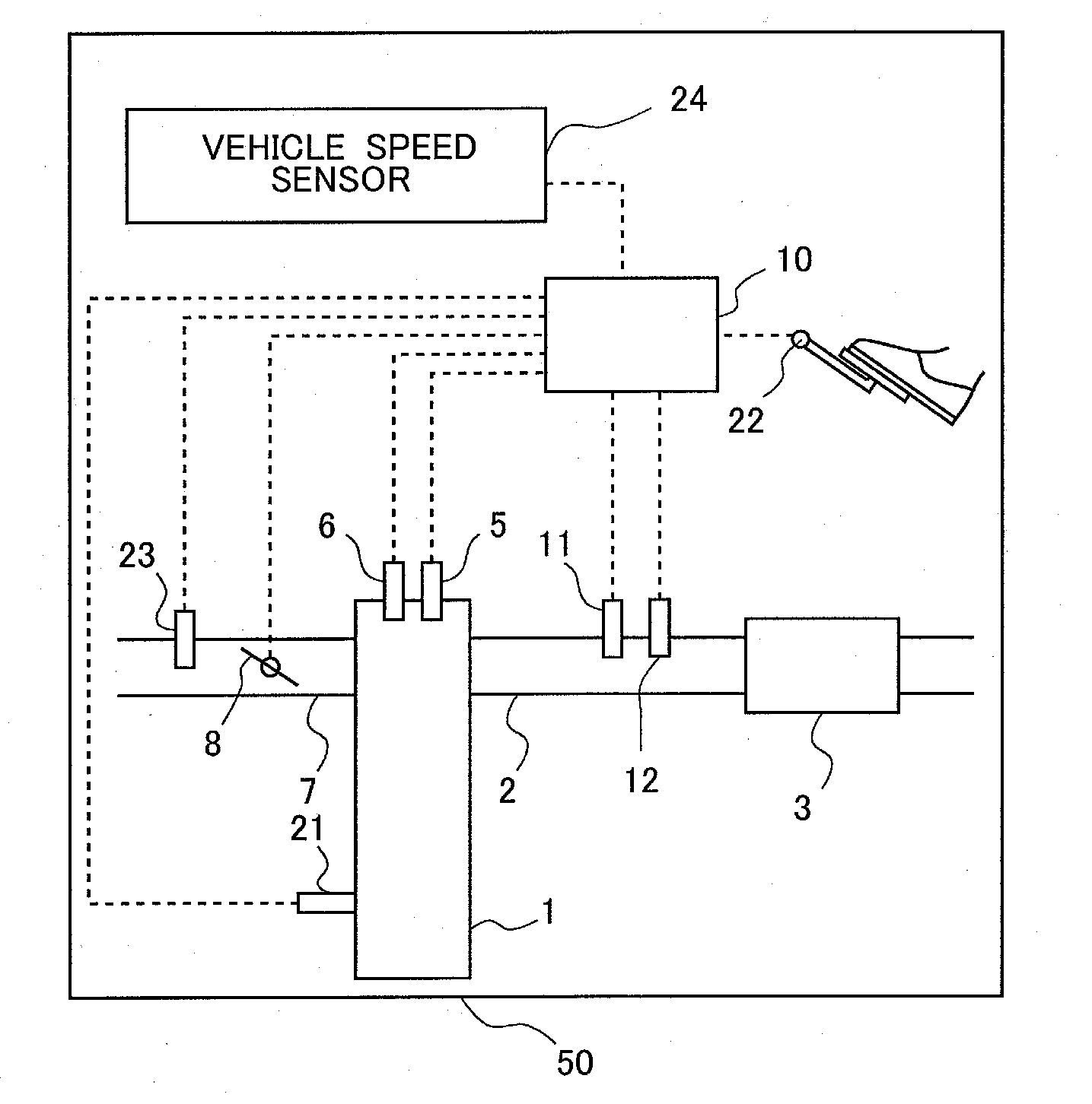
[0031] FIG. 1 is a view showing the schematic construction of an internal combustion engine 1 as well as its intake and exhaust systems according to a first embodiment of the present disclosure. The internal combustion engine 1 is a gasoline engine mounted on a vehicle 50. Here, note that this embodiment is also able to be applied to a diesel engine. An exhaust passage 2 is connected to the internal combustion engine 1. Although a catalyst 3 is arranged in the exhaust passage 2, this catalyst 3 is not an indispensable construction.
[0032] Further, in the exhaust passage 2 at a location upstream of the catalyst 3, there are arranged an air fuel ratio sensor 11 that detects an air fuel ratio of exhaust gas flowing into the catalyst 3, and a temperature sensor 12 that detects a temperature of the exhaust gas flowing into the catalyst 3. This air fuel ratio sensor 11 is, for example, a limiting current type oxygen sensor, and generates an output which is substantially proportional to the air fuel ratio over a wide air fuel ratio range. Here, note that the air fuel ratio sensor 11 is not limited to the limiting current type oxygen sensor, but may also be an electromotive force type (concentration cell type) oxygen sensor, for example. Also, note that in this embodiment, the air fuel ratio sensor 11 corresponds to an exhaust gas sensor in the present disclosure.
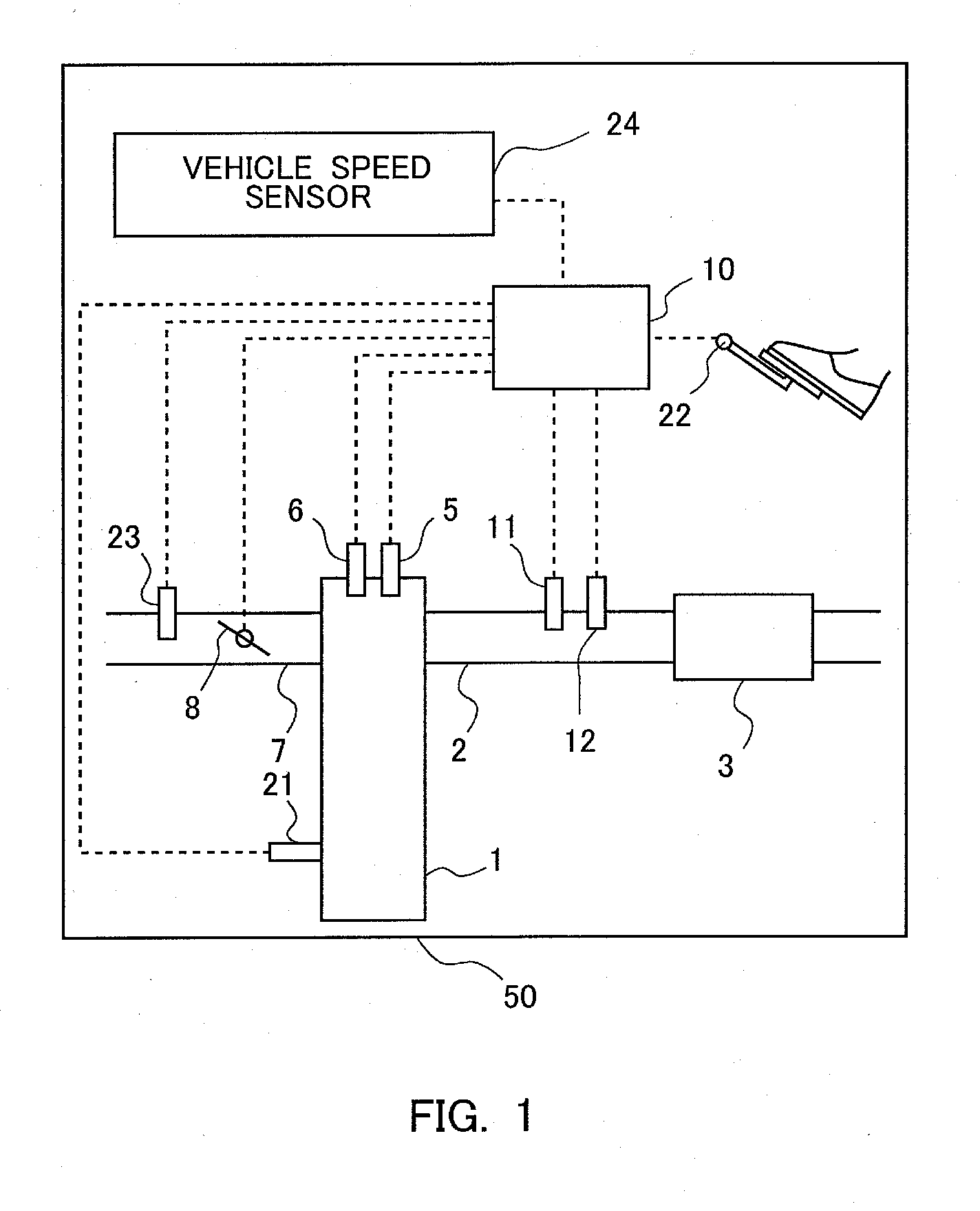
[0033] FIG. 2 is a cross sectional view of the air fuel ratio sensor 11. The air fuel ratio sensor 11 includes a sensor element 11A which generates an output corresponding to the air fuel ratio (or this may also be an oxygen concentration) of the exhaust gas, and a heater 11B which heats this sensor element 11A. The sensor element 11A includes a solid electrolyte layer 101, an A-chamber side electrode 102, a B-chamber side electrode 103, and a diffusion rate controlling layer 104. The solid electrolyte layer 101 serves to separate an A-chamber leading to the atmosphere and a B-chamber leading to the interior of the exhaust passage 2 from each other. The solid electrolyte layer 101 is composed of a porous insulating material such as zirconia (Zr.sub.2O.sub.3). The A-chamber side electrode 102, which is composed of platinum, is arranged on an A-chamber side wall surface of the solid electrolyte layer 101, and the B-chamber side electrode 103, which is composed of platinum, is arranged on a B-chamber side wall surface of the solid electrolyte layer 101. A surface of the B-chamber side electrode 103 is covered with the diffusion rate controlling layer 104, and a part of exhaust gas flowing through the exhaust passage 2 passes through the interior of the diffusion rate controlling layer 104, and comes into contact with the B-chamber side electrode 103. In addition, the heater 11B is arranged in the A-chamber side in a state where it is sandwiched between insulating substrates 105.
[0034] In the air fuel ratio sensor 11 of such a construction, when a predetermined voltage is applied between the A-chamber side electrode 102 and the B-chamber side electrode 103, an electric current of a magnitude corresponding to a concentration of oxygen in the exhaust gas will flow into the air fuel ratio sensor 11 by the application of this voltage. Because this electric current has a correlation with the air fuel ratio, the air fuel ratio sensor 11 detects the air fuel ratio based on this electric current.
[0035] In addition, on each of cylinders of the internal combustion engine 1, there are mounted a spark plug 5 for generating an electric spark, and a fuel injection valve 6 for injecting fuel into a corresponding cylinder. Moreover, an intake passage 7 is connected to the internal combustion engine 1. In the intake passage 7, there are arranged an air flow meter 23 and a throttle valve 8. The air flow meter 23 is a sensor which serves to detect an amount of intake air sucked into the internal combustion engine 1. The throttle valve 8 serves to adjust the amount of intake air sucked into the internal combustion engine 1.
[0036] Then, an ECU 10, which is an electronic controller, is provided as a control device (controller) in combination with the internal combustion engine 1. A program for controlling the internal combustion engine 1, an exhaust gas purification apparatus, etc., is stored in the ECU 10, so that the ECU 10 controls the internal combustion engine 1, the exhaust gas purification apparatus, etc., according to this program. A crank position sensor 21, which outputs a signal corresponding to the rotational speed of the internal combustion engine 1, an accelerator opening sensor 22, which outputs a signal corresponding to the degree of opening of an accelerator pedal (an accelerator opening degree), and a vehicle speed sensor 24, which outputs a signal corresponding to the travel speed of the vehicle 50, in addition to the above-mentioned various kinds of sensors, etc., are electrically connected to the ECU 10, so that the output values (or signals) of these individual sensors are passed or transmitted to the ECU 10.
[0037] Accordingly, the ECU 10 can grasp an operating state of the internal combustion engine 1, such as an engine rotational speed based on the detection of the crank position sensor 21, an engine load factor based on the detection of the accelerator opening sensor 22, etc. On the other hand, the spark plugs 5, the fuel injection valves 6, the throttle valve 8 and the heater 11B are connected to the ECU 10 through electrical wiring, so that these parts are controlled by means of the ECU 10. That is, ignition timing, a fuel injection amount, fuel injection timing, a throttle opening degree, and the temperature of the heater 11B are controlled by the ECU 10.
[0038] The ECU 10 sets a target torque with respect to the internal combustion engine 1 based on the accelerator opening degree detected by the accelerator opening sensor 22. Here, note that the relation between the accelerator opening degree and the target torque has been obtained in advance by experiments, simulations or the like, and stored in the ECU 10. Then, the ECU 10 controls the internal combustion engine 1 so that the target torque is achieved (i.e., the torque of the internal combustion engine 1 becomes the target torque). Such control is referred to as torque demand control. This torque demand control is well-known control, and is to carry out the opening degree control of the throttle valve 8 and the ignition timing control of the spark plug 5, etc., in order to achieve the target torque. In other words, a target throttle opening degree is calculated based on the target torque, and ignition timing necessary to achieve the target torque with an amount of intake air at the target throttle opening degree is calculated. That is, a torque, which will be obtained if the ignition timing is set to an optimum ignition timing (MBT (Minimum Advance for Best Torque)) with the above-mentioned amount of intake air, is estimated, and an amount of retardation of the ignition timing (an amount of retardation from the MBT) is calculated according to the ratio of the target torque with respect to the torque thus estimated, whereby the opening degree control of the throttle valve 8 and the ignition timing control of the spark plug 5 are carried out so as to obtain the target throttle opening degree and the amount of retardation of the ignition timing (target ignition timing) thus calculated, thereby controlling the torque of the internal combustion engine 1 so as to become the target torque. Here, note that in the torque demand control, the ECU 10 calculates a future engine rotational speed and a future engine load factor based on the accelerator opening degree.
[0039] Moreover, the ECU 10 controls the amount of fuel injection or the throttle opening degree in a feedback manner so that the air fuel ratio (detection air fuel ratio) detected by the air fuel ratio sensor 11 becomes the target air fuel ratio. This control is referred to as air fuel ratio feedback control.
[0040] Further, the ECU 10 controls the heater 11B in such a manner that the temperature of the sensor element 11A falls within a predetermined range, in order to maintain the detection accuracy of the air fuel ratio sensor 11. When the temperature of the sensor element 11A deviates from this predetermined range, the correlation between the detected value of the air fuel ratio sensor 11 and the actual air fuel ratio will change, so the detection accuracy of the air fuel ratio by the air fuel ratio sensor 11 becomes low. This predetermined range is set to a range of temperature in which the sensor element 11A is activated (e.g., a range from 650 degrees C. to 750 degrees C.). In this case, the temperature of the sensor element 11A can be represented by an impedance of the sensor element 11A. That is, there is the following relation: as the temperature of the sensor element 11A becomes higher, the impedance thereof becomes smaller. In this embodiment, a target impedance indicating the target temperature is set, and an actual impedance indicating an actual temperature of the sensor element 11A is detected, wherein the ECU 10 controls the output of the heater 11B in a feedback manner so that the actual impedance becomes equal to the target impedance. This control is referred to as sensor element impedance control. Here, note that the sensor element impedance control in this embodiment is an example of the temperature control of the sensor element 11A, and the temperature control of the sensor element 11A may be carried out by other control.
[0041] In the sensor element impedance control, the ECU 10 sets the target temperature (target impedance) so that even if the air fuel ratio sensor 11 receives heat from the exhaust gas or heat is taken from the air fuel ratio sensor 11 by the exhaust gas, the temperature of the sensor element 11A of the air fuel ratio sensor 11 falls within the predetermined range, and the ECU 10 carries out duty control of the heater 11B so that the temperature of the sensor element 11A becomes equal to the target temperature.
[0042] The temperature of the sensor element 11A is adjusted by the sensor element impedance control. However, when the engine load factor becomes high, the temperature of the exhaust gas becomes high, so the temperature of the sensor element 11A may be raised by the heat received from this exhaust gas of high temperature. In this case, the temperature of the sensor element 11A rises irrespective of the sensor element impedance control, and hence, there is a fear that the temperature of the sensor element 11A may become higher than an upper limit of the predetermined range. On the other hand, when the engine load factor becomes low, the temperature of the exhaust gas becomes low, so the temperature of the sensor element 11A may be lowered by the heat deprived by this exhaust gas of low temperature. In this case, the temperature of the sensor element 11A is raised by means of the sensor element impedance control, but in cases where the amount of heat deprived by the exhaust gas is large, there is a fear that the temperature of the sensor element 11A may become lower than a lower limit of the predetermined range.
[0043] Accordingly, the ECU 10 adjusts the temperature of the sensor element 11A in advance based on the temperature (prediction temperature) of the exhaust gas predicted in the surrounding of the air fuel ratio sensor 11. That is, in cases where the temperature of the exhaust gas passing in future through the surrounding of the air fuel ratio sensor 11 is lower than the temperature of the sensor element 11A so that the temperature of the sensor element 11A may drop, the temperature of the sensor element 11A is raised in advance before the exhaust gas of low temperature actually lowers the temperature of the sensor element 11A. At this time, the target temperature in the sensor element impedance control is made high. On the other hand, in cases where the temperature of the exhaust gas passing in future through the surrounding of the air fuel ratio sensor 11 is higher than the temperature of the sensor element 11A so that the temperature of the sensor element 11A may rise, the temperature of the sensor element 11A is lowered in advance before the exhaust gas of high temperature actually raises the temperature of the sensor element 11A.
[0044] The prediction of the temperature of the exhaust gas in the surrounding of the air fuel ratio sensor 11 is carried out by using the engine rotational speed and the engine load factor which are calculated in the torque demand control. Because there is a correlation among the engine rotational speed, the engine load factor, and the temperature of the exhaust gas discharged from the internal combustion engine 1, this correlation has been obtained in advance by experiments, simulations or the like, and has been mapped and stored in the ECU 10. In addition, the heat possessed by the exhaust gas is released outside through the wall surface of the exhaust passage 2 until the exhaust gas having flowed out from the internal combustion engine 1 reaches the air fuel ratio sensor 11 while flowing through the exhaust passage 2, so the temperature of the exhaust gas drops. This amount of drop in the temperature of the exhaust gas is affected by the influence of the heat capacities of those members with which the exhaust system leading from the internal combustion engine 1 to the air fuel ratio sensor 11 is provided, and hence, the temperature of the exhaust gas in the surrounding of the air fuel ratio sensor 11 is calculated in consideration of these heat capacities.
[0045] For example, the temperature of the exhaust gas flowing out from the internal combustion engine 1 is predicted based on the engine rotational speed and the engine load factor which are calculated in the torque demand control, and by multiplying a predetermined coefficient to this predicted temperature, a temperature of this exhaust gas at the time when this exhaust gas reaches the surrounding of the air fuel ratio sensor 11 can be predicted. This predetermined coefficient may be set according to the flow rate of the exhaust gas flowing out from the internal combustion engine 1. That is, the smaller the flow rate of the exhaust gas, the more largely the temperature of the exhaust gas is affected by the influence of the heat capacity of the exhaust system, so the larger the amount of drop in the temperature of the exhaust gas until the exhaust gas reaches the air fuel ratio sensor 11 becomes. The relation between the amount of exhaust gas and the predetermined coefficient has been obtained and mapped in advance by experiments, simulations or the like, and stored in the ECU 10. In addition, the flow rate of exhaust gas has a correlation with the amount of intake air, so the predetermined coefficient may be obtained based on the amount of intake air in place of the flow rate of exhaust gas.
[0046] In addition, for example, assuming that the heat capacity of the exhaust system is constant, a relation among the engine rotational speed, the engine load factor, and the temperature of the exhaust gas in the surrounding of the air fuel ratio sensor 11 may have been obtained and mapped in advance by experiments, simulations or the like, and stored in the ECU 10. Moreover, an amount of heat dissipation in the exhaust passage 2 may be obtained by a physical model taking account of the heat dissipation in the exhaust passage 2, or by a map or a formula of the amount of heat dissipation in the exhaust passage 2, etc., and the temperature of the exhaust gas at the time when the exhaust gas reaches the air fuel ratio sensor 11 may be predicted based on the amount of heat dissipation thus obtained and the temperature of the exhaust gas flowing out from the internal combustion engine 1.
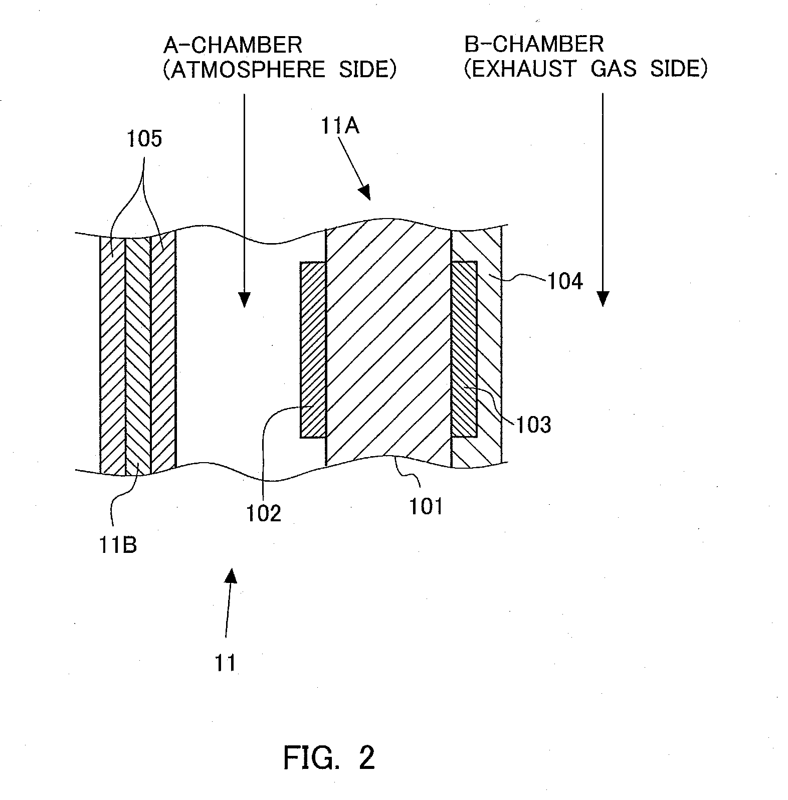
[0047] FIG. 3 is a view showing a relation between a temperature of exhaust gas ET in the surrounding of the air fuel ratio sensor 11 to be predicted, and an offset amount (a target offset amount) of the target temperature of the sensor element 11A from a reference temperature. The temperature of the exhaust gas ET on the axis of abscissa is the temperature of the exhaust gas in the surrounding of the air fuel ratio sensor 11 predicted from the operating state of the internal combustion engine 1, and is calculated based on the accelerator opening degree used in the torque demand control. The reference temperature shown in FIG. 3 is the reference temperature of the sensor element 11A, and is 700 degrees C., for example. This reference temperature is a temperature which becomes a reference at the time of controlling the temperature of the sensor element 11A so as to fall within the predetermined range. Here, note that the reference temperature may also be set to a temperature at which the detection accuracy of the air fuel ratio sensor 11 becomes the highest. Accordingly, the temperature of the exhaust gas ET indicated by ET3 shows that the predicted temperature of the exhaust gas in the surrounding of the air fuel ratio sensor 11 is equal to the reference temperature of the sensor element 11A.
[0048] The target offset amount on the axis of ordinate in FIG. 3 indicates an offset amount from the reference temperature at the time of setting the target temperature of the sensor element 11A. "+30" in the target offset amount represents that the target temperature of the sensor element 11A is made higher by 30 degrees C. than the reference temperature, and "0" represents that the target temperature of the sensor element 11A is made equal to the reference temperature, and "-30" represents that the target temperature of the sensor element 11A is made lower by 30 degrees C. than the reference temperature.
[0049] In cases where the temperature of the exhaust gas ET is lower than ET3, the predicted temperature of the exhaust gas ET in the surrounding of the air fuel ratio sensor 11 will be lower than the reference temperature. In this case, when the exhaust gas of low temperature actually reaches the air fuel ratio sensor 11, the heating of the air fuel ratio sensor 11 by the heater 11B will be late or insufficient, so the temperature of the sensor element 11A may drop. For that reason, in cases where the temperature of the exhaust gas in the surrounding of the air fuel ratio sensor 11 is predicted to become lower than the reference temperature (i.e., in cases where the temperature of the exhaust gas ET is predicted to become lower than ET3), the temperature of the sensor element 11A is raised in advance. In this case, the sensor element impedance control is carried out in a state where the target temperature of the sensor element 11A in the sensor element impedance control is made higher than the reference temperature.
[0050] In FIG. 3, in cases where the temperature of the exhaust gas ET is in a range from ET1 to ET2, the smaller the temperature of the exhaust gas ET, the larger the target offset amount is made. That is, by making the target offset amount larger as the predicted temperature of the exhaust gas ET becomes lower, the temperature of the sensor element 11A is made high in advance according to the predicted temperature of the exhaust gas ET. Here, note that in FIG. 3, the target offset amount is continuously changed according to the temperature of the exhaust gas ET, but instead of this, the target offset amount may be changed in a stepwise manner.
[0051] On the other hand, an upper limit of the target offset amount is set to +30 degrees C. For this reason, in cases where the temperature of the exhaust gas ET is lower than ET1, the target offset amount is fixed to +30 degrees C. Here, note that in cases where the prediction of the temperature of the exhaust gas is wrong, the temperature of the sensor element 11A may deviate from the predetermined range, so a certain amount of margin is given to the upper limit of the target offset amount. That is, the upper limit of the target offset amount is set so as to change the target temperature of the sensor element 11A in a range which is narrower than the predetermined range (e.g., a range from 650 degrees C. to 750 degrees C.). However, the upper limit of the target offset amount may be increased to an offset amount (e.g., +50 degrees C.) corresponding to the upper limit (e.g., 750 degrees C.) of the predetermined range. By doing in this manner, the target temperature of the sensor element 11A can be adjusted within the predetermined range, so that when the heater 11B heats the sensor element 11A, it is possible to suppress the temperature of the sensor element 11A from becoming excessively high, and hence deviating from the predetermined range. ET1 is an upper limit value of the temperature of the exhaust gas at which the temperature of the sensor element 11A may exceed the upper limit of the predetermined range, when the target offset amount is made larger according to the temperature of the exhaust gas.
[0052] Moreover, when the temperature of the exhaust gas ET is in a range from ET2 to ET3 even if it is lower than ET3, the target offset amount is set to 0. Here, the predicted temperature of the exhaust gas ET is close to the reference temperature, and hence, even in cases where the predicted temperature of the exhaust gas ET is lower than the reference temperature, the amount of heat taken from the sensor element 11A is small, as a result of which in this temperature range, the temperature of the sensor element 11A becomes a value close to the reference temperature, even if the target temperature is not made to change. Accordingly, in the range from ET2 to ET3, the target offset amount may be set to 0, without being changed. With this, simplification of control can be attained. However, even if the temperature of the exhaust gas ET is in the range from ET2 to ET3, the lower the temperature of the exhaust gas ET, the larger the target offset amount may be made, as in the case where the temperature of the exhaust gas ET is in the range from ET1 to ET2. ET2 can be obtained as a lower limit of the temperature of the exhaust gas ET at which the temperature of the sensor element 11A can be made to fall within the predetermined range, even if the target temperature or the target offset amount is not changed.
[0053] In cases where the temperature of the exhaust gas ET is higher than ET3, the predicted temperature of the exhaust gas ET in the surrounding of the air fuel ratio sensor 11 will be higher than the reference temperature. In this case, when the exhaust gas of high temperature actually reaches the air fuel ratio sensor 11, the temperature of the sensor element 11A may rise, even if the amount of heating by the heater 11B is decreased, which will be late. For that reason, in cases where the temperature of the exhaust gas in the surrounding of the air fuel ratio sensor 11 is predicted to become higher than the reference temperature (i.e., in cases where the temperature of the exhaust gas ET is predicted to become higher than ET3), the temperature of the sensor element 11A is lowered in advance. In this case, the sensor element impedance control is carried out in a state where the target temperature of the sensor element 11A in the sensor element impedance control is made lower than the reference temperature.
[0054] In FIG. 3, in cases where the temperature of the exhaust gas ET is in a range from ET4 to ET5, the larger the temperature of the exhaust gas ET, the smaller the target offset amount is made. That is, by making the target offset amount smaller as the predicted temperature of the exhaust gas ET becomes higher, the temperature of the sensor element 11A is made low in advance according to the predicted temperature of the exhaust gas ET. Here, note that in FIG. 3, the target offset amount is continuously changed according to the temperature of the exhaust gas ET, but instead of this, the target offset amount may be changed in a stepwise manner.
[0055] On the other hand, a lower limit of the target offset amount is set to -30 degrees C. For this reason, in cases where the temperature of the exhaust gas ET is higher than ET5, the target offset amount is fixed to -30 degrees C. Here, note that in cases where the prediction of the temperature of the exhaust gas is wrong, the temperature of the sensor element 11A may deviate from the predetermined range, so a certain amount of margin is given to the lower limit of the target offset amount. That is, the lower limit of the target offset amount is set so as to change the target temperature of the sensor element 11A in a range which is narrower than the predetermined range. However, the lower limit of the target offset amount may be decreased to an offset amount (e.g., -50 degrees C.) corresponding to the lower limit (e.g., 650 degrees C.) of the predetermined range. ET5 is a temperature at which the temperature of the sensor element 11A may be lower than the lower limit of the predetermined range. By doing in this manner, the target temperature of the sensor element 11A can be adjusted within the predetermined range, thus making it possible to suppress the temperature of the sensor element 11A from becoming excessively low, and hence deviating from the predetermined range. ET5 is a lower limit value of the temperature of the exhaust gas at which the temperature of the sensor element 11A may fall below the lower limit of the predetermined range, when the target offset amount is made smaller according to the temperature of the exhaust gas.
[0056] Further, when the temperature of the exhaust gas ET is in a range from ET3 to ET4 even if it is higher than ET3, the target offset amount is set to 0. Here, the predicted temperature of the exhaust gas ET is close to the reference temperature, and hence, even in cases where the predicted temperature of the exhaust gas ET is higher than the reference temperature, the amount of heat given to the sensor element 11A is small, as a result of which in this temperature range, the temperature of the sensor element 11A becomes a value close to the reference temperature, even if the target temperature is not made to change. Accordingly, in the range from ET3 to ET4, the target offset amount may be set to 0, without being changed. With this, simplification of control can be attained. However, even if the temperature of the exhaust gas ET is in the range from ET3 to ET4, the lower the temperature of the exhaust gas ET, the smaller the target offset amount may be made, as in the case where the temperature of the exhaust gas ET is in the range from ET4 to ET5. ET4 can be obtained as an upper limit of the temperature of the exhaust gas ET at which the temperature of the sensor element 11A can be made to fall within the predetermined range, even if the target temperature or the target offset amount is not changed. Each of ET1, ET2, ET3, ET4 and ET5 can be obtained in advance by experiments, simulations, or the like.
[0057] Here, note that the amount of heat taken by the exhaust gas from the sensor element 11A per unit time changes with the flow rate of the exhaust gas, too. Accordingly, the target offset amount may be set in consideration of the flow rate of the exhaust gas, in addition to the temperature of the exhaust gas ET. For example, in cases where the temperature of the exhaust gas ET is lower than ET3 in FIG. 3, the larger the flow rate of the exhaust gas, the larger the rate of temperature drop of the sensor element 11A becomes, even if the temperature of the exhaust gas ET is the same. On the other hand, in cases where the temperature of the exhaust gas ET is higher than ET3 in FIG. 3, the larger the flow rate of the exhaust gas, the larger the rate of temperature rise of the sensor element 11A becomes, even if the temperature of the exhaust gas ET is the same. Thus, a difference in the rate of temperature change of the sensor element 11A occurs according to the flow rate of the exhaust gas, the temperature of the sensor element 11A may not immediately change due to a change in the temperature of the exhaust gas ET, but it may take a certain period of time. Accordingly, when the target offset amount of the sensor element 11A is made to change according to the temperature of the exhaust gas ET, the target offset amount will change excessively with respect to the amount of increase or decrease of the heat in the sensor element 11A, thus giving rise to a fear that the temperature of the sensor element 11A may deviate from the predetermined range.
[0058] For that reason, the target offset amount may be corrected according to the flow rate of the exhaust gas. The prediction of the flow rate of the exhaust gas flowing through the surrounding of the air fuel ratio sensor 11 has a correlation with the accelerator opening degree used in the torque demand control, or the engine rotational speed and the engine load factor calculated in the torque demand control, and so is performed based on these values. Here, note that there is a correlation among the engine rotational speed, the engine load factor, and the flow rate of the exhaust gas at the time when the exhaust gas having flowed out from the internal combustion engine 1 reaches the air fuel ratio sensor 11 in the case where the internal combustion engine 1 is operated at the engine rotational speed and the engine load factor, and hence, this relation has been obtained and mapped in advance by experiments, simulations or the like, and stored in the ECU 10.
[0059] FIG. 4 is a view for correcting the target offset amount shown in FIG. 3. In FIG. 4, the axis of ordinate represents the predicted temperature of exhaust gas ET, and the axis of abscissa represents the predicted flow rate of exhaust gas EQ. The flow rate of exhaust gas EQ is the flow rate of the exhaust gas in the surrounding of the air fuel ratio sensor 11 predicted from the operating state of the internal combustion engine 1, and is calculated based on the accelerator opening degree used in the torque demand control. In FIG. 4, "NO CORRECTION" indicates that the target offset amount shown in FIG. 3 is not corrected; "SMALL" indicates that the target offset amount shown in FIG. 3 is corrected to become small (i.e., a negative value becomes large); and "LARGE" indicates that the target offset amount shown in FIG. 3 is corrected to become large (i.e., a positive value becomes large).
[0060] As shown in FIG. 4, in cases where the predicted flow rate of exhaust gas EQ is smaller than a predetermined flow rate, the correction of the target offset amount based on the flow rate of exhaust gas EQ is not carried out, irrespective of the predicted temperature of exhaust gas ET. The predetermined flow rate referred to herein is an upper limit value of the flow rate of exhaust gas at which the temperature of the sensor element 11A is able to be controlled to within the predetermined range, by carrying out the sensor element impedance control based on the target offset amount shown in FIG. 3. That is, in cases where the flow rate of exhaust gas EQ is smaller than the predetermined flow rate, the influence of the flow rate of exhaust gas EQ on the temperature rise or temperature drop of the sensor element 11A is small, so the correction of the target offset amount according to the flow rate of exhaust gas EQ is not carried out. Accordingly, the target temperature of the sensor element 11A is set according to the relation shown in FIG. 3.
[0061] On the other hand, even in cases where the predicted flow rate of exhaust gas EQ is more than the predetermined flow rate, if the temperature of the exhaust gas ET is in the vicinity of the reference temperature, the influence of the flow rate of exhaust gas EQ on the temperature rise or temperature drop of the sensor element 11A is small. For that reason, the temperature of the sensor element 11A is suppressed from deviating from the predetermined range, so the correction of the target offset amount according to the flow rate of exhaust gas EQ is not carried out. Accordingly, the target temperature of the sensor element 11A is set according to the relation shown in FIG. 3. The lower limit and the upper limit of the temperature of the exhaust gas ET at this time may be set to ET2 and ET4 in FIG. 3, respectively, or may also be values different from these. These values can be obtained in advance through experiments, simulations or the like.
[0062] In addition, in a range indicated by "SMALL" in FIG. 4, even if the temperature of the exhaust gas ET is the same, the target offset amount is corrected so as to be smaller (i.e., the amount of deviation of the target temperature from the reference temperature becomes larger) when the predicted flow rate of the exhaust gas is large than when it is small. In cases where the predicted flow rate of exhaust gas EQ is more than the predetermined flow rate, and in cases where the predicted temperature of exhaust gas ET is higher than an upper limit of a range indicated by "NO CORRECTION" in FIG. 4, the rate of temperature rise of the sensor element 11A due to the heat received from the exhaust gas becomes larger according to the flow rate of the exhaust gas. For that reason, the target offset amount obtained based on FIG. 3 is corrected according to the flow rate of the exhaust gas. However, the lower limit of the target offset amount thus corrected is set to the lower limit shown in FIG. 3 (e.g., -30 degrees C.). With this, the temperature of the sensor element 11A is suppressed from deviating from the predetermined range, in cases where the prediction of the temperature or the flow rate of the exhaust gas is wrong. In this range, the temperature of the exhaust gas ET is high and the flow rate of exhaust gas EQ is large, so the temperature of the sensor element 11A is predicted to further rise. For this reason, the temperature of the sensor element 11A is made further lower in advance, whereby the temperature of the sensor element 11A is suppressed from exceeding the upper limit of the predetermined range.
[0063] On the other hand, in a range indicated by "LARGE" in FIG. 4, even if the temperature of the exhaust gas ET is the same, the target offset amount is corrected so as to be larger (i.e., the amount of deviation of the target temperature from the reference temperature becomes larger) when the predicted flow rate of the exhaust gas is large than when it is small. In cases where the predicted flow rate of exhaust gas EQ is more than the predetermined flow rate, and in cases where the predicted temperature of exhaust gas ET is lower than a lower limit of the range indicated by "NO CORRECTION" in FIG. 4, the rate of temperature drop of the sensor element 11A due to the heat deprived from the exhaust gas becomes larger according to the flow rate of the exhaust gas. For that reason, the target offset amount obtained based on FIG. 3 is corrected according to the flow rate of the exhaust gas. However, the upper limit of the target offset amount thus corrected is set to the upper limit shown in FIG. 3 (e.g., +30 degrees C.). With this, the temperature of the sensor element 11A is suppressed from deviating from the predetermined range, in cases where the prediction of the temperature or the flow rate of the exhaust gas is wrong. In this range, the temperature of the exhaust gas ET is low and the flow rate of exhaust gas EQ is large, so the temperature of the sensor element 11A is predicted to further drop. For this reason, the temperature of the sensor element 11A is made further higher in advance, whereby the temperature of the sensor element 11A is suppressed from falling below the lower limit of the predetermined range.
[0064] Here, note that the range of "NO CORRECTION" is provided in FIG. 4, but instead of this, without providing the range of "NO CORRECTION", the target offset amount may be corrected so as to make the amount of deviation of the target temperature from the reference temperature larger when the flow rate of exhaust gas EQ is large than when it is small, as long as the temperature of the exhaust gas ET is the same.
[0065] Also, note that a new target offset amount may be obtained by multiplying a correction coefficient obtained by the relation shown in FIG. 4 to the target offset amount shown in FIG. 3, or a relation among the temperature of the exhaust gas ET, the flow rate of exhaust gas EQ and the target offset amount may have been obtained and mapped in advance by experiments, simulations or the like, and stored in the ECU 10.
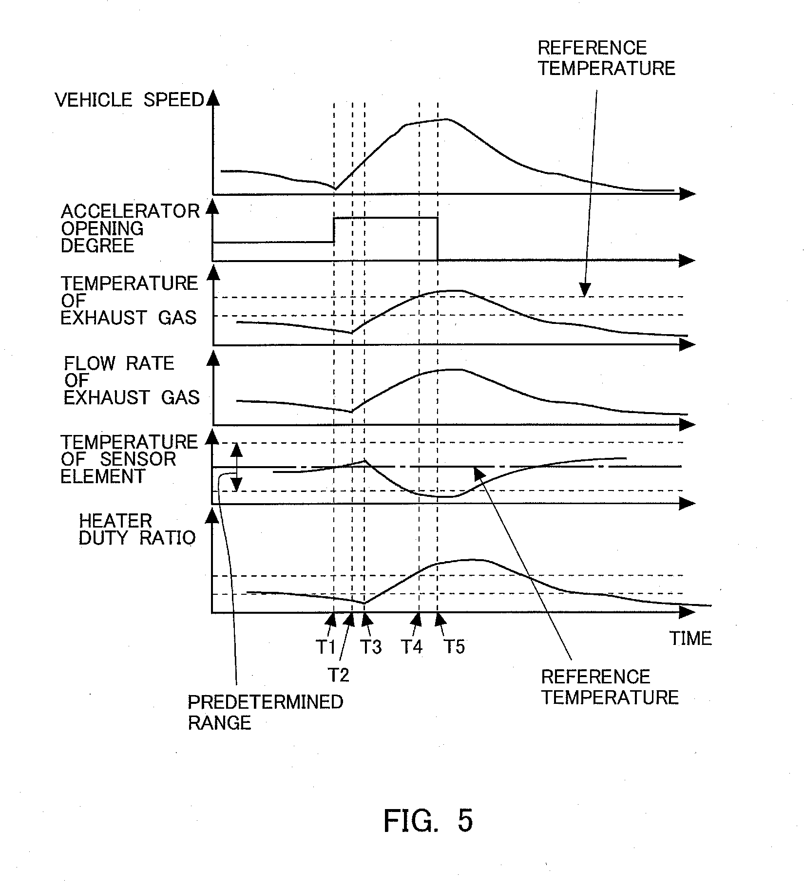
[0066] FIG. 5 is a time chart showing the changes over time of a variety of kinds of values in the case of setting the target temperature of the sensor element 11A constant at the reference temperature. In FIG. 5, there are shown, in order from the top, the vehicle speed, the accelerator opening degree, the temperature of the exhaust gas, the flow rate of the exhaust gas, the temperature of the sensor element 11A, and the duty ratio of the heater 11B (heater duty). The temperature of the exhaust gas and the flow rate of the exhaust gas are values in the surrounding or periphery of the air fuel ratio sensor 11, and it is assumed that they are equal to the predicted temperature of the exhaust gas and the predicted flow rate of the exhaust gas as mentioned above. An alternate long and short dash line in the temperature of the sensor element 11A shows the target temperature thereof in the sensor element impedance control, and a solid line shows the actual temperature thereof. Here, note that in FIG. 5, the target temperature of the sensor element 11A is constant at the reference temperature. FIG. 5 may also be a time chart in the case of carrying out conventional sensor element impedance control.
[0067] In FIG. 5, when the accelerator opening degree becomes large at T1, the vehicle speed goes up. It takes a certain period of time (i.e., a period of time from T1 to T2) before the gas discharged from the internal combustion engine 1 at T1 reaches the air fuel ratio sensor 11. At T2 after this response delay, the temperature of the exhaust gas and the flow rate of the exhaust gas in the surrounding or vicinity of the air fuel ratio sensor 11 begin to increase. In FIG. 5, because the temperature of the exhaust gas in T2 is lower than the reference temperature, the amount of heat taken from the sensor element 11A increases with an increase in the flow rate of the exhaust gas. Accordingly, the temperature of the sensor element 11A begins to decrease at T3, later than the increase in the flow rate of the exhaust gas.
[0068] In order to increase the temperature of the sensor element 11A from T3, the heater duty increases, but the temperature rise of the sensor element 11A is late so the temperature of the sensor element 11A drops. This temperature drop of the sensor element 11A continues until the temperature of the exhaust gas reaches the reference temperature at T4. For this reason, the temperature of the sensor element 11A will become lower than the lower limit of the predetermined range in a period of time from T3 to T4. When the temperature of the exhaust gas exceeds the reference temperature at T4, the sensor element 11A is heated by the exhaust gas, so the temperature drop of the sensor element 11A ends. For this reason, the heater duty does not substantially increase. After that, the sensor element 11A is heated by the heater 11B and the exhaust gas, so the temperature of the sensor element 11A goes up.
[0069] At T5, the accelerator opening degree becomes 0, and the vehicle speed begins to decrease. Thus, when the accelerator opening degree becomes 0 and the vehicle speed decreases, the flow rate of the exhaust gas accordingly becomes smaller, so the sensor element 11A can be heated by the heater 11B, even if the temperature of the exhaust gas is equal to or less than the reference temperature. As a result, the temperature of the sensor element 11A continues to rise. Thereafter, the temperature of the sensor element 11A reaches the reference temperature.
[0070] In this manner, when the target temperature of the sensor element 11A is fixed at the reference temperature, the temperature of the sensor element 11A may become lower than the lower limit of the predetermined range, in cases where the temperature of the exhaust gas is low.
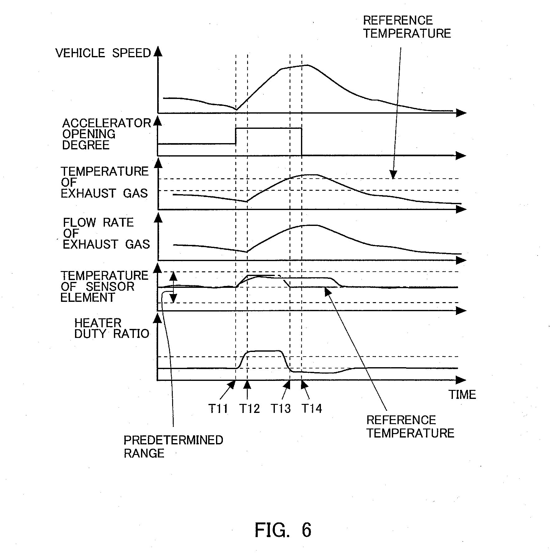
[0071] On the other hand, FIG. 6 is a time chart showing the changes over time of a variety of kinds of values in cases where sensor element impedance control according to this embodiment is carried out. In FIG. 6, similar to FIG. 5, there are shown, in order from the top, the vehicle speed, the accelerator opening degree, the temperature of the exhaust gas, the flow rate of the exhaust gas, the temperature of the sensor element 11A, and the duty ratio of the heater 11B. Here, note that the changes over time of the vehicle speed, the accelerator opening degree, the temperature of the exhaust gas and the flow rate of the exhaust gas in FIG. 6 are the same as in FIG. 5. Also, note that the sensor element impedance control according to this embodiment is started from T11.
[0072] When the accelerator opening degree becomes large at T11, the ECU 10 predicts the temperature of the exhaust gas and the flow rate of the exhaust gas, whereby the target temperature of the sensor element 11A is changed. At T12, the temperature of the exhaust gas and the flow rate of the exhaust gas in the surrounding of the air fuel ratio sensor 11 change corresponding to an increase in the accelerator opening degree at T11, but the rise of the target temperature of the sensor element 11A begins before T12. That is, because it is predicted that the predicted temperature of the exhaust gas is lower than the reference temperature and that the flow rate of the exhaust gas increases, the target temperature of the sensor element 11A is raised in advance from T11 so that the temperature of the sensor element 11A does not drop. For that reason, the heater duty increases from T11. After that, too, the temperature of the exhaust gas and the flow rate of the exhaust gas are successively predicted, and the target temperature of the sensor element 11A is adjusted accordingly.
[0073] The exhaust gas at the temperature and the flow rate predicted at T11 reaches the surrounding of the air fuel ratio sensor 11 at T12. At this time, the actual temperature of the sensor element 11A is higher than the reference temperature, and hence, even if the flow rate of the exhaust gas at low temperature increases, the temperature of the sensor element 11A is suppressed from becoming lower than the lower limit of the predetermined range.
[0074] Moreover, at T13, the temperature of the exhaust gas has reached the reference temperature. Accordingly, after T13, the sensor element 11A is heated by the exhaust gas, so the target temperature is dropped so as to make the temperature of the sensor element 11A lower. For that reason, the heater duty is also made small. Then, at T14, the vehicle speed begins to decrease.
[0075] In this manner, when the target temperature of the sensor element 11A is changed according to the predicted temperature of the exhaust gas and the predicted flow rate of the exhaust gas, it is possible to suppress the temperature of the sensor element 11A from becoming lower than the lower limit of the predetermined range, even in cases where the temperature of the exhaust gas is low and the flow rate of the exhaust gas is large.
[0076] FIG. 7 is a flow chart showing a flow or routine for setting the duty ratio in the sensor element impedance control according to this embodiment. The routine in this flow chart is carried out by means of the ECU 10 at each predetermined time interval. Here, note that the sensor element impedance control is separately carried out by the ECU 10.
[0077] In step S101, the temperature of the exhaust gas is predicted, and in step S102, the flow rate of the exhaust gas is predicted. The temperature of the exhaust gas and the flow rate of the exhaust gas referred to herein are those in the surrounding of the air fuel ratio sensor 11. The future temperature of the exhaust gas and the future flow rate of the exhaust gas are calculated based on the engine rotational speed and the engine load factor which are calculated in the torque demand control. A map is used for this calculation. This map takes into consideration a drop or decrease in the temperature of the exhaust gas by the release of heat at the time when the exhaust gas flows through the exhaust passage 2.
[0078] In step S103, the target temperature of the sensor element 11A is calculated based on the temperature of the exhaust gas calculated in step S101 and the flow rate of the exhaust gas calculated in step S102. A map is used for the calculation of this target temperature.
[0079] In step S104, the duty ratio in the sensor element impedance control is calculated. The relation between the target temperature and the duty ratio has been obtained in advance by experiments, simulations, or the like. Then, in step S105, the duty ratio calculated in step S104 is set as the duty ratio in the sensor element impedance control. Here, note that in this embodiment, the ECU 10 carries out the processing of steps S101 through S105, and thus functions as a controller in the present disclosure.
[0080] Here, note that when the temperature of the sensor element 11A changes suddenly, the sensor element 11A may be damaged, or the characteristic of the sensor element 11A may be changed to shift the detected value thereof. Accordingly, when the target temperature of the sensor element 11A is changed, the breakage or damage of the sensor element 11A and the deviation of the detected value thereof may be suppressed by providing an upper limit on the rate of change of the target temperature, etc., so as to change the target temperature in a gradual manner. The upper limit of the rate of change of the target temperature has been obtained in advance by experiments, simulations or the like as a rate of change at which the breakage or damage of the sensor element 11A can be suppressed, or as a rate of change at which the deviation of the detected value of the air fuel ratio sensor 11 falls within an allowable range.
[0081] In this embodiment, the temperature of the exhaust gas and the flow rate of the exhaust gas are predicted and the target temperature of the sensor element 11A is set based on these predicted values, but instead of this, only the temperature of the exhaust gas may be predicted, and the target temperature of the sensor element 11A may be set based on this predicted value. That is, although the target offset amount is set based on the relation shown in FIG. 3, the correction based on the relation shown in FIG. 4 may not be made. Here, in cases where the predicted temperature of the exhaust gas is higher than the reference temperature, the larger the flow rate of the exhaust gas, the more easily the temperature of the sensor element 11A rises. On the other hand, in cases where the predicted temperature of the exhaust gas is lower than the reference temperature, the larger the flow rate of the exhaust gas, the more easily the temperature of the sensor element 11A drops. Accordingly, by setting the target temperature of the sensor element 11A in consideration of the flow rate of the exhaust gas, it becomes possible to perform the temperature control of the sensor element 11A with higher precision. However, even in cases where the flow rate of the exhaust gas is not taken into consideration, it is possible to set the target temperature of the sensor element 11A according to the change of the temperature of the exhaust gas, and hence, the target temperature can also be set without taking into consideration the flow rate of the exhaust gas.
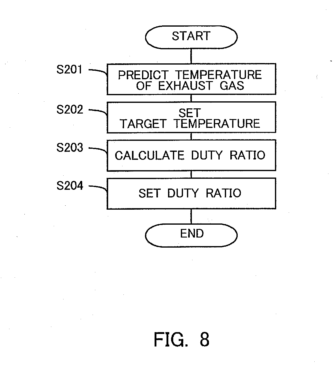
[0082] FIG. 8 is a flow chart showing a flow or routine for setting the duty ratio in the sensor element impedance control according to this embodiment, in cases where the flow rate of exhaust gas is not taken into consideration. The routine in this flow chart is carried out by means of the ECU 10 at each predetermined time interval. Here, note that the sensor element impedance control is separately carried out by the ECU 10.
[0083] In step S201, the temperature of the exhaust gas is predicted. The temperature of the exhaust gas referred to herein represents the temperature of the exhaust gas in the surrounding of the air fuel ratio sensor 11. The future temperature of the exhaust gas is calculated based on the engine rotational speed and the engine load factor which are calculated in the torque demand control. A map is used for this calculation. This map takes into consideration the drop or decrease in the temperature of the exhaust gas by the release of heat at the time when the exhaust gas flows through the exhaust passage 2.
[0084] In step S202, the target temperature of the sensor element 11A is calculated based on the temperature of the exhaust gas calculated in step S201. A map is used for the calculation of this target temperature.
[0085] In step S203, the duty ratio in the sensor element impedance control is calculated. The relation between the target temperature and the duty ratio has been obtained in advance by experiments, simulations, or the like. Then, in step S204, the duty ratio calculated in step S203 is set as the duty ratio in the sensor element impedance control. Here, note that in this embodiment, the ECU 10 carries out the processing of steps S201 through S204, and thus functions as the controller in the present disclosure.
[0086] As described above, according to this embodiment, the target temperature in the sensor element impedance control is set based on the predicted temperature of exhaust gas and the predicted flow rate of exhaust gas, and the temperature of the sensor element 11A has been changed before the temperature of the exhaust gas and the flow rate of exhaust gas actually change, so it is possible to suppress the adjustment of the temperature of the sensor element 11A from becoming late. With this, the temperature of the sensor element 11A can be maintained within the predetermined range, thus making it possible to suppress a decrease in the detection accuracy of the air fuel ratio sensor 11.
[0087] Here, it is also considered that even in cases where the temperature of the sensor element 11A is made to change in advance based on the predicted temperature of exhaust gas and the predicted flow rate of exhaust gas, the exhaust gas of the predicted temperature reaches the air fuel ratio sensor 11 before the change of the temperature of the sensor element 11A is completed. That is, the adjustment of the temperature of the sensor element 11A may be late. However, even in such a case, the adjustment of the temperature of the sensor element 11A is started before the exhaust gas actually reaches the sensor element 11A. Accordingly, the adjustment of the temperature of the sensor element 11A can be started more early than when the adjustment of the temperature of the sensor element 11A is started after the temperature of the sensor element 11A has changed, so a certain amount of effect can be expected.
[0088] In addition, in this embodiment, an explanation has been made using the air fuel ratio sensor 11 as an example, the present disclosure can be applied to other sensors each having a heater. For example, even in cases where a heater is controlled in a PM sensor, an NOx sensor, or an HC sensor, too, the present disclosure can be applied as in this embodiment. Moreover, in this embodiment, the temperature of the exhaust gas is predicted based on the engine rotational speed and the engine load factor which are obtained in the torque demand control, but instead of this, the temperature sensor 12 may directly detect the temperature of the gas discharged from the internal combustion engine 1. In this case, it is preferable to arrange the temperature sensor 12 as close to the internal combustion engine 1 as possible. Then, the temperature of the exhaust gas in the surrounding of the air fuel ratio sensor 11 can be predicted by further estimating a temperature drop until the exhaust gas with its temperature detected by this temperature sensor 12 flows through the exhaust passage 2 and reaches the air fuel ratio sensor 11. Further, the temperature of the gas discharged from the internal combustion engine 1 can be estimated based not only on the engine rotational speed and the engine load factor obtained in the torque demand control, but also on the engine rotational speed detected by the crank position sensor 21 and the engine load factor detected by the accelerator opening sensor 22, and hence, the temperature of the exhaust gas in the surrounding of the air fuel ratio sensor 11 may be predicted based on the temperature of this gas. The relation of the temperature of the gas discharged from the internal combustion engine 1 or the temperature of the exhaust gas in the surrounding of the air fuel ratio sensor 11 with respect to the number of engine revolutions per unit time and the engine load can be obtained in advance by experiments, simulations, or the like.
[0089] Furthermore, the degree of opening of the throttle valve 8 and the temperature of the gas discharged from the internal combustion engine 1 are in correlation with each other, so the temperature of the gas discharged from the internal combustion engine 1 may be predicted based on the degree of opening of the throttle valve 8. The temperature of the exhaust gas in the surrounding of the air fuel ratio sensor 11 can be predicted by further estimating the temperature drop until this exhaust gas flows through the exhaust passage 2 and reaches the air fuel ratio sensor 11.
Second Embodiment
[0090] In the first embodiment, the temperature of the exhaust gas and the flow rate of the exhaust gas are predicted based on the accelerator opening degree, etc., and the target temperature of the sensor element 11A is set based on the temperature of the exhaust gas and the flow rate of the exhaust gas thus predicted. On the other hand, in a second embodiment, the target temperature of the sensor element 11A is set directly from the accelerator opening degree. Here, in cases where the accelerator opening degree becomes larger, the required torque of the internal combustion engine 1 becomes larger, so the amount of intake air and the amount of fuel injection are increased, and the temperature of the exhaust gas becomes higher, and the flow rate of the exhaust gas becomes larger. Similarly, in cases where the accelerator opening degree becomes smaller, the required torque of the internal combustion engine 1 becomes smaller, so the temperature of the exhaust gas becomes lower, and the flow rate of the exhaust gas becomes smaller. Thus, there is a correlation among the accelerator opening degree, the temperature of the exhaust gas, and the flow rate of the exhaust gas. Accordingly, in this second embodiment, in cases where the accelerator opening degree becomes larger, the temperature of the sensor element 11A can become higher, so the temperature of the sensor element 11A is made lower in advance. On the other hand, in cases where the accelerator opening degree becomes smaller, the temperature of the sensor element 11A can become lower, so the temperature of the sensor element 11A is made higher in advance.
[0091] FIG. 9 is a flow chart showing a flow or routine for setting a duty ratio in the sensor element impedance control according to this second embodiment. The routine in this flow chart is carried out by means of the ECU 10 at each predetermined time interval. Here, note that the sensor element impedance control is separately carried out by the ECU 10.
[0092] In step S301, the accelerator opening degree is detected. The accelerator opening degree is detected by the accelerator opening sensor 22. In step S302, the target temperature of the sensor element 11A is calculated based on the accelerator opening degree detected in step S301. A map is used for the calculation of this target temperature. This map is set so that the target temperature of the sensor element 11A becomes lower when the accelerator opening degree is large than when it is small. The map showing the relation between the accelerator opening degree and the target temperature of the sensor element 11A has been obtained in advance by experiments, simulations or the like, and stored in the ECU 10. Here, note that this map is made such that in cases where the accelerator opening degree is such that the temperature of the exhaust gas in the surrounding of the air fuel ratio sensor 11 becomes higher than the reference temperature of the sensor element 11A, the target temperature of the sensor element 11A is made lower than the reference temperature, whereas in cases where the accelerator opening degree is such that the temperature of the exhaust gas in the surrounding of the air fuel ratio sensor 11 becomes lower than the reference temperature of the sensor element 11A, the target temperature of the sensor element 11A is made higher than the reference temperature. Further, this map is also made such that the target temperature falls within the predetermined range. Here, note that the ECU 10 may have stored a physical model or a formula in place of the map, and may calculate the target temperature of the sensor element 11A according to the physical model or the formula.
[0093] In step S303, the duty ratio in the sensor element impedance control is calculated. The relation between the target temperature and the duty ratio has been obtained in advance by experiments, simulations, or the like. Then, in step S304, the duty ratio calculated in step S303 is set as the duty ratio in the sensor element impedance control. Here, note that in this second embodiment, the ECU 10 carries out the processing of steps S302 through S304, and thus functions as the controller in the present disclosure.
[0094] In this manner, it becomes possible to control the temperature of the sensor element 11A in a simplified manner based on the accelerator opening degree.
* * * * *
D00000
D00001
D00002
D00003
D00004
D00005
D00006
D00007
D00008
D00009
XML
uspto.report is an independent third-party trademark research tool that is not affiliated, endorsed, or sponsored by the United States Patent and Trademark Office (USPTO) or any other governmental organization. The information provided by uspto.report is based on publicly available data at the time of writing and is intended for informational purposes only.
While we strive to provide accurate and up-to-date information, we do not guarantee the accuracy, completeness, reliability, or suitability of the information displayed on this site. The use of this site is at your own risk. Any reliance you place on such information is therefore strictly at your own risk.
All official trademark data, including owner information, should be verified by visiting the official USPTO website at www.uspto.gov. This site is not intended to replace professional legal advice and should not be used as a substitute for consulting with a legal professional who is knowledgeable about trademark law.