Tower Step Pegs Having Safety Locks
Davis; Roger
U.S. patent application number 16/021826 was filed with the patent office on 2019-05-09 for tower step pegs having safety locks. The applicant listed for this patent is Roger Davis. Invention is credited to Roger Davis.
| Application Number | 20190136539 16/021826 |
| Document ID | / |
| Family ID | 66326864 |
| Filed Date | 2019-05-09 |
| United States Patent Application | 20190136539 |
| Kind Code | A1 |
| Davis; Roger | May 9, 2019 |
TOWER STEP PEGS HAVING SAFETY LOCKS
Abstract
Some implementations can include step pegs having safety locks.
| Inventors: | Davis; Roger; (Lakeland, FL) | ||||||||||
| Applicant: |
|
||||||||||
|---|---|---|---|---|---|---|---|---|---|---|---|
| Family ID: | 66326864 | ||||||||||
| Appl. No.: | 16/021826 | ||||||||||
| Filed: | June 28, 2018 |
Related U.S. Patent Documents
| Application Number | Filing Date | Patent Number | ||
|---|---|---|---|---|
| 62526411 | Jun 29, 2017 | |||
| Current U.S. Class: | 1/1 |
| Current CPC Class: | E06C 1/381 20130101; E04F 11/0223 20130101; F16B 9/054 20180801; E06C 9/04 20130101; F16B 39/24 20130101; E04H 12/00 20130101; F16B 43/025 20130101 |
| International Class: | E04F 11/022 20060101 E04F011/022; F16B 39/24 20060101 F16B039/24; E04H 12/00 20060101 E04H012/00 |
Claims
1. A tower foot peg comprising: a first vertical section; a horizontal section; a second vertical section having a "V" shaped cross section at a distal end of the second vertical section, wherein the second vertical section includes a threaded hole adjacent the distal end of the second vertical section; a lock washer configured to conform to the "V" shaped cross section of the distal end of the second vertical section; and a bolt configured to secure the lock washer to the second vertical section by passing through a hole in the lock washer 110 and threading into the threaded holed of the second vertical section.
2. The tower foot peg of claim 1, wherein an end of the lock washer is constructed to abut a sleeve protruding from a tower, and have an angled top that is compatible with an angle of the sleeve to permit the lock washer to fit snugly against the sleeve protruding from the tower.
3. The tower foot peg of claim 2, wherein the lock washer is of sufficient size to prevent the second vertical section from slipping out of the sleeve on the tower and thus increase the safety of the step peg.
Description
RELATED APPLICATIONS
[0001] This application claims the benefit of U.S. Application No. 62/526,411, filed on Jun. 29, 2017, and entitled "Tower Step Pegs Having Safety Locks," which is incorporated herein by reference in its entirety.
TECHNICAL FIELD
[0002] Some implementations relate generally to step pegs for climbing utility towers, and more particularly, to utility tower step pegs having safety locks.
BACKGROUND
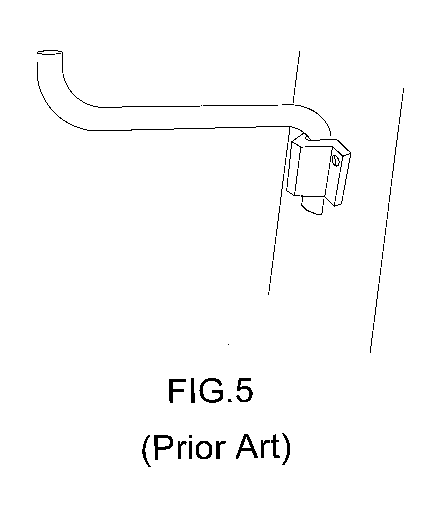
[0003] Conventional tower step pegs (e.g., FIG. 5) are designed to slip into a metal sleeve protruding from a tower (e.g., a utility tower such as a cell tower or power tower). The conventional step pegs are not locked or secured in place, but rather held in place by gravity. Accordingly, the conventional step pegs are susceptible to coming out of the sleeve. Because of the danger of the conventional step pegs coming out, they are sometimes referred to as "suicide pegs."
[0004] Some implementations were conceived in light of the above mentioned needs and limitations, among other things.
BRIEF DESCRIPTION OF THE DRAWINGS
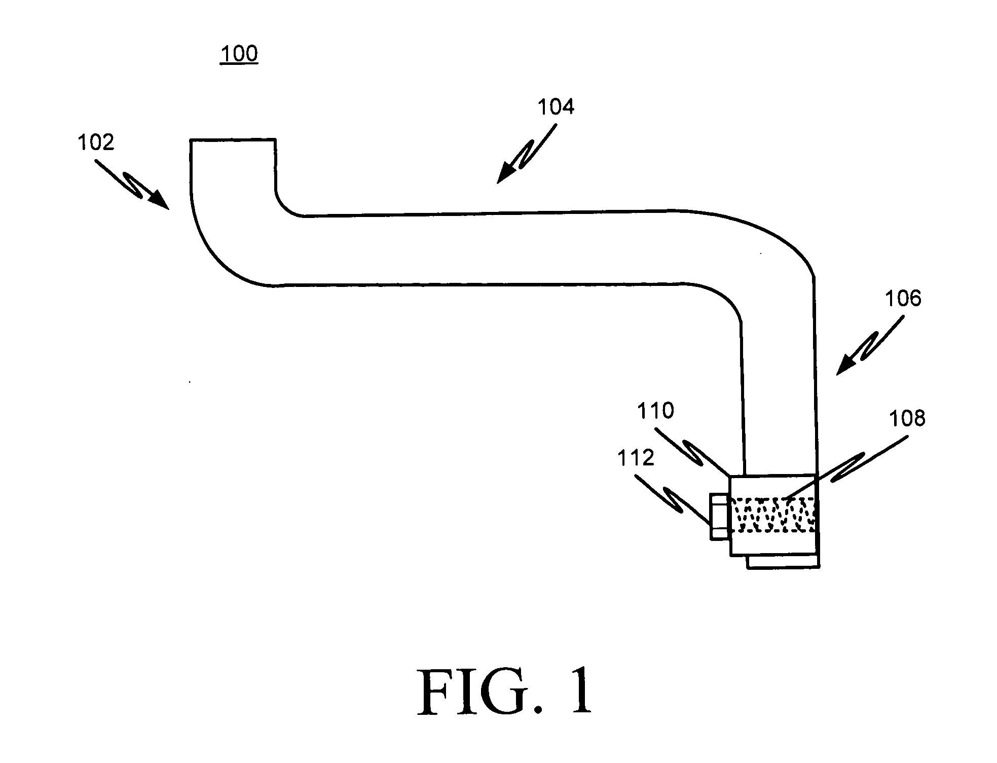
[0005] FIG. 1 is a side view of an example step peg in accordance with some implementations.
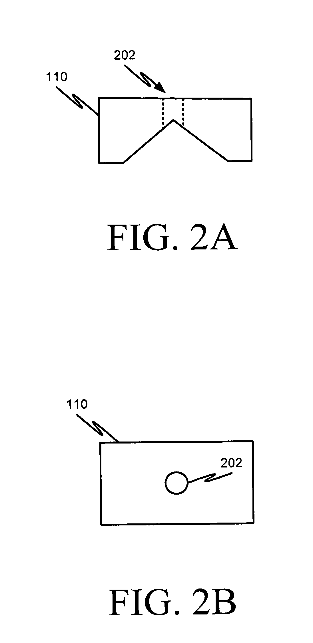
[0006] FIGS. 2A and 2B show a side and top view, respectively, of an example step peg safety lock washer in accordance with some implementations.
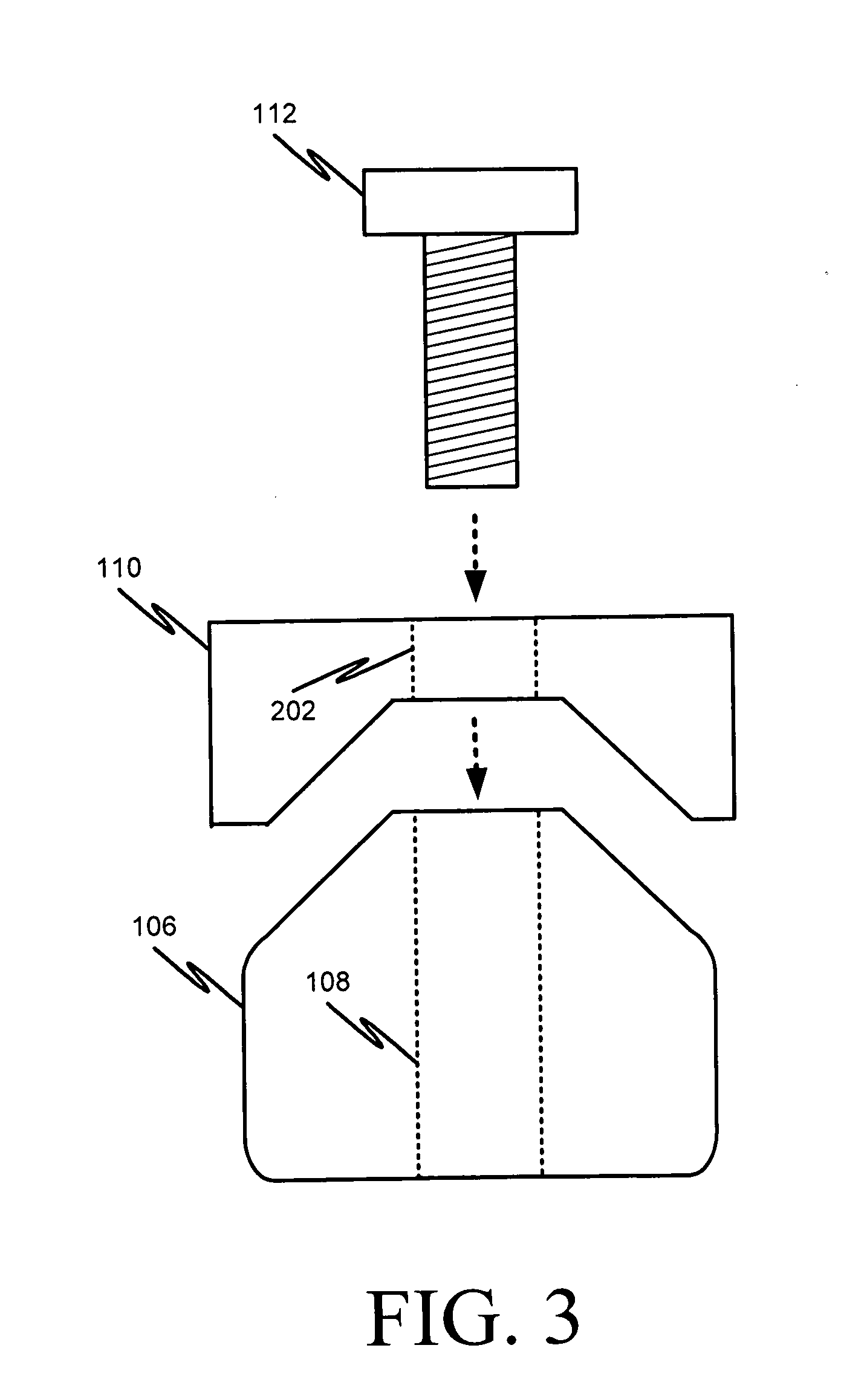
[0007] FIG. 3 is an exploded end view of an example step peg and safety lock in accordance with some implementations.
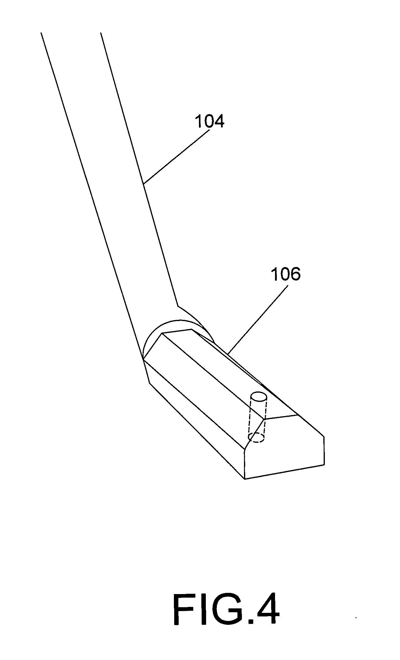
[0008] FIG. 4 is a picture of the triangular shaped end of a step peg in accordance with some implementations.
[0009] FIG. 5 is a picture of a conventional step peg.
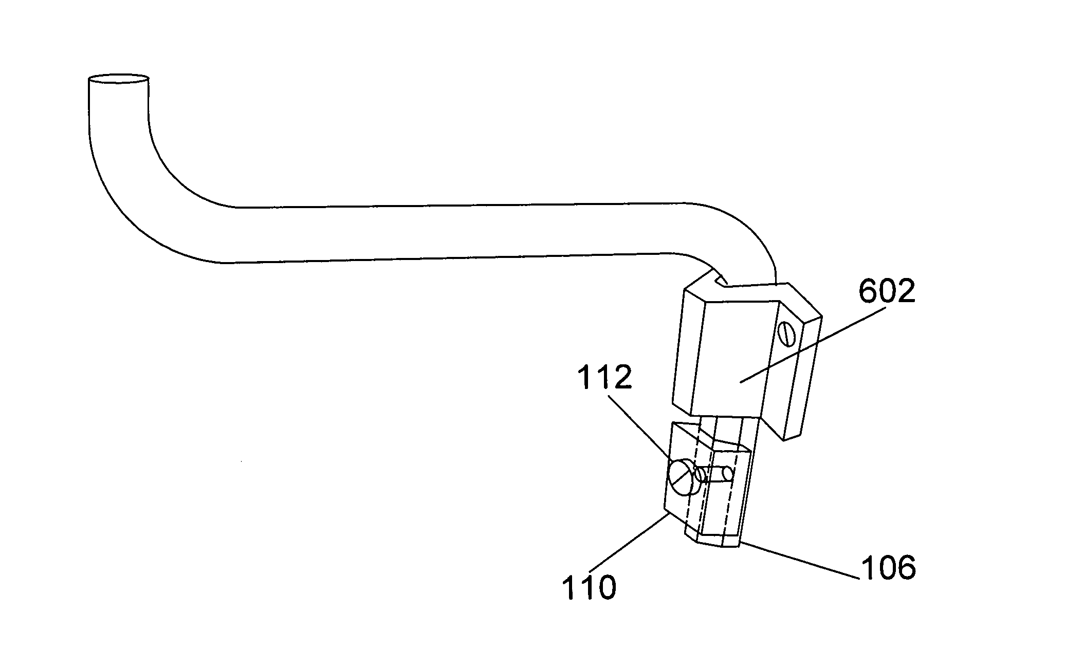
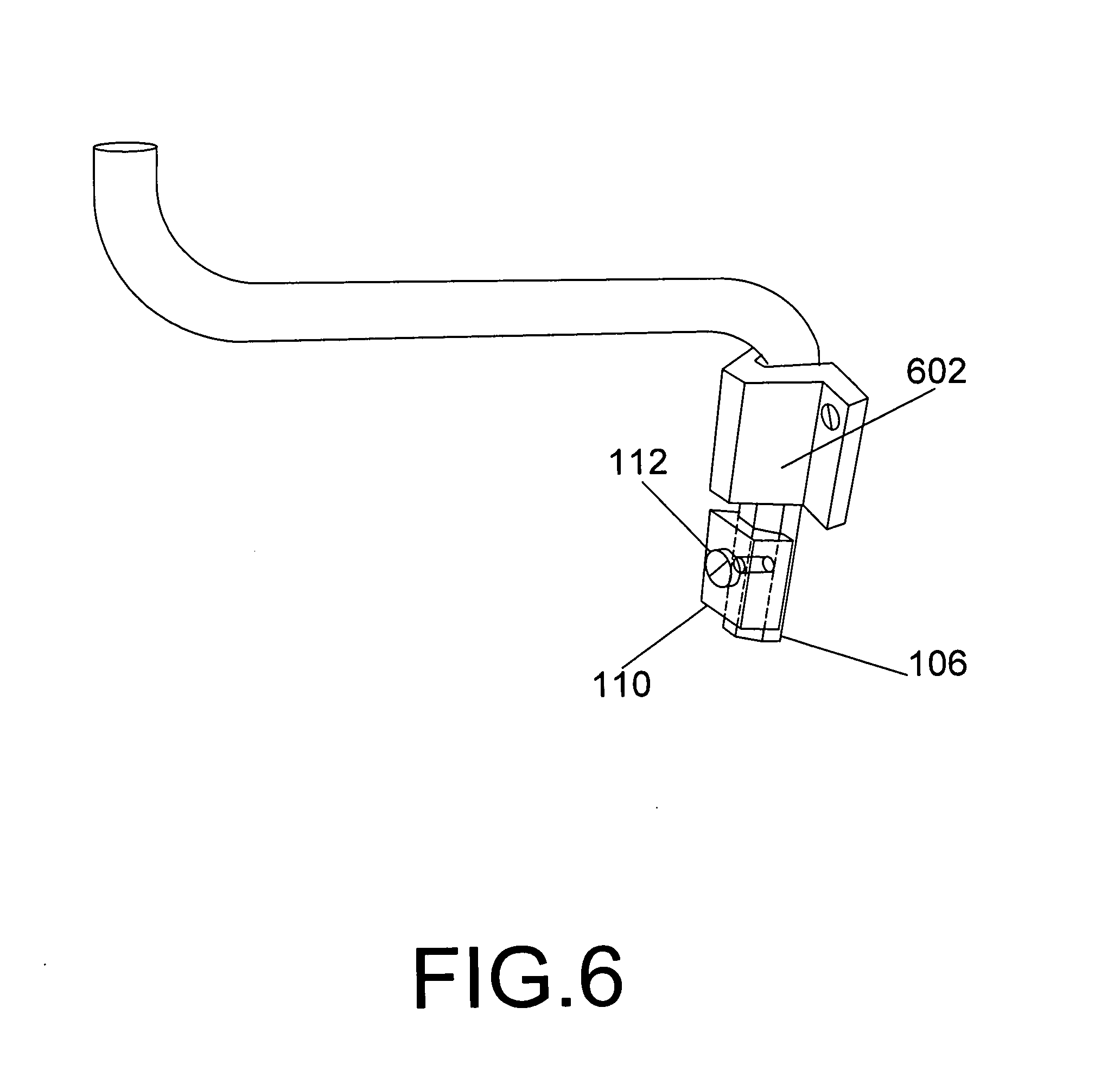
[0010] FIG. 6 is a diagram augmented picture of the step peg of FIG. 5 showing a step peg having the safety lock features in accordance with some implementations.
DETAILED DESCRIPTION
[0011] FIG. 1 is a side view of an example step peg 100 having a first vertical section 102, a horizontal section 104 and a second vertical section 106 having a partially "V" shaped cross section at a distal end. The step peg 100 also includes a threaded hole 108 near the distal end of the second vertical section 106, a lock washer 110 configured to conform to the "V" shaped cross section of the distal end of the second vertical section 106, and a bolt 112 configured to secure the lock washer 110 to the second vertical section 106 by passing through a hole (see, 202 in FIGS. 2A and 2B) in the lock washer 110 and threading into the threaded holed 108 near the distal end of the second vertical section 106.
[0012] The first vertical section 102 can be about 2 inches high. The horizontal section 104 can be about 8 inches long, and the second vertical section can be about 51/4 inches high, which can include about 31/4 inches of partially triangular cross section at the distal end. The step peg 100 can be formed from 3/4 inch round steel stock. The bolt 112 can include a 3/8 inch bolt, and the threaded aperture 202 can be threaded so as to be mechanically compatible with the threads on the bolt 112. The lock washer 110 can be about 1 inch wide by 11/4 inches long by 3/4 inch high and can be formed from galvanized steel or other suitable material. It will be appreciated that the dimensions presented above are non-limiting examples for illustration purposes. Other dimensions could be used.
[0013] FIGS. 2A and 2B show a side and top view, respectively, of an example step peg safety lock washer 110 and the aperture 202 in the lock washer 110 through which the bolt 112 can pass.
[0014] FIG. 3 is an exploded end view of an example step peg 100 showing the safety lock formed by the bolt 112 and the lock washer 110 that are attached to the distal end of the second vertical section 106 of the step peg 100 after the second vertical section of the step peg has been inserted into a sleeve projecting from the side of a tower (or other structure). The bolt 112 holds the lock washer 110 in place via threaded engagement between the bolt 112 and the threaded hole 108 in the distal end of the second vertical section 106 of the step peg 100. The lock washer 110 is of sufficient size so as to prevent the second vertical section from slipping out of the sleeve on the tower and thus increases the safety of the step peg.
[0015] FIG. 4 is a picture of the partially triangular shaped cross section of the second vertical section 106 of a step peg.
[0016] FIG. 5 is a picture of a conventional step peg. As can be seen in FIG. 5, conventional step pegs do not extend very far past the bottom opening of the sleeve protruding from the tower. Also, there is no element that locks the step peg into place and prevents it from coming out of the sleeve.
[0017] FIG. 6 is a diagram augmented picture of the step peg of FIG. 5 showing a step peg having the safety lock features of the present disclosure. In particular, as shown in FIG. 6, the distal end of the second vertical section 106 of the step peg extends beyond the typical length of a conventional step peg to accommodate the lock washer 110 and the bolt 112. Also, the end of the lock washer 110 that is designed to abut the sleeve protruding from the tower can have an angled top 602 that is compatible with the angle of the sleeve and permits the lock washer to fit snugly against the sleeve protruding from the tower.
[0018] It is, therefore, apparent that there is provided, in accordance with the various embodiments disclosed herein, step pegs having safety locks.
[0019] While the disclosed subject matter has been described in conjunction with a number of embodiments, it is evident that many alternatives, modifications and variations would be, or are, apparent to those of ordinary skill in the applicable arts. Accordingly, Applicant intends to embrace all such alternatives, modifications, equivalents and variations that are within the spirit and scope of the disclosed subject matter.
* * * * *
D00000
D00001
D00002
D00003
D00004
D00005
D00006
XML
uspto.report is an independent third-party trademark research tool that is not affiliated, endorsed, or sponsored by the United States Patent and Trademark Office (USPTO) or any other governmental organization. The information provided by uspto.report is based on publicly available data at the time of writing and is intended for informational purposes only.
While we strive to provide accurate and up-to-date information, we do not guarantee the accuracy, completeness, reliability, or suitability of the information displayed on this site. The use of this site is at your own risk. Any reliance you place on such information is therefore strictly at your own risk.
All official trademark data, including owner information, should be verified by visiting the official USPTO website at www.uspto.gov. This site is not intended to replace professional legal advice and should not be used as a substitute for consulting with a legal professional who is knowledgeable about trademark law.