Method For Producing Hot Dip Aluminum-coated Steel Wire
MIONO; Tadaaki ; et al.
U.S. patent application number 16/088469 was filed with the patent office on 2019-05-09 for method for producing hot dip aluminum-coated steel wire. This patent application is currently assigned to NISSHIN STEEL CO., LTD.. The applicant listed for this patent is NISSHIN STEEL CO., LTD.. Invention is credited to Yasunori HATTORI, Shinichi KAMOSHIDA, Tadaaki MIONO.
| Application Number | 20190136359 16/088469 |
| Document ID | / |
| Family ID | 59964825 |
| Filed Date | 2019-05-09 |
| United States Patent Application | 20190136359 |
| Kind Code | A1 |
| MIONO; Tadaaki ; et al. | May 9, 2019 |
METHOD FOR PRODUCING HOT DIP ALUMINUM-COATED STEEL WIRE
Abstract
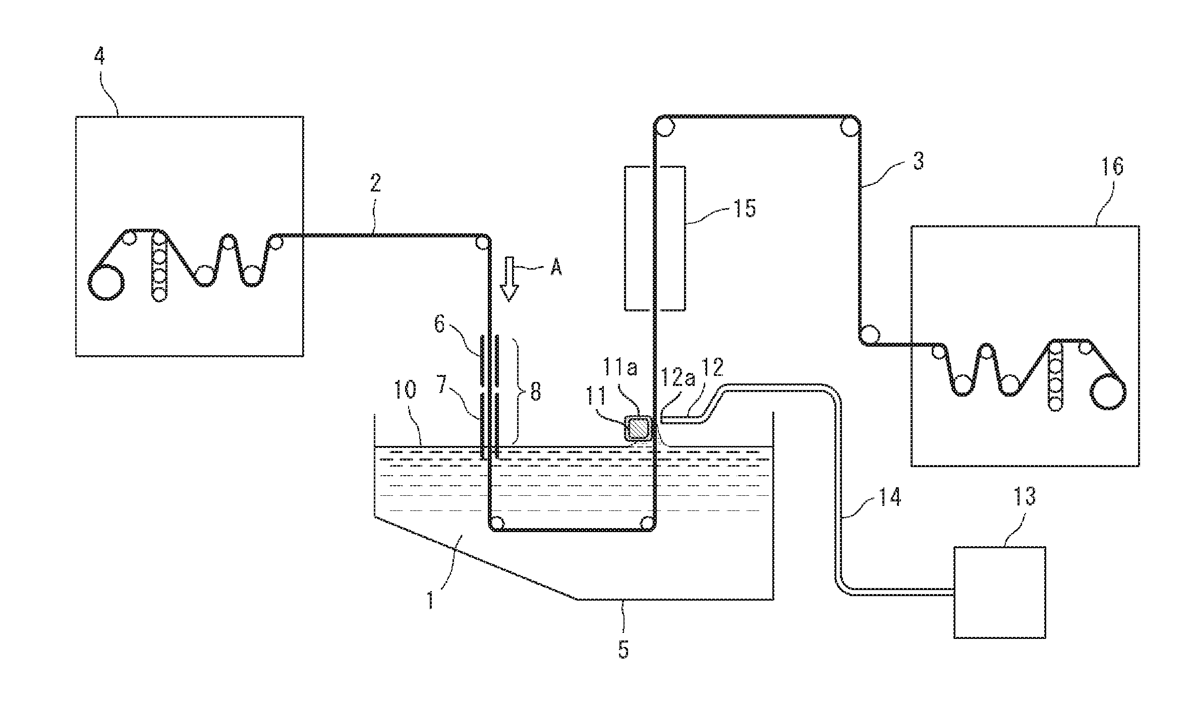
Provided is a method for producing a molten aluminum-plated steel wire in which a steel wire (2) is immersed in a molten aluminum plating bath (1), the resulting molten aluminum-plated steel wire (3) is subsequently pulled up from the molten aluminum plating bath (1) and a stabilizing member (11) is brought into contact with the bath surface (10) of the molten aluminum plating bath (1) and the molten aluminum-plated steel wire (3) at the boundary between the molten aluminum-plated steel wire (3) and the bath surface (10) of the molten aluminum plating bath (1), a nozzle (12) for blowing an inert gas is arranged in a position facing the stabilizing member (11) with the molten aluminum-plated steel wire (3) therebetween, and an inert gas is blown from the tip (12a) of the nozzle (12) toward the boundary at a pressure of 0.1-20 kPa.
| Inventors: | MIONO; Tadaaki; (Tokyo, JP) ; KAMOSHIDA; Shinichi; (Tokyo, JP) ; HATTORI; Yasunori; (Tokyo, JP) | ||||||||||
| Applicant: |
|
||||||||||
|---|---|---|---|---|---|---|---|---|---|---|---|
| Assignee: | NISSHIN STEEL CO., LTD. Tokyo JP |
||||||||||
| Family ID: | 59964825 | ||||||||||
| Appl. No.: | 16/088469 | ||||||||||
| Filed: | March 30, 2017 | ||||||||||
| PCT Filed: | March 30, 2017 | ||||||||||
| PCT NO: | PCT/JP2017/013474 | ||||||||||
| 371 Date: | September 26, 2018 |
| Current U.S. Class: | 1/1 |
| Current CPC Class: | C23C 2/12 20130101; C23C 2/18 20130101; C22C 21/02 20130101; C23C 2/22 20130101; C23C 2/185 20130101; C23C 2/38 20130101 |
| International Class: | C23C 2/38 20060101 C23C002/38; C23C 2/12 20060101 C23C002/12; C23C 2/18 20060101 C23C002/18 |
Foreign Application Data
| Date | Code | Application Number |
|---|---|---|
| Mar 31, 2016 | JP | 2016-070331 |
Claims
1. A method for producing a hot-dip aluminum-coated steel wire by dipping a steel wire in molten aluminum, and then continuously drawing up the steel wire from the molten aluminum, to produce a hot-dip aluminum-coated steel wire, which comprises the steps of: dipping a steel wire in molten aluminum, and then drawing up a resulting hot-dip aluminum-coated steel wire from the molten aluminum; contacting a stabilizing member with the surface of the molten aluminum and the hot-dip aluminum-coated steel wire at the boundary between the hot-dip aluminum-coated steel wire and the surface of the molten aluminum; disposing a nozzle for blowing an inert gas at a place where the nozzle is faced to the stabilizing member through the hot-dip aluminum-coated steel wire; and blowing the inert gas from the tip of the nozzle to the above-mentioned boundary at a pressure of 0.1 to 20 kPa.
2. The method for producing a hot-dip aluminum-coated steel wire according to claim 1, wherein the steel wire is a steel wire made of stainless steel or carbon steel.
3. The method for producing a hot-dip aluminum-coated steel wire according to claim 1, wherein the temperature of the molten aluminum is adjusted to a temperature 20.degree. C. or more higher than the melting point of the molten aluminum.
4. The method for producing a hot-dip aluminum-coated steel wire according to claim 2, wherein the temperature of the molten aluminum is adjusted to a temperature 20.degree. C. or more higher than the melting point of the molten aluminum.
Description
TECHNICAL FIELD
[0001] The present invention relates to a method for producing a hot-dip aluminum-coated steel wire. More particularly, the present invention relates to a method for producing a hot-dip aluminum-coated steel wire which can be suitably used in, for example, a wire harness of an automobile, and the like.
[0002] In the present description, the hot-dip aluminum-coated steel wire means a steel wire which has been plated with aluminum by dipping a steel wire in molten aluminum, and then continuously drawing up the steel wire from the molten aluminum. In addition, the molten aluminum means a plating liquid of molten aluminum.
BACKGROUND ART
[0003] A copper wire has been hitherto used as an electric wire which is used in a wire harness of an automobile, and the like. In recent years, it has been desired to develop an electric wire in which a metal wire having a weight lighter than the copper wire is used in view of requirement of weight saving.
[0004] As an electric wire having a weight lighter than the copper wire, a hot-dip Al-coated steel wire obtained by plating a steel wire with hot-dip aluminum has been proposed (for example, see claim 1 of Patent Literature 1). The above-mentioned hot-dip Al-coated steel wire has been produced by dipping a steel wire or a steel wire having a zinc plated layer or a nickel plated layer on its surface in molten aluminum, and then continuously drawing up the steel wire from the molten aluminum to the air (see, for example, paragraph [0024] of Patent Literature 1).
[0005] In addition, as a method for producing a hot-dip aluminum-coated steel wire, there has been proposed a method for producing a hot-dip aluminum-coated steel wire by dipping a steel wire in molten aluminum, and then continuously drawing up the steel wire from the molten aluminum, to produce a hot-dip aluminum-coated steel wire, which includes the steps of dipping a steel wire in molten aluminum; and then contacting a stabilization member with a surface of the molten aluminum and the steel wire when the steel wire is drawn up from the molten aluminum; providing a nozzle having an inner diameter of 1 mm to 15 mm so that a tip of the nozzle is positioned at a place apart from the steel wire in a distance of 1 mm to 50 mm, and blowing an inactive gas having a temperature of 200 to 800.degree. C. toward the boundary between the steel wire and the surface of the molten aluminum in a volume flow rate of 2 to 200 L/min (see, for example, Patent Literature 2). According to the above-mentioned method for producing a hot-dip aluminum-coated steel wire, there can be exhibited excellent effects such that a hot-dip aluminum-coated steel wire having a uniform wire diameter and hardly having an aluminum lump can be efficiently produced.
[0006] However, when a hot-dip aluminum-coated steel wire is produced by the above-mentioned method for producing a hot-dip aluminum-coated steel wire, there is a possibility that a thin part of a plating layer is generated on the hot-dip aluminum-coated steel wire. When the hot-dip aluminum-coated steel wire having a thin part of a plating layer is subjected to a wire-drawing process, there is a possibility that the steel wire included in the hot-dip aluminum-coated steel wire is exposed to the outside, and that the hot-dip aluminum-coated steel wire is broken due to fluctuation of drawing resistance of the hot-dip aluminum-coated steel wire in the wire-drawing process.
PRIOR ART LITERATURES
Patent Literatures
[0007] Patent Literature 1: Japanese Patent Unexamined Publication No. 2014-185355
[0008] Patent Literature 2: Japanese Patent Unexamined Publication No. 2015-134961
SUMMARY OF THE INVENTION
Problems to be Solved by the Invention
[0009] The present invention has been made in view of the above-mentioned prior art. An object of the present invention is to provide a method for producing a hot-dip aluminum-coated steel wire, which can efficiently provide a hot-dip aluminum-coated steel wire, and which hardly forms a thin part of a plating film and an aluminum lump on the surface of the plating film.
Means for Solving the Problems
[0010] The present invention relates to:
(1) a method for producing a hot-dip aluminum-coated steel wire by dipping a steel wire in molten aluminum, and then continuously drawing up the steel wire from the molten aluminum, to produce a hot-dip aluminum-coated steel wire, which includes the steps of: dipping a steel wire in molten aluminum; thereafter drawing up a resulting hot-dip aluminum-coated steel wire from the molten aluminum; contacting a stabilizing member with the surface of the molten aluminum and the hot-dip aluminum-coated steel wire at the boundary between the hot-dip aluminum-coated steel wire and the surface of the molten aluminum; disposing a nozzle for blowing an inert gas at a place where the nozzle is faced to the stabilizing member through the hot-dip aluminum-coated steel wire; and blowing the inert gas from the tip of the nozzle to the above-mentioned boundary at a pressure of 0.1 to 20 kPa; (2) the method for producing a hot-dip aluminum-coated steel wire according to the above item (1), wherein the steel wire is a steel wire made of stainless steel or carbon steel; and (3) the method for producing a hot-dip aluminum-coated steel wire according to the above item (1) or (2), wherein the temperature of the molten aluminum is adjusted to a temperature 20.degree. C. or more higher than the melting point of the molten aluminum.
Effects of the Invention
[0011] According to the method for producing a hot-dip aluminum-coated steel wire of the present invention, there can be exhibited excellent effects such that a hot-dip aluminum-coated steel wire can be efficiently produced so that a plating film having a thin portion of the plating film is hardly formed, and an aluminum lump is hardly deposited on the surface of the plating film.
BRIEF DESCRIPTION OF THE DRAWINGS
[0012] FIG. 1 is a schematic view showing one embodiment of a method for producing a hot-dip aluminum-coated steel wire according to the present invention.
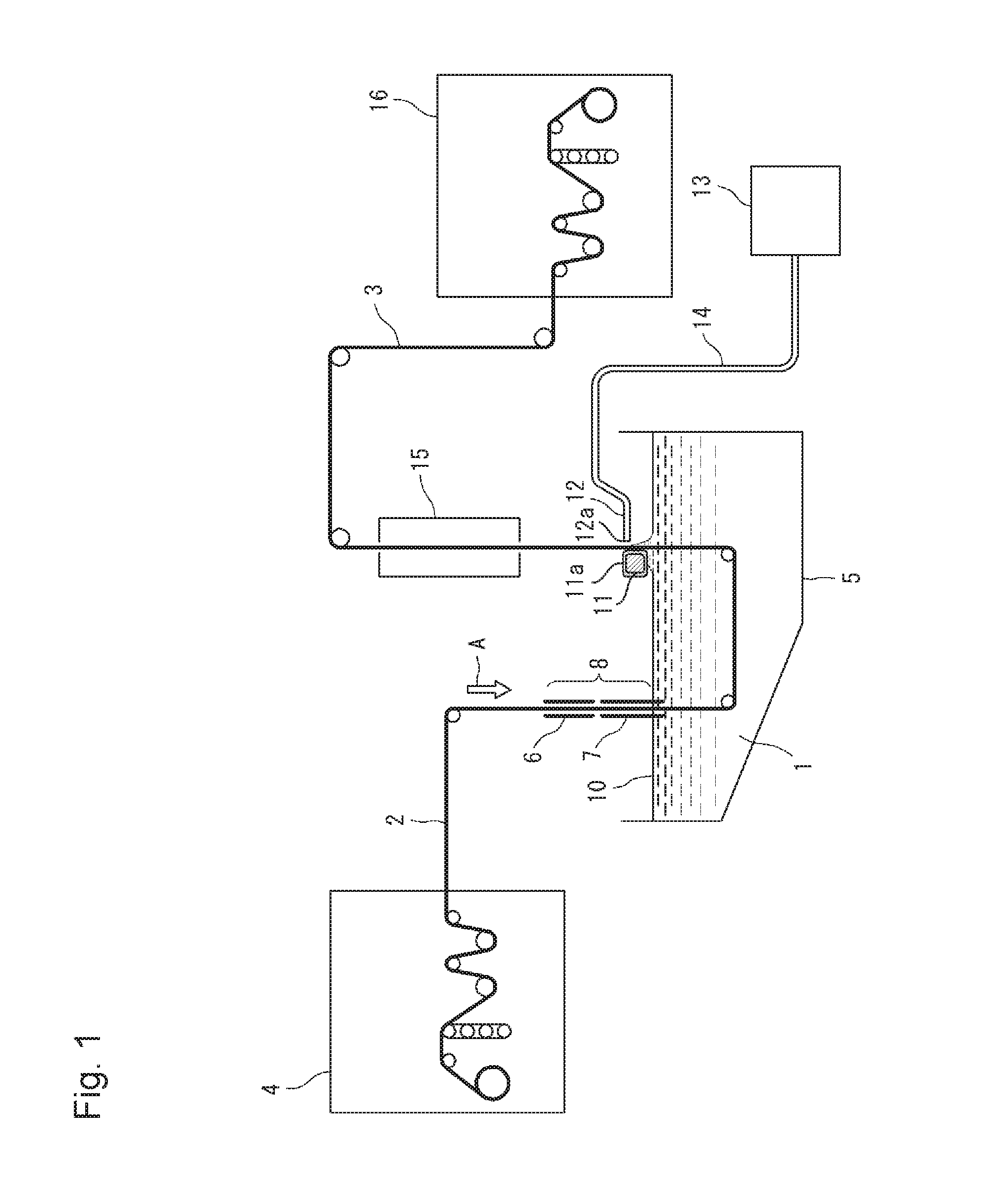
[0013] FIG. 2 is a schematic cross-sectional view showing one embodiment of a steel wire-introducing controller shown in FIG. 1.
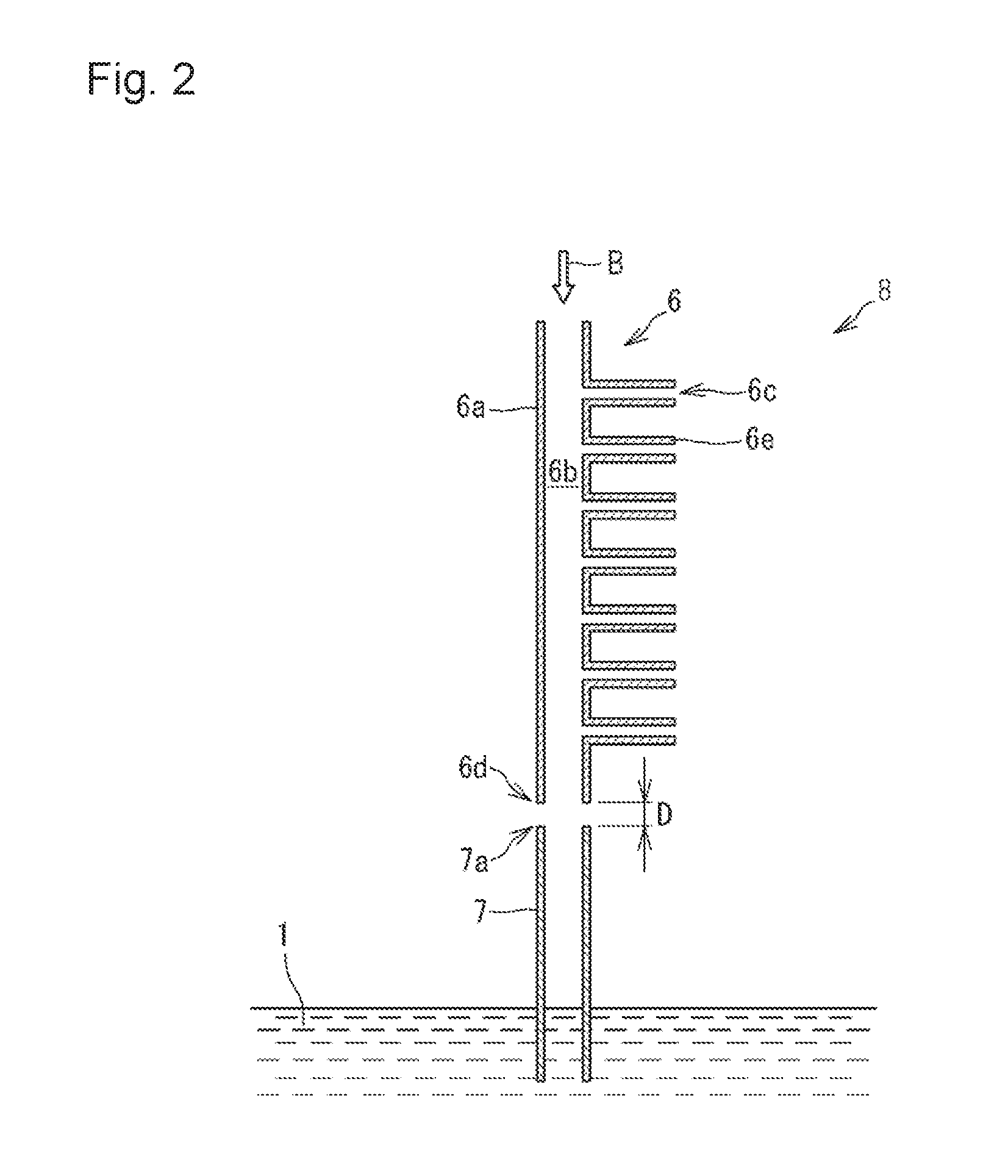
[0014] FIG. 3 is a schematic cross-sectional view showing one embodiment of a liquid surface-controlling device used in the steel wire-introducing controller shown in FIG. 1 and FIG. 2.
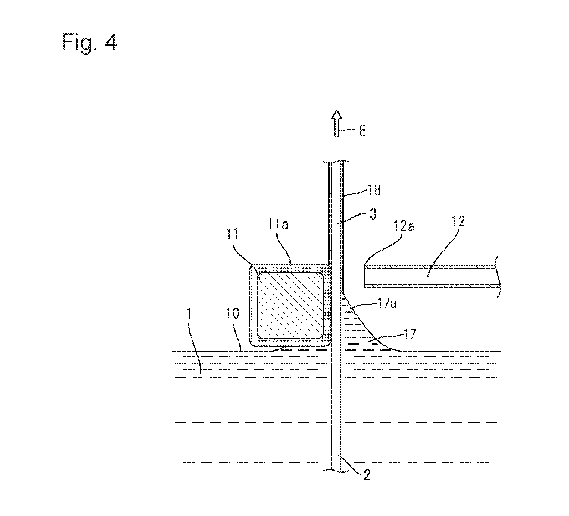
[0015] FIG. 4 is a schematic explanatory view showing the boundary between a steel wire and a surface of molten aluminum when the steel wire is drawn up from the molten aluminum in the method for producing a hot-dip aluminum-coated steel wire according to the present invention.
[0016] FIG. 5 is a schematic explanatory view showing one embodiment of a method for determining an average thickness of a plating film of a hot-dip aluminum-coated steel wire obtained in each of working examples and comparative examples.
MODE FOR CARRYING OUT THE INVENTION
[0017] The method for producing a hot-dip aluminum-coated steel wire according to the present invention includes a process for dipping a steel wire in molten aluminum, and then continuously drawing up the steel wire from the molten aluminum, to produce a hot-dip aluminum-coated steel wire. The method includes one of characteristics in dipping the steel wire in molten aluminum; thereafter drawing up a resulting hot-dip aluminum-coated steel wire from the molten aluminum; contacting a stabilizing member with the surface of the molten aluminum and the hot-dip aluminum-coated steel wire at the boundary between the hot-dip aluminum-coated steel wire and the surface of the molten aluminum; disposing a nozzle for blowing an inert gas at a place where the nozzle is faced to the stabilizing member through the hot-dip aluminum-coated steel wire; and blowing the inert gas from the tip of the nozzle to the above-mentioned boundary at a pressure of 0.1 to 20 kPa, as mentioned above.
[0018] According to the method for producing a hot-dip aluminum-coated steel wire of the present invention, since the above-mentioned operations are employed in the method, a hot-dip aluminum-coated steel wire can be efficiently produced so that a plating film having a thin portion of the plating film is hardly formed, and an aluminum lump is hardly deposited on the surface of the plating film.
[0019] Hereinafter, the method of producing a hot-dip aluminum-coated steel wire according to the present invention will be described based on drawings. However, the present invention is not limited only to those embodiments described in the drawings.
[0020] FIG. 1 is a schematic explanatory view showing one embodiment of the method for producing a hot-dip aluminum-coated steel wire according to the present invention.
[0021] According to the method of producing a hot-dip aluminum-coated steel wire of the present invention, a steel wire 2 is dipped in molten aluminum 1, and then the steel wire 2 is continuously drawn up from the molten aluminum 1, to produce a hot-dip aluminum-coated steel wire 3.
[0022] Examples of steel used in the steel wire 2 include, for example, stainless steel, carbon steel and the like, and the present invention is not limited only to those exemplified ones.
[0023] The stainless steel is an alloy steel containing 10% by mass or more of chromium (Cr). Examples of the stainless steel include, for example, austenitic steel materials, ferritic steel materials and martensitic steel materials defined in JIS G4309, and the like, and the present invention is not limited only to those exemplified ones. Specific examples of the stainless steel include stainless steel in which an austenitic phase is generally considered to be metastable, such as SUS301 and SUS304; stable austenitic stainless steel such as SUS305, SUS310 and SUS316; ferritic stainless steel such as SUS405, SUS410L, SUS429, SUS430, SUS434, SUS436, SUS444 and SUS447; martensitic stainless steel such as SUS403, SUS410, SUS416, SUS420, SUS431 and SUS440; chromium-nickel-manganese-based stainless steel classified into SUS200 series, and the like, and the present invention is not limited only to those exemplified ones.
[0024] The carbon steel contains 0.02% by mass or more of carbon (C). Examples of the carbon steel include, for example, high carbon steel wire rods defined in JIS G3506, low carbon steel wire rods defined in JIS G3505, and the like, and the present invention is not limited only to those exemplified ones. Specific examples of the carbon steel include high carbon steel, low carbon steel and the like, and the present invention is not limited only to those exemplified ones.
[0025] Among the above-mentioned steels, the stainless steel and the carbon steel are preferred, and the stainless steel is more preferred, from the viewpoint of increase in tensile strength of the hot-dip aluminum-coated steel wire 3.
[0026] The diameter of the steel wire 2 is not particularly limited. It is preferred that the diameter of the steel wire 2 is appropriately controlled in accordance with uses of the hot-dip aluminum-coated steel wire 3. For example, when the hot-dip aluminum-coated steel wire 3 is used in a wire harness of an automobile and the like, it is preferred that the diameter of the steel wire 2 is usually 0.05 to 0.5 mm or so.
[0027] The steel wire 2 can be previously degreased before carrying out hot-dip aluminum plating of the steel wire 2. The degreasing of the steel wire 2 can be carried out by, for example, a method which includes dipping the steel wire 2 in an alkaline degreasing liquid, taking out the steel wire 2 from the alkaline degreasing liquid, neutralizing the alkaline degreasing liquid deposited on the steel wire 2 by washing with water, and washing again the steel wire 2 with water; a method which includes carrying out electrolytic degreasing of the steel wire 2 by passing electricity through the steel wire 2 under a condition so that the steel wire 2 is dipped in an alkaline degreasing liquid; and the like. Incidentally, the above-mentioned alkaline degreasing liquid may contain a surfactant from the viewpoint of improvement in degreasing property.
[0028] In FIG. 1, the steel wire 2 is provided from a delivery device 4 of the steel wire 2. Thereafter, the steel wire 2 is continuously transferred in the direction of arrow A, and dipped in the molten aluminum 1 charged in a plating bath 5.
[0029] Incidentally, when the steel wire 2 is made of carbon steel, it is preferred that degreasing of the steel wire 2 is carried out between the delivery device 4 and the molten aluminum 1, because there is a possibility that rust is generated on the surface of the steel wire 2 due to degreasing of the steel wire 2 until hot-dip aluminum plating of the steel wire 2 is carried out. The degreasing of the steel wire 2 made of carbon steel can be carried out in the same manner as the above-mentioned method for degreasing the steel wire 2.
[0030] The molten aluminum 1 may contain only aluminum. Alternatively, the molten aluminum 1 may contain an element other than aluminum as occasion demands within a scope which would not hinder an object of the present invention. Examples of the element other than aluminum include, for example, nickel, chromium, zinc, silicon, copper, iron and the like, and the present invention is not limited only to those exemplified ones. When the element other than aluminum is contained in aluminum, mechanical strength of a plating film can be increased, and moreover, tensile strength of the hot-dip aluminum-coated steel wire 3 can be increased. Among the elements other than aluminum, although the kind of the element depends on the kind of the steel wire 2, silicon is preferred from the viewpoint of suppression of generation of a brittle iron-aluminum alloy layer between iron contained in the steel wire 2 and aluminum contained in the plating film, increase in mechanical strength of the plating film and lowering in melting point of the molten aluminum 1, thereby increase in efficiency of plating of the steel wire 2.
[0031] The plating film (not shown in the figure) made of aluminum or an aluminum alloy has been formed on the surface of the hot-dip aluminum-coated steel wire 3. The lower limit of the content of the above-mentioned element other than aluminum in the plating film is 0% by mass. From the viewpoint of sufficient exhibition of properties based on the element other than aluminum, the lower limit thereof is preferably 0.3% by mass or more, more preferably 0.5% by mass or more, and furthermore preferably 1% by mass or more. From the viewpoint of suppression of galvanic corrosion caused by contacting with an aluminum wire, the upper limit thereof is preferably 50% by mass or less, more preferably 20% by mass or less, and furthermore preferably 15% by mass or less.
[0032] Incidentally, an element such as nickel, chrome, zinc, copper or iron is possibly inevitably incorporated in the molten aluminum 1.
[0033] The lower limit of the temperature of the molten aluminum 1 is a temperature which is equal to or higher than the melting temperature of the molten aluminum 1 when the hot-dip aluminum-coated steel wire 3 is produced, and is usually a temperature which is equal to or higher than the melting temperature of the molten aluminum 1 at atmospheric pressure.
[0034] When the temperature of the molten aluminum 1 is adjusted to a temperature 20.degree. C. or more higher than the melting point of the molten aluminum 1, the hot-dip aluminum-coated steel wire 3 can be produced so that a plating film having a thin portion of the plating film is hardly formed, and an aluminum lump is hardly deposited on the surface of the plating film, even when the temperature of the inert gas discharged from the tip 12a of the nozzle 12 is room temperature (for example, room temperature of 0.degree. C. or higher). Accordingly, the lower limit of the temperature of the molten aluminum 1 is adjusted preferably to a temperature 20.degree. C. or more higher than the melting point of the molten aluminum 1, and more preferably to a temperature 25.degree. C. or more higher than the melting point of the molten aluminum 1, from the viewpoint of production of the hot-dip aluminum-coated steel wire 3 so that a plating film having a thin portion of the plating film is hardly formed, and an aluminum lump is hardly deposited on the surface of the plating film without an operation for heating the inert gas discharged from the tip 12a of the nozzle 12.
[0035] The upper limit of the temperature of the molten aluminum 1 is preferably 800.degree. C. or lower, more preferably 780.degree. C. or lower, and further preferably 750.degree. C. or lower, from the viewpoint of improvement in thermal efficiency.
[0036] In addition, it is preferred that the temperature of the molten aluminum 1 is 650 to 750.degree. C. from the viewpoint of efficient production of the hot-dip aluminum-coated steel wire 3 so that a plating film having a thin portion of the plating film is hardly formed, and an aluminum lump is hardly deposited on the surface of the plating film.
[0037] Incidentally, the temperature of the molten aluminum 1 is a temperature as determined by dipping a temperature sensor produced by inserting a thermocouple into a protective pipe for protecting the thermocouple in the molten aluminum 1 at a depth of about 300 mm from the surface of the molten aluminum 1 near the steel wire 2 which is drawn up from the molten aluminum 1.
[0038] In the present invention, it is preferred that the steel wire 2 is passed through a steel wire-introducing controller 8 for aluminum plating having a heating device 6 for heating the steel wire 2 and a liquid surface-controlling device 7 for preventing the surface of the steel wire 2 from adhesion of an oxide film, prior to dipping of the steel wire 2 in the molten aluminum 1, from the viewpoint of efficient production of the hot-dip aluminum-coated steel wire 3 so that a plating film having a thin portion of the plating film is hardly formed, and an aluminum lump is hardly deposited on the surface of the plating film.
[0039] As the steel wire-introducing controller 8, there can be cited, for example, a steel wire-introducing controller 8 shown in FIG. 2 and the like, and the present invention is not limited to the exemplified one. FIG. 2 is a schematic cross-sectional view showing one embodiment of the steel wire-introducing controller 8 shown in FIG. 1. The steel wire-introducing controller 8 has the heating device 6 and the liquid surface-controlling device 7.
[0040] As shown in FIG. 2, the heating device 6 has a heating device body 6a having a cylindrical shape, made of, for example, steel such as stainless steel. An inside 6b of the heating device body 6a is vacant in order to pass through the steel wire 2 in a direction of arrow B. A branch pipe 6e having a heating gas inlet 6c for introducing a heating gas is provided at the side surface of the heating device body 6a.
[0041] The heating gas which is introduced into the heating device 6 includes, for example, air, inert gases such as nitrogen gas, argon gas and helium gas, and the like, and the present invention is not limited only to those exemplified ones. Among them, the inert gases are preferred from the viewpoint of prevention of oxidization of the molten aluminum 1 existing in the liquid surface-controlling device 7 by ventilating the heating gas exhausted from the lower end 6d of the heating device 6 to an introducing port equipped at the upper end 7a of the liquid surface-controlling device 7 which is provided below of the heating device 6, to make the inside of the liquid surface-controlling device 7 an inert gas atmosphere. The temperature of the heating gas cannot be absolutely determined because the temperature of the heating gas differs depending on the kind and diameter of the steel wire 2 being used, conditions such as a line speed of the steel wire 2 and a flow rate of the heating gas, and the like. Accordingly, it is preferred that the temperature of the heating gas is controlled so that the steel wire 2 is appropriately heated under the above conditions.
[0042] The heating temperature of the steel wire 2 is preferably 60.degree. C. or higher, more preferably 80.degree. C. or higher, furthermore preferably 150.degree. C. or higher, and still more preferably 200.degree. C. or higher, from the viewpoint of efficient production of the hot-dip aluminum-coated steel wire 3. The upper limit of the heating temperature cannot be absolutely determined because the upper limit of the heating temperature differs depending on the kind of the steel wire 2 and the like. It is preferred that the upper limit of the heating temperature is usually preferably 1000.degree. C. or lower, more preferably 900.degree. C. or lower, and furthermore preferably 800.degree. C. or lower, in consideration of energy efficiency. Incidentally, the above-mentioned heating temperature is a temperature as determined in accordance with a method described in the following working examples.
[0043] The length of the heating device body 6a shown FIG. 2 can be a length where the steel wire 2 is heated to a predetermined temperature, and is not particularly limited. As one example of the length thereof, for example, the length can be 1 m to 5 m or so. In addition, it is preferred that a diameter of the inside 6b of the heating device body 6a cannot be absolutely determined, because the diameter of the inside 6b differs depending on the diameter and kind of the steel wire 2 being used. The diameter of the inside 6b of the heating device body 6a is usually about 1.5 times to about 50 times larger than the diameter of the steel wire 2. As one example of the diameter of the inside 6b of the heating device body 6a, it is preferred that the diameter of the inside 6b of the heating device body 6a is, for example, 0.3 mm to 10 mm or so when the steel wire 2 having a diameter of 0.2 mm is used.
[0044] The branch pipe 6e having the heating gas inlet 6c is provided on the side surface of the heating device body 6a. The steel wire 2 passing through the heating device 6 can be heated by introducing the heating gas into the heating gas inlet 6c of the branch pipe 6e. Alternatively, the steel wire 2 can be heated by providing a heater (not shown in the figure) inside the branch pipe 6e, and heating the heating gas passing through the branch pipe 6e with the heater. In the embodiment shown in FIG. 2, seven branch pipes 6e are provided. However, the number of the branch pipe 6e is not particularly limited, and the number of the branch pipe 6e can be only one, or can be 2 to 10 or so.
[0045] In the embodiment shown in FIG. 2, a gap D is provided between a lower end 6d of the heating device 6 and an upper end 7a of the liquid surface-controlling device 7 provided below the heating device 6. It is preferred that the above-mentioned gap D is 3 mm to 10 mm or so from the viewpoint of efficient discharge of the heating gas from the gap D. Incidentally, there is no necessity that the above-mentioned gap D is always provided. The heating device 6 can be separately produced from the liquid surface-controlling device 7, and the heating device 6 and the liquid surface-controlling device 7 can be united into one body by, for example, screw mating and the like. When the heating device 6 and the liquid surface-controlling device 7 are united into one body, an exhaust port (not shown in the figure) for exhausting the heating gas, which is passed through the inside of the heating device 6, can be provided on the side surface of the heating device 6 or the liquid surface-controlling device 7 as occasion demands.
[0046] Incidentally, a heating device such as an electric heating device or an induction heating device can be used in place of the heating device 6 in the present invention.
[0047] As the liquid surface-controlling device 7, there can be cited, for example, a liquid surface-controlling device 7 shown in FIG. 3 and the like, and the present invention is not limited to the exemplified one. FIG. 3 is a schematic cross-sectional view showing one embodiment of the liquid surface-controlling device 7 used in the steel wire-introducing controller 8 shown in FIG. 1 and FIG. 2.
[0048] As shown in FIG. 3, the liquid surface-controlling device 7 includes a tubular body 9 having a through hole 9a for introducing the steel wire 2 into the tubular body 9 in the direction of arrow C. The total length L of the liquid surface-controlling device 7 is preferably 30 mm to 500 mm, more preferably 40 mm to 300 mm, and furthermore preferably 50 mm to 100 mm.
[0049] The tubular body 9 has a dipping region 9b for dipping the tubular body 9 in the molten aluminum 1 from one end part of the tubular body 9 which is to be dipped in the molten aluminum 1 to a virtual line P shown in FIG. 3 along a longitudinal direction of the tubular body 9. The length of the dipping region 9b is usually preferably 2 mm to 20 mm, and more preferably 5 mm to 15 mm.
[0050] The length of the tubular body 9 along the longitudinal direction of the tubular body 9 where the tubular body 9 is not dipped in the molten aluminum 1 is usually preferably 5 mm or more, and more preferably 10 mm or more.
[0051] A value of a ratio of an area of the opening part of the through hole 9a of the tubular body 9 to an area of the cross section of the steel wire 2 used in hot-dip aluminum plating, which is a so-called cross-section of the steel wire 2 [area of the opening part of the through hole 9a of the tubular body 9/area of the cross section of the steel wire 2] is preferably 3 or more from the viewpoint of smooth introduction of the steel wire 2 into the through hole 9a of the tubular body 9. The value of the ratio is preferably 4000 or less, more preferably 3000 or less, furthermore preferably 2000 or less, and still more preferably 1000 or less, from the viewpoint of prevention of the steel wire 2 from adhesion of an oxide film.
[0052] The shape of the opening part of the through hole 9a of the tubular body 9 is arbitrary, and can be circular or other shape. The gap (clearance) between the opening part of the through hole 9a of the tubular body 9 and the steel wire 2 is preferably 10 .mu.m or more, more preferably 20 .mu.m or more, furthermore preferably 50 .mu.m or more, and still more preferably 100 .mu.m or more, from the viewpoint of avoidance of sliding of an inner wall of the through hole 9a of the tubular body 9 and the steel wire 2.
[0053] Incidentally, the opening parts of the through hole 9a provided in the tubular body 9 are an opening part 9d provided at the introducing port 9c for introducing the steel wire 2 from one end of the tubular body 9, and an opening part 9f provided at a discharge port 9e for discharging the steel wire 2 from another end of the tubular body 9 as shown in FIG. 3. The area and shape of the opening part 9d can be the same as those of the opening part 9f. Alternatively, the area and shape of the opening part 9d can be different from those of the opening part 9f. However, it is preferred that the area and shape of the opening part 9d are the same as those of the opening part 9f, respectively, as shown in FIG. 3 from the viewpoint that the steel wire 2 is smoothly passed through the through hole 9a of the tubular body 9, that sliding of the inner wall of the through hole 9a of the tubular body 9 with the steel wire 2 is avoided, and that the hot-dip aluminum-coated steel wire 3 having a plating film over the whole surface is efficiently produced.
[0054] The steel wire 2 passed through the steel wire-introducing controller 8 as occasion demands is dipped in the molten aluminum 1.
[0055] The line speed of the steel wire 2 is 100 m/min or more from the viewpoint of efficient production of the hot-dip aluminum-coated steel wire 3, and is preferably 1000 m/min or lower, and more preferably 800 mm/min or lower, from the viewpoint of prevention of scatter of an oxide film formed on the surface of the molten aluminum 1, and efficient production of the hot-dip aluminum-coated steel wire 3 having little oxide film adhered to its surface.
[0056] The period of time for dipping the steel wire 2 in the molten aluminum 1 (plating period of time) is controlled so that the plating film formed on the surface of the steel wire 1 has a predetermined thickness. The period of time for dipping the steel wire 2 in the molten aluminum 1 (plating period of time) cannot be absolutely determined because the plating period of time differs depending on a required thickness of the plating film, a temperature of the molten aluminum 1 and the like. The plating period of time is usually 0.3 seconds to 1 second or so.
[0057] Next, as shown in FIG. 1, the steel wire 2 dipped in the molten aluminum 1 is drawn up from the surface 10 of the molten aluminum 1, to form a plating film made of the molten aluminum 1 on the surface of the steel wire 2, and thereby the hot-dip aluminum-coated steel wire 3 is obtained.
[0058] When the steel wire 2 is drawn up from the molten aluminum 1 in the direction of arrow E as illustrated in FIG. 4, the surface 10 of the molten aluminum is lifted upward together with the hot-dip aluminum-coated steel wire 3 which is drawn up from the molten aluminum 1, and thereby a meniscus 17 is formed. When the tip 17a of the meniscus 17 grows upward, the tip 17a of the meniscus 17 is solidified to form an aluminum lump. Accordingly, there is a possibility that the aluminum lump is adhered as a foreign substance to the surface of the plating film 18 of the hot-dip aluminum-coated steel wire 3.
[0059] In order to prevent the surface of the hot-dip aluminum-coated steel wire 3 from adhering the foreign substance such as an aluminum lump by inhibiting the excess growth of the tip 17a of the meniscus 17 upward, a stabilizing member 11 is contacted with the surface 10 of the molten aluminum 1 and the hot-dip aluminum-coated steel wire 3 at the boundary between the hot-dip aluminum-coated steel wire 3 drawn up from the molten aluminum 1 and the surface 10 of the molten aluminum 1, and a nozzle 12 for blowing an inert gas is disposed at a place where the nozzle 12 is faced to the stabilizing member 11 through the hot-dip aluminum-coated steel wire 3.
[0060] Incidentally, FIG. 4 is a schematic explanatory view showing the boundary between the steel wire 2 and the surface 10 of the molten aluminum 1 when the steel wire 2 is drawn up from the molten aluminum in the method for producing a hot-dip aluminum-coated steel wire according to the present invention.
[0061] The stabilization member 11 includes, for example, a square rod made of stainless steel, in which a heat-resistant cloth 11a is wound around the surface of the square rod, and the like. The heat-resistant cloth 11a includes, for example, woven fabric and non-woven fabric, containing a heat-resistant fiber such as a ceramic fiber, a carbon fiber, an aramid fiber or an imide fiber, and the present invention is not limited only to those exemplified ones. It is preferred that a virgin surface (new surface) of the heat-resistant cloth 11a is contacted with the hot-dip aluminum-coated steel wire 3 from the viewpoint of suppression of deposition of an aluminum lump on the surface of the hot-dip aluminum-coated steel wire 3.
[0062] It is preferred that the stabilization member 11 is contacted with both of the surface 10 of the molten aluminum 1 and the hot-dip aluminum-coated steel wire 3 at the same time. When the stabilization member 11 is contacted with both of the surface 10 of the molten aluminum 1 and the hot-dip aluminum-coated steel wire 3 at the same time as mentioned above, pulsation of the surface 10 of the molten aluminum 1 is suppressed, and thereby pulsation of the meniscus 17 is suppressed. Accordingly, a plating film 18 can be uniformly formed on the surface of the steel wire 2. Incidentally, when the stabilization member 11 is contacted with the hot-dip aluminum-coated steel wire 3, the stabilization member 11 can be slightly pressed toward the hot-dip aluminum-coated steel wire 3 as occasion demands in order to suppress minute vibration of the hot-dip aluminum-coated steel wire 3.
[0063] A nozzle 12 for blowing an inert gas is disposed at a place where the nozzle 12 is faced to the stabilizing member 11 through the hot-dip aluminum-coated steel wire 3. The tip 12a of the nozzle 12 is placed so that the inert gas is blown to the boundary between the hot-dip aluminum-coated steel wire 3 and the surface 10 of the molten aluminum 1. The distance (the shortest distance) from the hot-dip aluminum-coated steel wire 3 to the tip 12a of the nozzle 12 is preferably 1 mm or more from the viewpoint of avoidance of contact of the tip 12a of the nozzle 12 with the hot-dip aluminum-coated steel wire 3, and efficient production of the hot-dip aluminum-coated steel wire 3. The distance (the shortest distance) from the steel wire 2 to the tip 12a of the nozzle 12 is preferably 50 mm or less, more preferably 40 mm or less, still more preferably 30 mm or less, furthermore preferably 10 mm or less, and still furthermore preferably 5 mm or less, from the viewpoint of production of a hot-dip aluminum-coated steel wire 3 so that the plating film 18 having a thin portion of the plating film 18 is hardly formed, and an aluminum lump is hardly deposited on the surface of the plating film 18.
[0064] The inside diameter of the tip 12a of the nozzle 12 is preferably 1 mm or more, and more preferably 2 mm or more, from the viewpoint of efficient production of the hot-dip aluminum-coated steel wire 3 by accurately blowing the inert gas from the tip 12a of the nozzle 12 to the boundary between the hot-dip aluminum-coated steel wire 3 and the surface 10 of the molten aluminum 1. The inside diameter of the tip 12a of the nozzle 12 is preferably 15 mm or less, more preferably 10 mm or less, and furthermore preferably 5 mm or less, from the viewpoint of production of a hot-dip aluminum-coated steel wire 3 so that the plating film 18 having a thin portion of the plating film is hardly formed, and an aluminum lump is hardly deposited on the surface of the plating film 18.
[0065] The inert gas can be provided, for example, from an inert gas-providing apparatus 13 shown in FIG. 1 through a pipe 14 to the nozzle 12. Incidentally, a flow controller such as a valve (not shown in the figure) can be provided in the inert gas-providing apparatus 13 or the pipe 14 in order to control the flow rate of the inert gas.
[0066] The inert gas means a gas which is inert to molten aluminum. Examples of the inert gas include, for example, nitrogen gas, argon gas, helium gas and the like, and the present invention is not limited only to those exemplified ones. Among the inert gases, nitrogen gas is preferable. Incidentally, the inert gas may contain, for example, oxygen gas, carbon dioxide gas and the like within a scope which would not hinder an object of the present invention.
[0067] The pressure of the inert gas exhausted from the tip 12a of the nozzle 12 is controlled to 0.1 to 20 kPa. According to the present invention, when the steel wire 2 is dipped in the molten aluminum 1, and thereafter the hot-dip aluminum-coated steel wire 3 is drawn up from the molten aluminum 1, the pressure of the inert gas blown from the tip 12a of the nozzle 12 to the boundary between the hot-dip aluminum-coated steel wire 3 and the surface 10 of the molten aluminum 1 is controlled to 0.1 to 20 kPa at the tip 12a of the nozzle 12. Accordingly, the hot-dip aluminum-coated steel wire 3 can be produced so that the plating film 18 having a thin portion of the plating film is hardly formed, and an aluminum lump is hardly deposited on the surface of the plating film 18.
[0068] The pressure of the inert gas exhausted from the tip 12a of the nozzle 12 is 0.1 kPa or higher from the viewpoint of production of the hot-dip aluminum-coated steel wire 3 so that an aluminum lump is hardly deposited on the surface. The pressure of the inert gas is 20 kPa or lower, preferably 10 kPa or lower, and furthermore preferably 3 kPa or lower, from the viewpoint of production of the hot-dip aluminum-coated steel wire 3 so that the plating film 18 having a thin portion of the plating film is hardly formed, and an aluminum lump is hardly deposited on the surface of the plating film 18.
[0069] Incidentally, the pressure of the inert gas discharged from the tip 12a of the nozzle 12 is a pressure as determined by inserting a tube made of stainless steel having an inner diameter of 0.5 mm into the inert gas inside the nozzle 12 at a place apart from the tip 12a of the nozzle 12 in a distance of 2 mm so that the tip of the tube is opposed to the tip 12a of the nozzle 12, and determining the pressure of the inert gas applied to the tip of the tube by means of a pressure sensor.
[0070] The volume flow rate of the inert gas discharged from the tip 12a of the nozzle 12 is preferably 2 L (liter)/min or more, more preferably 5 L/min or more, and furthermore preferably 10 L/min or more, from the viewpoint of efficient inhibition of oxidization of the surface of the meniscus 17. The volume flow rate of the inert gas thereof is preferably 200 L/min or less, more preferably 150 L/min or less, and furthermore preferably 100 L/min or less, from the viewpoint of production of the hot-dip aluminum-coated steel wire 3 so that the plating film 18 having a thin portion of the plating film is hardly formed, and an aluminum lump is hardly deposited on the surface of the plating film 18.
[0071] The temperature of the inert gas discharged from the tip 12a of the nozzle 12 is preferably 10.degree. C. or higher, more preferably 20.degree. C. or higher, and furthermore preferably 30.degree. C. or higher, from the viewpoint of production of a hot-dip aluminum-coated steel wire 3 so that the plating film 18 having a thin portion of the plating film is hardly formed, and an aluminum lump is hardly deposited on the surface of the plating film 18. The temperature of the inert gas thereof is preferably 800.degree. C. or lower, more preferably 780.degree. C. or lower, and furthermore preferably 750.degree. C. or lower, from the viewpoint of increase in thermal efficiency.
[0072] Incidentally, the temperature of the inert gas discharged from the tip 12a of the nozzle 12 is a temperature as determined by inserting a thermocouple for measuring a temperature, such as a sheath thermocouple having a diameter of 1.6 mm into the inert gas at a place apart from the tip 12a of the nozzle 12 in a distance of 2 mm.
[0073] The line speed of the hot-dip aluminum-coated steel wire 3 drawing up from the surface 10 of the molten aluminum 1 is not particularly limited. The average thickness of the plating film 18 formed on the surface of the hot-dip aluminum-coated steel wire 3 can be controlled by appropriately controlling the line speed of the hot-dip aluminum-coated steel wire 3. Accordingly, it is preferred that the line speed of the hot-dip aluminum-coated steel wire 3 is appropriately adjusted in accordance with the average thickness of the plating film 18 formed on the surface of the hot-dip aluminum-coated steel wire 3.
[0074] Incidentally, a cooling device 15 can be provided above the nozzle 12 as occasion demands as illustrated in FIG. 1 in order to cool the hot-dip aluminum-coated steel wire 3 in the course of drawing up of the hot-dip aluminum-coated steel wire 3, and efficiently solidify the plating film 18 formed on the surface of the hot-dip aluminum-coated steel wire 3. The hot-dip aluminum-coated steel wire 3 can be cooled by blowing, for example, gas, liquid mist or the like to the hot-dip aluminum-coated steel wire 3 in the cooling device 15.
[0075] The hot-dip aluminum-coated steel wire 3 produced in the above can be collected by means of, for example, a winding device 16 or the like as shown in FIG. 1.
[0076] The average thickness of the plating film 18 formed on the surface of the hot-dip aluminum-coated steel wire 3 is preferably 5 .mu.m to 10 .mu.m or so from the viewpoint of suppression of exposure of the steel wire 2 included in the hot-dip aluminum-coated steel wire 3 to the air in carrying out a process such as a wire stranding process or a crimpling process, and increase in mechanical strength per unit diameter of the hot-dip aluminum-coated steel wire 3.
[0077] The minimum thickness of the thin part of the plating film 18 formed on the surface of the hot-dip aluminum-coated steel wire 3 is preferably 1 .mu.m or more, and more preferably 2 .mu.m or more, from the viewpoint of suppression of exposure of the steel wire 2 included in the hot-dip aluminum-coated steel wire 3 to the air in carrying out a process such as a wire stranding process or a crimpling process, and increase in mechanical strength per unit diameter of the hot-dip aluminum-coated steel wire 3.
[0078] Before the steel wire 2 is dipped in the molten aluminum 1, pre-plating of the surface of the steel wire 2 can be carried out from the viewpoint of efficient formation of the smooth plating film 18. The metal used in the pre-plating includes, for example, zinc, nickel, chrome, an alloy thereof and the like, and the present invention is not limited only to those exemplified ones. In addition, the plating layer 18 formed on the surface of the steel wire by pre-plating can be formed only by one layer. Alternatively, the plating layer 18 can be formed by plural plating layers made of the same kind or a different kind of a metal.
[0079] The hot-dip aluminum-coated steel wire 3 obtained in the above can be subjected to a drawing process using dies and the like as occasion demands so that the hot-dip aluminum-coated steel wire 3 has an appropriate outer diameter.
[0080] The hot-dip aluminum-coated steel wire 3 obtained by the method for producing a hot-dip aluminum-coated steel wire according to the present invention can be suitably used, for example, in a wire harness of an automobile, and the like.
Examples
[0081] Next, the present invention will be more specifically described based on working examples. However, the present invention is not limited only to those working examples.
[0082] Examples 1 to 66 and comparative examples 1 to 6 In each of working examples and each of comparative examples, a hot-dip aluminum-coated steel wire was produced based on the embodiment as illustrated in FIG. 1.
[0083] As a steel wire, a steel wire having a diameter shown in each table, and made of steel shown in each table was used. A steel wire on which surface was not treated by zinc plating (referred to as "non" in the column "pre Zn" in each table), or a steel wire having an average thickness of 5 .mu.m or less of a zinc plating layer (referred to as "existing" in the column "pre Zn" in each table) was used. In Table 5, the term "37A" listed in the column of "kind of steel" means a steel wire made of high carbon steel containing 0.37% by mass of carbon.
[0084] Incidentally, the steel wire on which surface was not treated by zinc plating was subjected to degreasing by dipping the steel wire in a degreasing liquid containing sodium orthosilicate and a surfactant, before the steel wire was dipped in the hot-dip aluminum.
[0085] In addition, before the steel wire was dipped in the molten aluminum, the steel wire was passed through the steel wire-introducing controller 8 shown in FIG. 2, and the steel wire was preheated to about 400.degree. C. by using the heating device 6. As a heating gas, nitrogen gas was used. Incidentally, a steel wire connected with a thermocouple was prepared, and the thermocouple was passed through the heating device 6 together with the steel wire, to determine the preheating temperature.
[0086] In addition, as the liquid surface-controlling device which was used in the steel wire-introducing controller 8 shown in FIG. 2, the liquid surface-controlling device 7 as shown in FIG. 3, in which the shape, size and area of the opening part 9d of the introducing port 9c of the through hole 9a of the tubular body 9 were the same as those of the opening part 9f of the discharge port 9e of the through hole 9a of the tubular body 9, was used. The value of the ratio of the area of the opening part of the through hole 9a of the tubular body 9 to the area of the cross section of the steel wire (area of the opening part of the through hole 9a of the tubular body 9/area of the cross section of the steel wire) was adjusted to 57. The steel wire was dipped in the molten aluminum through the liquid surface-controlling device 7 for 0.3 seconds to 1 second.
[0087] As the molten aluminum, molten aluminum (purity of aluminum: 99.7% or more, referred to as "Al" in the column "kind" of "hot-dip Al" in each table), molten aluminum containing 4% by mass of silicon (referred to as "4% Si" in the column "kind" of "hot-dip Al" in each table), molten aluminum containing 8% by mass of silicon (referred to as "8% Si" in the column "kind" of "hot-dip Al" in each table), molten aluminum containing 11% by mass of silicon (referred to as "11% Si" in the column "kind" of "hot-dip Al" in each table), or molten aluminum containing 13% by mass of silicon (referred to as "13% Si" in the column "kind" of "hot-dip Al" in each table) was used. The steel wire was dipped in the molten aluminum having a temperature shown in each table at a line speed (speed of drawing up of steel wire) shown in each table, and then the steel wire was drawn up from the molten aluminum.
[0088] At that time, a stabilizing member having a width of 40 mm was contacted with the surface of the molten aluminum and the hot-dip aluminum-coated steel wire which was drawn up from the molten aluminum at the boundary between the hot-dip aluminum-coated steel wire and the surface of the molten aluminum. Incidentally, as the stabilizing member, a square rod made of stainless steel of which surface was wound with a heat-resistant cloth was used. The length for contacting the hot-dip aluminum-coated steel wire with the heat-resistant cloth was adjusted to 5 mm.
[0089] In addition, a nozzle having an inner diameter shown in each table was arranged so that the tip of the nozzle was located at a place apart from the hot-dip aluminum-coated steel wire in a distance of 2 mm. An inert gas (nitrogen gas) of which temperature was controlled to a temperature shown in each table was discharged from the tip of the nozzle at a volume flow rate shown in each table, and was blown to the boundary between the hot-dip aluminum-coated steel wire and the surface of the molten aluminum at a pressure shown in each table.
[0090] The above operations were carried out, to obtain a hot-dip aluminum-coated steel wire having a plating film of an average thickness shown in each table and the minimum thickness of the thin part of the plating film shown in each table.
[0091] Incidentally, a method for determining the average thickness of the plating film is shown below. In addition, a method for determining the minimum thickness of the thin part of the plating film is described in the following paragraph "(2) Measuring of the minimum thickness of the thin part of the plating film".
[0092] [Method for Determining Average Thickness of Plating Film]
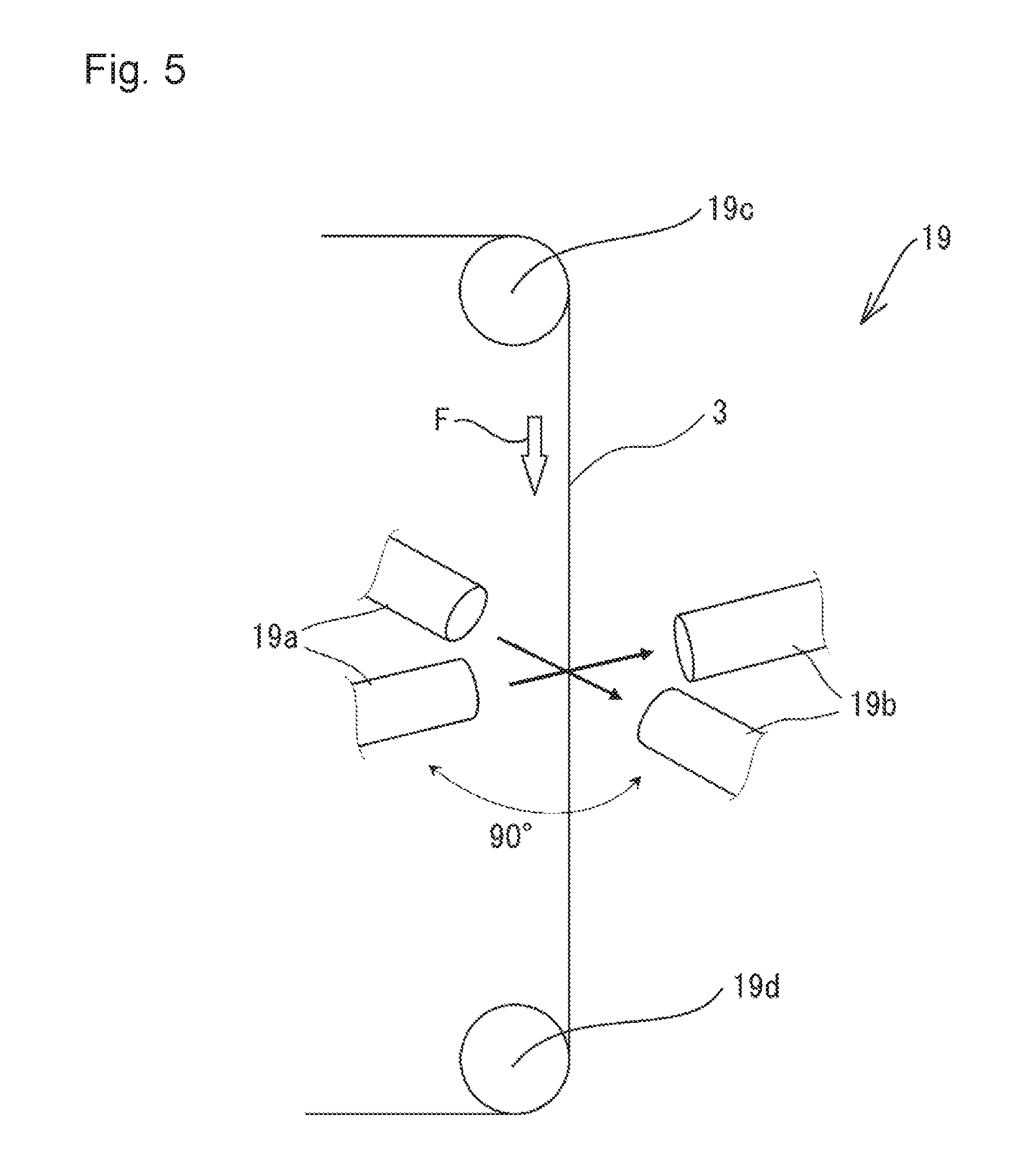
[0093] The average thickness of the plating film of the hot-dip aluminum-coated steel wire obtained in each working example and each comparative example was determined on the basis of an embodiment shown in FIG. 5. FIG. 5 is a schematic explanatory view showing one embodiment of the method for determining the average thickness of the plating film of the hot-dip aluminum-coated steel wire obtained in each working example and each comparative example.
[0094] As a device 19 for measuring a diameter of a steel wire by passing through the steel wire, a device for measuring a diameter having two optical micrometers each of which was commercially available from KEYENCE CORPORATION under the product number of LS-7000 was used as shown in FIG. 5. The device 19 for measuring a diameter had a pair of a pulley 19c and a pulley 19d which were positioned in a vertical direction against the steel wire, and a pair of a light emitting unit 19a and a light receiving unit 19b which were arranged in a horizontal direction at a central position between the pulley 19c and the pulley 19d. The light emitting unit 19a and the light receiving unit 19b were arranged so that the light emitting unit 19a and the light receiving unit 19b were opposed to each other. The light emitting unit 19a and the light receiving unit 19b adjacent each other were arranged so that an angle between the light emitting unit 19a and the light receiving unit 19b was 90.degree. as shown in FIG. 5.
[0095] While the hot-dip aluminum-coated steel wire 3 having a length of 100 m obtained in each working example or each comparative example was being run at a line speed of 100 m/min in a direction of arrow F between the pulley 19c and the pulley 19d, the outer diameter of the hot-dip aluminum-coated steel wire 3 was measured at an interval of about 1.4 mm in the longitudinal direction of the aluminum-plated steel wire 3 by means of the device 19 for measuring a diameter. Incidentally, the number of measurement points of the outer diameter was adjusted to about 71000 points.
[0096] Next, an average value of the outer diameters of the hot-dip aluminum-coated steel wire as measured in the above was calculated. The value of the diameter of the steel wire before forming a plating film (diameter of steel wire shown in the following each table) was subtracted from the average value, and an obtained value was divided by 2, to give an average thickness of a plating film. The results are shown in each table.
[0097] [Evaluation of Properties of Plating Film]
[0098] As the properties of the hot-dip aluminum-coated steel wire obtained in each working example or each comparative example, adhesion of aluminum lump and stability of the plating film at the thin part of the plating film having the minimum thickness were examined in accordance with the following methods. Its results are shown in each table.
[0099] (1) Adhesion of Aluminum Lump
[0100] A hot-dip aluminum-coated steel wire having a length of 300 m was run at a line speed of 100 m/min, and the outer diameter of the hot-dip aluminum-coated steel wire was measured over the whole length of the hot-dip aluminum-coated steel wire. At that time, whether or not a convex portion due to local increase in outer diameter exists was examined. Whether or not an aluminum lump exists in the convex portion due to local increase in outer diameter was observed with naked eyes, and adhesion of the aluminum lump was evaluated in accordance with the following evaluation criteria. Incidentally, the outer diameter of the hot-dip aluminum-coated steel wire was determined by means of an optical micrometer commercially available from KEYENCE CORPORATION under the product number of LS-7000.
[0101] [Evaluation Criteria]
.largecircle.: Adhesion of an aluminum lump is not observed. x: Adhesion of an aluminum lump is observed.
[0102] (2) Measuring of the Minimum Thickness of the Thin Part of the Plating Film
[0103] In order to measure the minimum thickness at the thin part of the plating film, the section of the hot-dip aluminum-coated steel wire was observed. More specifically, a specimen having a length of 300 mm was obtained by arbitrarily cutting the hot-dip aluminum-coated steel wire, and six test pieces were obtained from the specimen by cutting the specimen. Thereafter, the test pieces were embedded in a resin. The resulting embedded resin product was cut, and its cross section was polished, to expose the cross section of the hot-dip aluminum-coated steel wire. This cross section was observed with an optical microscope (magnification: 500 times), and the minimum thickness at the thin part of the plating film was measured. The minimum thickness at the thin part of the plating film was selected from the six test pieces, and the minimum thickness was regarded as the minimum thickness of thin part of plating film.
[0104] (3) Stability of Minimum Thickness of Thin Part of the Plating Film
[0105] The stability of the minimum thickness of the thin part of the plating film was evaluated based on the minimum thickness of the thin part of the plating film obtained in the above, and judged on the basis of the following evaluation criteria:
[0106] (Evaluation Criteria)
.circleincircle.: The minimum thickness of the thin part of the plating film is 2 .mu.m or more. .largecircle.: The minimum thickness of the thin part of the plating film is 1 .mu.m or more and less than 2 .mu.m. x: The minimum thickness of the thin part of the plating film is less than 1 .mu.m.
[0107] (4) Comprehensive Evaluation
[0108] In accordance with the results for evaluating the adhesion of aluminum lump and the stability of minimum thickness of thin part of the plating film, comprehensive evaluation was carried out on the basis of the following evaluation criteria:
[0109] (Evaluation Criteria)
.circleincircle.: The evaluation of the adhesion of aluminum lump is .largecircle., and the evaluation of the stability of minimum thickness of thin part of the plating film is .circleincircle. (Excellent). .largecircle.: The evaluation of the adhesion of aluminum lump and the evaluation of the stability of minimum thickness of thin part of the plating film are .largecircle., respectively (Good). x: The evaluation of x is included in any of the evaluation of the adhesion of aluminum lump and the evaluation of the stability of minimum thickness of thin part of the plating film (Failure).
TABLE-US-00001 TABLE 1 Hot-dip Al Nozzle Kind of steel wire Melting Temp. of Line Inner Inert gas Ex. Pre Diameter Kind of temp. hot-dip Al Speed diameter Temp. No. Zn (mm) steel Kind (.degree. C.) (.degree. C.) (m/min) (mm) (.degree. C.) 1 Non 0.20 SUS304 8% Si 615 700 300 7.6 780 2 Non 0.20 SUS304 8% Si 615 700 300 7.6 740 3 Non 0.20 SUS304 8% Si 615 700 300 4.0 720 4 Non 0.20 SUS304 8% Si 615 700 300 4.0 720 5 Non 0.20 SUS304 8% Si 615 700 300 3.0 720 6 Non 0.20 SUS304 8% Si 615 700 300 3.0 710 7 Non 0.20 SUS304 8% Si 615 700 300 3.0 670 8 Non 0.20 SUS304 8% Si 615 700 300 3.0 590 9 Non 0.20 SUS304 8% Si 615 700 300 2.4 660 10 Non 0.20 SUS304 8% Si 615 700 300 2.4 580 11 Non 0.20 SUS304 8% Si 615 700 300 2.4 580 12 Non 0.20 SUS304 8% Si 615 700 300 1.7 520 13 Non 0.20 SUS304 8% Si 615 700 300 1.7 520 14 Non 0.20 SUS304 8% Si 615 700 300 1.3 450 15 Non 0.20 SUS304 8% Si 615 700 300 1.1 400 16 Non 0.20 SUS304 8% Si 615 720 300 3.0 590 17 Non 0.20 SUS304 8% Si 615 720 300 2.4 660 18 Non 0.20 SUS304 8% Si 615 720 300 2.4 580 19 Non 0.20 SUS304 8% Si 615 680 300 3.0 590 20 Non 0.20 SUS304 8% Si 615 680 300 2.4 660 21 Non 0.20 SUS304 8% Si 615 680 300 2.4 580 Evaluation of Al-plated Plating film steel wire Inert gas Minimum Stability of Volume Average thickness of Adhesion of minimum Compre- Ex. flow rate Pressure thickness thin part aluminum thickness of hensive No. (L/min) (kPa) (.mu.m) (.mu.m) lump thin part evaluation 1 100 3.8 7.2 2.1 .largecircle. .circleincircle. .circleincircle. 2 50 0.75 7.4 2.9 .largecircle. .circleincircle. .circleincircle. 3 50 8.0 7.6 1.7 .largecircle. .largecircle. .largecircle. 4 10 0.38 7.2 3.2 .largecircle. .circleincircle. .circleincircle. 5 40 20.0 7.7 1.1 .largecircle. .largecircle. .largecircle. 6 30 10.0 7.7 1.6 .largecircle. .largecircle. .largecircle. 7 10 1.8 6.9 2.8 .largecircle. .circleincircle. .circleincircle. 8 2.5 0.12 8.1 4.8 .largecircle. .circleincircle. .circleincircle. 9 10 3.0 6.5 2.3 .largecircle. .circleincircle. .circleincircle. 10 5.0 0.92 7.8 3.3 .largecircle. .circleincircle. .circleincircle. 11 2.5 0.27 8.5 4.1 .largecircle. .circleincircle. .circleincircle. 12 5.0 4.0 7.1 2.0 .largecircle. .circleincircle. .circleincircle. 13 2.5 1.2 6.9 2.4 .largecircle. .circleincircle. .circleincircle. 14 2.5 4.0 7.6 1.9 .largecircle. .largecircle. .largecircle. 15 2.5 5.0 8.0 1.8 .largecircle. .largecircle. .largecircle. 16 2.5 0.12 7.1 4.4 .largecircle. .circleincircle. .circleincircle. 17 10 3.0 6.8 2.2 .largecircle. .circleincircle. .circleincircle. 18 5.0 0.92 6.9 3.1 .largecircle. .circleincircle. .circleincircle. 19 2.5 0.12 7.1 4.8 .largecircle. .circleincircle. .circleincircle. 20 10 3.0 7.2 2.6 .largecircle. .circleincircle. .circleincircle. 21 5.0 0.92 7.5 3.4 .largecircle. .circleincircle. .circleincircle.
TABLE-US-00002 TABLE 2 Hot-dip Al Nozzle Kind of steel wire Melting Temp. of Line Inner Inert gas Ex. Pre Diameter Kind of temp. hot-dip Al speed diameter Temp. No. Zn (mm) steel Kind (.degree. C.) (.degree. C.) (m/min) (mm) (.degree. C.) 22 Non 0.20 SUS304 Al 660 720 300 3.0 670 23 Non 0.20 SUS304 Al 660 700 300 3.0 670 24 Non 0.20 SUS304 Al 660 680 300 3.0 670 25 Non 0.20 SUS304 4% Si 640 720 300 3.0 670 26 Non 0.20 SUS304 4% Si 640 700 300 3.0 670 27 Non 0.20 SUS304 4% Si 640 680 300 3.0 670 28 Non 0.20 SUS304 4% Si 640 660 300 3.0 670 29 Non 0.20 SUS304 8% Si 615 720 300 3.0 670 30 Non 0.20 SUS304 8% Si 615 680 300 3.0 670 31 Non 0.20 SUS304 8% Si 615 660 300 3.0 670 32 Non 0.20 SUS304 8% Si 615 635 300 3.0 670 33 Non 0.20 SUS304 11% Si 590 700 300 3.0 670 34 Non 0.20 SUS304 11% Si 590 680 300 3.0 670 35 Non 0.20 SUS304 11% Si 590 660 300 3.0 670 36 Non 0.20 SUS304 11% Si 590 640 300 3.0 670 37 Non 0.20 SUS304 11% Si 590 620 300 3.0 670 38 Non 0.20 SUS304 11% Si 590 610 300 3.0 670 39 Non 0.20 SUS304 13% Si 585 700 300 3.0 670 40 Non 0.20 SUS304 13% Si 585 680 300 3.0 670 41 Non 0.20 SUS304 13% Si 585 640 300 3.0 670 42 Non 0.20 SUS304 13% Si 585 605 300 3.0 670 Evaluation of Al-plated Plating film steel wire Inert gas Minimum Stability of Volume Average thickness of Adhesion of minimum Compre- Ex. flow rate Pressure thickness thin part aluminum thickness of hensive No. (L/min) (kPa) (.mu.m) (.mu.m) lump thin part evaluation 22 10 1.8 7.1 2.6 .largecircle. .circleincircle. .circleincircle. 23 10 1.8 7.1 3.0 .largecircle. .circleincircle. .circleincircle. 24 10 1.8 7.1 3.3 .largecircle. .circleincircle. .circleincircle. 25 10 1.8 7.3 2.5 .largecircle. .circleincircle. .circleincircle. 26 10 1.8 6.9 2.8 .largecircle. .circleincircle. .circleincircle. 27 10 1.8 7.5 3.0 .largecircle. .circleincircle. .circleincircle. 28 10 1.8 7.9 3.2 .largecircle. .circleincircle. .circleincircle. 29 10 1.8 6.7 2.4 .largecircle. .circleincircle. .circleincircle. 30 10 1.8 7.2 2.8 .largecircle. .circleincircle. .circleincircle. 31 10 1.8 7.3 3.3 .largecircle. .circleincircle. .circleincircle. 32 10 1.8 7.3 3.1 .largecircle. .circleincircle. .circleincircle. 33 10 1.8 7.1 2.5 .largecircle. .circleincircle. .circleincircle. 34 10 1.8 7.3 2.9 .largecircle. .circleincircle. .circleincircle. 35 10 1.8 6.6 3.1 .largecircle. .circleincircle. .circleincircle. 36 10 1.8 7.1 3.1 .largecircle. .circleincircle. .circleincircle. 37 10 1.8 7.4 3.2 .largecircle. .circleincircle. .circleincircle. 38 10 1.8 7.3 3.6 .largecircle. .circleincircle. .circleincircle. 39 10 1.8 7.4 2.5 .largecircle. .circleincircle. .circleincircle. 40 10 1.8 7.4 2.6 .largecircle. .circleincircle. .circleincircle. 41 10 1.8 7.3 2.9 .largecircle. .circleincircle. .circleincircle. 42 10 1.8 7.2 3.2 .largecircle. .circleincircle. .circleincircle.
TABLE-US-00003 TABLE 3 Hot-dip Al Nozzle Kind of steel wire Melting Temp. of Line Inner Inert gas Ex. Pre Diameter Kind of temp. hot-dip Al speed diameter Temp. No. Zn (mm) steel Kind (.degree. C.) (.degree. C.) (m/min) (mm) (.degree. C.) 43 Non 0.20 SUS304 8% Si 615 700 300 7.6 18 44 Non 0.20 SUS304 8% Si 615 700 300 7.6 47 45 Non 0.20 SUS304 8% Si 615 700 300 4.0 84 46 Non 0.20 SUS304 8% Si 615 700 300 3.0 145 47 Non 0.20 SUS304 8% Si 615 700 300 2.4 142 48 Non 0.20 SUS304 8% Si 615 700 300 1.5 142 49 Non 0.20 SUS304 8% Si 615 680 300 7.6 47 50 Non 0.20 SUS304 8% Si 615 660 300 7.6 47 51 Non 0.20 SUS304 8% Si 615 645 300 7.6 47 Evaluation of Al-plated Plating film steel wire Inert gas Minimum Stability of Volume Average thickness of Adhesion of minimum Compre- Ex. flow rate Pressure thickness thin part aluminum thickness of hensive No. (L/min) (kPa) (.mu.m) (.mu.m) lump thin part evaluation 43 100 0.61 7.6 2.7 .largecircle. .circleincircle. .circleincircle. 44 50 1.8 8.0 4.7 .largecircle. .circleincircle. .circleincircle. 45 50 3.0 7.4 2.9 .largecircle. .circleincircle. .circleincircle. 46 10 0.55 7.5 4.1 .largecircle. .circleincircle. .circleincircle. 47 10 1.24 6.6 3.6 .largecircle. .circleincircle. .circleincircle. 48 10 8.0 7.3 1.6 .largecircle. .largecircle. .largecircle. 49 50 1.8 7.2 2.8 .largecircle. .circleincircle. .circleincircle. 50 50 1.8 7.3 3.0 .largecircle. .circleincircle. .circleincircle. 51 50 1.8 7.3 3.4 .largecircle. .circleincircle. .circleincircle.
TABLE-US-00004 TABLE 4 Hot-dip Al Nozzle Kind of steel wire Melting Temp. of Line Inner Inert gas Ex. Pre Diameter Kind of temp. hot-dip Al speed diameter Temp. No. Zn (mm) steel Kind (.degree. C.) (.degree. C.) (m/min) (mm) (.degree. C.) 52 Non 0.07 SUS304 8% Si 615 700 300 3.0 670 53 Non 0.10 SUS304 8% Si 615 700 300 3.0 670 54 Non 0.30 SUS304 8% Si 615 700 300 3.0 670 55 Non 0.60 SUS304 8% Si 615 700 300 3.0 670 56 Non 1.00 SUS304 8% Si 615 700 300 3.0 670 57 Non 0.10 SUS304 8% Si 615 700 600 3.0 670 58 Non 0.20 SUS304 8% Si 615 700 400 3.0 670 59 Non 0.20 SUS304 8% Si 615 700 200 3.0 670 60 Non 0.20 SUS430 8% Si 615 700 300 3.0 670 Evaluation of Al-plated Plating film steel wire Inert gas Minimum Stability of Volume Average thickness of Adhesion of minimum Compre- Ex. flow rate Pressure thickness thin part aluminum thickness of hensive No. (L/min) (kPa) (.mu.m) (.mu.m) lump thin part evaluation 52 10 1.8 5.4 2.1 .largecircle. .circleincircle. .circleincircle. 53 10 1.8 5.7 2.2 .largecircle. .circleincircle. .circleincircle. 54 10 1.8 7.8 2.4 .largecircle. .circleincircle. .circleincircle. 55 30 10.0 9.8 2.0 .largecircle. .circleincircle. .circleincircle. 56 30 10.0 10.4 2.1 .largecircle. .circleincircle. .circleincircle. 57 10 1.8 6.9 2.6 .largecircle. .circleincircle. .circleincircle. 58 10 1.8 7.4 2.8 .largecircle. .circleincircle. .circleincircle. 59 10 1.8 6.4 2.5 .largecircle. .circleincircle. .circleincircle. 60 10 1.8 7.0 2.2 .largecircle. .circleincircle. .circleincircle.
TABLE-US-00005 TABLE 5 Hot-dip Al Nozzle Kind of steel wire Melting Temp. of Line Inner Inert gas Ex. Pre Diameter Kind of temp, hot-dip Al speed diameter Temp. No. Zn (mm) steel Kind (.degree. C.) (.degree. C.) (m/min) (mm) (.degree. C.) 61 Existing 0.20 37A 8% Si 615 700 300 3.0 670 62 Existing 0.20 37A 8% Si 615 700 300 2.4 580 63 Existing 0.20 37A 8% Si 615 700 300 1.7 520 64 Existing 0.20 37A 8% Si 615 700 300 1.3 450 65 Existing 0.20 37A 8% Si 615 700 300 1.1 400 66 Non 0.20 37A 8% Si 615 700 300 3.0 670 Evaluation of Al-plated Plating film steel wire Inert gas Minimum Stability of Volume Average thickness of Adhesion of minimum Compre- Ex. flow rate Pressure thickness thin part aluminum thickness of hensive No. (L/min) (kPa) (.mu.m) (.mu.m) lump thin part evaluation 61 10 1.8 7.1 2.4 .largecircle. .circleincircle. .circleincircle. 62 5.0 0.92 7.4 3.8 .largecircle. .circleincircle. .circleincircle. 63 2.5 1.2 7.6 2.6 .largecircle. .circleincircle. .circleincircle. 64 2.5 4.0 6.8 2.1 .largecircle. .circleincircle. .circleincircle. 65 2.5 5.0 7.0 1.7 .largecircle. .largecircle. .largecircle. 66 10 1.9 6.9 2.5 .largecircle. .circleincircle. .circleincircle.
TABLE-US-00006 TABLE 6 Hot-dip Al Nozzle Comp. Kind of steel wire Melting Temp. of Line Inner Inert gas Ex. Pre Diameter Kind of temp. hot-dip Al speed diameter Temp. No. Zn (mm) steel Kind (.degree. C.) (.degree. C.) (m/min) (mm) (.degree. C.) 1 Non 0.20 SUS304 8% Si 615 700 300 7.6 640 2 Non 0.20 SUS304 8% Si 615 700 300 2.4 700 3 Non 0.20 SUS304 8% Si 615 700 300 1.7 660 4 Non 0.20 SUS304 8% Si 615 630 300 7.6 47 5 Non 0.20 SUS304 8% Si 615 700 300 16.0 122 6 Non 0.20 SUS304 8% Si 615 700 300 2.4 700 Evaluation of Al-plated Plating film steel wire Inert gas Minimum Stability of Comp. Volume Average thickness of Adhesion of minimum Compre- Ex. flow rate Pressure thickness thin part aluminum thickness of hensive No. (L/min) (kPa) (.mu.m) (.mu.m) lump thin part evaluation 1 10 0.05 9.5 5.1 X .circleincircle. X 2 30 26.0 6.9 0.7 .largecircle. X X 3 30 82.0 7.1 0.4 .largecircle. X X 4 50 1.8 6.9 3.0 X .circleincircle. X 5 20 0.006 7.6 3.9 X .circleincircle. X 6 30 26.0 8.2 0.8 .largecircle. X X
[0110] According to each working example, it can be seen that a hot-dip aluminum-coated steel wire can be efficiently produced so that a plating film having a thin portion of the plating film is hardly formed, and an aluminum lump is hardly deposited on the surface of the plating film, as shown in Tables 1 to 5.
INDUSTRIAL APPLICABILITY
[0111] The hot-dip aluminum-coated steel wire obtained by the method for producing a hot-dip aluminum-coated steel wire according to the present invention can be suitably used in, for example, a wire harness of automobiles.
DESCRIPTION OF SYMBOLS
[0112] 1: molten aluminum [0113] 2: steel wire [0114] 3: hot-dip aluminum-coated steel wire [0115] 4: delivery device [0116] 5: plating bath [0117] 6: heating device [0118] 6a: heating device body [0119] 6b: inside of heating device body [0120] 6c: heating gas inlet of heating device body [0121] 6d: lower end of heating device body [0122] 6e: branch pipe of heating device body [0123] 7: liquid surface-controlling device [0124] 7a: upper end of liquid surface-controlling device [0125] 8: steel wire-introducing controller [0126] 9: tubular body [0127] 9a: through hole of tubular body [0128] 9b: dipping region of tubular body [0129] 9c: introducing port of tubular body [0130] 9d: opening part of introducing port of tubular body [0131] 9e: discharge port of tubular body [0132] 9f: opening part of discharge port of tubular body [0133] 10: surface of molten aluminum [0134] 11: stabilizing member [0135] 11a: heat-resistant cloth of stabilizing member [0136] 12: nozzle [0137] 12a: tip of nozzle [0138] 13: inert gas-providing apparatus [0139] 14: pipe [0140] 15: cooling device [0141] 16: winding device [0142] 17: meniscus [0143] 17a: tip of meniscus [0144] 18: plating film [0145] 19: device for measuring a diameter of a steel wire by passing through a steel wire [0146] 19a: light-emitting unit of a device for measuring diameter of a steel wire by passing through a steel wire [0147] 19b: light receiving unit of a device for measuring a diameter of a steel wire by passing through a steel wire [0148] 19c: pulley of a device for measuring a diameter of a steel wire by passing through a steel wire [0149] 19d: pulley of a device for measuring a diameter of a steel wire by passing through a steel wire
* * * * *
D00000
D00001
D00002
D00003
D00004
D00005
XML
uspto.report is an independent third-party trademark research tool that is not affiliated, endorsed, or sponsored by the United States Patent and Trademark Office (USPTO) or any other governmental organization. The information provided by uspto.report is based on publicly available data at the time of writing and is intended for informational purposes only.
While we strive to provide accurate and up-to-date information, we do not guarantee the accuracy, completeness, reliability, or suitability of the information displayed on this site. The use of this site is at your own risk. Any reliance you place on such information is therefore strictly at your own risk.
All official trademark data, including owner information, should be verified by visiting the official USPTO website at www.uspto.gov. This site is not intended to replace professional legal advice and should not be used as a substitute for consulting with a legal professional who is knowledgeable about trademark law.