Vehicle Article Carrier Having Load Bearing Cross Bars With Integrated Lighting
PRESLEY; Michael J. ; et al.
U.S. patent application number 16/182193 was filed with the patent office on 2019-05-09 for vehicle article carrier having load bearing cross bars with integrated lighting. The applicant listed for this patent is JAC Products, Inc.. Invention is credited to Gerald J. GOMES, Brendan J. HATHAWAY, Michael J. PRESLEY, Jordan RHODY.
| Application Number | 20190135167 16/182193 |
| Document ID | / |
| Family ID | 66326788 |
| Filed Date | 2019-05-09 |


| United States Patent Application | 20190135167 |
| Kind Code | A1 |
| PRESLEY; Michael J. ; et al. | May 9, 2019 |
VEHICLE ARTICLE CARRIER HAVING LOAD BEARING CROSS BARS WITH INTEGRATED LIGHTING
Abstract
A vehicle article carrier apparatus is disclosed for supporting articles above an exterior body surface of a vehicle. The apparatus may have at least one cross bar adapted to be fixedly supported at opposite end portions thereof relative to the outer body surface, for supporting articles thereon above the outer body surface. The one cross bar has at least one light integrally mounted within at least a portion of an interior area thereof, and adjacent a first surface thereof, to enable the light to project light outwardly therefrom. The cross bar may also have a heat sink disposed on a second surface thereof for dissipating heat generated by the light.
| Inventors: | PRESLEY; Michael J.; (Plymouth, MI) ; GOMES; Gerald J.; (Macomb, MI) ; HATHAWAY; Brendan J.; (Washington, MI) ; RHODY; Jordan; (Smiths Creek, MI) | ||||||||||
| Applicant: |
|
||||||||||
|---|---|---|---|---|---|---|---|---|---|---|---|
| Family ID: | 66326788 | ||||||||||
| Appl. No.: | 16/182193 | ||||||||||
| Filed: | November 6, 2018 |
Related U.S. Patent Documents
| Application Number | Filing Date | Patent Number | ||
|---|---|---|---|---|
| 62582708 | Nov 7, 2017 | |||
| Current U.S. Class: | 1/1 |
| Current CPC Class: | F21S 45/47 20180101; B60R 9/052 20130101; B60R 9/04 20130101; B60Q 1/2696 20130101; B60Q 1/2661 20130101 |
| International Class: | B60Q 1/26 20060101 B60Q001/26; B60R 9/04 20060101 B60R009/04; F21S 45/47 20060101 F21S045/47 |
Claims
1. A vehicle article carrier apparatus for supporting articles above an exterior body surface of a vehicle, the apparatus comprising: at least one cross bar adapted to be fixedly supported at opposite end portions thereof relative to the outer body surface, for supporting articles thereon above the outer body surface; the at least one cross bar including at least one light integrally mounted within at least a portion of an interior area of the cross bar, and adjacent a first surface of the at least one cross bar, in a manner enabling the at least one light to project light outwardly from the at least one cross bar; and the at least one cross bar including a heat sink disposed on a second surface thereof for dissipating heat generated by the at least one light.
2. The apparatus of claim 1, further comprising a pair of support rails configured to be fixedly secured to the outer body surface, the at least one cross bar being securable at the opposing end portions thereof to the pair of support rails.
3. The apparatus of claim 1, further comprising: a pair of mounting elements disposed in a pair of ditch rails of the outer body surface; and wherein the at least one cross bar is fixedly secureable at the opposing end portions thereof to respective ones of the mounting elements.
4. The apparatus of claim 1, wherein the at least one light comprises a light emitting diode (LED).
5. The apparatus of claim 1, wherein the at least one light comprises a plurality of light emitting diodes (LEDs).
6. The apparatus of claim 1, wherein the heat sink is disposed along a second surface of the cross bar facing in a direction opposite to a direction in which the light is emitted by the light.
7. The apparatus of claim 1, wherein: the at least one light comprises a plurality of light emitting diodes (LEDs) positioned in a plurality of groups along the first surface; and the heat sink forms a plurality of fins.
8. The apparatus of claim 7, wherein the first surface is one of a leading edge surface or a trailing edge surface of the cross bar, and the second surface is the other one of the leading or trailing edge surface.
9. The apparatus of 1, wherein the at least one cross bar includes: a metallic housing; and wherein the heat sink is integrally formed with the metallic housing on the second surface.
10. The apparatus of claim 1, wherein the 9, wherein at least a portion of the LED is housed within the housing.
11. The apparatus of claim 1, wherein the at least one cross bar includes a pair of end supports at said opposing end portions, and the end supports are coupled to a ditch rail in the outer body surface.
12. The apparatus of claim 2, wherein the at least one cross bar is positionable at different longitudinal positions along the support rails.
13. The apparatus of claim 1, wherein: the cross bar includes a metallic housing having a generally oval shape which includes the first and second surfaces, the first and second surfaces being on opposite facing portions of the metallic housing; the light comprises a plurality of light emitting diodes (LEDs); and the second heat sink comprising a plurality of fins projecting from the second surface.
14. A vehicle article carrier apparatus for carrying articles above an outer body surface of a vehicle, the apparatus comprising: first and second cross bars each configured to be secured against movement relative to the outer body surface of the vehicle; the first cross bar including a first metallic housing and a first plurality of light emitting diodes (LEDs) at least partially housed in the first metallic housing, and directing light therefrom in a first direction out toward a front portion of the vehicle from a first surface of the first cross bar, and a first heat sink formed on a second portion of the first cross bar for dissipating heat generated by the first plurality of LEDs; the second cross bar including a second metallic housing and a second plurality of LEDs at least partially housed in a first surface of the second metallic housing, and directing light therefrom in a second direction out toward a rear portion of the vehicle from the first surface of the second metallic housing, and a second heat sink formed on a second portion of the second cross bar for dissipating heat generated by the second plurality of LEDs.
15. The apparatus of claim 14, further comprising a pair of support rails fixedly secured to the outer body surface of the vehicle generally parallel to one another, the first and second cross bars being securable to the support rails.
16. The apparatus of claim 14, wherein the first and second cross bars each include a pair of end supports at opposite ends thereof, the end supports being securable to ditch rails formed in the outer body surface.
17. The apparatus of claim 14, wherein: the first plurality of LEDs is formed in a plurality of first groups of LEDs, with each one of the first groups of LEDs being spaced apart from one another along a length of the first cross bar; and the second plurality of LEDs is formed in a plurality of second groups of LEDs, with each one of the second groups of LEDs being spaced apart from one another along a length of the second cross bar.
18. The apparatus of claim 14, wherein each one of the first and second cross bars comprises an oval shape.
19. A vehicle article carrier apparatus for carrying articles above an outer body surface of a vehicle, the apparatus comprising: first and second cross bars each configured to be secured against movement relative to the outer body surface of the vehicle; the first cross bar including a first metallic housing and a first plurality of light emitting diodes (LEDs) housed in the first metallic housing, and directing light therefrom in a first direction out toward a front portion of the vehicle from a leading edge surface of the first cross bar, and a first heat sink formed on a trailing edge surface of the first cross bar for dissipating heat generated by the first plurality of LEDs; the second cross bar including a second metallic housing and a second plurality of LEDs housed in a trailing edge surface of the second metallic housing, and directing light therefrom in a second direction out toward a rear portion of the vehicle from the trailing edge surface of the second metallic housing, and a second heat sink formed on a leading edge surface of the second cross bar for dissipating heat generated by the second plurality of LEDs; and wherein each of the first and second cross bars have a generally oval shape.
Description
CROSS-REFERENCE TO RELATED APPLICATIONS
[0001] This application claims the benefit of U.S. Provisional Application No. 62/582,708, filed on Nov. 7, 2017. The entire disclosure of the above application is incorporated herein by reference.
FIELD
[0002] The present disclosure relates to vehicle article carrier systems used to transport articles on an exterior surface of a motor vehicle, and more particularly to a vehicle article carrier system having at least one load bearing cross bar which includes integrated lighting.
BACKGROUND
[0003] The statements in this section merely provide background information related to the present disclosure and may not constitute prior art.
[0004] Vehicle article carriers have been widely used on exterior surfaces of motor vehicles such as cars, trucks, SUVs, vans and minivans, to support articles above an outer body surface of the body while the vehicle is being operated. A vehicle article carrier typically includes a pair of support rails that are secured parallel to a longitudinal length of the vehicle, and typically on a roof or trunk lid portion of the vehicle. One or more cross bars are often secured to the support rails. The cross bars are typically used to support articles thereon above an outer body surface of the vehicle, typically using external nylon straps, bungee cords, etc.
[0005] At present there is a desire to make better use of various exterior surfaces of a motor vehicle to provide at least some additional degree of lighting for the vehicle. For example, there is increasing interest in providing a small amount of additional light from exterior areas or components of the vehicle that serve to provide increased visibility of the vehicle to drivers of other vehicles, when the vehicle is being operated. As another example, there is an increased interest in providing a significant degree of additional lighting for the vehicle from one or more exterior components of a vehicle, to enhance road visibility when the driver is travelling off road, such as on trails, fire roads, etc. For this purpose, typically separate off road lights have been required which are attached somewhere on the exterior of the vehicle. Such separate off-road lights have traditionally been attached below the front bumper of the vehicle, above the front bumper, on truck bed mounted accessory components (headache racks), and above the roof via door jam mounts, just to name a few typical mounting arrangements. In all of these applications, however, independent lighting components were provided which need to be independently attached to the vehicle. As will be appreciated, certain of these mounting approaches can significantly detract from the aesthetics and aerodynamic profile of a vehicle, and/or potentially interfere with other components of the vehicle (e.g., air flow through a vehicle radiator and/or transmission cooler). Certain of these mounting approaches can also result in additional wind noise when the vehicle is travelling at highway speeds. Moreover, certain of these mounting approaches (e.g., front bumper mounting) give rise to a high risk of damage to the off-road lights from rocks thrown from the tires of other vehicles, from stationary rocks, from water thrown up from puddles, and from low lying brush and like vegetation. Still further, certain traditional mounting locations, while forming convenient attachment points for the off-road lights, do not necessarily position the lights at a level above the ground surface that provides optimum illumination and an optimum coverage pattern relative to the driver's seat location.
[0006] Accordingly, it would be highly desirable to provide a vehicle article carrier that also includes integrated high power off-road lighting, as well as integrated accessory lighting. Such a vehicle article carrier with integrated lighting would not detract from the aesthetics and aerodynamic qualities of the vehicle, would not interfere with other important subsystems of the vehicle (i.e., airflow through a radiator), and would place the off-road lights well above the bumper of the vehicle, which would serve to help protect the off-road lights from damage from other objects.
SUMMARY
[0007] This section provides a general summary of the disclosure, and is not a comprehensive disclosure of its full scope or all of its features.
[0008] In one aspect the present disclosure relates to a vehicle article carrier apparatus for supporting articles above an exterior body surface of a vehicle. The apparatus may comprise at least one cross bar adapted to be fixedly supported at opposite end portions thereof relative to the outer body surface, for supporting articles thereon above the outer body surface. The at least one cross bar may include at least one light integrally mounted within at least a portion of an interior area of the cross bar, and adjacent a first surface of the at least one cross bar, in a manner enabling the at least one light to project light outwardly from the at least one cross bar. The at least one cross bar may also include a heat sink disposed on a second surface thereof for dissipating heat generated by the at least one light.
[0009] In another aspect the present disclosure relates to a vehicle article carrier apparatus for carrying articles above an outer body surface of a vehicle. The apparatus may comprise first and second cross bars each configured to be secured against movement relative to the outer body surface of the vehicle. The first cross bar may include a first metallic housing and a first plurality of light emitting diodes (LEDs) at least partially housed in the first metallic housing, and may direct light therefrom in a first direction out toward a front portion of the vehicle from a first surface of the first cross bar. The first cross bar may also include a first heat sink formed on a second portion of the first cross bar for dissipating heat generated by the first plurality of LEDs. The second cross bar may include a second metallic housing and a second plurality of LEDs at least partially housed in a first surface of the second metallic housing, and may direct light therefrom in a second direction out toward a rear portion of the vehicle from the first surface of the second metallic housing. The second cross bar may include a second heat sink formed on a second portion of the second cross bar for dissipating heat generated by the second plurality of LEDs.
[0010] In still another aspect the present disclosure relates to a vehicle article carrier apparatus for carrying articles above an outer body surface of a vehicle. The apparatus may comprise first and second cross bars each configured to be secured against movement relative to the outer body surface of the vehicle. The first cross bar may include a first metallic housing and a first plurality of light emitting diodes (LEDs) housed in the first metallic housing, and directing light therefrom in a first direction out toward a front portion of the vehicle from a leading edge surface of the first cross bar, and a first heat sink formed on a trailing edge surface of the first cross bar for dissipating heat generated by the first plurality of LEDs. The second cross bar may include a second metallic housing and a second plurality of LEDs housed in a trailing edge surface of the second metallic housing. The second plurality of LEDs directs light therefrom in a second direction out toward a rear portion of the vehicle from the trailing edge surface of the second metallic housing. A second heat sink is formed on a leading edge surface of the second cross bar for dissipating heat generated by the second plurality of LEDs. Each of the first and second cross bars have a generally oval shape.
[0011] Further areas of applicability will become apparent from the description provided herein. The description and specific examples in this summary are intended for purposes of illustration only and are not intended to limit the scope of the present disclosure.
BRIEF DESCRIPTION OF THE DRAWINGS
[0012] The drawings described herein are for illustration purposes only and are not intended to limit the scope of the present disclosure in any way.
[0013] FIG. 1 is a perspective view of a vehicle article carrier system in accordance with one embodiment of the present disclosure, in which a forward edge of a forward mounted cross bar of the system has integrated lighting projecting a light beam forwardly, and a rear mounted cross bar has integrated lighting projecting a separate light beam rearwardly;
[0014] FIG. 2 is a perspective view of a portion of the vehicle roof shown in FIG. 1 but with the cross bars removed to better illustrate attachment points where the cross bars may be secured to a support rail of the vehicle article carrier system;
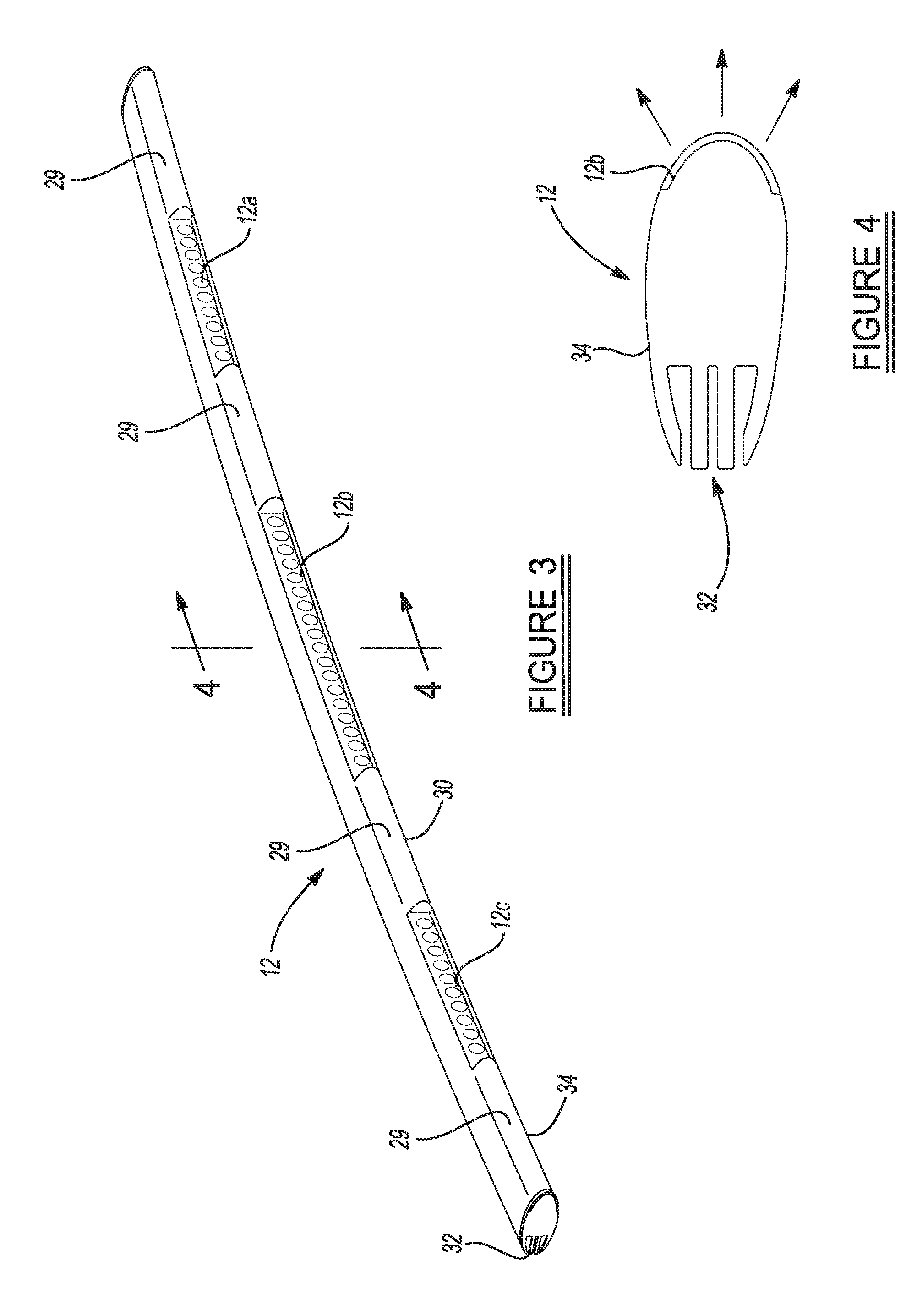
[0015] FIG. 3 is a perspective view of one of the cross bars shown in FIG. 1;
[0016] FIG. 4 is a high level cross sectional view of the cross bar of FIG. 3 taken in accordance with section line 4-4 in FIG. 3;
[0017] FIG. 5 is a high level cross sectional illustration showing another example of a construction for an end support portion for the cross bars of FIG. 1 which enables coupling of the end support of each cross bar to a roof ditch mounted support track while permitting a degree of longitudinal adjustment of the position of each cross bar;
[0018] FIG. 6 is a high level cross sectional illustration of a variation of the end support construction shown in FIG. 5 to illustrate a different shaped support foot and track design that may be used to secure the end supports of the cross bars to their respective ditch rails while permitting a degree of longitudinal positioning of the cross bars;
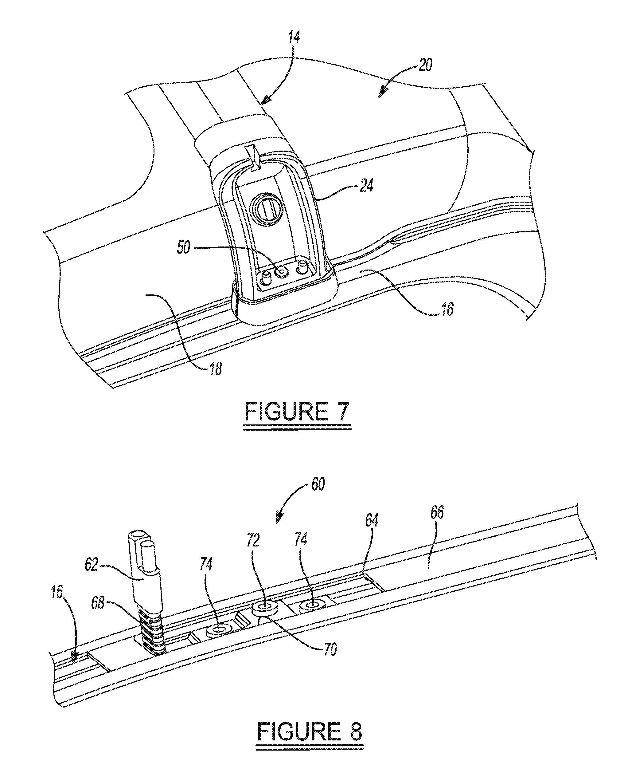
[0019] FIG. 7 is a perspective view showing one of the end supports of FIG. 1 with a fixed or "hard" mounting configuration, wherein the end support is secured to a fixed fastening (not visible in the figure); and
[0020] FIG. 8 is a perspective view of one embodiment of a ditch rail assembly of the present system that makes use of a flip up style electrical connector which can be accessed when needed for attachment to one of the end supports of a cross bar, and which can be positioned within the ditch rail assembly and covered by an external cover (not shown) when not needed for use.
DETAILED DESCRIPTION
[0021] The following description is merely exemplary in nature and is not intended to limit the present disclosure, application, or uses. It should be understood that throughout the drawings, corresponding reference numerals indicate like or corresponding parts and features.
[0022] Referring to FIG. 1 a vehicle article carrier system 10 is shown in accordance with one embodiment of the present disclosure. The system 10 in this example includes a pair of cross bars 12 and 14 that may be secured at different predetermined locations along the ditch rails 16 on a roof 18 of a vehicle 20. The cross bars 12 and 14 include end pairs of supports 22 and 24, respectively, which may be fixedly secured to the ditch rails 16. The cross bars 12 and 14 may be identical in construction but they need not be identical.
[0023] FIG. 2 shows the cross bar 12 having a plurality of lights, e.g., LED lights for example, 12a, 12b and 12c, which face forwardly relative to the vehicle 20 when the cross bar 12 is secured to the ditch rails 16. The cross bar 14 may similarly include a plurality of lights, e.g., LEDs 14a, 14b and 14c, which face rearwardly and thus are not visible in FIG. 1. For convenience, the lights 14a, 14b and 14c have been indicated by dashed lines in FIG. 1. It will be appreciated that the lights 12a-12c and 14a-14c need not be LED style lights, but could be comprised of virtually any other type of light or combinations of two or more different styles of lights (e.g., LED and incandescent). For this example, however, the lights 12a-12c and 14a-14c will be referred to in the following discussion as LED style lights.
[0024] If the cross bars 12 and 14 are identically constructed, then it may be possible to use either cross bar 12 or 14 as a front cross bar, and either one as the rear cross bar. Also, while the lights 12a-12c and 14a-14c have been illustrated as forming a plurality (e.g., three) distinct segments on each cross bar 12 and 14, the cross bars 12 and 14 could be constructed so that the lights 12a-12c and 14a-14c each form a single uninterrupted "light bar" that extends substantially a full length of its associated cross bar 12 or 14.
[0025] Referring to FIG. 2, a portion of the vehicle 20 is shown without the cross bars 12 and 14 secured to the roof 18 to illustrate locations 26 in the ditch rail 16 where the end supports 22 and 24 of the cross bars 12 and 14, respectively, may be secured. At points 26, electrical connectors (not visible) are present which may be connected to mating electrical connectors positioned within the end supports 22 and 24. In this manner electrical power may be provided to the lights 12a-12c and 14a-14c in the cross bars 12 and 14, respectively. While only two such locations 26 are shown in FIG. 2, it will be appreciated that two additional locations are present on the other ditch rail 16 which is not visible in FIG. 2.
[0026] Referring to FIG. 3, cross bar 12 is shown in greater detail. Each of lights 12a-12c in this example may include a plurality of independent LEDs. Virtually any number of LEDs may be used to form each light 12a-12c, although this number will be dependent on design preferences which include the amount of light (e.g., lumens) that each light is to generate, the dimensions (e.g., length and height) of the cross bar 12, and other design variables, the power that is available from the vehicle's electrical system, thermal limitations, physical load management, and additional sensor packaging. The spaces 29 adjacent the lights 12a-12c may be used for attaching nylon straps, bungee cords, etc., and the use of such securing implements does not impede the projection of light from the lights 12a-12c Additional LED lights could be disposed along a lower surface 30 of the cross bar 12 just as well for accent lighting. In this example, the lights 12a-12c form an off-road lighting system that is sufficiently powerful to project a useful light beam when operating the vehicle 20 off-road.
[0027] FIG. 4 shows a cross sectional view of the cross bar 12 illustrating integrally formed cooling fins 32 on the cross bar 12. The integrally formed cooling fins 32 may be formed simultaneously with the forming of a metallic housing portion 34 of the cross bar 12 during a manufacturing process, for example an extrusion molding process. The housing portion 34 may be made from aluminum or any other materials that are thermally conductive. The cooling fins 32 in this example are integrally formed cooling fins which remove the issue of how to manage heat buildup within the cross bar 12 without providing holes for air circulation. Obviously, the use of holes is undesirable as water and other elements could potentially enter the interior of the cross bar 12. The addition of holes may also generate wind noise during vehicle operation. Still further, while the cooling fins 32 are described in the following description as being integrally formed with the cross bar 12, the cooling fins 32 could be formed by an independent component or independent assembly of components that are affixed to the cross bar 12. Both implementations are envisioned by the present disclosure.
[0028] The use of cooling fins 32 on the cross bar 12 also forms a highly cost effective, easy to manufacture solution that does not otherwise require a redesign of the entire cross bar 12. Still further, the lights 12a-12c and the cooling fins 32 do not detract tangibly from the overall structural strength of the cross bar 12, which enables the cross bar to be used for its main purpose: supporting loads thereon. Another advantage is that the integrally formed cooling fins 32 do not detract appreciably from the aerodynamic shape and aesthetically pleasing profile of the cross bar 12. In FIG. 4 it can be seen that the integrally formed cooling fins 32 generally follow the cross sectional profile of the cross bar 12, and thus do not require increasing the cross sectional footprint of the cross bar 12.
[0029] FIGS. 5 and 6 show variations of the construction of the end support 22 that allows the end support to be adjustably positioned on a track 40 (FIG. 5) mounted in the ditch rail 16. In FIG. 5 an end support 22' is shaped with a foot portion 42 that mounts within the track 40. The track 40 in this example forms an upwardly facing C-shaped track. FIG. 6 shows another example of an end support 22'' having a wedge shaped foot portion 44 that engages on a complementary shaped track 46. Thus, in both instances the end support 22' or 22'' is free to slide along its respective track (40 or 46). The end supports 22' and 22'' in this example will preferably have a locking mechanism that secures them at a desired point along the track.
[0030] FIG. 7 shows the end support 24 of the cross bar 12 with a cover element removed to expose a mounting fastener 50 to achieve a "hard" mounting to the ditch rail 16. In this example the ditch rail 16 may include an opening (not visible) where a threaded fastening element (not shown) may be mounted. Thus, the cross bar 14 in this example will be fixedly secured at both of its end supports 24 at a desired location along the ditch rails 16. Once secured, the cover element may be re-secured to each end support 24 to provide an aesthetically pleasing appearance.
[0031] FIG. 8 illustrates a ditch rail assembly 60 having a flip up power source connection 62 accessible through an opening 64 in a cover element 66 that covers the ditch rail 16. The flip up power source connection 62 may have a flexible insulating sheath 68 that enables the power source connection 62 to be laid down generally parallel to the ditch rail 16 when the cross bar 12 or 14 is detached from the vehicle roof 18, and covered using an external cover element (not shown). When the cross bar 12 or 14 is to be attached, the power source connection 62 can be lifted up and connected to a mating electrical connector in the end support (22 or 24) before the end support is fixedly secured to a mounting element 70 of the ditch rail assembly 60. The mounting element 70 includes a center threaded female fastener 72 which can be used to receive a threaded male fastener, such as the mounting fastening 50 in FIG. 7, to secure the end support (22 or 24) to the ditch rail assembly 60. Fasteners 74 in this example secure the mounting element 70 to the vehicle roof 18.
[0032] While various embodiments have been described, those skilled in the art will recognize modifications or variations which might be made without departing from the present disclosure. The examples illustrate the various embodiments and are not intended to limit the present disclosure. Therefore, the description and claims should be interpreted liberally with only such limitation as is necessary in view of the pertinent prior art.
* * * * *
D00000
D00001
D00002
D00003
D00004
XML
uspto.report is an independent third-party trademark research tool that is not affiliated, endorsed, or sponsored by the United States Patent and Trademark Office (USPTO) or any other governmental organization. The information provided by uspto.report is based on publicly available data at the time of writing and is intended for informational purposes only.
While we strive to provide accurate and up-to-date information, we do not guarantee the accuracy, completeness, reliability, or suitability of the information displayed on this site. The use of this site is at your own risk. Any reliance you place on such information is therefore strictly at your own risk.
All official trademark data, including owner information, should be verified by visiting the official USPTO website at www.uspto.gov. This site is not intended to replace professional legal advice and should not be used as a substitute for consulting with a legal professional who is knowledgeable about trademark law.