Method For Calibrating At Least One Scanning System Of An Sls Or Slm Installation
HERZOG; Frank ; et al.
U.S. patent application number 16/083840 was filed with the patent office on 2019-05-09 for method for calibrating at least one scanning system of an sls or slm installation. This patent application is currently assigned to CONCEPT LASER GMBH. The applicant listed for this patent is CL Schutzrechtsverwaltungs GmbH. Invention is credited to Florian BECHMANN, Frank HERZOG, Fabian ZEULNER.
| Application Number | 20190134747 16/083840 |
| Document ID | / |
| Family ID | 57995185 |
| Filed Date | 2019-05-09 |


| United States Patent Application | 20190134747 |
| Kind Code | A1 |
| HERZOG; Frank ; et al. | May 9, 2019 |
METHOD FOR CALIBRATING AT LEAST ONE SCANNING SYSTEM OF AN SLS OR SLM INSTALLATION
Abstract
The invention concerns a method for calibration of at least one scanning system of a laser sintering or laser melt facility with the further characteristics of the preamble of Claim 1.
| Inventors: | HERZOG; Frank; (Lichtenfels, DE) ; BECHMANN; Florian; (Lichtenfels, DE) ; ZEULNER; Fabian; (Lichtenfels, DE) | ||||||||||
| Applicant: |
|
||||||||||
|---|---|---|---|---|---|---|---|---|---|---|---|
| Assignee: | CONCEPT LASER GMBH Lichtenfels DE |
||||||||||
| Family ID: | 57995185 | ||||||||||
| Appl. No.: | 16/083840 | ||||||||||
| Filed: | February 2, 2017 | ||||||||||
| PCT Filed: | February 2, 2017 | ||||||||||
| PCT NO: | PCT/EP2017/052273 | ||||||||||
| 371 Date: | September 10, 2018 |
| Current U.S. Class: | 1/1 |
| Current CPC Class: | G05B 19/401 20130101; B33Y 50/02 20141201; B29C 64/153 20170801; B33Y 10/00 20141201; B23K 26/34 20130101; B33Y 50/00 20141201; B22F 2003/1057 20130101; B23K 26/354 20151001; B22F 3/1055 20130101; G05B 2219/49018 20130101; B29C 64/386 20170801; B29C 64/393 20170801; G05B 2219/37017 20130101 |
| International Class: | B23K 26/34 20060101 B23K026/34; B22F 3/105 20060101 B22F003/105; B33Y 10/00 20060101 B33Y010/00; B33Y 50/00 20060101 B33Y050/00; B23K 26/354 20060101 B23K026/354 |
Foreign Application Data
| Date | Code | Application Number |
|---|---|---|
| Apr 7, 2016 | DE | 10 2016 106 403.3 |
Claims
1. A procedure for calibration of at least one scanning system (6a/6b) of a laser sinter (SLS) or laser melt (SLM) facility (1) in which by means of the at least one scanning system (6a/6b) the pencil beam (4) of at least one beam source, in particular of a laser (3), is directed onto a construction field (2) in order by means of a construction process to melt or fuse a construction material capable of sintering or melting and thus through its cooling selectively to solidify characterized by the following calibration and procedural steps: Generation of at least one line pattern, particularly of a scanning grid (8a/8b), through the at least one scanning system (6a/6b) on a surface at the level of the construction field (2), whereby the line pattern is projected either on a surface element showing the line pattern temporarily or constantly, whose image during the generation of the line pattern(s) is read or subsequently recorded by a calibrated camera (9) configured over the construction field (2) and read into a memory (7), or the line pattern(s) is (are) projected on the upper surface of the calibration plate already provided with an applied specified line pattern and the deviation of the line pattern produced by at least one scanning system (6a/6b) from the specified line pattern is recorded by a camera (9) configured over the construction field (2) and read into a memory (7); execution of a field correction of the line pattern by calculation of correction data regarding in essence the one scanning system (6a/6b) which data contain the necessary information for correction of any distortions of the line pattern, especially of the scanning grid (8a/8b) and subsequent correction of the line pattern for avoidance of imaging errors.
2. A procedure according to claim 1, the characterized in that after correction of the distortion of the line pattern with a number of scanning systems (6a/6b) over one and the same construction field (2), illumination by means of a calibrated camera (9) over the construction field (9), reading in the position line patterns, in particular the position grids (8c, 8d) of the respective number of scanning systems (6a/6b), which are already corrected as regards any distortions, is done. a calculation of further correction data regarding rotation, offset, scaling, and/or displacement regarding the systems (6a/6b) to each other in such a way that by use of further correction data on several scanning systems (6a/6b) and mutual alignment and accommodation of several scanning systems (6a/6b) and the position grid (8c/8d) produced by them is achieved.
3. A procedure according to claim 1 characterized in that calculation of further correction data for every separate scanning system (6a/6b) is done.
4. A procedure according to claim 3 characterized in that calculation data determined for every scanning system (6a/6b) is aggregated into a combined correction data set covering all systems (6a/6b).
5. A procedure according to claim 2 characterized in that calculation of further correction data is done for the outer limits of the construction field (2).
6. A procedure according to claim 2 characterized in that the position line pattern (8c/8d) intersects the scanning systems (6a/6b) configured next to each other area by area.
7. A procedure according to claim 2 characterized in that the position line patterns (8c/8d) of adjacent scanning systems (6a/6b) are configured separately next to each other.
8. A procedure according to claim 2 characterized in that the deviation from adjacent position line patterns (8c/8d) or the position line patterns (8c/8d) that overlap in areas due to mutual rotation, mutual offset, mutual scaling, or numerical displacement is shown on a display (15).
9. A procedure according to claim 1 characterized in that the surface unit is illuminated so that a laser beam (4) of a scanning system (6a/6b) produces a constantly visible line pattern or position line pattern (8c/8d) detectable by a camera (9) over the construction field (2).
10. A procedure according to claim 1 characterized in that with use of a calibration plate the deviation of a detectable line pattern temporarily visible on the surface of the calibration plate and recordable with the camera (9) over the construction field (2) is measured and corrected so that the line pattern produced by the scanning system (6a/6b) coincides with the specified line pattern.
11. A procedure according to claim 1 characterized in that with provision of a scanning system (6a/6b) the ascertained correction values concerning rotation, scaling, and displacement relate to the position of the line pattern in the construction chamber or related to the edges of the construction chamber.
Description
[0001] The invention concerns a method for calibration of at least one scanning system of a laser sintering or laser melt facility with the further characteristics of the preamble of Claim 1.
[0002] Laser sinter or laser melt systems are provided to manufacture three-dimensional objects by means of a rapid manufacturing process especially through solidification of powdered construction material. In the process, the beam of a light source, usually a laser, is directed by a scanning system onto a construction surface on which there is a thin layer of the construction material. The focused laser beam is suitable for melting and fusing the construction material. The construction material solidifies after the formed melt pool or melt site cools in this location and forms the three-dimensional object by successive adhesion and selective solidification of further layers.
[0003] It is of highest importance for the precision and reproducibility of the construction process that the scanning system(s) of a such laser sinter or laser melt facility exactly reproduce what is stored in a construction program that guides the construction process, in other words the alignment of the laser beam in the area of the construction field level does not deviate from a stored specified line that is mapped by the scanning system(s).
[0004] It is recognized as the state of the art that the scanner must be exactly aligned manually and this manual alignment then technically checked by software. This is time-consuming, so such an adjustment of the scanning systems is usually done at most only once or twice annually. Besides the high expenditure of time for a manual adjustment, it is also subject to error.
[0005] The object of the invention is to form a procedure for calibration of at least one scanning system of a laser sinter or laser melt facility so that the procedure can be carried out in a short time, can take place automatically, and thereby can be carried out before each individual construction process. The object is fulfilled through the characteristic features of claim 1. Advantageous further development, especially also in regard to several scanning systems, can be seen from the dependent claims. In detail, the process provides the following steps for carrying out calibration.
[0006] A line pattern, particularly a line grid in the form of a scanning grid, is first produced through at least one scanning system on a surface at the level of the construction field. There are two alternatives here: The first alternative is to project onto a surface unit indicating the line pattern, whereby the display on the surface unit is either temporarily or constantly visible. A temporary display like a constant display of the line pattern can also be recorded by a calibrated cell configured over the construction field and read into a memory.
[0007] It is alternately in the scope of the invention to project the line pattern produced by the scanner onto the surface of a calibration plate that already has a specified line pattern on its surface. The deviation of the line pattern produced from the specified line pattern by at least one scanning system can be captured by a camera configured over the construction field and also be read into a memory. The stored data are analyzed according to the first alternative or the deviating data according to the second alternative. A field correction of the line pattern is made by calculation of the correction data that contain the required information for correction of any distortion of the line pattern, especially of the scan grid. In particular, especially pillow-shaped, barrel-shaped, rhomboid, or square-shaped distortions of a, for example, quadratic or other target sample are affected. Correction is in every respective conceivable.
[0008] Up to now, the depicted process was based on the calibration of only one scanner, whereby naturally two scanners respectively for themselves and in a given case independently of each other can be corrected in the way described. It is possible now in further development of the procedure after correction of any distortions of the line pattern by means of a number of scanning systems to undertake illumination over one and the same construction field and thereby produce position line patterns and then an adjustment of these position line patterns, especially position grids of the given number of scanning systems to each other, which, as regards any distortions, are already corrected internally in the scanning systems. A calculation is then made of further correction data regarding possible required rotation, offset, scaling, and/or displacement of the systems with each other. By use of further correction data on several scanning systems a mutual alignment and accommodation of several scanning systems is achieved. In this way, for example, the line patterns of several scanning systems can be brought exactly into overlap position or lying exactly beside each other.
[0009] If the calculation of the further correction data is separate for every scanning system, then every scanning system can individually be accessed by means of correction data so that adjacent scanning systems or a boundary of the construction field can be precisely aligned. It is, however, also possible to consolidate the correction data ascertained for each scanning system into a total correction data set. Use of this total correction data set for all scanning systems consequently leads to an exact alignment of the various scanning systems with each other. Calculation of further correction data can also be carried out separately related to the outer boundaries of the construction field, so that, for example, the edges of the position line patterns are made parallel with the edges of the construction field.
[0010] As already noted, the position line patterns can partially overlap the scanning systems configured next to each other. Mutual correction and alignment can be carried out in that, for example, the edge lines of position line patterns produced by different scanning systems can be positioned congruently over each other or at least partially congruently.
[0011] It is also basically in the scope of the invention to indicate deviation data of position line patterns next to or intersecting each other in areas as regards mutual rotation, mutual offsets, and similar parameters numerically on a display of laser sinter or laser melt equipment. "Angular deviation 3.degree." can, for example, be indicated. A display of this kind gives the user of the facility information that a correction is not yet finished and a manual or partly automated correction is required in order actually to be able to coordinate side-by-side scanning systems so that they produce the same image on the construction field.
[0012] The surface unit that is illuminated with a laser beam can be layered. The coating can be configured so that a constantly visible image is burned into the coating by the laser beam.
[0013] It is also possible in further development of the invention to integrate the calibration procedure as a subprogram in a construction program for a three-dimensional object and let this subprogram run from the beginning of a construction job so that at the beginning of the actual construction job it is automatically assured that the scanners of the facility carrying out the construction job are coordinated with each other.
[0014] The invention is explained in more detail in the exemplary embodiments in the drawings. The following are shown:
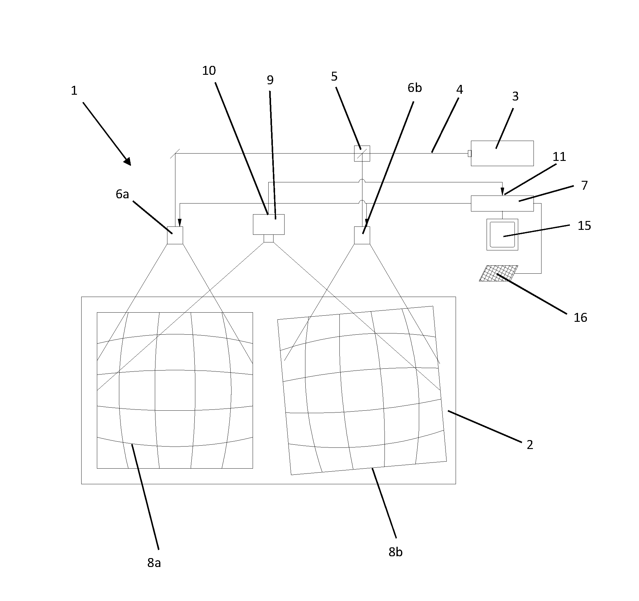
[0015] FIG. 1 a greatly simplified schematic depiction of a construction field of a laser sinter or laser melt facility with scanners mounted above it along with a calibrated camera for carrying out calibration of a scanner from line patterns produced by a scanner;
[0016] FIG. 2 a depiction according to FIG. 1, in which a pillow-shaped distortion according to FIG. 1 has already been corrected for each individual scanner;
[0017] FIG. 3 a depiction according to FIGS. 1 and 2, in which mutual alignment and calibration of the scanners is undertaken for parallel alignment of the position line patterns;
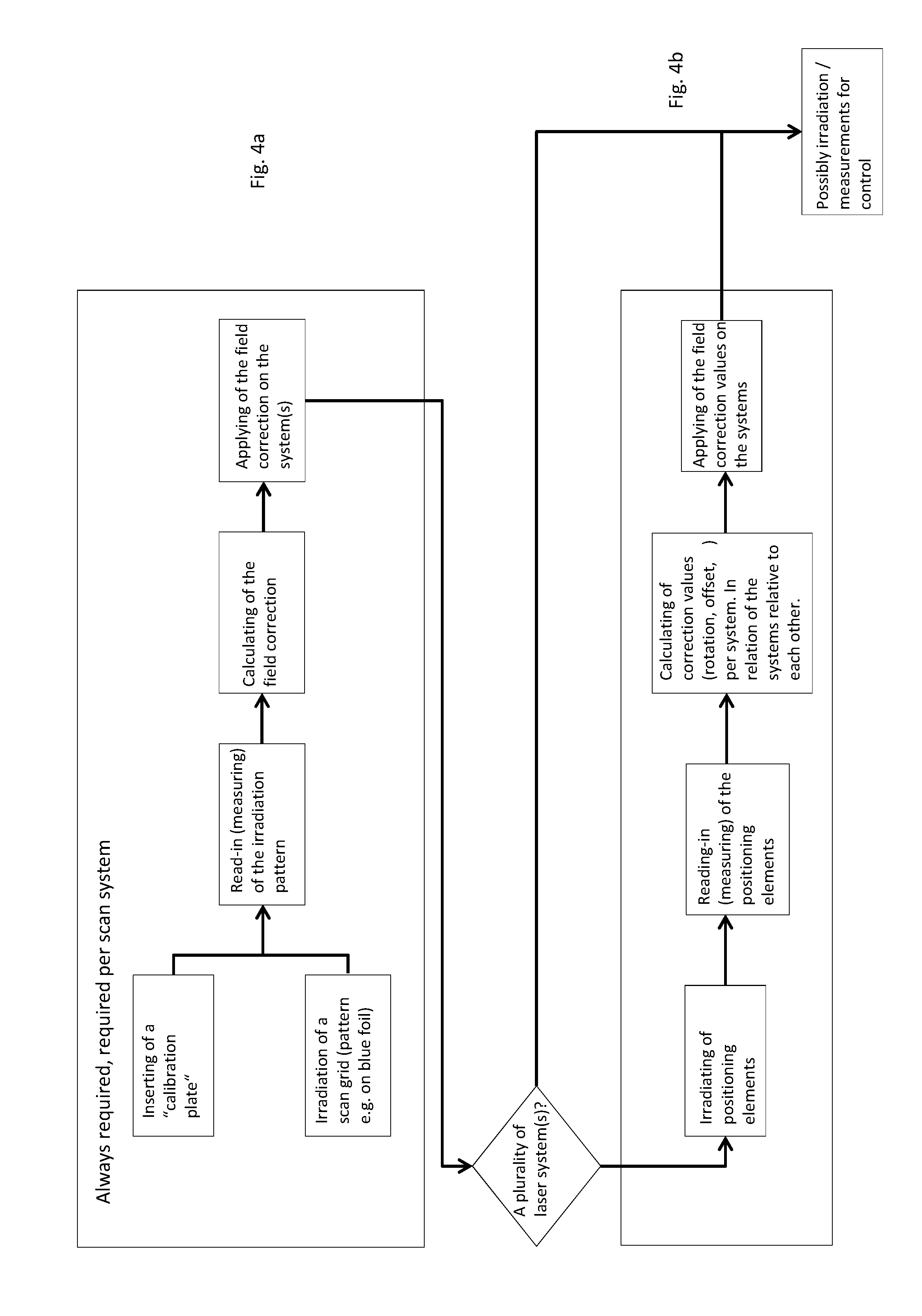
[0018] FIG. 4 a simplified schematic flow diagram of the procedures running with the calibration.
[0019] Reference will first be made to drawing FIGS. 1-3. For reasons of simplification, in only the elements of a laser sinter or laser melt facility essential for the invention that can be scanned are depicted in drawing FIG. 1, namely a construction field 2 that can be scanned by radiation from a laser 3 is shown in drawing FIG. 1. Beam 4 of the laser is, in addition, fed via a beam splitter 5 to two scanners 6a and 6b that direct the beam source of the laser onto the construction field 2 via a mirror controlled by a processor and memory 7 and produce the scanning grids 8a and 8b with a pillow-shaped distortion shown in FIG. 1. These scanning grids are scanned by a calibrated camera 9. The output 10 of the camera 9 is connected with an input 11 of processor 7, whereby the recorded line patterns 8a and 8b can be read into the memory of processor 7. Field correction is calculated in processor 7 implemented by calculation of correction data for each scanning system 6a and 6b, whereby the correction data contain information for the correction of any distortions of the line pattern 8a/8b. These correction data are associated with appurtenant target data in processor 7, so that correction of the line patterns 8a, 8b results as depicted in FIG. 2. As a result, the pillow-shaped distortions are rectified in both line patterns 8a and 8b produced by the scanners 6a and 6b. The path of the laser focus produced by the mirrors of the scanners exactly follows the parameters of the stored pattern that in the exemplary case is a chess-board pattern. Admittedly, it is still evident in FIG. 2 that the line pattern 8b of the scanner 6b is tilted by some degrees to the line pattern 8a of the scanner 6a. In the case that there are several scanners configured over one and the same construction field, a mutual alignment of the line patterns is necessary. These line patterns, in the following designated as position line patterns 8c, 8d, are read in by the camera, whereby already read-in data on line patterns can be referred to, which already have been entered into memory 7, in order to correct the pillow-shaped distortions in the first step of correction. From this now available data, further correction data are [missing infinitive] regarding mutual rotation, offset, scaling and/or displacement of the systems to each other in that by use of further correction data on several scanning systems a mutual alignment and accommodation of several scanning systems to each other is achieved. This is done exclusively by software according to the invention, whereby basic mechanical orientation of the scanners to each other is extremely useful and can, for example, be carried out in initial startup of a device. The result of this use of further correction data is evident in FIG. 3. Now the line patterns or position line patterns 8c, 8d are exactly aligned next to each other and can also be configured to be overlapping, i.e. the scanner 6b can also exactly track construction field areas that are configured in the position line pattern area 8a.
[0020] It is basically conceivable to display the correction data or measured distortions, angles, and similar on a display 15 of the device 1 and in a given case to intervene in the correction procedure by means of an input device in the form of a keyboard 16.
[0021] The flow diagram according to FIG. 4 is divided into two section FIGS. 4a and 4b. According to section FIG. 4a either a line grid can be radiated or a calibration plate can be inserted. The read-in or measuring of the radiation pattern and a calculation of the field correction is then carried out, whereby the field correction data are used for the system(s) for remediation of, for example, pillow-shaped distortions, as can be seen in the transition from FIG. 1 to FIG. 2.
[0022] If several laser systems are provided, as in the schematic depiction according to FIGS. 1-3, the line patterns, now termed position line patterns, are exposed and measured through the camera 9 and then correction data regarding rotation calculates an offset-pro-system in reference to the systems. The use of these further correction values on the systems leads to a mutually exact alignment of the line patterns with each other, as can be seen in the transition from FIG. 2 to FIG. 3.
REFERENCE NUMBER LIST
[0023] 1 Laser sinter or laser melt facility/operation [0024] 2 Construction field [0025] 3 Laser [0026] 4 Beam [0027] 5 Beam splitter [0028] 6a/b Scanning grid, scanning system [0029] 7 Processor and memory [0030] 8a/b Scanning grid [0031] 8c/d Position line pattern [0032] 9 Calibrated camera [0033] 10 Exit [0034] 11 Entrance [0035] 15 Display [0036] 16 Keyboard
* * * * *
D00000
D00001
D00002
D00003
D00004
XML
uspto.report is an independent third-party trademark research tool that is not affiliated, endorsed, or sponsored by the United States Patent and Trademark Office (USPTO) or any other governmental organization. The information provided by uspto.report is based on publicly available data at the time of writing and is intended for informational purposes only.
While we strive to provide accurate and up-to-date information, we do not guarantee the accuracy, completeness, reliability, or suitability of the information displayed on this site. The use of this site is at your own risk. Any reliance you place on such information is therefore strictly at your own risk.
All official trademark data, including owner information, should be verified by visiting the official USPTO website at www.uspto.gov. This site is not intended to replace professional legal advice and should not be used as a substitute for consulting with a legal professional who is knowledgeable about trademark law.