Spinning Top Toy
MURAKI; Makoto ; et al.
U.S. patent application number 16/017201 was filed with the patent office on 2019-05-09 for spinning top toy. This patent application is currently assigned to TOMY Company, Ltd.. The applicant listed for this patent is TOMY Company, Ltd.. Invention is credited to Takeaki MAEDA, Makoto MURAKI.
| Application Number | 20190134517 16/017201 |
| Document ID | / |
| Family ID | 62846062 |
| Filed Date | 2019-05-09 |


| United States Patent Application | 20190134517 |
| Kind Code | A1 |
| MURAKI; Makoto ; et al. | May 9, 2019 |
SPINNING TOP TOY
Abstract
A spinning top toy for being rotated around a rotating axis includes a shaft part being configured to be in contact to a floor, and a body being detachably attached to the shaft part. One of the shaft part and the body includes first and second divided pieces including first and second coupling parts respectively. The first coupling part is configured to be coupled detachably with the second coupling part. The first and second divided pieces are arranged on a plane perpendicular to the rotating axis when the first and second coupling parts are coupled.
| Inventors: | MURAKI; Makoto; (Tokyo, JP) ; MAEDA; Takeaki; (Tokyo, JP) | ||||||||||
| Applicant: |
|
||||||||||
|---|---|---|---|---|---|---|---|---|---|---|---|
| Assignee: | TOMY Company, Ltd. Tokyo JP |
||||||||||
| Family ID: | 62846062 | ||||||||||
| Appl. No.: | 16/017201 | ||||||||||
| Filed: | June 25, 2018 |
| Current U.S. Class: | 1/1 |
| Current CPC Class: | A63H 1/04 20130101; A63F 9/16 20130101 |
| International Class: | A63H 1/02 20060101 A63H001/02 |
Foreign Application Data
| Date | Code | Application Number |
|---|---|---|
| Jul 7, 2017 | JP | 2017-133679 |
Claims
1. A spinning top toy for being rotated around a rotating axis, comprising: a shaft part being configured to be in contact to a floor; and a body being detachably attached to the shaft part; one of the shaft part and the body including first and second divided pieces including first and second coupling parts respectively, the first coupling part being configured to be coupled detachably with the second coupling part, the first and second divided pieces being arranged on a plane perpendicular to the rotating axis when the first and second coupling parts are coupled.
2. The spinning top toy according to claim 1, wherein the first and second divided pieces form a circumference of the body which is outermost from the rotation axis.
3. The spinning top toy according to claim 2, wherein the body includes an overhanging part which protrudes outwardly in a radial direction.
4. The spinning top toy according to claim 1, wherein the first coupling part includes a convex part, and the second coupling part includes a concave part.
5. The spinning top toy according to claim 4, wherein each of the first and second divided pieces is semicircular, and the first and second coupling parts are engaged by moving in an opposite direction to each other in a diameter direction.
6. The spinning top toy according to claim 5, further comprising a stopper, wherein the body has a hole at a center on a top surface thereof, and the stopper is configured in the hole to secure the first and second divided pieces.
7. The spinning top toy according to claim 1, wherein the spinning top toy is for battling against an opponent top toy by colliding the body to the opponent top toy, and a characteristic of the spinning top toy is changed by replacing the first divided piece.
8. The spinning top toy according to claim 1, further comprising a third divided piece, wherein the first divided piece is replaceable with the third divided piece.
9. The spinning top toy according to claim 8, wherein the first divided piece has a first shape, and the third divided piece has a third shape being different from the first shape.
10. The spinning top toy according to claim 9, wherein the first divided piece is made of a first material, and the third divided piece is made of a third material being different from the first material.
Description
CROSS-REFERENCE TO RELATED APPLICATIONS
[0001] The present application claims priority under 35 U.S.C. 119 to Japanese Patent Application No. 2017-133679, filed on Jul. 7, 2017. The contents of this application are incorporated herein by reference in their entirety.
BACKGROUND OF THE INVENTION
Field of the Invention
[0002] The present invention relates to a spinning top toy.
Description of the Related Art
[0003] As battle games using spinning top toys, by applying impact to the spinning top toys each other, there are cases in which the rotation of the spinning top toy of an opponent is stopped by the impact force, the spinning top toy of the opponent is flicked out by the impact force, or the spinning top toy of the opponent is disassembled by the impact force, etc.
[0004] In such spinning top toys for battle games, a part colliding with the opponent, that is, a blade shaped overhanging part is formed on a circumference surface of a body, so that the overhanging part is collided.
[0005] As this kind of spinning top toys, it is well-known that a body is configured with a plurality of body pieces (divided pieces) laminated in a vertical direction (up and down direction)(see e.g., Japanese Utility Model Registered Publication No. 3079269). According to this kind of spinning top toys, alternative body pieces in which exterior shapes, weights, or materials are different are prepared in advance, and the characteristics of the spinning top toys can change by replacing a body piece in every body piece unit.
[0006] Generally, a spinning top toy collides with an opponent by contacting an outermost periphery uneven part. Therefore, when viewing an exterior shape of a body, the characteristics of the spinning top toy largely rely on the shape of the outermost periphery uneven part of the body.
[0007] Therefore, when the characteristics of the spinning top toy try to change by changing the shape of the outermost periphery uneven part of the body, in the case of the aforementioned spinning top toy, it is required to change the exterior shape of the body pieces which form the outermost periphery uneven part of the body.
[0008] However, in the case of the aforementioned spinning top toy, since the body is made up with the body pieces in the laminated structure, each body piece must be thin and fragile in comparison with the body in an integral structure. Therefore, in the case of the aforementioned spinning top toy, in order to make sufficiently durable structure for colliding with the opponent, it is required to laminate a plurality of body pieces, which include the outermost periphery uneven part of the body, and which have almost the same exterior shapes. However, it is troublesome to prepare the plurality of body pieces having almost the same exterior shapes in advance.
[0009] Further, the characteristics of the spinning top toys rely on a weight or a material of the body. It is because when the weight or the material changes, the impact force applying to the opponent or receiving own spinning top toy changes or the rotation characteristics change.
[0010] However, in the case of the aforementioned spinning top toys, each body piece itself is made of a uniform material, and the shape with a balance in a circumferential direction is formed. Therefore, for example, even if a body piece with different weight is replaced, the center of gravity changes only in the vertical direction. In addition, even if a body piece with different material is replaced, the characteristics become uniform in the circumferential direction. That is, regardless of whether any portion of the spinning top toy in the circumferential direction collides with, the shock-absorbing effect becomes uniform.
[0011] In view of the design, specifically, the top surface of the body is the portion which players easily see, but in the case of the aforementioned spinning top toys, the changeful design cannot be enjoyed unless the most upper body pieces are replaced.
[0012] The description herein of advantages and disadvantages of various features, embodiments, methods, and apparatus disclosed in other publications is in no way intended to limit the present invention. For example, certain features of the preferred described embodiments of the invention may be capable of overcoming certain disadvantages and/or providing certain advantages, such as, e.g., disadvantages and/or advantages discussed herein, while retaining some or all of the features, embodiments, methods, and apparatus disclosed therein.
SUMMARY OF THE INVENTION
[0013] The disclosed embodiments of the present invention have been developed in view of the above-mentioned and/or other problems in the related art. The disclosed embodiments of the present invention can significantly improve upon existing methods and/or apparatuses.
[0014] The present invention was created considering the aforementioned problems. An object is to provide a spinning top toy which easily perform rearrangement and can enjoy changes in configuration in a horizontal direction.
[0015] In some embodiments of the present disclosure, a spinning top toy for being rotated around a rotating axis includes a shaft part being configured to be in contact to a floor, and a body being detachably attached to the shaft part. One of the shaft part and the body includes first and second divided pieces including first and second coupling parts respectively. The first coupling part is configured to be coupled detachably with the second coupling part. The first and second divided pieces are arranged on a plane perpendicular to the rotating axis when the first and second coupling parts are coupled.
[0016] In some embodiments of the present disclosure, the first and second divided pieces form a circumference of the body which is outermost from the rotation axis.
[0017] In some embodiments of the present disclosure, the body includes an overhanging part which protrudes outwardly in a radial direction.
[0018] In some embodiments of the present disclosure, the first coupling part includes a convex part, and the second coupling part includes a concave part.
[0019] In some embodiments of the present disclosure, each of the first and second divided pieces is semicircular, and the first and second coupling parts are engaged by moving in an opposite direction to each other in a diameter direction.
[0020] In some embodiments of the present disclosure, the spinning top toy further includes a stopper. The body has a hole at a center on a top surface thereof, and the stopper is configured in the hole to secure the first and second divided pieces.
[0021] In some embodiments of the present disclosure, the spinning top toy is for battling against an opponent top toy by colliding the body to the opponent top toy, and a characteristic of the spinning top toy is changed by replacing the first divided piece.
[0022] In some embodiments of the present disclosure, the spinning top toy further includes a third divided piece, wherein the first divided piece is replaceable with the third divided piece.
[0023] In some embodiments of the present disclosure, the first divided piece has a first shape, and the third divided piece has a third shape being different from the first shape.
[0024] In some embodiments of the present disclosure, the first divided piece is made of a first material, and the third divided piece is made of a third material being different from the first material.
[0025] The above and/or other aspects, features and/or advantages of various embodiments will be further appreciated in view of the following description in conjunction with the accompanying figures. Various embodiments can include and/or exclude different aspects, features and/or advantages where applicable. In addition, various embodiments can combine one or more aspect or feature of other embodiments where applicable. The descriptions of aspects, features and/or advantages of particular embodiments should not be construed as limiting other embodiments or the claims. In the drawings, the size and relative sizes of layers and regions may be exaggerated for clarity. Like numbers refer to like elements throughout. The terminology used herein is for the purpose of describing particular embodiments only and is not intended to be limiting of the invention. As used herein, the singular forms "a", "an" and "the" are intended to include the plural forms as well, unless the context clearly indicates otherwise. As used herein, the term "and/or" includes any and all combinations of one or more of the associated listed items and may be abbreviated as "/". It will be understood that, although the terms first, second, etc. may be used herein to describe various elements, these elements should not be limited by these terms. Unless indicated otherwise, these terms are only used to distinguish one element from another. For example, a first object could be termed a second object, and, similarly, a second object could be termed a first object without departing from the teachings of the disclosure. It will be further understood that the terms "comprises" and/or "comprising," or "includes" and/or "including" when used in this specification, specify the presence of stated features, regions, integers, steps, operations, elements, and/or components, but do not preclude the presence or addition of one or more other features, regions, integers, steps, operations, elements, components, and/or groups thereof. It will be understood that when an element is referred to as being "connected" or "coupled" to or "on" another element, it can be directly connected or coupled to or on the other element or intervening elements may be present. In contrast, when an element is referred to as being "directly connected" or "directly coupled" to another element, there are no intervening elements present. Other words used to describe the relationship between elements should be interpreted in a like fashion (e.g., "between" versus "directly between," "adjacent" versus "directly adjacent," etc.). However, the term "contact," as used herein refers to direct contact (i.e., touching) unless the context indicates otherwise. Terms such as "same," "planar," or "coplanar," as used herein when referring to orientation, layout, location, shapes, sizes, amounts, or other measures do not necessarily mean an exactly identical orientation, layout, location, shape, size, amount, or other measure, but are intended to encompass nearly identical orientation, layout, location, shapes, sizes, amounts, or other measures within acceptable variations that may occur, for example, due to manufacturing processes. The term "substantially" may be used herein to reflect this meaning. Unless otherwise defined, all terms (including technical and scientific terms) used herein have the same meaning as commonly understood by one of ordinary skill in the art to which this disclosure belongs. It will be further understood that terms, such as those defined in commonly used dictionaries, should be interpreted as having a meaning that is consistent with their meaning in the context of the relevant art and/or the present application, and will not be interpreted in an idealized or overly formal sense unless expressly so defined herein.
BRIEF DESCRIPTION OF THE DRAWINGS
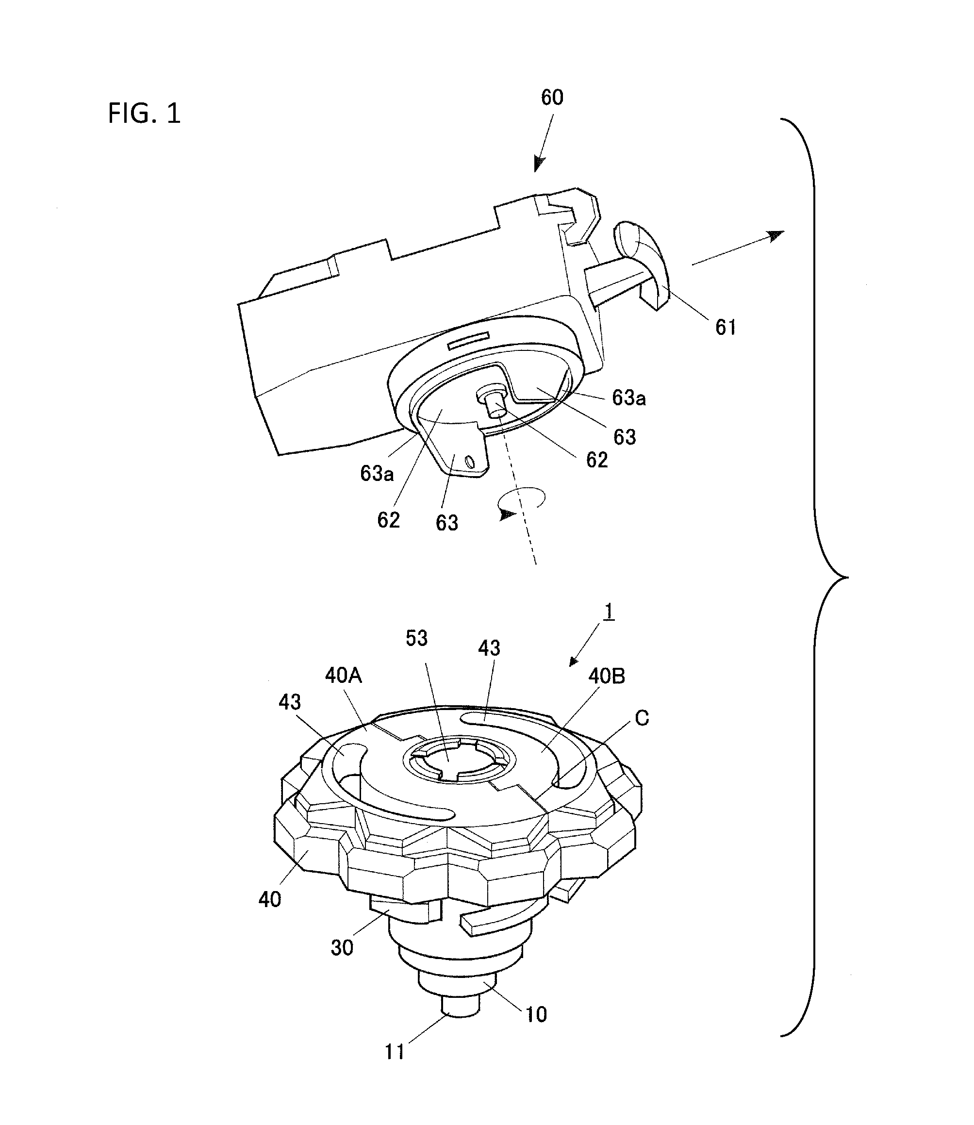
[0026] FIG. 1 is a perspective view showing a spinning top toy and a launcher (spinning top toy launcher) according to an embodiment.
[0027] FIG. 2 is a perspective view explaining how to play with a spinning top toy according to the present embodiment.
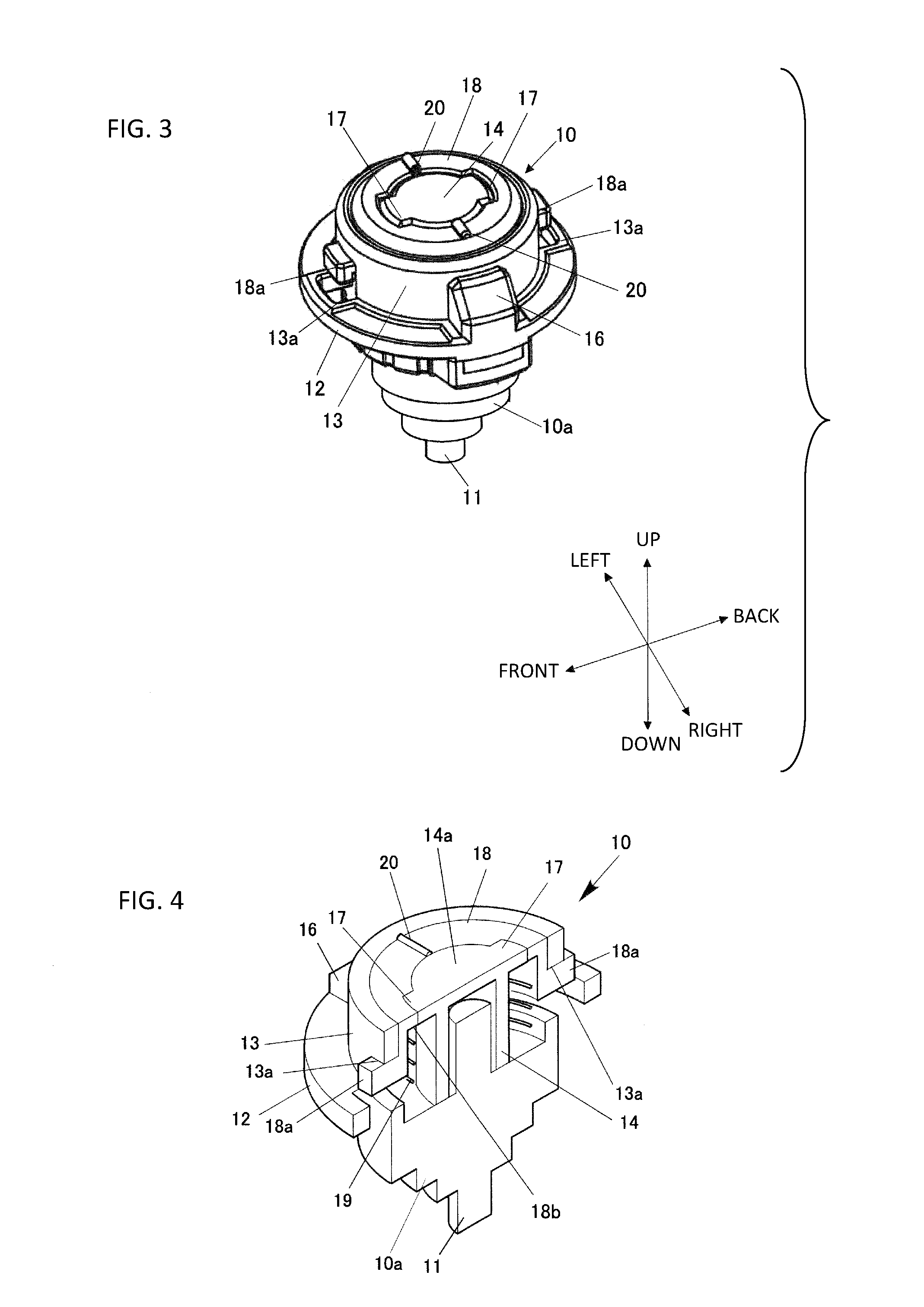
[0028] FIG. 3 is a perspective view showing a shaft part of the spinning top toy according to the present embodiment.
[0029] FIG. 4 is a cross-sectional perspective view showing a shaft part of the spinning top toy according to the present embodiment.
[0030] FIG. 5 is a perspective view showing a state in which a flywheel of the spinning top toy according to the present embodiment is viewed from the upper side.
[0031] FIG. 6 is a perspective view showing a state in which the flywheel of the spinning top toy according to the present embodiment is viewed from the lower side.
[0032] FIG. 7 is a perspective view showing a state in which a body of the spinning top toy according to the present embodiment is viewed from the upper side.
[0033] FIG. 8 is a perspective view showing a state in which the body of the spinning top toy according to the present embodiment is viewed from the lower side.
[0034] FIG. 9 is an exploded perspective view of the body of the present embodiment showing a coupling means.
[0035] FIG. 10 is a schematic view for explaining a coupling of the coupling means of the present embodiment.
DETAILED DESCRIPTION
[0036] In the following paragraphs, some embodiments of the invention will be described by way of example and not limitation. It should be understood based on this disclosure that various other modifications can be made by those in the art based on these illustrated embodiments.
[0037] Hereinafter, a spinning top toy of the present invention will be described based on embodiments shown in the drawings.
[0038] <Whole Structure>
[0039] FIG. 1 shows a toy set including a spinning top toy 1 of the present embodiment and a launcher 60 (spinning top toy launching toy).
[0040] Among these toys, the spinning top toy 1 can be used for, so called, battle games. For example, the spinning top toys 1 can be used for the battle games in which the spinning top toys 1 collide with each other and the spinning top toy 1 of the opponent is disassembled by the impact force as shown in FIG. 2.
[0041] As shown in FIG. 2, the spinning top toy 1 is provided with a shaft part 10, a flywheel 30, and a body 40.
[0042] <Detail Structure>
[0043] 1. Shaft Part 10
[0044] FIG. 3 is a perspective view showing the shaft part 10. FIG. 4 is a cross-sectional perspective view of the shaft part. In the explanation of the shaft part 10, the terms "up", "down", "left", "right", "front", and "back" refer to the corresponding directions in FIG. 3.
[0045] Among the parts, the shaft part 10 is provided with a rotating shaft 11, which is a grounding part and positioned at a lower end part, a flange 12 which is an intermediate part in the vertical direction, and a cylindrical body 13 which is positioned in an upper end part.
[0046] The flange 12 and the cylindrical part 13 are integrally formed. A cylinder 14 is provided in the shaft of the cylindrical body 13. The upper end part of the cylinder 14 is made larger in diameter, and an overhanging hook 17 projects outwardly in a radial direction in each of the front and back in the outer periphery of the large diameter portion 14a. The cylinder 14 is fixedly provided in a shaft lower part 10a. The outer periphery surface of the shaft lower part 10a is gradually reduced in diameter in the direction from the flange 12 side to the tip end side of the rotating shaft 11, so as to form substantially a reversed conical shape as a whole. The shaft lower part 10a is fastened to the flange 12 by a screw, etc. which is not shown in the drawings.
[0047] In each of the front and back of the flange 12 and the cylindrical body 13, a hole 13a is formed throughout the flange 12 and the cylindrical body 13. Further, in each of the right and left of the outer periphery surface of the cylindrical body 13, a projection part 16 is formed. The outer periphery surface of each projection part 16 shares a plane with the outer periphery surface of the flange 12.
[0048] Further, the shaft part 10 is provided with a cylindrical shape urging member 18. The urging member 18 has an annular top plate 18b which is the shape fitting to the outside of the upper end part of the cylinder 14, and the inner part is a hollow and an opening downwardly. The urging member 18 is arranged inside the cylinder 14 to surround the cylindrical body 13. In each of the front and back of the outer periphery of the lower end part of the urging member 18, a leg part 18a is formed and stretches outwardly in a radial direction.
[0049] The urging member 18 is installed so as to expose leg parts 18a from the holes 13a which correspond to the leg parts 18a. The holes 13a allow the movement of the leg parts 18a in the vertical direction, but the movement is restricted at the upper end of the holes 13a. Further, the urging member 18 is urged in the upper direction by the spring 19, and in a normal condition, the top end surface of the urging member 18 is positioned at the same height as the top end of the cylindrical part 13.
[0050] Further, in each of right and left of the upper surface of the urging member 18, protruding strips (projections) 20, which extend in the radial direction, are formed.
[0051] Flywheel 30
[0052] FIG. 5 is a perspective view showing a flywheel 30 when viewed from the upper side. FIG. 6 is a perspective view showing the flywheel 30 when viewed from the lower side.
[0053] The flywheel 30 is formed in an annular shape. At the inner periphery side of the bottom surface of the flywheel 30, an annular step part 30a, which can store the flange 12 of the shaft part 10 from the lower side, is formed. A projection part 31, which projects toward the upper side, is formed in each of the right and left of the upper surface of the flywheel 30. At the lower side part of each projection part 31, a recessed part 32, which can store the projection part 16 of the shaft part 10 from the lower side, is formed. Further, on the upper surface of the flywheel 30, a tongue-piece part 33, which extends upwardly, is formed directly outside of each of the projection part 31. The tongue-piece parts 33 project higher than the projection parts 31.
[0054] 3. Body 40
[0055] FIG. 7 is a perspective view showing a state in which the body 40 is viewed from the upper side. FIG. 8 is a perspective view showing a state in which the body 40 is viewed from the lower side. In the explanation of the body 40, the terms "up", "down", "left", "right", "front", and "back" refer to the corresponding directions in FIG. 7, unless otherwise stated.
[0056] The body 40 is formed in a disc-shape, and it is vertically divided into half in the front and back direction. They are body pieces (or divided pieces) 40A, 40B, each of which has a substantially point symmetry shape. These divided pieces of the body pieces 40A, 40B are integrally coupled by a coupling means (or coupling parts) 50 which will be described later.
[0057] Specifically, in the top surface of the body pieces 40A, 40B, one end part in a diameter direction in a divided part C projects toward the opposite body where the one end part has a rectangular shape, and the other end in the diameter direction in the divided part C is notched where the other end has a rectangular shape. A top surface overhanging part C1 of the body pieces 40A, 40B and a top surface cutout part C2 are approximately same shape and size in a plane view. Further, in the top surface of the body pieces 40A, 40B, the central part in the diameter direction in the divided part C is cut as a semicircular shape in the plane view.
[0058] When the body pieces 40A, 40B are assembled each other, it becomes a disc-shape as a whole, and a circular hole 41 is formed at the center of the body 40.
[0059] A blade shaped overhanging part 42 which collids with the opponent is formed around the body 40 which is formed in such manner. When the overhanging part 42 of the body piece 40A and the overhanging part 42 of the body piece 40B are distinguished, the former denotes reference numeral 42a and the latter denotes reference numeral 42b. Further, at each of the right and left of the body 40, an arcuate slit 43, to which each tongue-piece part 33 of the flywheel 30 can be inserted from the lower side, is formed. The one end side of the width of each arcuate slit 43 in the circumferential direction is wider and the other end side is narrower.
[0060] Further, in the central portion of lower surface of the body 40, a cylindrical wall 44 having a shape in which the edge of the aforementioned hole 41 extends downwardly is formed. In the lower end of the cylindrical wall 44, hooks 45 which project inwardly are formed. Cutout parts 46 are formed between the hooks 45 which are adjacent to each other. In the lower surface of one end part of the hooks 45 in the circumferential direction, a plurality of raised parts 47 in which projections extend in the radial direction are formed at predetermined intervals.
[0061] 4. Coupling Means 50
[0062] FIG. 9 is a perspective view showing a state in which the body piece 40A and the body piece 40B of the body 40 are separated.
[0063] The coupling means 50 includes a recessed groove (or concave part) 51 and a ridge (or convex part) 52, which are provided on the body pieces 40A, 40B, and an identification member 53, which fits to the hole 41 of the body 40. The identification member 53 is used for identifying the spinning toy top 41 of itself from others, and each identification member 53 has a different shape or color.
[0064] In the lower side of the top surface overhanging part C1 of the body pieces 40A, 40B, a cross-sectional T-shaped recessed groove 51 which opens toward the side surface and extends in the diameter direction is formed. The internal end of the recessed groove 51 is opened, and it is positioned directly under the internal end of the top surface overhanging part C1 of the body pieces 40A, 40B. Further, in an area where the top surface cutout part C2 of the body pieces 40A, 40B is formed, a cross-sectional T-shaped ridge 52 is formed. The internal end of the ridge 52 is positioned directly under the internal end of the top surface cutout part C2 of the body pieces 40A, 40B. The ridge 52 projects from the top surface cutout part C2 of the body pieces 40A, 40B in the plane view.
[0065] In the outer periphery surface of the shaft part 53a of the identification member 53, a guide groove 54 is formed by a groove portion 54a, a groove portion 54b, and a groove portion 54c. The groove portion 54a opens the lower end thereof and extends in the vertical direction. The groove portion 54b connects to the upper end part of the groove portion 54a and extends in an oblique lower direction. The groove portion 54c connects to the lower end part of the groove portion 54b and extends in the horizontal direction. The identification member 53 is mounted into the hole 41 of the body 40. At the inner circumference of the hole 41 of the body 40, a projection 55 engaging with the guide groove 54 is formed.
[0066] (Assembly Method of Body 40)
[0067] As shown in FIG. 10, the body 40 is assembled in a way in which the body piece 40A is brought close to the body piece 40B from one direction and both of the divided parts C slide. Further, the ridge 52 of the body piece 40A and the recessed groove 51 of the body piece 40B are inserted and fitted, and the recessed groove 51 of the body piece 40A is engaged with the ridge 52 of the body piece 40B. At this point, the ridge 52 is positioned by an end wall 51a which defines the outer end of the recessed groove 51.
[0068] Next, the shaft part (insertion part) 53a of the identification member 53 is inserted into the hole 41 of the body 40 in which the body pieces 40A, 40B are assembled. In this state, the groove portion 54a of the identification member 53 is engaged with the projection 55 which is formed on the inner circumference of the hole 41 of the body 40. With this structure, the identification member 53 is inserted into the hole 41 in a predetermined depth position. After that, when the identification member 53 revolves in a predetermined direction, the projection 55 is engaged with the groove portion 54b, and as the identification member 53 revolves, the identification member 53 slightly floats with respect to the hole 41. At the position in which the projection 55 reaches the groove portion 54c, the identification member 53 is temporarily fixed inside the hole 41.
[0069] The body 40 is not limited to the aforementioned body pieces 40A, 40B. For example, instead of the body piece 40A, another body piece 40C which has the same coupling means 50 can be coupled. The body piece 40C constitutes the body 40 of another spinning top toy. The body 40 of another spinning top toy is provided with the body piece 40C and a body piece 40D. The body piece 40C and the body piece 40D have the same coupling means 50 as the present embodiment. The overhanging parts of the body piece 40C, 40D of another spinning top toy denote 42c, 42d. A plurality of body pieces which are different in color, pattern, shape, configuration, or combination thereof, etc. may be preliminary and separately prepared in advance. As examples of configurations, the materials may be different. Specifically, it may be considered as different materials such as plastic, rubber, etc., or it may be considered as different weights of body pieces.
[0070] <Assembly Method of Spinning Top Toy 1>
[0071] The shaft part 10 and the flywheel 30 are assembled in the fitting state by matching the projection parts 16 of the shaft part 10 with the recessed parts 32 of the flywheel 30 from the lower side. Next, the assembled body is brought close to the body 40 from the lower side.
[0072] The tongue-piece part 33 of the flywheel 30 is inserted into one end part of the arcuate slits 43 of the body 40 from the lower side. In this state, the hooks 17 of the shaft part 10 and the cutout part 46 of the body 40 are matched. This state is the disassembled state. After that, the shaft part 10 of the aforementioned assembled body is pressed to the body 40 side. Then, the flywheel 30 is pressed against the lower surface of the body 40. Further, the spring 19 inside the shaft part 10 is contracted and the urging member 18 is lowered, so that the hooks 17 of the shaft part 10 are relatively pushed more upward than the hooks 45 of the body 40. Then the hooks 45 of the body 40 is positioned in the lower side of the hooks 17 of the shaft part 10. When the shaft part 10 is integrally rotated with the flywheel 30 in the predetermined direction (direction opposite to the rotation direction of the spinning top toy 1), it becomes the state in which the hooks 17 and the hooks 45 are overlapped in the vertical direction. When the shaft part 10 is released from hands, by the urging force of the spring 19 inside the shaft part 10, the lower surface of the hooks 17 of the shaft part 10 and the upper surface of the hooks 45 of the body 40 are contacted. In this state, that is, the state in which the lower surface of the hooks 17 of the shaft part 10 and the upper surface of the hooks 45 of the body 40 are contacted is the assembled state. With this, the projections 20 are meshed with the raised parts 47, so that the spinning top toy 1 is assembled.
[0073] In this state, the cylindrical body 13 is inserted from the lower side of the hole 41 and contacts to the lower end of the identification part 41. With this structure, the coupling of the body pieces 40A, 40B is surely secured. In a case in which the coupling of the body pieces 40A, 40B is surely secured without the identification part 41, the identification part 41 is not required. Further, a screw may be used instead of the identification part 41.
[0074] <How to Play, Etc.>
[0075] Next, an example of how to play with the spinning top toy 1 will be described.
[0076] In this case, a charge of the spinning force of the spinning top toy 1 is performed by the launcher 60 as shown in FIG. 1. In the inside part, the launcher 60 is provided with a disk which is not shown, and the disk is charged in one rotational direction by the power spring which is not shown. When the string, which is not shown, wound around the disk is pulled by a handle 61, the disk is rotated, and therefore, the spinning top holder 62 is rotated. The rotation of the spinning holder 62 is transmitted to the spinning top 1 by the forks 63 projecting downward, so that the spinning top toy 1 spins. In this case, the forks 63 are inserted to the arcuate slits 43 of the body part 40. When the handle 61 of the launcher 60 is pulled to the end, the rotation of the disk and further, the spinning top holder 62 is stopped, and on the other hand, the spinning top toy 1 is rotated further by the inertia force, so that the spinning top toy 1 is released from the spinning top holder 62 in accordance with the tilting faces 63a of the forks 63.
[0077] The spinning top toy 1, which is launched in such manner, is rotated in a predetermined direction in a predetermined field. When it collides with the spinning top toy 1 of the opponent, by the impact fore of the collision, the opposite direction force, which is opposite to the rotation direction of the shaft part 10 and the flywheel 30, is applied to the body 40. With this, the body 40 is relatively rotated to the direction opposite to the rotation direction of the shaft part 10 and the flywheel 30.
[0078] And then, by relatively rotating the shaft part 10 with respect to the body 40, the engagement position between the raised parts 47 of the lower surface of the body 40 and the protruding strips 20 is changed. When it reaches at the locking releasing position, the locking for the engagement between the cutout part 46 of the flange 45 of the body 40 and the hooks 17 of the shaft part 10 is released, so that the body 40 is separated from the shaft part 10 by the urging force of the spring 19 inside the shaft part 10.
[0079] In this spinning top toy 1, when colliding with the opponent, it gives the strong impact to the opponent by the overhanging part 42 of the body 40. In this case, in the spinning top toy 1, since the body pieces, which make up the body 40, can be rearranged, the connecting state is changed in accordance with the configuration, so that the design or the offensive power is changed.
[0080] The present invention is described based on the embodiments above, but the present invention is not limited to the aforementioned embodiments, and needless to say, various modifications can be made.
[0081] For example, in the aforementioned embodiments, the body 40 was vertically divided half in the line extending in the approximately diameter direction. However, for example, the body pieces can be divided in a fan shape.
[0082] Further, the coupling means 50 is not limited. For example, the body pieces may be connected by a dovetail groove and a dovetail in the vertical direction. The divided parts, in which the divided parts of the body pieces are faced each other, are moved in a direction of approaching from the direction orthogonal to the divided parts, and the protruding part of one side and the recessed part of the other side may be engaged. In addition, the body pieces can be connected by a magnet.
[0083] Further, in the aforementioned embodiments, the body 40 is divided into half body pieces. However, it may be divided into more than three. Furthermore, the body 40 is not only divided into equal parts. For example, it may be a configuration to be capable of removing a part which is not equal part such as one third of the body piece.
[0084] Further, in the aforementioned embodiments, the body 40 is divided, but it is not limited to the body 40. A part of the shaft part 10 (e.g., the shaft lower part 10a) may be vertically divided, and the part (additional part) may be different in weight or shape.
[0085] The terms and descriptions used herein are used only for explanatory purposes and the present invention is not limited to them. Accordingly, the present invention allows various design-changes falling within the claimed scope of the present invention.
[0086] While the present invention may be embodied in many different forms, a number of illustrative embodiments are described herein with the understanding that the present disclosure is to be considered as providing examples of the principles of the invention and such examples are not intended to limit the invention to preferred embodiments described herein and/or illustrated herein.
[0087] While illustrative embodiments of the invention have been described herein, the present invention is not limited to the various preferred embodiments described herein, but includes any and all embodiments having equivalent elements, modifications, omissions, combinations (e.g., of aspects across various embodiments), adaptations and/or alterations as would be appreciated by those in the art based on the present disclosure. The limitations in the claims are to be interpreted broadly based on the language employed in the claims and not limited to examples described in the present specification or during the prosecution of the application, which examples are to be construed as non-exclusive. For example, in the present disclosure, the term "preferably" is non-exclusive and means "preferably, but not limited to." In this disclosure and during the prosecution of this application, the terminology "present invention" or "invention" is meant as a non-specific, general reference and may be used as a reference to one or more aspects within the present disclosure. The language present invention or invention should not be improperly interpreted as an identification of criticality, should not be improperly interpreted as applying across all aspects or embodiments (i.e., it should be understood that the present invention has a number of aspects and embodiments), and should not be improperly interpreted as limiting the scope of the application or claims. In this disclosure and during the prosecution of this application, the terminology "embodiment" can be used to describe any aspect, feature, process or step, any combination thereof, and/or any portion thereof, etc. In some examples, various embodiments may include overlapping features.
Effect of the Invention
[0088] According to the aforementioned spinning top toy, since a part of divided pieces can be changed to alternative divided pieces, the external appearance of the spinning top toy is easily formed as personal preference, and the characteristics of the spinning top toy can be changed. Specifically, comparatively uniform divided pieces can be changed as personal preference by rearranging divided pieces which are different configurations in color, pattern, shape, configuration or combinations thereof. A material or a weight is included in the configurations.
[0089] According to the aforementioned spinning top toy, the external appearance or the characteristic of the spinning top toy can be largely changed.
[0090] According to the aforementioned spinning top toy, by exchanging the divided pieces to the alternative divided pieces, the offensive power can be changed.
[0091] According to the aforementioned spinning top toy, since the coupling means is formed by the ridge and the recessed part, the divided pieces can be easily coupled and detached.
[0092] According to the aforementioned spinning top toy, the two divided pieces can be easily assembled by sliding in opposite directions each other in the diameter direction.
[0093] According to the aforementioned spinning top toy, since the disengagement between the ridge and the recessed part is prevented by the stopper, the two divided pieces can be prevented from removing during the spinning.
* * * * *
D00000
D00001
D00002
D00003
D00004
D00005
D00006
D00007
XML
uspto.report is an independent third-party trademark research tool that is not affiliated, endorsed, or sponsored by the United States Patent and Trademark Office (USPTO) or any other governmental organization. The information provided by uspto.report is based on publicly available data at the time of writing and is intended for informational purposes only.
While we strive to provide accurate and up-to-date information, we do not guarantee the accuracy, completeness, reliability, or suitability of the information displayed on this site. The use of this site is at your own risk. Any reliance you place on such information is therefore strictly at your own risk.
All official trademark data, including owner information, should be verified by visiting the official USPTO website at www.uspto.gov. This site is not intended to replace professional legal advice and should not be used as a substitute for consulting with a legal professional who is knowledgeable about trademark law.